EP2097943B1 - Processing method for assembling fuel cell perimeter gaskets - Google Patents
Processing method for assembling fuel cell perimeter gaskets Download PDFInfo
- Publication number
- EP2097943B1 EP2097943B1 EP07873880.4A EP07873880A EP2097943B1 EP 2097943 B1 EP2097943 B1 EP 2097943B1 EP 07873880 A EP07873880 A EP 07873880A EP 2097943 B1 EP2097943 B1 EP 2097943B1
- Authority
- EP
- European Patent Office
- Prior art keywords
- web
- gasket
- membrane
- webs
- gasketed
- Prior art date
- Legal status (The legal status is an assumption and is not a legal conclusion. Google has not performed a legal analysis and makes no representation as to the accuracy of the status listed.)
- Not-in-force
Links
Images


Classifications
-
- B—PERFORMING OPERATIONS; TRANSPORTING
- B32—LAYERED PRODUCTS
- B32B—LAYERED PRODUCTS, i.e. PRODUCTS BUILT-UP OF STRATA OF FLAT OR NON-FLAT, e.g. CELLULAR OR HONEYCOMB, FORM
- B32B38/00—Ancillary operations in connection with laminating processes
- B32B38/0004—Cutting, tearing or severing, e.g. bursting; Cutter details
-
- B—PERFORMING OPERATIONS; TRANSPORTING
- B32—LAYERED PRODUCTS
- B32B—LAYERED PRODUCTS, i.e. PRODUCTS BUILT-UP OF STRATA OF FLAT OR NON-FLAT, e.g. CELLULAR OR HONEYCOMB, FORM
- B32B37/00—Methods or apparatus for laminating, e.g. by curing or by ultrasonic bonding
- B32B37/14—Methods or apparatus for laminating, e.g. by curing or by ultrasonic bonding characterised by the properties of the layers
- B32B37/16—Methods or apparatus for laminating, e.g. by curing or by ultrasonic bonding characterised by the properties of the layers with all layers existing as coherent layers before laminating
- B32B37/20—Methods or apparatus for laminating, e.g. by curing or by ultrasonic bonding characterised by the properties of the layers with all layers existing as coherent layers before laminating involving the assembly of continuous webs only
- B32B37/203—One or more of the layers being plastic
-
- H—ELECTRICITY
- H01—ELECTRIC ELEMENTS
- H01M—PROCESSES OR MEANS, e.g. BATTERIES, FOR THE DIRECT CONVERSION OF CHEMICAL ENERGY INTO ELECTRICAL ENERGY
- H01M8/00—Fuel cells; Manufacture thereof
- H01M8/02—Details
- H01M8/0271—Sealing or supporting means around electrodes, matrices or membranes
- H01M8/0273—Sealing or supporting means around electrodes, matrices or membranes with sealing or supporting means in the form of a frame
-
- H—ELECTRICITY
- H01—ELECTRIC ELEMENTS
- H01M—PROCESSES OR MEANS, e.g. BATTERIES, FOR THE DIRECT CONVERSION OF CHEMICAL ENERGY INTO ELECTRICAL ENERGY
- H01M8/00—Fuel cells; Manufacture thereof
- H01M8/02—Details
- H01M8/0271—Sealing or supporting means around electrodes, matrices or membranes
- H01M8/028—Sealing means characterised by their material
- H01M8/0284—Organic resins; Organic polymers
-
- B—PERFORMING OPERATIONS; TRANSPORTING
- B32—LAYERED PRODUCTS
- B32B—LAYERED PRODUCTS, i.e. PRODUCTS BUILT-UP OF STRATA OF FLAT OR NON-FLAT, e.g. CELLULAR OR HONEYCOMB, FORM
- B32B2457/00—Electrical equipment
- B32B2457/18—Fuel cells
-
- B—PERFORMING OPERATIONS; TRANSPORTING
- B32—LAYERED PRODUCTS
- B32B—LAYERED PRODUCTS, i.e. PRODUCTS BUILT-UP OF STRATA OF FLAT OR NON-FLAT, e.g. CELLULAR OR HONEYCOMB, FORM
- B32B37/00—Methods or apparatus for laminating, e.g. by curing or by ultrasonic bonding
- B32B37/02—Methods or apparatus for laminating, e.g. by curing or by ultrasonic bonding characterised by a sequence of laminating steps, e.g. by adding new layers at consecutive laminating stations
- B32B37/025—Transfer laminating
-
- H—ELECTRICITY
- H01—ELECTRIC ELEMENTS
- H01M—PROCESSES OR MEANS, e.g. BATTERIES, FOR THE DIRECT CONVERSION OF CHEMICAL ENERGY INTO ELECTRICAL ENERGY
- H01M8/00—Fuel cells; Manufacture thereof
- H01M8/10—Fuel cells with solid electrolytes
- H01M2008/1095—Fuel cells with polymeric electrolytes
-
- Y—GENERAL TAGGING OF NEW TECHNOLOGICAL DEVELOPMENTS; GENERAL TAGGING OF CROSS-SECTIONAL TECHNOLOGIES SPANNING OVER SEVERAL SECTIONS OF THE IPC; TECHNICAL SUBJECTS COVERED BY FORMER USPC CROSS-REFERENCE ART COLLECTIONS [XRACs] AND DIGESTS
- Y02—TECHNOLOGIES OR APPLICATIONS FOR MITIGATION OR ADAPTATION AGAINST CLIMATE CHANGE
- Y02E—REDUCTION OF GREENHOUSE GAS [GHG] EMISSIONS, RELATED TO ENERGY GENERATION, TRANSMISSION OR DISTRIBUTION
- Y02E60/00—Enabling technologies; Technologies with a potential or indirect contribution to GHG emissions mitigation
- Y02E60/30—Hydrogen technology
- Y02E60/50—Fuel cells
-
- Y—GENERAL TAGGING OF NEW TECHNOLOGICAL DEVELOPMENTS; GENERAL TAGGING OF CROSS-SECTIONAL TECHNOLOGIES SPANNING OVER SEVERAL SECTIONS OF THE IPC; TECHNICAL SUBJECTS COVERED BY FORMER USPC CROSS-REFERENCE ART COLLECTIONS [XRACs] AND DIGESTS
- Y02—TECHNOLOGIES OR APPLICATIONS FOR MITIGATION OR ADAPTATION AGAINST CLIMATE CHANGE
- Y02P—CLIMATE CHANGE MITIGATION TECHNOLOGIES IN THE PRODUCTION OR PROCESSING OF GOODS
- Y02P70/00—Climate change mitigation technologies in the production process for final industrial or consumer products
- Y02P70/50—Manufacturing or production processes characterised by the final manufactured product
-
- Y—GENERAL TAGGING OF NEW TECHNOLOGICAL DEVELOPMENTS; GENERAL TAGGING OF CROSS-SECTIONAL TECHNOLOGIES SPANNING OVER SEVERAL SECTIONS OF THE IPC; TECHNICAL SUBJECTS COVERED BY FORMER USPC CROSS-REFERENCE ART COLLECTIONS [XRACs] AND DIGESTS
- Y10—TECHNICAL SUBJECTS COVERED BY FORMER USPC
- Y10T—TECHNICAL SUBJECTS COVERED BY FORMER US CLASSIFICATION
- Y10T156/00—Adhesive bonding and miscellaneous chemical manufacture
- Y10T156/10—Methods of surface bonding and/or assembly therefor
- Y10T156/1052—Methods of surface bonding and/or assembly therefor with cutting, punching, tearing or severing
- Y10T156/1056—Perforating lamina
-
- Y—GENERAL TAGGING OF NEW TECHNOLOGICAL DEVELOPMENTS; GENERAL TAGGING OF CROSS-SECTIONAL TECHNOLOGIES SPANNING OVER SEVERAL SECTIONS OF THE IPC; TECHNICAL SUBJECTS COVERED BY FORMER USPC CROSS-REFERENCE ART COLLECTIONS [XRACs] AND DIGESTS
- Y10—TECHNICAL SUBJECTS COVERED BY FORMER USPC
- Y10T—TECHNICAL SUBJECTS COVERED BY FORMER US CLASSIFICATION
- Y10T156/00—Adhesive bonding and miscellaneous chemical manufacture
- Y10T156/12—Surface bonding means and/or assembly means with cutting, punching, piercing, severing or tearing
- Y10T156/1304—Means making hole or aperture in part to be laminated
Definitions
- the present invention relates generally to processes and apparatuse for automated fabrication of multiple layer fuel cell subassemblies including perimeter gaskets.
- a typical fuel cell power system includes a power section in which one or more stacks of fuel cells arc provided.
- the efficacy of the fuel cell power system depends in large part on the integrity of the various contacting and sealing interfaces within individual fuel cells and between adjacent fuel cells of the stack.
- a fuel cell stack can include large numbers of membrane electrode assemblies (MEAs), flow field plates, and sealing gaskets. These and other components of the stack must be carefully aligned and assembled. Misalignment of even a few components can lead to gas leakage, hydrogen crossover, and performance/durability deterioration.
- MEAs membrane electrode assemblies
- flow field plates flow field plates
- sealing gaskets sealing gaskets
- Conventional fuel cell assembling approaches typically involve cutting several of the input web components to form stacks of such material in batch operations. The components are then manipulated using various mechanical and vacuum means to properly position the components during fuel cell assembly.
- US 2004/0241525 A1 discloses a method of continuously producing a multiple layer web of fuel cell material, comprising laminating first and second webs, each comprising bonding material and having spaced apart windows, to first and second surfaces of a web comprising a fuel cell membrane, first and second active regions of the membrane web positioned within the respective bonding material windows, laminating third and fourth webs, each comprising a gasket material and having spaced apart windows, respectively to the bonding material disposed on the first and second surfaces the membrane web, the windows of the bonding material aligning with the respective windows of the gasket material so that at least some of the bonding material extends within the respective gasket material windows and laminating fluid transport layer (FTL) material portions cut from fifth and sixth webs comprising FTL material to the respective first and second active regions of the membrane web, the FTL material portions positioned within respective gasket material windows and contacting the bonding material extending within the respective gasket material windows.
- FTL fluid transport layer
- Embodiments of the invention are directed to fuel cell fabrication processes, equipment and fuel cell subassemblies.
- Various embodiments exemplify automated fabrication of multiple layer fuel cell subassemblies in roll-good form, including gaskctcd electrolyte membranes, gasketed catalyst coated membranes (CCMs) and/or gasketed membrane electrode assemblies (MEAs) in roll-good form.
- CCMs gasketed catalyst coated membranes
- MEAs gasketed membrane electrode assemblies
- One embodiment of the invention is directed to a method of making fuel cell components via a roll to roll process.
- Spaced apart apertures are cut in first and second gasket webs which include adhesive layers.
- the first and second gasket webs are transported to a bonding station on conveyers.
- a membrane web that includes at least an electrolyte membrane is also transported to the bonding station.
- a gasketed membrane web is formed by attaching the first and second gasket webs to the membrane web.
- the first gasket web is attached to a first surface of the membrane web via the adhesive layer of the first gasket web.
- the second gasket web is attached to a second surface of the membrane web via the adhesive layer of the second gasket web.
- first and second conveyers transporting the first and second gasket webs may comprise a vacuum conveyor, a roller, or a carrier web, for example.
- the bonding station may include one or more pairs of cylindrical bonding rollers.
- first and second gasket webs are attached to the membrane web substantially concurrently. In other implementations, the first gasket web is attached to the membrane web before the second gasket web is attached to the membrane. Catalyst layers may be placed on the membrane web before or after attaching the first and second gasket webs to the membrane web.
- the electrolyte membrane is a catalyst coated electrolyte membrane (CCM) and the first and second gasket webs are attached to the CCM.
- CCM catalyst coated electrolyte membrane
- first gas diffusion layers are disposed within apertures of the first gasket layer and second gas diffusion layers are disposed within apertures of the second gasket layer.
- the gas diffusion layers may overlap the first and/or second gasket layer.
- the gas diffusion layers may include catalyst layers.
- the adhesives of the first and/or second gasket webs may have adhesive liners that are removed prior to attaching the first and second gasket webs to the membrane web at the bonding station.
- the electrolyte membrane and/or catalyst is "thrifted," so that the electrolyte membrane or catalyst does not extend all the way to the edges of the first and second gasket webs.
- the electrolyte membrane and/or catalyst is thrifted in a cross web direction.
- the adhesive of the first and/or second gasket layers may include a pressure sensitive adhesive.
- the first and/or second gasket webs may be attached to the membrane web via the pressure sensitive adhesive of the first and/or second gasket layers using bonding rollers operating at room temperature.
- the adhesive of the first and/or second gasket layers includes a heat activated adhesive.
- the first and/or second gasket webs may be attached to the membrane web via the heat activated adhesive of the first and/or second gasket layers using heated bonding rollers.
- the adhesive of the first and/or second gasket layers comprises a UV curable adhesive.
- the first and/or second gasket webs may be attached to the membrane web via the UV-curable adhesive of the first and/or second gasket layers.
- a first cutting station cuts spaced apart apertures in a first gasket web.
- the first gasket web includes a first gasket layer having an adhesive.
- a second cutting station cuts spaced apart apertures in a second gasket web.
- the second gasket web includes a second gasket layer having an adhesive.
- a transport mechanism transports and supports the first gasket web, the second gasket web, and a membrane web including at least an electrolyte membrane.
- the first gasket web, the second gasket web, and the membrane web are brought together by the transport mechanism.
- the bonding station is configured to attach the first gasket web and the second gasket web, respectively, to first and second surfaces of the membrane web via the adhesives of the first and second gasket webs.
- the bonding station may include bonding rollers configured to attach the first gasket web to the first surface of the membrane web and to attach the second gasket web to the second surface of the membrane web substantially concurrently.
- first bonding rollers are used to attach the first gasket web to the first surface of the membrane web and second bonding rollers are used to attach the second gasket web to the second surface of the membrane web.
- the membrane web may be uncoated or may include catalyst coatings.
- the apparatus may also include a mechanism configured to attach gas diffusion layers over exposed active areas of the membrane web.
- the exposed active areas of the membrane web are framed by the first and second gasket layers.
- the gas diffusion layers may include catalyst layers.
- the apparatus may also include mechanisms configured to remove adhesive liners of the adhesives of each of the first and second gasket layers prior to bringing the first gasket web, the second gasket web, and the membrane web together at the bonding station.
- the mechanisms may comprise peel bars or idlers.
- At least one of the first gasket web, the second gasket web and the membrane web is transported on a releasable adhesive carrier web.
- the cutting stations may include a rotary die cutter, a laser cutter, or a die press, for example.
- the first gasket web may have a different thickness from the second gasket web and/or may comprises a different material from the second gasket web.
- the subassembly includes a membrane comprising first and second surfaces with a first catalyst layer disposed on the first surface of the membrane web and a second catalyst layer disposed on the second surface of the membrane.
- a first gasket including a gasket layer and an adhesive attached via the adhesive of the first gasket to the first surface of the membrane.
- One or more apertures in the first gasket expose one or more active areas of the first catalyst layer.
- a second gasket including a gasket layer and an adhesive is attached via the adhesive of the second gasket to the second surface of the membrane.
- One or more apertures in the second gasket expose one or more active areas of the second catalyst layer.
- first and/or second gaskets may overlap the first and second catalyst layers, respectively.
- one or more first gas diffusion layers may be disposed over the one or more active areas of the first catalyst layer and overlap at least a portion of the first gasket.
- One or more second gas diffusion layers may be disposed over the one or more active areas of the second catalyst layer and overlap at least a portion of the second gasket.
- one or more first gas diffusion layers may be disposed over the one or more active areas of the first catalyst layer within apertures of the first gasket.
- One or more second gas diffusion layers may be disposed over the one or more active areas of the second catalyst layer within apertures of the second gasket.
- the gasket layers may be attached together via their respective adhesives.
- the membrane web may or may not extend to outside edges of the first and second gasket webs in a cross web direction.
- the first and/or catalyst layers may or may not extend to edges of the first and/or second gaskets in all directions.
- Another embodiment of the invention is directed to a method of making a half gasketed membrane web in a roll to roll process.
- Spaced apart apertures are cut in a gasket web, the gasket web comprising a gasket layer having an adhesive.
- the gasket web having the spaced apart apertures is transported to a bonding station.
- a membrane, which may or may not include a continuous catalyst layer or patterned catalyst regions is transported to the bonding station.
- the gasket web is bonded to a surface of the membrane web via the adhesive of the gasket layer.
- Embodiments of the invention are directed to fuel cell subassemblies, and methods and apparatuses for constructing the fuel cell subassemblies.
- a gasketed electrolyte membrane web is formed as a roll good.
- Roll good gasketed membrane webs may be subsequently used to fabricate roll good membrane electrode assemblies (MEAs) that may in turn be combined with flow field plates and other components to produce complete fuel cells.
- MEAs roll good membrane electrode assemblies
- a fuel cell is an electrochemical device that combines hydrogen fuel and oxygen from the air to produce electricity, heat, and water. Fuel cells do not utilize combustion, and as such, fuel cells produce little if any hazardous effluents. Fuel cells convert hydrogen fuel and oxygen directly into electricity, and can be operated at much higher efficiencies than internal combustion electric generators, for example.
- the gasketed membrane and MEA webs illustrated by various embodiments described herein are particularly useful in the fabrication of polymer electrolyte membrane (PEM) fuel cells.
- a typical fuel cell configuration is depicted in Figure 1 .
- the fuel cell 110 shown in Figure 1 includes a first fluid flow plate 112 adjacent a first gas diffusion layer (GDL) 114. Adjacent the GDL 114 is a catalyst coated membrane (CCM) 120.
- GDL gas diffusion layer
- CCM catalyst coated membrane
- a second GDL 118 is situated adjacent the CCM 120, and a second fluid flow plate 119 is situated adjacent the second GDL 118.
- hydrogen fuel is introduced into the anode portion of the fuel cell 110, passing over the first fluid flow plate 112 and through the GDL 114.
- the hydrogen fuel is separated into hydrogen ions (H + ) and electrons (e - ).
- the electrolyte membrane 116 of the CCM 120 permits only the hydrogen ions or protons and water to pass through the electrolyte membrane 116 to the cathode catalyst layer 113 of the fuel cell 110.
- the electrons cannot pass through the electrolyte membrane 116 and, instead, flow through an external electrical circuit in the form of electric current.
- This current can power an electric load 117, such as an electric motor, or be directed to an energy storage device, such as a rechargeable battery.
- oxygen, protons, and electrons combine to produce water and heat.
- Individual fuel cells such as that shown in Figure 1 , can be combined with a number of other fuel cells to form a fuel cell stack.
- the number of fuel cells within the stack determines the total voltage of the stack, and the surface area of each of the cells determines the total current.
- the total electrical power generated by a given fuel cell stack can be determined by multiplying the total stack voltage by total current.
- a fuel cell stack is comprised of multiple electrodes, plates, and gaskets.
- the gaskets are typically deployed around the perimeter of the active area of the electrolyte membrane.
- Catalyst may be disposed on the surfaces of the membrane, on the GDLs, or may be disposed partially on the GDLs and partially on the membrane.
- the gaskets may be placed on one or both surfaces of the electrolyte membrane, and/or on one or both surfaces of the GDLs, and/or on one or both surfaces of the fluid flow plates that face the GDLs. Attachment of a gasket to the electrolyte membrane using an adhesive in accordance with fabrication processes described herein allows for roll to roll manufacture of fuel cell components with accurate placement and attachment of the gasket.
- Roll good webs used in the formation of fuel cells can be produced as a roll good output from roll good input materials (e.g., webs of fuel cell components) in accordance with embodiments of the present invention.
- roll good input materials e.g., webs of fuel cell components
- roll good gasketed electrolyte membrane webs, roll good gasketed CCM webs, and/or roll good gasketed MEA webs can be fabricated using a continuous assembling approach by which roll good input web materials are processed to produce a roll good output web.
- Output fuel cell webs can be wound with appropriate liner material to form a roll.
- the fuel cell web can be converted into individual MEAs in a subsequent step.
- GDLs can be bonded to gasketed roll-good membrane webs to produce MEA webs in a continuous manner.
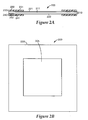
- FIGs 2A and 2B provide a cross sectional view and plan views, respectively, of a single gasketed catalyst coated membrane (CCM) 200 which may be formed as a roll good web in accordance with one embodiment.
- the gasketed CCM 200 includes a CCM 210 having an electrolyte membrane 211 and first and second catalyst layers 221, 222 disposed on the membrane 211.
- First and second gaskets 230, 240 are arranged on surfaces of the CCM 210.
- a gasket 230 form a frame around the active area 205 on one surface of the CCM 210.
- Each gasket 230, 240 includes a gasket layer 231, 241, and an adhesive layer 232, 242, such as a pressure sensitive, thermally or UV activated adhesive layer.
- the gaskets 230, 240 are attached to the CCM via the adhesive layers 232, 242.
- the gasket layer 231, 232 may comprise various types of polymer material, such as polyester, polyimide, polyethylene naphthalate (PEN), polyethylene telephthalate (PET) and/or other similar materials, including rigid polymeric materials that are sufficiently thin, sufficiently strong, and sufficiently compatible with the fuel cell environment, i.e., temperatures of 60-120 °C, in the presence of water, hydrogen and/or oxygen.
- the gasket material has a thickness greater than about 0.0125 mm with an adhesive layer thickness of about 0.00625 to about 0.05 mm.
- the gasket material is a polyester having a thickness of about 0.1 mm.
- the gasket material may include microstructured elastomeric ribs, such as thermally cured ethylene propylene diene monomer (EPDM) elastomeric ribs having a height of about 0.25 mm.
- the first and second gasket layers need not have identical characteristics. The characteristics of the gasket layers may be selected to facilitate component handling or fuel cell operation.
- the first gasket layer 230 may have a different thickness from a second gasket layer 240 and/or the first gasket layer 230 may comprise one or more materials that are different from those of the second gasket layer 240.
- the materials of the gasket layers 231, 241 and the adhesive layers 232, 242 are selected so that the adhesive layers 232, 242 adhere well to the gasket layers 231, 241 and to CCM 210.
- the adhesive layers 232, 242 may comprise a pressure sensitive adhesive (PSA), a heat activated adhesive, a UV activated adhesive, or other type of adhesive.
- the adhesive layer may comprise any of the following: acrylic PSA's, rubber based adhesives, ethylene maleic anhydride copolymers, olefin adhesives such as copolymers of 1-octene with ethylene or propylene, nitrile based adhesives, epoxy based adhesives, and urethane based adhesives.
- the adhesive layer may comprise a thermally activated adhesive, such as Thermobond 845 (polyethylene maleate based) and Thermobond 583 (nitrile rubber based).
- the gasketed CCM 200 illustrated in Figures 2A and 2B may be fabricated as a web comprising a plurality of individual gasketed CCMs in a roll-to-roll process.
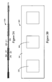
- Figures 3A and 3B illustrate cross sectional and plan views, respectively, of a gasketed CCM web 300 which may be cut to form a plurality of individual gasketed CCMs such as the gasketed CCM illustrated in Figures 2A and 2B .
- Figure 3A illustrates a continuous CCM web comprising a continuous membrane 311 that has continuous catalyst layers 321, 322 disposed thereon.
- the membrane web may be without catalyst or may include patterned catalyst areas rather than continuous catalyst layers.
- the gasketed CCM web 300 of Figure 3A includes gasket layers 331, 341 that frame active areas 305 of a continuous CCM web 300.
- the gasket layers 331, 341 are attached to the CCM web 310 via adhesive layers 332, 342.
- the gasketed CCM web illustrated in Figures 3A and 3B may be fabricated in a roll to roll process.
- fabrication of a gasketed CCM web includes feeding a gasket web, including gasket and adhesive layers, through a cutting station that cuts out a series of active area apertures in the gasket layer, forming a gasket web.
- the cutting station may include, for example, a rotary die cutter, laser cutter or a stationary die.
- the gasket ladder web is transported to a bonding station where it is brought together with a CCM web and another gasket ladder web on the opposite side of the CCM web. Timing of the webs is accomplished by starting the aperture cutters of the cutting stations when a cut is needed and stopping or slowing them between cuts.
- the adhesive layers of the gasket ladder webs may include release liners. If so, the release liners are removed, e.g., peeled away, and the gasket ladder webs are bonded to surfaces of the CCM web at the bonding station via the adhesive layers of the gasket webs.
- Vacuum belt conveyers may be used to hold the gasket ladder webs against the peel force of the liner removal. Peel bars and/or idlers may be used to facilitate speed of the peel.
- the gasket webs may be conveyed to the bonding station on a vacuum belt, or on a convex surface such as a roller, or supported by another web, such as a disposable tape, or deployed on carrier webs, such as releasable adhesive carrier webs.
- the electrolyte membrane employed in fuel cells typically comprises an expensive ionomer. Gasket materials are generally considerably less expensive. When viewed in plan view, the gasket area of a typical gasketed CCM, which is an area situated around the perimeter, covers an appreciable portion of the CCM, preventing the covered area of the CCM from being part of the active area of the fuel cell. While existing electrode designs typically use a membrane that is coextensive with the entire gasketed area, it may be possible to economize on membrane material by removing the membrane from portions covered by the gasket. An electrolyte membrane web or CCM web thrifted in the cross web direction does not extend to the edges of the gasket layers in the cross web direction.
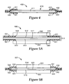
- FIG 4 illustrates a cross sectional view of a gasketed CCM web 400 in the cross web orientation.
- the electrolyte membrane web 411 is thrifted or economized in the cross web direction and does not extend completely to the edges of the gasket layers 431, 441.
- the adhesive layers 432, 442 adhere to the CCM web 411 and to each other to form the seal.
- the CCM web 411 should be intact in the down web direction to maintain the web format.
- the advantages of the thrifting the CCM web 411 in the cross web direction include reduced membrane costs and removal of membrane in the manifold areas which can sometimes be considered a problem due to the humidity changes.
- FIG. 5A illustrates a membrane electrode assembly (MEA) 500 having a gasketed CCM 512 and attached GDLs 550 in accordance with one embodiment.
- the GDLs 550 overlap a portion of the gasket layers 531, 541 of the gasketed CCM 512 providing membrane edge protection when the GDLs 550 are added to produce an MEA 500.
- the GDLs 550 may be attached to the gasketed CCM in a continuous and/or roll-to-roll process.
- FIG. 5B illustrates an MEA 501 incorporating catalyst coated GDLs 551, which are referred to as catalyst coated backings, or CCBs.
- the GDLs 551 include catalyst layers 514, 515 and are disposed within apertures of the gasket layers 531, 541.
- the adhesive layers 532, 542 adhere to the membrane520 and to each other to form the seal.
- the GDLs may be attached to the membrane web via a roll to roll process to form an output MEA web.
- Any suitable electrolyte membrane may be used in the practice of the present invention.
- Useful PEM thicknesses range between about 200 ⁇ m and about 15 ⁇ m.
- NAFION ® is commonly used in making polymer electrolyte membranes for use in fuel cells.
- TFE tetrafluoroethylene
- the catalyst layers may comprise Pt or Pt alloys coated onto larger carbon particles by wet chemical methods, such as reduction of chloroplatinic acid.
- This form of catalyst is dispersed with ionomeric binders and/or solvents to form an ink, paste, or dispersion that is applied either to the membrane, a release liner, or GDL.
- the catalyst layers may comprise nanostructured support elements bearing particles or nanostructured thin films (NSTF) of catalytic material.
- Nanostructured catalyst layers do not contain carbon particles as supports and therefore may be incorporated into very thin surface layers of the electrolyte membrane forming a dense distribution of catalyst particles.
- the use of nanostructured thin film (NSTF) catalyst layers allows much higher catalyst utilization than catalyst layers formed by dispersion methods, and offer more resistance to corrosion at high potentials and temperatures due to the absence of carbon supports.
- the catalyst surface area of a CCM may be further enhanced by using an electrolyte membrane having microstructured features.
- NSTF catalyst layers comprise elongated nanoscopic particles that may be formed by vacuum deposition of catalyst materials on to acicular nanostructured supports.
- Nanostructured supports suitable for use in the present invention may comprise whiskers of organic pigment, such as C.I. PIGMENT RED 149 (perylene red).
- the crystalline whiskers have substantially uniform but not identical cross-sections, and high length-to-width ratios.
- the nanostructured support whiskers are coated with coating materials suitable for catalysis, and which endow the whiskers with a fine nanoscopic surface structure capable of acting as multiple catalytic sites.
- the nanostructured support elements may be extended through continued screw dislocation growth. Lengthening the nanostructured support elements allows for an increased surface area for catalysis. Processes for lengthening the nanostructured support elements are described in previously incorporated U.S. Patent Application S/N 11/225,690 . Additionally, or alternatively, multiple layers of nanostructured support elements also provide for an increased surface area. Processes producing multiple layers of nanostructured support elements are described in previously incorporated U.S. Patent Application S/N 11/224,879 .
- the nanostructured support elements are coated with a catalyst material to form a nanostructured thin film catalyst layer.
- the catalyst material comprises a metal, such as a platinum group metal.
- the catalyst coated nanostructured support elements may be transferred to a surface of an electrolyte membrane to form a catalyst coated membrane.
- the catalyst coated nanostructured support elements maybe formed on a GDL surface.
- the GDLs can be any material capable of collecting electrical current from the electrode while allowing reactant gasses to pass through, typically a woven or non-woven carbon fiber paper or cloth.
- the GDLs provide porous access of gaseous reactants and water vapor to the catalyst and membrane, and also collect the electronic current generated in the catalyst layer for powering the external load.
- the GDLs may include a microporous layer (MPL) and an electrode backing layer (EBL), where the MPL is disposed between the catalyst layer and the EBL.
- EBLs may be any suitable electrically conductive porous substrate, such as carbon fiber constructions (e.g., woven and non-woven carbon fiber constructions).
- EBLs may also be treated to increase or impart hydrophobic properties.
- EBLs may be treated with highly-fluorinated polymers, such as polytetrafluoroethylene (PTFE) and fluorinated ethylene propylene (FEP).
- PTFE polytetrafluoroethylene
- FEP fluorinated ethylene propylene
- the carbon fiber constructions of EBLs generally have coarse and porous surfaces, which exhibit low bonding adhesion with catalyst layers.
- the microporous layer may be coated to the surface of EBLs. This smoothens the coarse and porous surfaces of EBLs, which provides enhanced bonding adhesion with some types of catalyst layers.
- Embodiments of the invention are directed to processes for fabricating roll good half or full gasketed electrolyte membrane webs, CCM webs, and/or MEA webs.
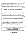
- Figure 6A is a diagram illustrating a method that may be used to fabricate a half gasketed membrane web in accordance with embodiments of the invention. The process involves cutting 615 spaced apart apertures in a gasket web and transporting 625 the resulting gasket web to a bonding station.
- the gasket web includes a gasket layer and an adhesive layer that may optionally include a release liner.
- the gasket web may be delivered from an unwind wheel or another source. After the cutting the apertures, the resulting gasket web resembles a ladder-like structure that may be supported and transported through portions of the fabrication process on a vacuum conveyor or other support mechanism.
- a membrane web which may be a CCM web having continuous or patterned catalyst layers is transported 635 to the bonding station.
- the gasket web and a membrane web are brought together. Registration between the gasket web and the membrane web may be implemented if the membrane web includes patterned catalyst areas.
- the gasket web and the membrane web are bonded 645 at the bonding station, through one or more of heat, pressure, and UV exposure for example.
- Figure 6B is a flow diagram illustrating a method that may be used to fabricate gasketed membrane and/or MEA webs in accordance with embodiments of the invention.
- the method involves movement of various material webs through the fabrication process.
- the process involves cutting 610 spaced apart apertures in a first gasket web and transporting 620 the resulting first gasket web to a bonding station. Apertures are cut 630 in a second gasket web and the resulting second gasket web is transported 640 to the bonding station.
- Each of the first and second gasket webs include a gasket layer and an adhesive layer that may optionally include a release liner.
- the first and second gasket webs may be delivered from unwind wheels or another source. After the cutting the apertures, the resulting gasket webs resemble ladder-like structures that may be supported and transported through portions of the fabrication process on a vacuum conveyor or other support mechanism.
- the first gasket web, the second gasket web and a membrane web are brought together.
- the first and second gasket webs and the membrane web are aligned. Registration between the first gasket web and the second gasket web may be controlled so that the apertures of the first and second gasket webs are aligned with each other on first and second surfaces of the membrane web.
- first gasket web and the second gasket web are respectively attached 650 to first and second surfaces of the membrane web via the adhesive layers of the gasket webs.
- attachment of the first and second gasket ladder webs occurs substantially simultaneously by running all three webs through a single pair of bonding rollers.
- the first and second gasket webs are attached to the membrane web sequentially.
- the membrane web comprises a CCM web with catalyst disposed over the surface of the membrane web or patterned in regions on the membrane web. If a patterned CCM web is used, the patterned regions are aligned with the apertures of the first and second gasket webs.
- the resulting gasketed membrane web or CCM web may be rolled up and stored for later use, or may be immediately used in subsequent fabrication processes to make an MEA web and/or other fuel cell subassemblies.
- an MEA web maybe formed using the gasketed membrane web by attaching 660 GDLs or CCBs at the membrane web areas exposed by apertures in the gasket layers.
- the GDLs or CCBs may be disposed within the apertures of the gasket layers on both surfaces of the membrane web.
- the GDLs or CCBs may overlap the gasket layers at the inner edges of the gasket layers.
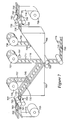
- FIG. 7 An apparatus that processes input webs of fuel cell materials and produces roll good gasketed CCMs is illustrated in Figure 7 .
- the apparatus of Figure 7 can produce roll good gasketed membrane webs using roll good gasket webs and roll good electrolyte membrane webs or CCM webs.
- the apparatus of Figure 7 provides a unique approach to fabricating a gasketed membrane web that may be separated into multiple individual gasketed membranes or gasketed CCMs or may be used in a subsequent roll to roll process to fabricate fuel cell components.
- fabrication of a gasketed membrane web includes feeding an uncut first gasket web 715, including a gasket layer, an adhesive layer, and an adhesive release liner from a first unwind wheel 705 and through a first cutting station 725.
- the cutting station 725 cuts out a series of active area apertures 701 in the gasket web 715, forming a ladder-like first gasket web 735.
- the release liner 757 of the first gasket web 735 is removed. Removal of the release liner 757 is facilitated by a peel bar 745 or idler and the release liner 757 is rolled up on a first waste wheel 755.
- An uncut second gasket web 716 is delivered from a second unwind wheel 706 and fed through a second cutting station 726.
- the second cutting station 726 cuts out a series of active area apertures 702 in the second gasket web 716, forming a ladder-like second gasket web 736.
- the release liner 758 of the second gasket web 736 is removed. Removal of the release liner 758 is facilitated by a peel bar 746 or idler and the release liner 758 is rolled up on a second waste wheel 756.
- the cutting stations 725, 726 may include, for example, rotary die cutters or laser cutters.
- the cutting stations 725, 726 include vacuum die cutters 727, 728. Vacuum is turned on at the vacuum die cutters 727, 728 to remove the cut aperture slugs 783, 793 from the gasket web 735, 736. The vacuum is removed as the leading edges of the aperture slugs 783, 793 are rotated about 225° from the cutting surface. Removing the vacuum releases the aperture slugs 783, 793 to trays 782, 792 or to a vacuum scrap disposal plenum.
- Spring accumulators 780, 790 may be used to hold the slugs 783, 793 so that upon release of the vacuum the slugs 783, 793 are pushed into the trays 782, 792 or plenum with friction from the dies 727, 728.
- the first and second gasket webs 735, 736 are transported to a bonding station, which, in this example, comprises cylindrical bonding rollers 760.
- a bonding station which, in this example, comprises cylindrical bonding rollers 760.
- the gasket webs 735, 736 are transported to the bonding rollers 760 on vacuum conveyers 765, 766.
- a membrane web 717 is delivered from a membrane unwind wheel 707 and is transported to the bonding rollers 760.
- Sensors 781, 791 are used to detect the leading edge of the aperture cut. Bias and registration marks sensed by sensor 781, 791, e.g., a retro reflective laser sensor, are used to align the left hand gasket ladder 735 with the right hand gasket ladder 736. If the membrane web 717 includes patterned catalyst areas 718, a sensor 797, such as a through beam fiber optic sensor, may be used to detect the leading edge of the catalyst areas. Output from the sensor 797 is used by a control system along with information from sensor 781 or 791 to align the catalyst areas 718 to the gasket webs 735 and 736. Fiducial marks 799 may be sensed by sensor 778 to facilitate alignment of the three webs 735, 736, 717.
- Information from sensors may be used by a control system to control the speed and longitudinal position of one or more of the first gasket web 735, the second gasket web 736 and the membrane web 717. Timing of the webs 735, 736, 717 to facilitate alignment may be accomplished by starting the aperture cutters 727, 728 of the cutting stations 725, 726 when a cut is needed and stopping or slowing them between cuts. Matching the speed of the cutting stations 725, 726 and bonding rollers 760 during the aperture cutting keeps aperture size constant in gasket webs 735, 736.
- gasket webs 735, 736 are brought together with the membrane web 717 at the bonding rollers 760.
- the gasket webs 735, 736 are bonded substantially simultaneously to respective first and second surfaces of the membrane web 717 by the bonding rollers 760 via the adhesive layers of the gasket webs 735, 736 to form a gasketed membrane web 770.
- the adhesive layers of the gasket webs 735, 736 comprise pressure sensitive adhesive. In these embodiments attachment of the gasket webs 735, 736 may be effected by application of pressure via the bonding rollers 760 operating at room temperature. In other embodiments, the adhesive layers of the gasket webs 735, 736 comprise a thermally activated adhesive and the bonding rollers 760 are heated to facilitate attachment of the gasket webs 735, 736 to the membrane web 717. In yet other embodiments, the adhesive comprises a UV activated adhesive. If an UV activated adhesive is used, bonding is facilitated by exposure to UV light via a light source which may be located near the bonding rollers 760. Adhesive release liners may or may not be used.
- the gasketed membrane web 770 is wound on a wind wheel for storage and/or later use in subsequent processing. In other implementations, the gasketed membrane web 770 is transported to another processing stage, such as a processing stage for formation of an MEA web incorporating the gasketed membrane web 770.
- Figure 8 illustrates a fabrication apparatus wherein a first gasket web 835 and optionally a second gasket web 836 are bonded to a membrane web.
- a half gasketed membrane may be formed by bonding the first gasket web 845 to the membrane 817.
- the second gasket web 836 is not bonded to the membrane 817.
- the half gasketed membrane may be used in applications where a thinner web is required.
- a second gasket web 836 may be attached to the membrane 817 to form a full gasketed membrane web as described below. If a full gasketed membrane web is formed, the first and second gasket webs 835, 836 may be sequentially bonded to the membrane web 817. For example, as illustrated in Figure 8 , the second gasket web 836 is attached to the membrane web 817 after attachment of the first gasket web 835.
- Fabrication of a gasketed membrane web 871 includes feeding an uncut first gasket web 815, including a gasket layer, an adhesive layer, and an adhesive release liner from a first unwind wheel 805 and through a first cutting station 825.
- the cutting station 825 may include a vacuum die cutter 827 that picks up and deposits the aperture slugs 883 in a tray 882 using a spring accumulator 880.
- the cutting station 825 cuts out a series of active area apertures 801 in the gasket web 815, forming a ladder-like first gasket web 835.
- the release liner 857 of the first gasket web 835 is removed. Removal of the release liner 857 is facilitated by a peel bar 845 or idler and the release liner 857 is rolled up on a first waste wheel 855.
- the first gasket web 835 is transported on a vacuum conveyer or other transport mechanism 865 to a bonding station, which, in this example, comprises cylindrical bonding rollers 860.
- a membrane web 817 is delivered from a membrane unwind wheel 807 and is transported to the bonding rollers 860.
- information acquired from one or more sensors may be used by a control system to align the first gasket web 835 for placement on the membrane web 817 in proper alignment with the catalyst areas 818.
- the first gasket web 835 is brought together with the membrane web 817 at the bonding rollers 860.
- the gasket web 835 is bonded to a first surface of the membrane web 817 by the bonding rollers 860 via the exposed adhesive layer of the first gasket web 835 to form a partially gasketed membrane web 870.
- An uncut second gasket web 816 is delivered from a second unwind wheel 806 and fed through a second cutting station 826.
- the second cutting station 826 uses a vacuum die cutter 828 to cut out a series of active area apertures 802 in the second gasket web 816, forming a ladder-like second gasket web 836.
- Aperture slugs 893 are picked up by the vacuum die cutter 828 through use of a spring accumulator 890 and are deposited in tray 892.
- the release liner 858 of the second gasket web 836 is removed. Removal of the release liner 858 is facilitated by a peel bar 846 or idler and the release liner 858 is rolled up on a second waste wheel 856.
- the cutting stations 825, 826 may include, for example, rotary die cutters or laser cutters.
- Removal of the release liner 858 of the second gasket web 836 exposes the adhesive layers of the second gasket web 836.
- the second gasket web 836 is transported on a vacuum conveyer or other transport mechanism 866 to a bonding station, which, in this example, comprises cylindrical bonding rollers 861.
- the partially gasketed membrane web 870 is delivered to the bonding rollers 861.
- one or more sensors may be used to align the second gasket web 836 for placement on the membrane web 870.
- the second gasket web 836 may be aligned with respect to the first gasket web 835 disposed on the partially gasketed membrane web 870.
- fiducial marks 899 sensed by sensor 898 may be used to facilitate alignment of the three webs 835, 836, 817.
- the fully gasketed membrane web 871 is wound on a wind wheel for storage and/or later use in subsequent processing.
- the gasketed membrane web 871 is transported to another processing stage, such as a processing stage for formation of an MEA web incorporating the gasketed membrane web 871 as illustrated in Figure 9 .
- Figure 9 illustrates an apparatus configured to fabricate a roll good MEA web having a gasketed membrane web.
- a gasketed membrane web such as a gasketed CCM web 950 is delivered from an unwind wheel 903 or directly from a previous process.
- First GDLs 921 disposed on a carrier web 920 are delivered from a unwind wheel 901 or from a previous process.
- the first GDLs 921 and the CCM web 950 are transported to bonding rollers 922 where the first GDLs 921 are aligned with respect to apertures 951 in the gasket layer of the CCM web 950.
- the first GDLs 921 are bonded to a first surface of the gasketed membrane web 950.
- the first GDLs 921 may be aligned for placement within the apertures 951 of the gasketed CCM web 950 or may be aligned so that the first GDLs 921 slightly overlap the gasket.
- Second GDLs 931 disposed on carrier web 930 are delivered from an unwind wheel 902 or from a previous process.
- Second GDLs 931 disposed on a carrier web 930 are delivered from a unwind wheel 902 or from a previous process.
- the second GDLs 931 and the CCM web 952 are transported to bonding rollers 932 where the second GDLs 931 are aligned with respect to apertures 951 in the gasket layer of the CCM web 952.
- the second GDLs 931 are bonded to a second surface of the gasketed membrane web 952 to form a roll good MEA web 953.
- GDLs may be attached to web using heat and pressure or using an adhesive layer deposited on at least a portion of the GDL or the CCM or gasket if the GDLs overlap the gasket, wherein the adhesive layer may comprise an adhesive available from 3M Company under the Fastbond series or an ionomer.
- the first and second GDLs may fit within the apertures 951 of the gasketed CCM web 950 on one or more edges and overlap the gasket on one or more edges.
Landscapes
- Life Sciences & Earth Sciences (AREA)
- Engineering & Computer Science (AREA)
- Manufacturing & Machinery (AREA)
- Sustainable Development (AREA)
- Sustainable Energy (AREA)
- Chemical & Material Sciences (AREA)
- Chemical Kinetics & Catalysis (AREA)
- Electrochemistry (AREA)
- General Chemical & Material Sciences (AREA)
- Fuel Cell (AREA)
- Inert Electrodes (AREA)
Applications Claiming Priority (2)
| Application Number | Priority Date | Filing Date | Title |
|---|---|---|---|
| US11/611,575 US8288059B2 (en) | 2006-12-15 | 2006-12-15 | Processing methods and systems for assembling fuel cell perimeter gaskets |
| PCT/US2007/086218 WO2008108898A2 (en) | 2006-12-15 | 2007-12-03 | Processing methods and systems for assembling fuel cell perimeter gaskets |
Publications (2)
| Publication Number | Publication Date |
|---|---|
| EP2097943A2 EP2097943A2 (en) | 2009-09-09 |
| EP2097943B1 true EP2097943B1 (en) | 2013-04-17 |
Family
ID=39527704
Family Applications (1)
| Application Number | Title | Priority Date | Filing Date |
|---|---|---|---|
| EP07873880.4A Not-in-force EP2097943B1 (en) | 2006-12-15 | 2007-12-03 | Processing method for assembling fuel cell perimeter gaskets |
Country Status (5)
| Country | Link |
|---|---|
| US (2) | US8288059B2 (enExample) |
| EP (1) | EP2097943B1 (enExample) |
| JP (1) | JP5324465B2 (enExample) |
| CN (1) | CN101558522B (enExample) |
| WO (1) | WO2008108898A2 (enExample) |
Cited By (3)
| Publication number | Priority date | Publication date | Assignee | Title |
|---|---|---|---|---|
| DE102015214361A1 (de) * | 2015-07-29 | 2017-02-02 | Bayerische Motoren Werke Ag | Verfahren und Vorrichtung zur Herstellung von Membran-Elektroden-Einheiten für Brennstoffzellen |
| DE102020130578A1 (de) | 2020-11-19 | 2022-05-19 | Lacom Gmbh | Verfahren zur Herstellung einer Membran-Elektroden-Anordnung sowie eine Membran-Elektroden-Anordnung für eine Brennstoffzelle |
| DE102022214154A1 (de) | 2022-12-21 | 2024-06-27 | Robert Bosch Gesellschaft mit beschränkter Haftung | Verfahren zur Herstellung von Membranelektrodenanordnungen für eine elektrochemische Zelleneinheit |
Families Citing this family (60)
| Publication number | Priority date | Publication date | Assignee | Title |
|---|---|---|---|---|
| WO2009048991A1 (en) * | 2007-10-08 | 2009-04-16 | Ames Rubber Corporation | Composite multilayer seal for pem fuel cell applications and method for constructing the same |
| US7935453B2 (en) * | 2008-01-10 | 2011-05-03 | GM Global Technology Operations LLC | Membrane with optimized dimensions for a fuel cell |
| JP2009193860A (ja) * | 2008-02-15 | 2009-08-27 | Asahi Glass Co Ltd | 固体高分子形燃料電池用膜電極接合体およびその製造方法 |
| KR100957368B1 (ko) * | 2008-04-11 | 2010-05-12 | 현대자동차주식회사 | 연료전지용 mea 소재 자동 타발 및 접합 설비 |
| KR20100004495A (ko) * | 2008-07-04 | 2010-01-13 | 현대자동차주식회사 | 연료전지 스택의 막-전극 접합체와 가스확산층간의 접합방법 |
| JP5348388B2 (ja) * | 2008-11-12 | 2013-11-20 | トヨタ自動車株式会社 | 燃料電池の製造方法 |
| US8507152B2 (en) * | 2009-05-14 | 2013-08-13 | GM Global Technology Operations LLC | Fabrication of electrodes with multiple nanostructured thin catalytic layers |
| US8481231B2 (en) * | 2009-05-14 | 2013-07-09 | GM Global Technology Operations LLC | Preparation of nanostructured thin catalytic layer-based electrode ink |
| US8802329B2 (en) | 2009-05-14 | 2014-08-12 | GM Global Technology Operations LLC | Electrode containing nanostructured thin catalytic layers and method of making |
| US8512908B2 (en) | 2009-05-14 | 2013-08-20 | GM Global Technology Operations LLC | Fabrication of catalyst coated diffusion media layers containing nanostructured thin catalytic layers |
| KR101470036B1 (ko) * | 2009-12-01 | 2014-12-05 | 현대자동차주식회사 | 연료 전지의 막전극접합체와 기체 확산층 구조 및 이의 접합 방법 |
| WO2011146094A1 (en) * | 2009-12-22 | 2011-11-24 | 3M Innovative Properties Company | Fuel cell subassemblies incorporating subgasketed thrifted membranes |
| US20110171562A1 (en) * | 2010-01-08 | 2011-07-14 | Gm Global Technology Operations, Inc. | Process for forming a membrane-subgasket assembly using vacuum sealing |
| GB2478154B (en) * | 2010-02-26 | 2016-02-24 | Intelligent Energy Ltd | Laminated fuel cell assembly |
| US20110287338A1 (en) * | 2010-05-21 | 2011-11-24 | Gm Global Technology Operations, Inc. | Low level cerium mitigation with electrode edge protection |
| US8445164B2 (en) | 2010-05-27 | 2013-05-21 | GM Global Technology Operations LLC | Electrode containing nanostructured thin catalytic layers and method of making |
| JP5633348B2 (ja) | 2010-12-06 | 2014-12-03 | 新東工業株式会社 | 積層接合体製造装置及び積層接合体の製造方法 |
| KR101243704B1 (ko) | 2010-12-07 | 2013-03-13 | 현대자동차주식회사 | 연료전지 스택 제작 방법 |
| PL2669079T3 (pl) | 2011-01-27 | 2016-08-31 | Sintokogio Ltd | Laminowane urządzenie unieruchamiające, system do wytwarzania laminowanego zestawu i sposób wytwarzania laminowanego zestawu |
| CN102529303A (zh) * | 2011-12-31 | 2012-07-04 | 武汉理工大学 | 薄膜双面自动对位间歇式涂敷方法 |
| KR101423614B1 (ko) * | 2012-01-12 | 2014-07-25 | 지에스칼텍스 주식회사 | 연료전지용 막전극접합체 |
| US8518596B1 (en) | 2012-05-16 | 2013-08-27 | GM Global Technology Operations LLC | Low cost fuel cell diffusion layer configured for optimized anode water management |
| GB2502517A (en) * | 2012-05-28 | 2013-12-04 | Intelligent Energy Ltd | Fuel Cell Plate Assemblies and methods of assembly thereof |
| DE102012020975A1 (de) * | 2012-10-25 | 2014-04-30 | Volkswagen Aktiengesellschaft | Membran-Elektroden-Anordnung, Brennstoffzelle mit einer solchen und Kraftfahrzeug mit der Brennstoffzelle |
| JP5829203B2 (ja) * | 2012-12-03 | 2015-12-09 | 本田技研工業株式会社 | 燃料電池 |
| WO2014111745A2 (en) * | 2013-01-18 | 2014-07-24 | Daimler Ag | Fuel cell assemblies and preparation methods therefor |
| WO2015095021A1 (en) * | 2013-12-17 | 2015-06-25 | 3M Innovative Properties Company | Membrane electrode assembly and methods of making the same |
| CN105849934A (zh) | 2013-12-17 | 2016-08-10 | 3M创新有限公司 | 膜电极组件及其制备方法 |
| KR101575312B1 (ko) * | 2014-10-21 | 2015-12-07 | 현대자동차 주식회사 | 연료전지의 막-전극 어셈블리 제조 장치 |
| KR101684550B1 (ko) * | 2015-07-29 | 2016-12-08 | 현대자동차 주식회사 | 연료전지용 막-전극 어셈블리의 제조장치 및 방법 |
| DE102015010422A1 (de) * | 2015-08-11 | 2017-02-16 | Daimler Ag | Verfahren zum Herstellen einer Membran-Elektroden-Anordnung für eine Brennstoffzelle |
| DE102016000974B4 (de) * | 2016-01-29 | 2017-10-19 | Daimler Ag | Verfahren und Vorrichtung zum Herstellen einer Membran-Elektroden-Anordnung für eine Brennstoffzelle |
| KR20170103566A (ko) * | 2016-03-04 | 2017-09-13 | 현대자동차주식회사 | 연료전지 부품 및 이의 제조장치 |
| JP6212155B2 (ja) * | 2016-03-18 | 2017-10-11 | 本田技研工業株式会社 | 燃料電池用膜電極接合体の製造方法 |
| US10198076B2 (en) | 2016-09-06 | 2019-02-05 | Neosensory, Inc. | Method and system for providing adjunct sensory information to a user |
| KR102487171B1 (ko) * | 2016-12-14 | 2023-01-10 | 기아 주식회사 | Mea 제조시 가스켓 커팅시점의 설정방법, 및 설정시스템 |
| JP6817850B2 (ja) * | 2017-02-27 | 2021-01-20 | 株式会社Screenホールディングス | ガスケット付加装置およびガスケット付加方法 |
| DE102018102642B4 (de) * | 2018-02-06 | 2021-09-23 | Kuka Systems Gmbh | Fügevorrichtung, Fügeverfahren und Herstellungsverfahren für einen Lagenverbund einer Energieumwandlungsvorrichtung |
| US20190273268A1 (en) * | 2018-03-02 | 2019-09-05 | Honda Motor Co., Ltd. | Frame equipped membrane electrode assembly, method of producing the frame equipped membrane electrode assembly, and fuel cell |
| JP7052483B2 (ja) * | 2018-03-29 | 2022-04-12 | トヨタ自動車株式会社 | 一体化シートの製造方法 |
| KR102064835B1 (ko) | 2018-10-24 | 2020-01-10 | (주) 고송이엔지 | 수소연료전지용 셀의 자동 레이아웃 장치에 적용되는 히팅 블럭 및 상기 히팅 블럭을 포함하는 수소연료전지용 셀의 자동 레이아웃 장치 |
| CN110311151B (zh) * | 2019-07-05 | 2020-11-20 | 深圳市南科燃料电池有限公司 | 带密封的催化剂涂覆膜的制备方法 |
| KR102869206B1 (ko) * | 2019-10-30 | 2025-10-10 | 현대자동차주식회사 | 전해질막의 소비량을 저감할 수 있는 막-전극 접합체의 제조방법 |
| KR102817480B1 (ko) * | 2019-12-31 | 2025-06-05 | 현대자동차주식회사 | 막-전극 접합체의 제조방법 |
| CN113381045A (zh) * | 2020-02-25 | 2021-09-10 | 山东魔方新能源科技有限公司 | 一种燃料电池膜电极及其制备方法 |
| CN111572053B (zh) * | 2020-05-29 | 2021-12-14 | 常州达姆斯检测技术有限公司 | 一种复合材料测试样条的加工方法 |
| CN112582654B (zh) * | 2020-12-08 | 2021-12-14 | 无锡先导智能装备股份有限公司 | 膜电极的制造方法 |
| CN112582655B (zh) * | 2020-12-08 | 2021-10-22 | 无锡先导智能装备股份有限公司 | 膜电极的制造设备 |
| KR20230154173A (ko) * | 2021-03-03 | 2023-11-07 | 도판 인사츠 가부시키가이샤 | 막 전극 접합체의 집합 롤, 막 전극 접합체, 및 고체고분자형 연료 전지 |
| KR20220125769A (ko) * | 2021-03-05 | 2022-09-14 | 현대모비스 주식회사 | 막-전극 가스켓 어셈블리 제조 장치 |
| KR102655524B1 (ko) * | 2021-05-18 | 2024-04-09 | 주식회사 나인테크 | 연료전지 제조방법 |
| CN115799527A (zh) * | 2021-09-09 | 2023-03-14 | 江苏清能新能源技术股份有限公司 | 燃料电池的膜电极的制作方法以及装置 |
| DE102021123475A1 (de) * | 2021-09-10 | 2023-03-30 | Greenerity Gmbh | Verfahren zur Herstellung von Membranelektrodenanordnungen in Form einer kontinuierlichen Bahn |
| DE102021212252A1 (de) * | 2021-10-29 | 2023-05-04 | OPTIMA life science GmbH | Verfahren und Vorrichtung zur Herstellung von Membran-Baugruppen |
| KR102900703B1 (ko) * | 2021-12-28 | 2025-12-15 | 코오롱인더스트리 주식회사 | 막-전극 접합체 및 이를 포함하는 연료전지 |
| DE102022207518B4 (de) * | 2022-07-22 | 2024-07-18 | OPTIMA life science GmbH | Verfahren und Vorrichtung zur positionsgenauen Bearbeitung einer Materialbahn |
| DE102022118477B3 (de) | 2022-07-25 | 2023-09-28 | Audi Aktiengesellschaft | Verfahren zur Herstellung einer mit einer Dichtung versehenen Membran-Elektrodenanordnung |
| DE102024109965A1 (de) * | 2024-04-10 | 2025-10-16 | Cellcentric Gmbh & Co. Kg | Verfahren und Vorrichtung zum Herstellen eines Verbundes für eine elektrochemische Zelle |
| KR20260005499A (ko) * | 2024-07-03 | 2026-01-12 | 삼성에스디아이 주식회사 | 전고체 전지 제조 장치 및 이를 이용한 전고체 전지 제조 방법 |
| CN119230869B (zh) * | 2024-12-04 | 2025-03-18 | 嘉兴大学 | 用于氢燃料电池的组合设备 |
Family Cites Families (39)
| Publication number | Priority date | Publication date | Assignee | Title |
|---|---|---|---|---|
| US4812352A (en) | 1986-08-25 | 1989-03-14 | Minnesota Mining And Manufacturing Company | Article having surface layer of uniformly oriented, crystalline, organic microstructures |
| JPH04141914A (ja) * | 1990-10-02 | 1992-05-15 | Showa Electric Wire & Cable Co Ltd | シールド付テープ状電線の製造方法 |
| AU4186096A (en) | 1994-12-17 | 1996-07-03 | Loughborough University Innovations Limited | Electrolytic and fuel cell arrangements |
| JPH1145729A (ja) * | 1997-07-25 | 1999-02-16 | Fuji Electric Co Ltd | 固体高分子電解質型燃料電池 |
| US6136412A (en) | 1997-10-10 | 2000-10-24 | 3M Innovative Properties Company | Microtextured catalyst transfer substrate |
| US5879827A (en) | 1997-10-10 | 1999-03-09 | Minnesota Mining And Manufacturing Company | Catalyst for membrane electrode assembly and method of making |
| US6291091B1 (en) * | 1997-12-24 | 2001-09-18 | Ballard Power Systems Inc. | Continuous method for manufacturing a Laminated electrolyte and electrode assembly |
| WO2000010216A1 (en) * | 1998-08-10 | 2000-02-24 | Gore Enterprise Holdings, Inc. | A membrane electrode gasket assembly |
| US6454978B1 (en) * | 2000-06-16 | 2002-09-24 | Avery Dennison Corporation | Process for making fuel cell plates |
| CA2412869C (en) | 2000-06-29 | 2010-10-05 | Nok Corporation | Constituent part for fuel cell |
| JP4224668B2 (ja) | 2001-06-15 | 2009-02-18 | Nok株式会社 | 燃料電池用構成部品 |
| JP4412448B2 (ja) | 2001-06-20 | 2010-02-10 | Nok株式会社 | 燃料電池用構成部品 |
| JP5208338B2 (ja) * | 2001-06-29 | 2013-06-12 | 本田技研工業株式会社 | 電解質膜・電極構造体及び燃料電池セル |
| US6869717B2 (en) | 2001-07-09 | 2005-03-22 | Hydrogenics Corporation | Manifold for a fuel cell system |
| US20030082430A1 (en) | 2001-10-25 | 2003-05-01 | Daisuke Suzuki | Fuel cell gasket assembly and method of making |
| US20030221311A1 (en) | 2002-03-20 | 2003-12-04 | Smith Jeffrey A. | Fuel cell assembly and sealing |
| US7432009B2 (en) * | 2002-04-03 | 2008-10-07 | 3M Innovative Properties Company | Lamination apparatus and methods |
| US20040042789A1 (en) * | 2002-08-30 | 2004-03-04 | Celanese Ventures Gmbh | Method and apparatus for transferring thin films from a source position to a target position |
| TW581327U (en) | 2002-12-04 | 2004-03-21 | Asia Pacific Fuel Cell Tech | Integrated dual electrode plate module of fuel cell set |
| US7049024B2 (en) * | 2003-04-30 | 2006-05-23 | Hewlett-Packard Development Company, L.P. | Membrane electrode assemblies and method for manufacture |
| US7195690B2 (en) * | 2003-05-28 | 2007-03-27 | 3M Innovative Properties Company | Roll-good fuel cell fabrication processes, equipment, and articles produced from same |
| JP4141914B2 (ja) | 2003-07-18 | 2008-08-27 | 株式会社フジクラ | グレーテッドインデックス型マルチモードファイバおよびその製造方法 |
| US20050095490A1 (en) | 2003-10-31 | 2005-05-05 | Mittelstadt Laurie S. | Fuel cell assembly gasket for fuel containment |
| US7214442B2 (en) | 2003-12-02 | 2007-05-08 | Los Alamos National Security, Llc | High specific power, direct methanol fuel cell stack |
| KR101147238B1 (ko) | 2004-06-29 | 2012-05-18 | 삼성에스디아이 주식회사 | 연료 전지 시스템 및 그 스택 |
| US20060029850A1 (en) * | 2004-08-03 | 2006-02-09 | Peter Szrama | Fuel cell assembly with structural film |
| EP1624512A2 (en) | 2004-08-05 | 2006-02-08 | Pemeas GmbH | Long-life membrane electrode assemblies |
| US7237406B2 (en) | 2004-09-07 | 2007-07-03 | Modine Manufacturing Company | Condenser/separator and method |
| US7291415B2 (en) | 2004-11-23 | 2007-11-06 | Versa Power Systems, Ltd. | Solid oxide fuel cell with external manifolds |
| US20060127738A1 (en) | 2004-12-13 | 2006-06-15 | Bhaskar Sompalli | Design, method and process for unitized mea |
| US7862956B2 (en) | 2004-12-29 | 2011-01-04 | 3M Innovative Properties Company | Z-axis electrically conducting flow field separator |
| KR100657416B1 (ko) | 2005-01-12 | 2006-12-14 | 주식회사 엘지화학 | 가스켓 일체형 전극막 접합체 및 이를 구비한 연료전지 |
| US20060263558A1 (en) | 2005-05-23 | 2006-11-23 | Ward/Kraft | Continuous intermediate prime label pressure sensitive assembly |
| JP4852894B2 (ja) * | 2005-05-31 | 2012-01-11 | 日産自動車株式会社 | 電解質膜−電極接合体の製造方法 |
| JP5157050B2 (ja) | 2005-08-02 | 2013-03-06 | 日産自動車株式会社 | 膜電極接合体及びその製造方法 |
| US20080020923A1 (en) | 2005-09-13 | 2008-01-24 | Debe Mark K | Multilayered nanostructured films |
| US20070059452A1 (en) | 2005-09-13 | 2007-03-15 | Debe Mark K | Formation of nanostructured layers through continued screw dislocation growth |
| US20080118802A1 (en) | 2006-11-16 | 2008-05-22 | Peter Szrama | Fully Catalyzed Membrane Assembly With Attached Border |
| US7732083B2 (en) * | 2006-12-15 | 2010-06-08 | 3M Innovative Properties Company | Gas diffusion layer incorporating a gasket |
-
2006
- 2006-12-15 US US11/611,575 patent/US8288059B2/en not_active Expired - Fee Related
-
2007
- 2007-12-03 WO PCT/US2007/086218 patent/WO2008108898A2/en not_active Ceased
- 2007-12-03 EP EP07873880.4A patent/EP2097943B1/en not_active Not-in-force
- 2007-12-03 CN CN200780046285.0A patent/CN101558522B/zh not_active Expired - Fee Related
- 2007-12-03 JP JP2009541473A patent/JP5324465B2/ja not_active Expired - Fee Related
-
2012
- 2012-09-12 US US13/611,103 patent/US8609296B2/en not_active Expired - Fee Related
Cited By (4)
| Publication number | Priority date | Publication date | Assignee | Title |
|---|---|---|---|---|
| DE102015214361A1 (de) * | 2015-07-29 | 2017-02-02 | Bayerische Motoren Werke Ag | Verfahren und Vorrichtung zur Herstellung von Membran-Elektroden-Einheiten für Brennstoffzellen |
| DE102020130578A1 (de) | 2020-11-19 | 2022-05-19 | Lacom Gmbh | Verfahren zur Herstellung einer Membran-Elektroden-Anordnung sowie eine Membran-Elektroden-Anordnung für eine Brennstoffzelle |
| DE102022214154A1 (de) | 2022-12-21 | 2024-06-27 | Robert Bosch Gesellschaft mit beschränkter Haftung | Verfahren zur Herstellung von Membranelektrodenanordnungen für eine elektrochemische Zelleneinheit |
| WO2024133041A1 (de) | 2022-12-21 | 2024-06-27 | Robert Bosch Gmbh | Verfahren zur herstellung von membranelektrodenanordnungen für eine elektrochemische zelleneinheit |
Also Published As
| Publication number | Publication date |
|---|---|
| CN101558522A (zh) | 2009-10-14 |
| CN101558522B (zh) | 2014-09-24 |
| US8288059B2 (en) | 2012-10-16 |
| EP2097943A2 (en) | 2009-09-09 |
| JP5324465B2 (ja) | 2013-10-23 |
| WO2008108898A2 (en) | 2008-09-12 |
| US8609296B2 (en) | 2013-12-17 |
| US20080145712A1 (en) | 2008-06-19 |
| WO2008108898A3 (en) | 2008-12-04 |
| JP2010514102A (ja) | 2010-04-30 |
| US20130004882A1 (en) | 2013-01-03 |
Similar Documents
| Publication | Publication Date | Title |
|---|---|---|
| EP2097943B1 (en) | Processing method for assembling fuel cell perimeter gaskets | |
| EP2102930B1 (en) | Method and apparatus for fabricating roll good fuel cell subassemblies | |
| US10446868B2 (en) | Fuel cell subassemblies incorporating subgasketed thrifted membranes | |
| EP2095453B1 (en) | Gas diffusion layer incorporating a gasket | |
| EP1629559B1 (en) | Roll-good fuel cell fabrication processes, equipment, and articles produced from same | |
| JP2024520997A (ja) | 触媒被覆膜及び製造方法 |
Legal Events
| Date | Code | Title | Description |
|---|---|---|---|
| PUAI | Public reference made under article 153(3) epc to a published international application that has entered the european phase |
Free format text: ORIGINAL CODE: 0009012 |
|
| 17P | Request for examination filed |
Effective date: 20090630 |
|
| AK | Designated contracting states |
Kind code of ref document: A2 Designated state(s): AT BE BG CH CY CZ DE DK EE ES FI FR GB GR HU IE IS IT LI LT LU LV MC MT NL PL PT RO SE SI SK TR |
|
| RIN1 | Information on inventor provided before grant (corrected) |
Inventor name: HICKS, MICHAEL T., Inventor name: HANSON, ERIC J., Inventor name: MILLER, DAVID J., Inventor name: IVERSON, ERIC J., Inventor name: RIPLEY, SCOTT A., Inventor name: PIERPONT, DANIEL M., |
|
| 17Q | First examination report despatched |
Effective date: 20100518 |
|
| R17C | First examination report despatched (corrected) |
Effective date: 20100525 |
|
| DAX | Request for extension of the european patent (deleted) | ||
| GRAP | Despatch of communication of intention to grant a patent |
Free format text: ORIGINAL CODE: EPIDOSNIGR1 |
|
| GRAS | Grant fee paid |
Free format text: ORIGINAL CODE: EPIDOSNIGR3 |
|
| GRAA | (expected) grant |
Free format text: ORIGINAL CODE: 0009210 |
|
| AK | Designated contracting states |
Kind code of ref document: B1 Designated state(s): AT BE BG CH CY CZ DE DK EE ES FI FR GB GR HU IE IS IT LI LT LU LV MC MT NL PL PT RO SE SI SK TR |
|
| REG | Reference to a national code |
Ref country code: GB Ref legal event code: FG4D |
|
| REG | Reference to a national code |
Ref country code: CH Ref legal event code: EP |
|
| REG | Reference to a national code |
Ref country code: IE Ref legal event code: FG4D |
|
| REG | Reference to a national code |
Ref country code: AT Ref legal event code: REF Ref document number: 607787 Country of ref document: AT Kind code of ref document: T Effective date: 20130515 |
|
| REG | Reference to a national code |
Ref country code: DE Ref legal event code: R096 Ref document number: 602007029917 Country of ref document: DE Effective date: 20130613 |
|
| REG | Reference to a national code |
Ref country code: AT Ref legal event code: MK05 Ref document number: 607787 Country of ref document: AT Kind code of ref document: T Effective date: 20130417 |
|
| REG | Reference to a national code |
Ref country code: LT Ref legal event code: MG4D |
|
| REG | Reference to a national code |
Ref country code: NL Ref legal event code: VDEP Effective date: 20130417 |
|
| PG25 | Lapsed in a contracting state [announced via postgrant information from national office to epo] |
Ref country code: PT Free format text: LAPSE BECAUSE OF FAILURE TO SUBMIT A TRANSLATION OF THE DESCRIPTION OR TO PAY THE FEE WITHIN THE PRESCRIBED TIME-LIMIT Effective date: 20130819 Ref country code: SI Free format text: LAPSE BECAUSE OF FAILURE TO SUBMIT A TRANSLATION OF THE DESCRIPTION OR TO PAY THE FEE WITHIN THE PRESCRIBED TIME-LIMIT Effective date: 20130417 Ref country code: BE Free format text: LAPSE BECAUSE OF FAILURE TO SUBMIT A TRANSLATION OF THE DESCRIPTION OR TO PAY THE FEE WITHIN THE PRESCRIBED TIME-LIMIT Effective date: 20130417 Ref country code: SE Free format text: LAPSE BECAUSE OF FAILURE TO SUBMIT A TRANSLATION OF THE DESCRIPTION OR TO PAY THE FEE WITHIN THE PRESCRIBED TIME-LIMIT Effective date: 20130417 Ref country code: IS Free format text: LAPSE BECAUSE OF FAILURE TO SUBMIT A TRANSLATION OF THE DESCRIPTION OR TO PAY THE FEE WITHIN THE PRESCRIBED TIME-LIMIT Effective date: 20130817 Ref country code: FI Free format text: LAPSE BECAUSE OF FAILURE TO SUBMIT A TRANSLATION OF THE DESCRIPTION OR TO PAY THE FEE WITHIN THE PRESCRIBED TIME-LIMIT Effective date: 20130417 Ref country code: AT Free format text: LAPSE BECAUSE OF FAILURE TO SUBMIT A TRANSLATION OF THE DESCRIPTION OR TO PAY THE FEE WITHIN THE PRESCRIBED TIME-LIMIT Effective date: 20130417 Ref country code: GR Free format text: LAPSE BECAUSE OF FAILURE TO SUBMIT A TRANSLATION OF THE DESCRIPTION OR TO PAY THE FEE WITHIN THE PRESCRIBED TIME-LIMIT Effective date: 20130718 Ref country code: ES Free format text: LAPSE BECAUSE OF FAILURE TO SUBMIT A TRANSLATION OF THE DESCRIPTION OR TO PAY THE FEE WITHIN THE PRESCRIBED TIME-LIMIT Effective date: 20130728 Ref country code: LT Free format text: LAPSE BECAUSE OF FAILURE TO SUBMIT A TRANSLATION OF THE DESCRIPTION OR TO PAY THE FEE WITHIN THE PRESCRIBED TIME-LIMIT Effective date: 20130417 |
|
| PG25 | Lapsed in a contracting state [announced via postgrant information from national office to epo] |
Ref country code: LV Free format text: LAPSE BECAUSE OF FAILURE TO SUBMIT A TRANSLATION OF THE DESCRIPTION OR TO PAY THE FEE WITHIN THE PRESCRIBED TIME-LIMIT Effective date: 20130417 Ref country code: PL Free format text: LAPSE BECAUSE OF FAILURE TO SUBMIT A TRANSLATION OF THE DESCRIPTION OR TO PAY THE FEE WITHIN THE PRESCRIBED TIME-LIMIT Effective date: 20130417 Ref country code: BG Free format text: LAPSE BECAUSE OF FAILURE TO SUBMIT A TRANSLATION OF THE DESCRIPTION OR TO PAY THE FEE WITHIN THE PRESCRIBED TIME-LIMIT Effective date: 20130717 Ref country code: CY Free format text: LAPSE BECAUSE OF FAILURE TO SUBMIT A TRANSLATION OF THE DESCRIPTION OR TO PAY THE FEE WITHIN THE PRESCRIBED TIME-LIMIT Effective date: 20130417 |
|
| PG25 | Lapsed in a contracting state [announced via postgrant information from national office to epo] |
Ref country code: CZ Free format text: LAPSE BECAUSE OF FAILURE TO SUBMIT A TRANSLATION OF THE DESCRIPTION OR TO PAY THE FEE WITHIN THE PRESCRIBED TIME-LIMIT Effective date: 20130417 Ref country code: DK Free format text: LAPSE BECAUSE OF FAILURE TO SUBMIT A TRANSLATION OF THE DESCRIPTION OR TO PAY THE FEE WITHIN THE PRESCRIBED TIME-LIMIT Effective date: 20130417 Ref country code: EE Free format text: LAPSE BECAUSE OF FAILURE TO SUBMIT A TRANSLATION OF THE DESCRIPTION OR TO PAY THE FEE WITHIN THE PRESCRIBED TIME-LIMIT Effective date: 20130417 Ref country code: SK Free format text: LAPSE BECAUSE OF FAILURE TO SUBMIT A TRANSLATION OF THE DESCRIPTION OR TO PAY THE FEE WITHIN THE PRESCRIBED TIME-LIMIT Effective date: 20130417 |
|
| PLBE | No opposition filed within time limit |
Free format text: ORIGINAL CODE: 0009261 |
|
| STAA | Information on the status of an ep patent application or granted ep patent |
Free format text: STATUS: NO OPPOSITION FILED WITHIN TIME LIMIT |
|
| PG25 | Lapsed in a contracting state [announced via postgrant information from national office to epo] |
Ref country code: NL Free format text: LAPSE BECAUSE OF FAILURE TO SUBMIT A TRANSLATION OF THE DESCRIPTION OR TO PAY THE FEE WITHIN THE PRESCRIBED TIME-LIMIT Effective date: 20130417 Ref country code: IT Free format text: LAPSE BECAUSE OF FAILURE TO SUBMIT A TRANSLATION OF THE DESCRIPTION OR TO PAY THE FEE WITHIN THE PRESCRIBED TIME-LIMIT Effective date: 20130417 Ref country code: RO Free format text: LAPSE BECAUSE OF FAILURE TO SUBMIT A TRANSLATION OF THE DESCRIPTION OR TO PAY THE FEE WITHIN THE PRESCRIBED TIME-LIMIT Effective date: 20130417 |
|
| 26N | No opposition filed |
Effective date: 20140120 |
|
| REG | Reference to a national code |
Ref country code: DE Ref legal event code: R097 Ref document number: 602007029917 Country of ref document: DE Effective date: 20140120 |
|
| REG | Reference to a national code |
Ref country code: CH Ref legal event code: PL |
|
| GBPC | Gb: european patent ceased through non-payment of renewal fee |
Effective date: 20131203 |
|
| PG25 | Lapsed in a contracting state [announced via postgrant information from national office to epo] |
Ref country code: LU Free format text: LAPSE BECAUSE OF FAILURE TO SUBMIT A TRANSLATION OF THE DESCRIPTION OR TO PAY THE FEE WITHIN THE PRESCRIBED TIME-LIMIT Effective date: 20131203 Ref country code: MC Free format text: LAPSE BECAUSE OF FAILURE TO SUBMIT A TRANSLATION OF THE DESCRIPTION OR TO PAY THE FEE WITHIN THE PRESCRIBED TIME-LIMIT Effective date: 20130417 |
|
| REG | Reference to a national code |
Ref country code: IE Ref legal event code: MM4A |
|
| REG | Reference to a national code |
Ref country code: FR Ref legal event code: ST Effective date: 20140829 |
|
| PG25 | Lapsed in a contracting state [announced via postgrant information from national office to epo] |
Ref country code: LI Free format text: LAPSE BECAUSE OF NON-PAYMENT OF DUE FEES Effective date: 20131231 Ref country code: IE Free format text: LAPSE BECAUSE OF NON-PAYMENT OF DUE FEES Effective date: 20131203 Ref country code: CH Free format text: LAPSE BECAUSE OF NON-PAYMENT OF DUE FEES Effective date: 20131231 |
|
| PG25 | Lapsed in a contracting state [announced via postgrant information from national office to epo] |
Ref country code: FR Free format text: LAPSE BECAUSE OF NON-PAYMENT OF DUE FEES Effective date: 20131231 Ref country code: GB Free format text: LAPSE BECAUSE OF NON-PAYMENT OF DUE FEES Effective date: 20131203 |
|
| PG25 | Lapsed in a contracting state [announced via postgrant information from national office to epo] |
Ref country code: TR Free format text: LAPSE BECAUSE OF FAILURE TO SUBMIT A TRANSLATION OF THE DESCRIPTION OR TO PAY THE FEE WITHIN THE PRESCRIBED TIME-LIMIT Effective date: 20130417 |
|
| PG25 | Lapsed in a contracting state [announced via postgrant information from national office to epo] |
Ref country code: HU Free format text: LAPSE BECAUSE OF FAILURE TO SUBMIT A TRANSLATION OF THE DESCRIPTION OR TO PAY THE FEE WITHIN THE PRESCRIBED TIME-LIMIT; INVALID AB INITIO Effective date: 20071203 |
|
| PG25 | Lapsed in a contracting state [announced via postgrant information from national office to epo] |
Ref country code: MT Free format text: LAPSE BECAUSE OF FAILURE TO SUBMIT A TRANSLATION OF THE DESCRIPTION OR TO PAY THE FEE WITHIN THE PRESCRIBED TIME-LIMIT Effective date: 20130417 |
|
| PGFP | Annual fee paid to national office [announced via postgrant information from national office to epo] |
Ref country code: DE Payment date: 20191119 Year of fee payment: 13 |
|
| REG | Reference to a national code |
Ref country code: DE Ref legal event code: R119 Ref document number: 602007029917 Country of ref document: DE |
|
| PG25 | Lapsed in a contracting state [announced via postgrant information from national office to epo] |
Ref country code: DE Free format text: LAPSE BECAUSE OF NON-PAYMENT OF DUE FEES Effective date: 20210701 |