EP2095940B1 - Élément coulissant - Google Patents
Élément coulissant Download PDFInfo
- Publication number
- EP2095940B1 EP2095940B1 EP09002366A EP09002366A EP2095940B1 EP 2095940 B1 EP2095940 B1 EP 2095940B1 EP 09002366 A EP09002366 A EP 09002366A EP 09002366 A EP09002366 A EP 09002366A EP 2095940 B1 EP2095940 B1 EP 2095940B1
- Authority
- EP
- European Patent Office
- Prior art keywords
- copper alloy
- alloy layer
- layer
- overlay
- phase composition
- Prior art date
- Legal status (The legal status is an assumption and is not a legal conclusion. Google has not performed a legal analysis and makes no representation as to the accuracy of the status listed.)
- Revoked
Links
Images
Classifications
-
- F—MECHANICAL ENGINEERING; LIGHTING; HEATING; WEAPONS; BLASTING
- F16—ENGINEERING ELEMENTS AND UNITS; GENERAL MEASURES FOR PRODUCING AND MAINTAINING EFFECTIVE FUNCTIONING OF MACHINES OR INSTALLATIONS; THERMAL INSULATION IN GENERAL
- F16C—SHAFTS; FLEXIBLE SHAFTS; ELEMENTS OR CRANKSHAFT MECHANISMS; ROTARY BODIES OTHER THAN GEARING ELEMENTS; BEARINGS
- F16C33/00—Parts of bearings; Special methods for making bearings or parts thereof
- F16C33/02—Parts of sliding-contact bearings
- F16C33/04—Brasses; Bushes; Linings
- F16C33/06—Sliding surface mainly made of metal
- F16C33/14—Special methods of manufacture; Running-in
-
- F—MECHANICAL ENGINEERING; LIGHTING; HEATING; WEAPONS; BLASTING
- F16—ENGINEERING ELEMENTS AND UNITS; GENERAL MEASURES FOR PRODUCING AND MAINTAINING EFFECTIVE FUNCTIONING OF MACHINES OR INSTALLATIONS; THERMAL INSULATION IN GENERAL
- F16C—SHAFTS; FLEXIBLE SHAFTS; ELEMENTS OR CRANKSHAFT MECHANISMS; ROTARY BODIES OTHER THAN GEARING ELEMENTS; BEARINGS
- F16C33/00—Parts of bearings; Special methods for making bearings or parts thereof
- F16C33/02—Parts of sliding-contact bearings
- F16C33/04—Brasses; Bushes; Linings
- F16C33/06—Sliding surface mainly made of metal
- F16C33/12—Structural composition; Use of special materials or surface treatments, e.g. for rust-proofing
- F16C33/122—Multilayer structures of sleeves, washers or liners
-
- F—MECHANICAL ENGINEERING; LIGHTING; HEATING; WEAPONS; BLASTING
- F16—ENGINEERING ELEMENTS AND UNITS; GENERAL MEASURES FOR PRODUCING AND MAINTAINING EFFECTIVE FUNCTIONING OF MACHINES OR INSTALLATIONS; THERMAL INSULATION IN GENERAL
- F16C—SHAFTS; FLEXIBLE SHAFTS; ELEMENTS OR CRANKSHAFT MECHANISMS; ROTARY BODIES OTHER THAN GEARING ELEMENTS; BEARINGS
- F16C17/00—Sliding-contact bearings for exclusively rotary movement
- F16C17/02—Sliding-contact bearings for exclusively rotary movement for radial load only
- F16C17/022—Sliding-contact bearings for exclusively rotary movement for radial load only with a pair of essentially semicircular bearing sleeves
-
- F—MECHANICAL ENGINEERING; LIGHTING; HEATING; WEAPONS; BLASTING
- F16—ENGINEERING ELEMENTS AND UNITS; GENERAL MEASURES FOR PRODUCING AND MAINTAINING EFFECTIVE FUNCTIONING OF MACHINES OR INSTALLATIONS; THERMAL INSULATION IN GENERAL
- F16C—SHAFTS; FLEXIBLE SHAFTS; ELEMENTS OR CRANKSHAFT MECHANISMS; ROTARY BODIES OTHER THAN GEARING ELEMENTS; BEARINGS
- F16C2204/00—Metallic materials; Alloys
- F16C2204/10—Alloys based on copper
- F16C2204/16—Alloys based on copper with lead as the next major constituent
-
- F—MECHANICAL ENGINEERING; LIGHTING; HEATING; WEAPONS; BLASTING
- F16—ENGINEERING ELEMENTS AND UNITS; GENERAL MEASURES FOR PRODUCING AND MAINTAINING EFFECTIVE FUNCTIONING OF MACHINES OR INSTALLATIONS; THERMAL INSULATION IN GENERAL
- F16C—SHAFTS; FLEXIBLE SHAFTS; ELEMENTS OR CRANKSHAFT MECHANISMS; ROTARY BODIES OTHER THAN GEARING ELEMENTS; BEARINGS
- F16C2204/00—Metallic materials; Alloys
- F16C2204/10—Alloys based on copper
- F16C2204/18—Alloys based on copper with bismuth as the next major constituent
-
- F—MECHANICAL ENGINEERING; LIGHTING; HEATING; WEAPONS; BLASTING
- F16—ENGINEERING ELEMENTS AND UNITS; GENERAL MEASURES FOR PRODUCING AND MAINTAINING EFFECTIVE FUNCTIONING OF MACHINES OR INSTALLATIONS; THERMAL INSULATION IN GENERAL
- F16C—SHAFTS; FLEXIBLE SHAFTS; ELEMENTS OR CRANKSHAFT MECHANISMS; ROTARY BODIES OTHER THAN GEARING ELEMENTS; BEARINGS
- F16C2204/00—Metallic materials; Alloys
- F16C2204/30—Alloys based on one of tin, lead, antimony, bismuth, indium, e.g. materials for providing sliding surfaces
- F16C2204/32—Alloys based on lead
-
- F—MECHANICAL ENGINEERING; LIGHTING; HEATING; WEAPONS; BLASTING
- F16—ENGINEERING ELEMENTS AND UNITS; GENERAL MEASURES FOR PRODUCING AND MAINTAINING EFFECTIVE FUNCTIONING OF MACHINES OR INSTALLATIONS; THERMAL INSULATION IN GENERAL
- F16C—SHAFTS; FLEXIBLE SHAFTS; ELEMENTS OR CRANKSHAFT MECHANISMS; ROTARY BODIES OTHER THAN GEARING ELEMENTS; BEARINGS
- F16C2204/00—Metallic materials; Alloys
- F16C2204/30—Alloys based on one of tin, lead, antimony, bismuth, indium, e.g. materials for providing sliding surfaces
- F16C2204/36—Alloys based on bismuth
-
- F—MECHANICAL ENGINEERING; LIGHTING; HEATING; WEAPONS; BLASTING
- F16—ENGINEERING ELEMENTS AND UNITS; GENERAL MEASURES FOR PRODUCING AND MAINTAINING EFFECTIVE FUNCTIONING OF MACHINES OR INSTALLATIONS; THERMAL INSULATION IN GENERAL
- F16C—SHAFTS; FLEXIBLE SHAFTS; ELEMENTS OR CRANKSHAFT MECHANISMS; ROTARY BODIES OTHER THAN GEARING ELEMENTS; BEARINGS
- F16C2220/00—Shaping
- F16C2220/20—Shaping by sintering pulverised material, e.g. powder metallurgy
-
- F—MECHANICAL ENGINEERING; LIGHTING; HEATING; WEAPONS; BLASTING
- F16—ENGINEERING ELEMENTS AND UNITS; GENERAL MEASURES FOR PRODUCING AND MAINTAINING EFFECTIVE FUNCTIONING OF MACHINES OR INSTALLATIONS; THERMAL INSULATION IN GENERAL
- F16C—SHAFTS; FLEXIBLE SHAFTS; ELEMENTS OR CRANKSHAFT MECHANISMS; ROTARY BODIES OTHER THAN GEARING ELEMENTS; BEARINGS
- F16C2220/00—Shaping
- F16C2220/60—Shaping by removing material, e.g. machining
-
- F—MECHANICAL ENGINEERING; LIGHTING; HEATING; WEAPONS; BLASTING
- F16—ENGINEERING ELEMENTS AND UNITS; GENERAL MEASURES FOR PRODUCING AND MAINTAINING EFFECTIVE FUNCTIONING OF MACHINES OR INSTALLATIONS; THERMAL INSULATION IN GENERAL
- F16C—SHAFTS; FLEXIBLE SHAFTS; ELEMENTS OR CRANKSHAFT MECHANISMS; ROTARY BODIES OTHER THAN GEARING ELEMENTS; BEARINGS
- F16C2223/00—Surface treatments; Hardening; Coating
- F16C2223/02—Mechanical treatment, e.g. finishing
-
- F—MECHANICAL ENGINEERING; LIGHTING; HEATING; WEAPONS; BLASTING
- F16—ENGINEERING ELEMENTS AND UNITS; GENERAL MEASURES FOR PRODUCING AND MAINTAINING EFFECTIVE FUNCTIONING OF MACHINES OR INSTALLATIONS; THERMAL INSULATION IN GENERAL
- F16C—SHAFTS; FLEXIBLE SHAFTS; ELEMENTS OR CRANKSHAFT MECHANISMS; ROTARY BODIES OTHER THAN GEARING ELEMENTS; BEARINGS
- F16C2223/00—Surface treatments; Hardening; Coating
- F16C2223/30—Coating surfaces
- F16C2223/70—Coating surfaces by electroplating or electrolytic coating, e.g. anodising, galvanising
-
- Y—GENERAL TAGGING OF NEW TECHNOLOGICAL DEVELOPMENTS; GENERAL TAGGING OF CROSS-SECTIONAL TECHNOLOGIES SPANNING OVER SEVERAL SECTIONS OF THE IPC; TECHNICAL SUBJECTS COVERED BY FORMER USPC CROSS-REFERENCE ART COLLECTIONS [XRACs] AND DIGESTS
- Y10—TECHNICAL SUBJECTS COVERED BY FORMER USPC
- Y10T—TECHNICAL SUBJECTS COVERED BY FORMER US CLASSIFICATION
- Y10T428/00—Stock material or miscellaneous articles
- Y10T428/12—All metal or with adjacent metals
- Y10T428/12458—All metal or with adjacent metals having composition, density, or hardness gradient
Definitions
- the present invention relates to a sliding member, which may be suitably used for slide bearings and bushes provided to engines, for example.
- a plate-shaped bearing metal in which a copper alloy layer is formed on a backing metal made of a low-carbon steel, is often used for a slide bearing incorporated into a crankshaft, a connecting rod, and the like.
- the copper alloy layer has superior sliding characteristics such as an initial fitting characteristic and an anti-seizing characteristic with respect to a shaft of a facing member, and a fatigue resistance.
- the copper alloy layer includes a second phase composition, such as Bi and Pb, as a solid lubricant.
- a copper alloy layer 2 is formed on a backing metal 1, and there may be a case of forming a thin metal layer, called an overlay layer 3, on the copper alloy layer 2 mostly by plating.
- an overlay layer 3 a thin metal layer, called an overlay layer 3, on the copper alloy layer 2 mostly by plating.
- a bearing metal having a structure of three layers a shaft slides on the overlay layer, and the sliding characteristics, specifically, the fitting characteristic and the anti-seizing characteristic are improved.
- the composition of the overlay layer is similar to the second phase composition, and Bi, Pb, or an alloy primarily made of Bi or Pb may be used.
- a Ni-plated layer may be formed on the overlay layer in order to further stabilize the surface of the overlay layer.
- an overlay layer may be made of a material in which molybdenum disulfide is mixed into a PAI (polyamide-imide) resin. Any overlay layer is required to have a large bonding strength with respect to the copper alloy layer of a base.
- a bearing metal having an overlay layer made of Bi alloy primarily made of Bi is disclosed in Japanese Patent Application Laid-Open No. 11-50296 , for example.
- a base made of a Cu-Sn alloy does not include a second phase composition, whereby the base may seize a shaft when the overlay layer is worn and the base is exposed. Accordingly, in such a bearing metal, a means for preventing seizing by adding a lubricating composition in the base is necessary.
- An example of adding Bi into a copper alloy layer of a base is disclosed in Japanese Patent No. 3421724 , and this base has a superior anti-seizing characteristic.
- a surface of the copper alloy layer is machined and is flat finished so as to have a roughness of certain degree or less, and then an overlay layer is plated on the finished surface.
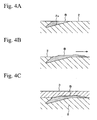
- a composition B of a relatively soft second phase which is included in the copper alloy layer 2 and is exposed at the surface as shown in Fig. 4A , is spread by a cutting tool as shown in Fig. 4B , whereby the composition B of the second phase thinly adheres to the surface of the copper alloy layer 2.
- the composition B of the second phase is dispersed in the copper alloy layer 2 in a particle state that is not solid solved, and the composition B of the second phase is exposed at the surface.
- Fig. 4B shows an arrow indicating a cutting direction to which a cutting tool moves.
- the composition B of the second phase exists in an interface between the copper alloy layer 2 and the overlay layer 3.
- the overlay layer 3 basically does not have a large bonding strength with respect to the composition B of the second phase. Therefore, when the composition B of the second phase is spread over the surface of the copper alloy layer 2 by machining, and the area of the composition B of the second phase at the interface is increased, the rate of insufficient bonding strength is increased as the area is increased. If an overlay layer with portions having insufficient bonding strength in this manner is included, the overlay layer easily detaches from the copper alloy layer. Specifically, in hard conditions such as high temperature and high surface pressure, which occur in a recent high-powered engine, the overlay layer easily comes off by tangential force of a surface of a shaft that slides and rotates at high speed, whereby seizing may occur.
- An object of the present invention is to provide a sliding member with an overlay layer in which a bonding strength with respect to a copper alloy layer including a second phase composition is greatly improved.
- the sliding member is superior in a fitting characteristic and is specifically superior in an anti-seizing characteristic and a fatigue resistance.
- the present invention provides a sliding member having an overlay layer formed on a copper alloy layer including a second phase composition.
- the copper alloy layer and the overlay layer have an interface therebetween, and the second phase composition is included in the copper alloy layer except the interface.
- the second phase composition which does not have a sufficient bonding strength with respect to the overlay layer, does not exist in the interface between the copper alloy layer and the overlay layer. Therefore, the entirety of the bonded surface of the overlay layer with respect to the copper alloy layer is bonded to only a matrix of the copper alloy layer. Accordingly, the bonding strength of the overlay layer with respect to the copper alloy layer including the second phase composition is further improved, whereby the sliding member has a superior anti-seizing characteristic and a superior fatigue resistance.
- the copper alloy layer is electrolyzed in a step of acid pickling of a pretreatment of plating and is then ultrasonically cleaned in a step of water washing, before an overlay layer is formed on the copper alloy layer by plating, whereby the composition B of the second phase shown in Fig. 4A detaches from the surface of the copper alloy layer 2.
- the second phase composition is removed from the surface of the copper alloy layer in such a manner, and then an overlay layer is formed on the surface of the copper alloy layer, whereby an interface between the copper alloy layer and the overlay layer, which does not include the second phase composition, is obtained.
- a concave portion (indicated by reference numeral 2a in Fig. 4A ), in which the second phase composition was contained, appears at the surface of the copper alloy layer, from which the second phase composition was removed.
- a plated composition of the overlay layer fills the concave portion, thereby obtaining a so-called “anchor effect". Accordingly, the bonding strength of the overlay layer with respect to the copper alloy layer is secondarily further improved.
- the second phase composition which is included in the copper alloy layer and is not solid solved, is dispersed in a particle state in the copper alloy layer without being exposed at the interface between the copper alloy layer and the overlay layer.
- a facing member slides on the exposed surface, and then the second phase composition in the copper alloy layer appears at the surface.
- the facing member slides on the second phase composition at the surface, whereby sliding characteristics are securely obtained.
- Bi or Pb may be mentioned.
- the content of the second phase composition in the copper alloy layer is less than 1 mass %, the anti-seizing characteristic is not reliably obtained under conditions in which the overlay layer is worn and the copper alloy layer is exposed.
- the content of the second phase composition is greater than 20 mass %, the strength of the copper alloy layer is decreased. Therefore, the content of the second phase composition in the copper alloy layer is preferably in a range of 1 to 20 mass %.
- the second phase composition included in the copper alloy layer does not exist at the interface between the copper alloy layer of the base and the overlay layer. Therefore, the bonding strength of the overlay layer with respect to the copper alloy layer is greatly improved, whereby a superior anti-seizing characteristic and a superior fatigue resistance are obtained.
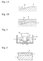
- Fig. 1A shows a condition in which a composition B of a second phase exposed at a surface of a copper alloy layer 2 shown in Fig. 4A is removed and the surface has a concave portion 2a.
- an overlay layer 3 made of Bi, Pb, or an alloy primarily made of Bi or Pb is formed on the surface of the copper alloy layer 2 by plating.
- the copper alloy layer 2 is formed on a surface of a backing metal (not shown in the figures), thereby forming a bearing metal (sliding member) having three layers in which the overlay layer 3 and the copper alloy layer 2 are laminated on the backing metal.
- a plate-shaped backing metal having a surface formed with the copper alloy layer 2 is formed into a semicircular shape so that the copper alloy layer 2 is at the side of an inner circumferential surface by pressing. Then, the overlay layer 3 is formed on the copper alloy layer 2, whereby a bearing metal is obtained. In this bearing metal, a shaft of a facing member rotates and slides on the overlay layer 3.
- the copper alloy layer 2 for a bearing metal which is a base of the overlay layer 3, is formed on a backing metal made of a low-carbon steel so as to have an appropriate thickness.
- the copper alloy layer 2 is suitably formed on the backing metal by sintering method, in which a copper alloy powder is spread on the backing metal and the backing metal and the copper alloy powder are diffusion bonded by heating to high temperature.
- the composition of the copper alloy layer 2 for example, Cu-Bi-Sn or Cu-Pb-Sn may be mentioned.
- the overlay layer 3 as described above, Bi, Pb, a Bi-Sn alloy primarily made of Bi, or a Pb-Sn alloy primarily made of Pb may be used.
- the total thickness of the copper alloy layer 2 and the overlay layer 3 may be approximately 300 ⁇ m, for example, and the overlay layer 3 may have a thickness of approximately 10 ⁇ m, for example.
- Particles of Bi or Pb which do not solid solve, are dispersed in the copper alloy layer 2 at 1 to 20 mass % as the second phase composition.
- the surface of the copper alloy layer 2 is machined and is flat finished after the copper alloy layer 2 is formed into a shape of a bearing metal, and then an overlay layer 3 is formed thereon.
- a pretreatment of plating and a treatment of removing the second phase composition exposed at the surface of the copper alloy layer 2 are performed before the formation of the overlay layer 3 and after the machining.
- the steps of solvent degreasing, water washing, alkali electrolytic degreasing, and water washing are performed in this order.
- the treatment of removing the second phase composition is performed by electrolytic pickling as pickling and subsequent ultrasonic water washing, after the pretreatment of the plating.
- the second phase composition is removed from the surface of the copper alloy layer 2 as shown in Fig. 1A , and a concave portion 2a, in which the second phase composition is contained, appears at the surface.
- an overlay layer 3 is formed on the surface of the copper alloy layer 2 by electroplating, whereby a bearing metal is obtained.
- the second phase composition included in the copper alloy layer 2 does not exist at the interface between the copper alloy layer 2 and the overlay layer 3. Therefore, the entirety of the bonding surface of the overlay layer 3 with respect to the copper alloy layer 2 is bonded to only the matrix of the copper alloy layer 2.
- the second phase composition is a composition that may decrease the bonding strength of the overlay layer 3 with respect to the copper alloy layer 2, and the overlay layer 3 is not bonded to the second phase composition in this embodiment. Therefore, the bonding strength of the overlay layer 3 with respect to the copper alloy layer 2 including the second phase composition is greatly improved, whereby a superior anti-seizing characteristic and a superior fatigue resistance are obtained. Since a shaft rotates and slides on the overlay layer 3, a fitting characteristic that a baring metal is expected to have is reliably obtained.
- the concave portion 2a in which the second phase composition was contained, appears at the surface of the copper alloy layer 2, from which the second phase composition was removed, and a plated composition of the overlay layer 3 fills the concave portion 2a, whereby an anchor effect is obtained. Therefore, the bonding strength of the overlay layer 3 with respect to the copper alloy layer 2 is secondarily further improved.
- a method of removing the second phase composition exposed at the surface of the copper alloy layer 2 after machining of the copper alloy layer 2 is not limited to the treatment of electrolytic pickling and subsequent ultrasonic water washing, and any method which can remove the second phase composition may be used.
- a copper alloy layer made of a Cu-Bi-Sn alloy was formed on a surface of a backing metal, which was made of a low-carbon steel, by sintering, and the backing metal was formed in a semicircular shape by pressing so that the copper alloy layer was at the side of an inner circumferential surface. Then, the surface of the copper alloy layer was machined and was flat finished, and the surface of the copper alloy layer was subjected to a pretreatment of plating by solvent degreasing, water washing, alkali electrolytic degreasing, and water washing, in this order. Next, the surface of the copper alloy layer was subjected to a treatment of removing the second phase composition by electrolytic pickling and ultrasonic water washing. Then, an overlay layer was formed by plating Bi on the copper alloy layer, and a three-layered structure was thereby formed, whereby test specimens of a bearing metal of a practical example 1 were obtained.
- Test specimens of a bearing metal of Practical Example 2 were obtained in the same manner as in the Practical Example 1, except that the copper alloy layer was made of a Cu-Pb-Sn alloy and the composition of the overlay layer was Pb.
- Test specimens of a bearing metal of Comparative Example 1 were obtained in the same manner as in the Practical Example 1, except that the treatment for removing the second phase composition was not performed on the surface of the copper alloy layer.
- Test specimens of a bearing metal of Comparative Example 2 were obtained in the same manner as in the Practical Example 2, except that the treatment for removing the second phase composition was not performed on the surface of the copper alloy layer.
- a holder 11 was placed on the bottom of a container 10 filled with water, and a test specimen P was held by the holder 11 so that the inner circumferential surface formed with the overlay layer faced upward. Then, a horn 12 was immersed in the water W, and a top of the horn 12 was brought close to the overlay layer so that the distance therebetween was 0.5 mm, and ultrasonic waves of 19000 Hz were generated by the horn 12. The ultrasonic waves were generated for 3 minutes, and the vibrations of the ultrasonic waves were applied to the overlay layer, whereby whether the overlay layer detached from the copper alloy layer of the base or not was investigated.
- a pair of the test specimens was inserted into a cylindrical baring member so as to form a bearing, and a shaft made of a medium-carbon steel S48C was inserted into the bearing. Then, the shaft was rotated at a circumferential speed of 20 m/sec while a lubricant, at approximately 100 °C, was supplied to the bearing at 500 cc/min. The shaft was rotated until seizing occurred, while radial load was increased by 5 MPa in each 10-minute interval, and a maximum surface pressure just before seizing was measured and was compared.
- the overlay layers of the test specimens of the Practical Examples 1 and 2 did not detach to a significant extent, and it was confirmed that the bearing metals of the Practical Examples 1 and 2 can be applied in practical use.
- the overlay layers of the test specimens of the Comparative Examples 1 and 2 did detach to a significant extent, and it was confirmed that the bearing metals of the Comparative Examples 1 and 2 are insufficient in practical use.
- the seizing test when the Practical Examples 1 and 2 were compared with the Comparative Examples 1 and 2, the maximum surface pressures of the Practical Examples, at which seizing does not occur, were improved by 24 % from those of the Comparative Examples. According to these results, the bonding strength obtained by the present invention was greatly improved compared to that in conventional cases.
- the sliding member of the present invention may be suitably used for slide bearings incorporated into crankshafts and connecting rods for automobile engines.
- a sliding member comprises an overlay layer that is formed on a copper alloy layer including a second phase composition.
- the copper alloy layer and the overlay layer have an interface therebetween, and the second phase composition is included in the copper alloy layer except the interface.
Landscapes
- Engineering & Computer Science (AREA)
- General Engineering & Computer Science (AREA)
- Mechanical Engineering (AREA)
- Sliding-Contact Bearings (AREA)
- Powder Metallurgy (AREA)
- Electroplating Methods And Accessories (AREA)
Claims (4)
- Organe coulissant comprenant une couche de recouvrement qui est formée sur une couche en alliage de cuivre,
dans lequel la couche en alliage de cuivre et la couche de recouvrement ont une interface entre elles,
l'organe coulissant est caractérisé en ce que la couche en alliage de cuivre comporte une composition de seconde phase, la composition de seconde phase dans l'interface étant éliminée de celle-ci de façon à former des concavités,
et un matériau de la couche de recouvrement est chargé dans les concavités. - Organe coulissant selon la revendication 1, dans lequel la composition de seconde phase est une composition de Bi et Pb.
- Organe coulissant selon la revendication 1 ou 2, dans lequel la couche en alliage de cuivre comprend de 1 à 20 % en masse de la composition de seconde phase.
- Organe coulissant selon l'une des revendications 1 à 3, dans lequel la couche de recouvrement est composée d'un élément parmi Bi, Pb, un alliage de Bi-Sn comprenant principalement du Bi, et un alliage de Pb-Sn comprenant principalement du Pb.
Applications Claiming Priority (1)
| Application Number | Priority Date | Filing Date | Title |
|---|---|---|---|
| JP2008045490A JP4994266B2 (ja) | 2008-02-27 | 2008-02-27 | 摺動部材 |
Publications (2)
| Publication Number | Publication Date |
|---|---|
| EP2095940A1 EP2095940A1 (fr) | 2009-09-02 |
| EP2095940B1 true EP2095940B1 (fr) | 2011-09-28 |
Family
ID=40552071
Family Applications (1)
| Application Number | Title | Priority Date | Filing Date |
|---|---|---|---|
| EP09002366A Revoked EP2095940B1 (fr) | 2008-02-27 | 2009-02-19 | Élément coulissant |
Country Status (3)
| Country | Link |
|---|---|
| US (1) | US20090214887A1 (fr) |
| EP (1) | EP2095940B1 (fr) |
| JP (1) | JP4994266B2 (fr) |
Families Citing this family (5)
| Publication number | Priority date | Publication date | Assignee | Title |
|---|---|---|---|---|
| JP6091961B2 (ja) | 2013-03-29 | 2017-03-08 | 大豊工業株式会社 | 摺動部材およびすべり軸受 |
| JP5981868B2 (ja) * | 2013-03-29 | 2016-08-31 | 大豊工業株式会社 | 摺動部材およびすべり軸受 |
| JP6247989B2 (ja) * | 2014-04-15 | 2017-12-13 | 大豊工業株式会社 | 摺動部材およびすべり軸受 |
| JP6242957B2 (ja) * | 2016-07-29 | 2017-12-06 | 大豊工業株式会社 | 摺動部材およびすべり軸受 |
| JP6242965B2 (ja) * | 2016-08-24 | 2017-12-06 | 大豊工業株式会社 | 摺動部材およびすべり軸受 |
Family Cites Families (18)
| Publication number | Priority date | Publication date | Assignee | Title |
|---|---|---|---|---|
| US3403010A (en) * | 1966-02-14 | 1968-09-24 | Clevite Corp | Multilayer bearing having a base of steel and a surface layer of a lead alloy |
| DE3619881A1 (de) * | 1986-06-13 | 1987-12-17 | Wmf Wuerttemberg Metallwaren | Verfahren und mittel zur verbesserung der haftfestigkeit eines metallueberzugs auf einem durch spangebende verformung hergestellten, bleihaltigen messing-formkoerper |
| JP2805543B2 (ja) * | 1990-10-30 | 1998-09-30 | 本田技研工業株式会社 | すべり軸受 |
| JP2834662B2 (ja) * | 1993-12-27 | 1998-12-09 | 大同メタル工業株式会社 | 多層すべり軸受材料及びその製造方法 |
| JP3108363B2 (ja) * | 1996-03-25 | 2000-11-13 | エヌデーシー株式会社 | インジウムを含む銅−鉛系合金軸受ならびにその製造方法 |
| JPH10205539A (ja) * | 1997-01-22 | 1998-08-04 | Daido Metal Co Ltd | 銅系すべり軸受 |
| JP3249774B2 (ja) | 1997-06-05 | 2002-01-21 | トヨタ自動車株式会社 | 摺動部材 |
| JPH11293368A (ja) * | 1998-04-07 | 1999-10-26 | Daido Metal Co Ltd | 銅系摺動合金 |
| JP3421724B2 (ja) | 1999-09-13 | 2003-06-30 | 大同メタル工業株式会社 | 銅系摺動材料 |
| JP3607543B2 (ja) * | 1999-09-14 | 2005-01-05 | 大同メタル工業株式会社 | すべり軸受 |
| JP2001082481A (ja) * | 1999-09-14 | 2001-03-27 | Daido Metal Co Ltd | すべり軸受及びその製造方法 |
| JP2001099158A (ja) * | 1999-09-29 | 2001-04-10 | Daido Metal Co Ltd | すべり軸受 |
| JP3643272B2 (ja) * | 1999-10-12 | 2005-04-27 | 大同メタル工業株式会社 | すべり軸受 |
| JP3507388B2 (ja) * | 2000-02-08 | 2004-03-15 | 大同メタル工業株式会社 | 銅系摺動材料 |
| JP3754353B2 (ja) * | 2001-11-15 | 2006-03-08 | 大同メタル工業株式会社 | 複合めっき被膜付き摺動部材 |
| JP4547577B2 (ja) * | 2004-11-30 | 2010-09-22 | 大豊工業株式会社 | 摺動材料とその製造方法 |
| JP4054813B2 (ja) * | 2005-04-08 | 2008-03-05 | 株式会社共立 | アルミニウム合金製素材のめっき方法 |
| AT502506B1 (de) * | 2006-03-30 | 2007-04-15 | Miba Gleitlager Gmbh | Lagerelement |
-
2008
- 2008-02-27 JP JP2008045490A patent/JP4994266B2/ja active Active
-
2009
- 2009-02-18 US US12/388,389 patent/US20090214887A1/en not_active Abandoned
- 2009-02-19 EP EP09002366A patent/EP2095940B1/fr not_active Revoked
Also Published As
| Publication number | Publication date |
|---|---|
| US20090214887A1 (en) | 2009-08-27 |
| EP2095940A1 (fr) | 2009-09-02 |
| JP2009203504A (ja) | 2009-09-10 |
| JP4994266B2 (ja) | 2012-08-08 |
Similar Documents
| Publication | Publication Date | Title |
|---|---|---|
| JP6326426B2 (ja) | 滑り軸受複合材料 | |
| US4696867A (en) | Aluminum based bearing alloys | |
| US6863994B2 (en) | Sliding bearing and method of manufacturing the same | |
| US4927715A (en) | Overlay alloy used for a surface layer of sliding material | |
| EP2095940B1 (fr) | Élément coulissant | |
| EP2048391A2 (fr) | Roulement coulissant | |
| Totten | Friction, lubrication, and wear technology | |
| JP2575814B2 (ja) | 多層摺動材料 | |
| US8053088B2 (en) | Slide member | |
| JPH01307512A (ja) | 多層アルミニウム合金すべり軸受およびその製造方法 | |
| US6431758B1 (en) | Sliding-contact bearings with diamond particles | |
| JP3754315B2 (ja) | 複層摺動材料 | |
| KR20050002597A (ko) | 슬라이딩 부재 | |
| RU2299790C1 (ru) | Способ обработки вкладышей подшипников скольжения | |
| EP0186414B1 (fr) | Palier lisse | |
| US4591536A (en) | Plain bearing and method of manufacture | |
| JP2002106565A (ja) | 複合スライドプレート | |
| KR101398616B1 (ko) | 슬라이딩 부재 | |
| JP3754353B2 (ja) | 複合めっき被膜付き摺動部材 | |
| JPH04331817A (ja) | 複合めっき皮膜を有するすべり軸受 | |
| CN107636330B (zh) | 滑动轴承和方法 | |
| US5770323A (en) | Bearings | |
| JP2000120694A (ja) | 多層すべり軸受 | |
| Totten | Friction and Wear of Sliding Bearing Materials |
Legal Events
| Date | Code | Title | Description |
|---|---|---|---|
| PUAI | Public reference made under article 153(3) epc to a published international application that has entered the european phase |
Free format text: ORIGINAL CODE: 0009012 |
|
| 17P | Request for examination filed |
Effective date: 20090219 |
|
| AK | Designated contracting states |
Kind code of ref document: A1 Designated state(s): AT BE BG CH CY CZ DE DK EE ES FI FR GB GR HR HU IE IS IT LI LT LU LV MC MK MT NL NO PL PT RO SE SI SK TR |
|
| AX | Request for extension of the european patent |
Extension state: AL BA RS |
|
| 17Q | First examination report despatched |
Effective date: 20090821 |
|
| AKX | Designation fees paid |
Designated state(s): DE GB |
|
| GRAP | Despatch of communication of intention to grant a patent |
Free format text: ORIGINAL CODE: EPIDOSNIGR1 |
|
| GRAS | Grant fee paid |
Free format text: ORIGINAL CODE: EPIDOSNIGR3 |
|
| GRAA | (expected) grant |
Free format text: ORIGINAL CODE: 0009210 |
|
| AK | Designated contracting states |
Kind code of ref document: B1 Designated state(s): DE GB |
|
| REG | Reference to a national code |
Ref country code: GB Ref legal event code: FG4D |
|
| REG | Reference to a national code |
Ref country code: DE Ref legal event code: R096 Ref document number: 602009002737 Country of ref document: DE Effective date: 20111124 |
|
| PGFP | Annual fee paid to national office [announced via postgrant information from national office to epo] |
Ref country code: DE Payment date: 20111215 Year of fee payment: 4 |
|
| PLBI | Opposition filed |
Free format text: ORIGINAL CODE: 0009260 |
|
| PLAX | Notice of opposition and request to file observation + time limit sent |
Free format text: ORIGINAL CODE: EPIDOSNOBS2 |
|
| 26 | Opposition filed |
Opponent name: FEDERAL-MOGUL WIESBADEN GMBH Effective date: 20120628 Opponent name: KS GLEITLAGER GMBH Effective date: 20120627 Opponent name: MIBA GLEITLAGER GMBH Effective date: 20120628 |
|
| REG | Reference to a national code |
Ref country code: DE Ref legal event code: R026 Ref document number: 602009002737 Country of ref document: DE Effective date: 20120627 |
|
| PLAF | Information modified related to communication of a notice of opposition and request to file observations + time limit |
Free format text: ORIGINAL CODE: EPIDOSCOBS2 |
|
| PLBB | Reply of patent proprietor to notice(s) of opposition received |
Free format text: ORIGINAL CODE: EPIDOSNOBS3 |
|
| PLAB | Opposition data, opponent's data or that of the opponent's representative modified |
Free format text: ORIGINAL CODE: 0009299OPPO |
|
| R26 | Opposition filed (corrected) |
Opponent name: KS GLEITLAGER GMBH Effective date: 20120627 |
|
| GBPC | Gb: european patent ceased through non-payment of renewal fee |
Effective date: 20130219 |
|
| PG25 | Lapsed in a contracting state [announced via postgrant information from national office to epo] |
Ref country code: DE Free format text: LAPSE BECAUSE OF NON-PAYMENT OF DUE FEES Effective date: 20130903 |
|
| REG | Reference to a national code |
Ref country code: DE Ref legal event code: R119 Ref document number: 602009002737 Country of ref document: DE Effective date: 20130903 |
|
| RDAF | Communication despatched that patent is revoked |
Free format text: ORIGINAL CODE: EPIDOSNREV1 |
|
| PG25 | Lapsed in a contracting state [announced via postgrant information from national office to epo] |
Ref country code: GB Free format text: LAPSE BECAUSE OF NON-PAYMENT OF DUE FEES Effective date: 20130219 |
|
| RDAG | Patent revoked |
Free format text: ORIGINAL CODE: 0009271 |
|
| STAA | Information on the status of an ep patent application or granted ep patent |
Free format text: STATUS: PATENT REVOKED |
|
| 27W | Patent revoked |
Effective date: 20140126 |