EP2095906B1 - Dispositif de traitement de finition mécanique de surfaces de roulement sur des anneaux de palier à roulement - Google Patents
Dispositif de traitement de finition mécanique de surfaces de roulement sur des anneaux de palier à roulement Download PDFInfo
- Publication number
- EP2095906B1 EP2095906B1 EP20090000410 EP09000410A EP2095906B1 EP 2095906 B1 EP2095906 B1 EP 2095906B1 EP 20090000410 EP20090000410 EP 20090000410 EP 09000410 A EP09000410 A EP 09000410A EP 2095906 B1 EP2095906 B1 EP 2095906B1
- Authority
- EP
- European Patent Office
- Prior art keywords
- slide
- output shaft
- movement
- pin
- carriage
- Prior art date
- Legal status (The legal status is an assumption and is not a legal conclusion. Google has not performed a legal analysis and makes no representation as to the accuracy of the status listed.)
- Not-in-force
Links
- 230000033001 locomotion Effects 0.000 claims description 48
- 239000004575 stone Substances 0.000 claims description 25
- 230000003534 oscillatory effect Effects 0.000 claims description 11
- 238000003754 machining Methods 0.000 description 17
- 230000010355 oscillation Effects 0.000 description 8
- 238000005096 rolling process Methods 0.000 description 8
- 230000005540 biological transmission Effects 0.000 description 3
- 238000010002 mechanical finishing Methods 0.000 description 3
- 230000000694 effects Effects 0.000 description 2
- 230000008030 elimination Effects 0.000 description 1
- 238000003379 elimination reaction Methods 0.000 description 1
- 230000002093 peripheral effect Effects 0.000 description 1
Images


Classifications
-
- B—PERFORMING OPERATIONS; TRANSPORTING
- B24—GRINDING; POLISHING
- B24B—MACHINES, DEVICES, OR PROCESSES FOR GRINDING OR POLISHING; DRESSING OR CONDITIONING OF ABRADING SURFACES; FEEDING OF GRINDING, POLISHING, OR LAPPING AGENTS
- B24B19/00—Single-purpose machines or devices for particular grinding operations not covered by any other main group
- B24B19/02—Single-purpose machines or devices for particular grinding operations not covered by any other main group for grinding grooves, e.g. on shafts, in casings, in tubes, homokinetic joint elements
- B24B19/06—Single-purpose machines or devices for particular grinding operations not covered by any other main group for grinding grooves, e.g. on shafts, in casings, in tubes, homokinetic joint elements for grinding races, e.g. roller races
-
- B—PERFORMING OPERATIONS; TRANSPORTING
- B24—GRINDING; POLISHING
- B24B—MACHINES, DEVICES, OR PROCESSES FOR GRINDING OR POLISHING; DRESSING OR CONDITIONING OF ABRADING SURFACES; FEEDING OF GRINDING, POLISHING, OR LAPPING AGENTS
- B24B35/00—Machines or devices designed for superfinishing surfaces on work, i.e. by means of abrading blocks reciprocating with high frequency
Definitions
- the invention relates to a device for mechanical finishing of running surfaces of rolling bearing rings, in particular for the machining of running surfaces on cylindrical roller and tapered roller bearings. Finishing is an additional processing step to improve the roughness and dimensional accuracy of machined surfaces. Finishing usually involves a chip removal of a few micrometers. During finishing, the workpiece to be machined is driven in rotation. The processing takes place by means of a finishing stone, which performs oscillating movements during processing. The oscillation path and the oscillation frequency have an effect on the final result.
- a device for finish machining of rolling bearing rings is made EP 0 936 028 B1 known.
- the known device comprises two linearly adjustable in the X-, Y-direction carriages and arranged on one of the carriage pivoting device with a stone holder for a finishing stone.
- the positioning movements in X-, Y-direction and the pivoting movements of the stone holder are controllable depending on the workpiece profile to be machined.
- the finishing stone is movable over the workpiece surface to be machined and follows the contour of the workpiece surface.
- the running surfaces can be edited on bearing rings of spherical roller bearings, cylindrical roller bearings and tapered roller bearings.
- the invention has for its object to provide a device for universal finish machining of bearing rings for cylindrical roller and tapered roller bearings, which is structurally simple and is characterized in that the to be moved for an oscillatory movement of a finishing stone masses are small.
- the Oszillationsweg and the oscillation frequency with which the finishing stone is moved over the workpiece surface to be machined, should be variable fixable.
- the invention relates to a device according to claim 1 for the mechanical finishing of running surfaces of rolling bearing rings.
- the object is achieved in that the eccentric drive has an NC-controlled servo drive, the output shaft reversing movements with freely programmable pivot angle executes that the carriage guide is disposed on a rotary plate which is rotatably mounted about a coaxial to the output shaft axis on the support, and that the tool carrier has an adjusting device for linear adjustment of the stone holder transversely to the direction of movement of the carriage.
- the workpiece to be machined is clamped to a workpiece spindle and set in rotation during finishing.
- the spindle axis of the tool spindle and the direction of movement of the carriage of the device according to the invention are aligned in parallel.
- the eccentric drive for generating oscillatory movements of the carriage has a highly dynamic servo drive, which performs reversing rotational movements.
- the swivel angle of the servo drive is freely programmable. Since the output shaft of the servomotor acts by an eccentric on the slide, changes with the tilt angle of their reversing movements at the same time the linear stroke of the carriage. The linear stroke of the carriage and the pivot angle of the output shaft are in a fixed relationship to each other. By the motor speed of the servo drive, the oscillation frequency of the linear stroke is also variable. Both the swing angle for the reversing motions of the output shaft and the motor speed of the servo drive can be continuously changed during a finish machining to affect the finishing. By an appropriate control of the servo motor oscillatory movements with short stroke or long stroke and also with different frequencies can be generated. Furthermore, long stroke oscillatory motions and short stroke oscillatory motions may be superimposed.
- a connecting piece is connected to the output shaft of the servo drive, which has a staggered to the shaft axis of the output shaft arranged pin.
- the pin cooperates with sliding surfaces on the carriage, which transmit a component of the pin movement acting in the direction of movement of the carriage onto the carriage and permit a pin movement transverse to the direction of movement of the carriage.
- two stop elements are preferably attached to the carriage, which are arranged on both sides of the pin with a height offset opposite and having a planar gate surface, which rests against each one arranged on the pin bearings.
- the device according to the invention has a modular structure and can be retrofitted in a few steps so that the device can be used by using the servo drive for finish machining of roller bearing rings for ball bearings.
- the rotary plate, the carriage assembly and the connector for transmitting the oscillatory movements of the output shaft form a replaceable module.
- the tool carrier is directly or indirectly connected by means of an adapter to the output shaft of the servo drive.
- the reversing movements of the motor are transmitted as pivotal movements on the stone holder, so that the device can also be used for finishing of spherically curved surfaces.
- Users who use the device according to the invention first for machining roller bearing rings for ball bearings want to use the device can subsequently by installing the assembly described also for processing Zylinderrollenlagem and tapered roller bearings use.
- the entire device can be connected to an adjusting device, for. B. to a carriage, are connected, with which the device between a working position and a second position in which the finishing stone is spaced from the workpiece surface, is movable. If the device takes the second position, a trouble-free workpiece change is possible.
- the carrier is therefore fastened by means of a clamping device to push rods, which are displaceable with a predetermined travel between two positions.
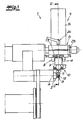
- the device 1 shown in the figures is used for mechanical finishing of raceways on rolling bearing rings for cylindrical roller bearings and tapered roller bearings.
- the device 1 is associated with a tool spindle 2 in which a workpiece 3 to be machined is tensioned and can be driven in rotation about the spindle axis 4 during finish machining.
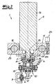
- the basic structure of the device 1 includes a carrier 5, a carriage assembly 6, which has a carriage 7 and a slide guide 8 for linear guidance of the carriage 7, an eccentric 9 for generating oscillatory movements of the carriage 7, a tool carrier 10 fastened to the carriage 7 and a tool holder 10 connected to the stone holder 11 with a finishing stone 12.
- the tool carrier 10 has an adjusting device 13 for linear adjustment of the stone holder 11 transversely to the direction of movement of the carriage 7. During finish machining, the finishing stone 12 bears against the peripheral surface of the rotationally driven workpiece 3 with a predetermined pressure force.
- the finishing stone 12 executes oscillatory movements, wherein the oscillation path and the oscillation frequency are variable.
- the eccentric 9 an NC-controlled servo drive 14, z. an AC servomotor, on.
- the output shaft 15 of the servo drive 14 performs reversing rotational movements, wherein the pivot angle ⁇ is freely programmable.
- the reversing rotational movement is transmitted to the carriage 7 by an eccentric arrangement 16.
- the pivot angle ⁇ By adjusting the pivot angle ⁇ , the stroke of the carriage 7 is variable.
- the oscillation frequency of the oscillating movement performed by the finishing stone 12 is also controllable.
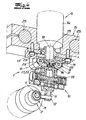
- the carriage guide 8 is arranged on a rotary plate 17, which is fastened to the output shaft 15 coaxial axis 18 rotatable on the carrier 5.
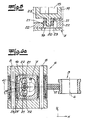
- the axis of rotation 4 of the workpiece and slide guide 8 are aligned parallel to each other ( Fig. 6a ).
- the rotary plate 17 is adjusted by an angle ⁇ , so that the carriage guide 8 is aligned parallel to the cone / conical surface to be machined ( Fig. 6b ).
- a connecting piece 19 is connected, which has a shaft 20 of the output shaft 15 offset staggered pin 20 has.
- the pin 20 cooperates with slide surfaces 21 on the carriage 7, which transmit a acting in the direction of movement of the carriage 7 component of the pin movement on the carriage 7 and allow a pin movement transverse to the direction of movement of the carriage 7.
- two stop elements 22 are fixed, which are arranged on both sides of the pin 20 with a height offset opposite. They each have a planar sliding surface 21 which bears against a roller bearing 23, 23 'arranged on the journal.
- each rolling bearing On the pin 20, two rolling bearings 23, 23 'are arranged, each rolling bearing a stop element 22 is associated.
- a play-free motion transmission in the X direction is possible, while the rolling bearings roll in the transverse direction Y on the crank surfaces 21 and thereby permit a journal movement transversely to the direction of movement of the carriage.
- the representations in the Fig. 1 and 2 If one deduces that the carrier 5 is fixed by means of a clamping device 24 to push rods 25 which are displaceable with a predetermined travel between two positions. In the working position shown in the figures, the finishing stone 12 bears against the workpiece 3 to be machined. In a second position, not shown, the finishing stone is spaced from the machined workpiece surface, so that a workpiece change is possible.
- the rotary plate 17, the carriage assembly 6 and the connector 19 for transmitting reversing movements of the output shaft 15 form a replaceable module.
- the tool carrier 10 can be connected directly or by means of an adapter to the output shaft 15 of the servo drive 14 and the device 1 can also be used for machining of spherical surfaces, in particular for machining bearing rings for ball bearings.
Landscapes
- Engineering & Computer Science (AREA)
- Mechanical Engineering (AREA)
- Grinding And Polishing Of Tertiary Curved Surfaces And Surfaces With Complex Shapes (AREA)
- Constituent Portions Of Griding Lathes, Driving, Sensing And Control (AREA)
Claims (5)
- Dispositif d'usinage mécanique de finition de surfaces de roulement d'anneaux à paliers à roulements, comportant
un support (5),
un système de chariot (6) présentant un chariot (7) ainsi qu'un guide de chariot (8) pour le guidage linéaire du chariot,
un organe de commande excentrique (9) fixé au support (5) pour générer des mouvements d'oscillation du chariot (7),
un porte-outil (10) fixé au chariot (7) et
un porte-meule (11) raccordé au porte-outil (10) et doté d'une meule de finition (12),
caractérisé en ce que le disque excentrique (9) présente une servocommande contrôlée par CN dont l'arbre mené (15) exécute des mouvements d'inversion suivant un angle de pivotement (α) programmable à volonté, que le guide de chariot (8) est disposé sur un plateau tournant qui est fixé de manière pivotable sur le support (5) autour d'un axe (18) coaxial à l'arbre mené et que le porte-outil (10) présente un dispositif de réglage (13) pour le réglage linéaire du porte-meule (11) transversalement par rapport au sens de mouvement du chariot (7). - Dispositif selon la revendication 1, caractérisé en ce qu'est raccordée à l'arbre mené (15) de la servocommande (14) une pièce de raccordement (19) qui présente un tourillon (20) disposé décalé par rapport à l'axe d'arbre de l'arbre mené (15) et que le tourillon (20) coopère au niveau du chariot (7) avec des surfaces à coulisse (21) qui transmettent au chariot une composante du mouvement du tourillon agissant dans le sens du mouvement du chariot (7) et permettent un mouvement du tourillon transversalement par rapport au sens de mouvement du chariot (7).
- Dispositif selon la revendication 2, caractérisé en ce que deux paliers à roulement (23, 23') sont disposés sur le tourillon (20) et qu'au chariot (7) sont fixés deux éléments de butée (22) qui sont disposés l'un en face de l'autre avec un décalage en hauteur des deux côtés du tourillon (20) et présentent une surface plane à coulisse (21) qui repose respectivement sur un des deux paliers à roulement (23, 23').
- Dispositif selon la revendication 2 ou 3, caractérisé en ce que le plateau tournant (17), le système de chariot (6) et la pièce de raccordement (19) destinée à transférer le mouvement d'oscillation de l'arbre mené (15) constituent un sous-ensemble interchangeable et que le porte-outil (10) est raccordable directement ou au moyen d'un adaptateur à l'arbre mené (15) de la servocommande (14).
- Dispositif selon une des revendications 1 à 4, caractérisé en ce que le support (5) est fixé au moyen d'un dispositif de serrage (24) à des barres de poussée (25) qui sont déplaçables entre deux positions sur une course de réglage prédéfinie.
Applications Claiming Priority (1)
| Application Number | Priority Date | Filing Date | Title |
|---|---|---|---|
| DE200810011215 DE102008011215B4 (de) | 2008-02-26 | 2008-02-26 | Vorrichtung zur mechanischen Finishbearbeitung von Laufflächen an Wälzlagerringen |
Publications (2)
| Publication Number | Publication Date |
|---|---|
| EP2095906A1 EP2095906A1 (fr) | 2009-09-02 |
| EP2095906B1 true EP2095906B1 (fr) | 2010-12-29 |
Family
ID=40749132
Family Applications (1)
| Application Number | Title | Priority Date | Filing Date |
|---|---|---|---|
| EP20090000410 Not-in-force EP2095906B1 (fr) | 2008-02-26 | 2009-01-14 | Dispositif de traitement de finition mécanique de surfaces de roulement sur des anneaux de palier à roulement |
Country Status (2)
| Country | Link |
|---|---|
| EP (1) | EP2095906B1 (fr) |
| DE (2) | DE102008011215B4 (fr) |
Families Citing this family (3)
| Publication number | Priority date | Publication date | Assignee | Title |
|---|---|---|---|---|
| CN105437023A (zh) * | 2015-12-31 | 2016-03-30 | 无锡诚石轴承有限公司 | 多沟道芯轴加工设备 |
| CN112917375B (zh) * | 2021-03-23 | 2022-06-10 | 中国航发哈尔滨轴承有限公司 | 一种轴承套圈精研加工油石摆动机构 |
| CN114378686A (zh) * | 2022-02-08 | 2022-04-22 | 浙江诚本轴承滚子有限公司 | 一种轴承滚子超精加工方法及超精机 |
Family Cites Families (5)
| Publication number | Priority date | Publication date | Assignee | Title |
|---|---|---|---|---|
| DE2413000A1 (de) * | 1974-03-18 | 1975-09-25 | Supfina Maschf Hentzen | Verfahren zur feinstbearbeitung zylindrischer oder kegeliger flaechen |
| DE19804885C5 (de) * | 1998-02-09 | 2004-07-15 | Supfina Grieshaber Gmbh & Co. Kg | Vorrichtung zum Superfinishen |
| JP4389554B2 (ja) * | 2002-12-19 | 2009-12-24 | 日本精工株式会社 | 超仕上げ装置 |
| JP2006255889A (ja) * | 2006-05-29 | 2006-09-28 | Jtekt Corp | 超仕上げ装置 |
| DE202007007704U1 (de) * | 2007-05-31 | 2007-09-06 | Thielenhaus Technologies Gmbh | Vorrichtung zur mechanischen Finishbearbeitung von Wälzlagerringen |
-
2008
- 2008-02-26 DE DE200810011215 patent/DE102008011215B4/de not_active Expired - Fee Related
-
2009
- 2009-01-14 DE DE200950000245 patent/DE502009000245D1/de active Active
- 2009-01-14 EP EP20090000410 patent/EP2095906B1/fr not_active Not-in-force
Also Published As
| Publication number | Publication date |
|---|---|
| DE102008011215A1 (de) | 2009-09-03 |
| EP2095906A1 (fr) | 2009-09-02 |
| DE102008011215B4 (de) | 2010-04-08 |
| DE502009000245D1 (de) | 2011-02-10 |
Similar Documents
| Publication | Publication Date | Title |
|---|---|---|
| EP2688710B1 (fr) | Dispositif de meuleuse a montage pivotant d'une unite de broche porte-meule et procede permettant de faire pivoter une unite de broche porte-meule sur une meuleuse | |
| DE68901850T2 (de) | Zur schleifbearbeitung von zylindrischen lagerflaechen von werkstuecken, insbesondere fuer die bearbeitung von kurbelwellen- und kurbelzapfen mittels bandschleifer. | |
| DE102007054897B4 (de) | Vorrichtung zur mechanischen Finishbearbeitung von sphärischen Flächen an rotationssymmetrischen Werkstücken | |
| DE102008046451B4 (de) | Vorrichtung zur mechanischen Finishbearbeitung von Umfangsflächen an rotationssymmetrischen Werkstücken, insbesondere Wälzlagerringen | |
| EP2338640A1 (fr) | Machine de meulage de pièces optiques, en particuliere de verres à lunettes en plastique | |
| EP1990133B1 (fr) | Agrégat de ponçage comme outil pour un dispositif de traitement | |
| DE102006058710A1 (de) | Werkzeugmaschine und Bearbeitungsvorrichtung zum Verfestigen von Radienübergängen an Kurbelwellen für Brennkraftmaschinen oder ähnlichen Werkstücken | |
| DE102009006797A1 (de) | Linsenbearbeitungsvorrichtung | |
| WO2015021565A1 (fr) | Machine permettant d'usiner des pièces | |
| DE3225977A1 (de) | Verfahren und vorrichtung zur feinstbearbeitung konvexer oder konkaver mantelflaechen rotationssymmetrischer werkstuecke, insbesondere von waelzlagerrollen | |
| DE102011089654B4 (de) | Verfahren zur drehbearbeitung von planschultern an den wangen einer kurbelwelle, verwendung des verfahrens zur komplettbearbeitung von kurbelwellenrohlingen sowie kurbelwellen-drehmaschine zur drehbearbeitung der planschultern | |
| EP1068917A2 (fr) | Dispositif et methode d' usinage de manetons de vilebrequins | |
| EP2095906B1 (fr) | Dispositif de traitement de finition mécanique de surfaces de roulement sur des anneaux de palier à roulement | |
| DE10030087B4 (de) | Verfahren und Vorrichtung zum Vermessen und Bearbeiten von Werkstücken | |
| DE2733070A1 (de) | Schleifmaschine | |
| DE102007021659A1 (de) | Flachschleifverfahren und Flachschleifmaschine | |
| DE102006036004A1 (de) | Vorrichtung und Verfahren zur Oberflächenbearbeitung von Werkstücken, insbesondere von metallischen oder keramischen Werkstücken | |
| DE202007007704U1 (de) | Vorrichtung zur mechanischen Finishbearbeitung von Wälzlagerringen | |
| DE102011078735B4 (de) | Finishvorrichtung | |
| DE102014102282B4 (de) | Finishwerkzeugträger und Finisheinheit | |
| DE2807268C3 (de) | Maschine zum Zentrierschleifen von optischen Linsen | |
| DE102008023081A1 (de) | Kontinuierliche Schleifvorrichtung | |
| DE102014106746A1 (de) | Vorrichtung zur mechanischen Endbearbeitung von Umfangsflächen an Werkstücken | |
| EP0867251B1 (fr) | Dispositif pour l'ajustage de la position exacte d'une lame de scie sur la surface périphérique des volants d'une scie à ruban | |
| DE102016014515A1 (de) | Vorrichtung zum Rotationsfinishen von Werkstückoberflächen |
Legal Events
| Date | Code | Title | Description |
|---|---|---|---|
| PUAI | Public reference made under article 153(3) epc to a published international application that has entered the european phase |
Free format text: ORIGINAL CODE: 0009012 |
|
| AK | Designated contracting states |
Kind code of ref document: A1 Designated state(s): AT BE BG CH CY CZ DE DK EE ES FI FR GB GR HR HU IE IS IT LI LT LU LV MC MK MT NL NO PL PT RO SE SI SK TR |
|
| AX | Request for extension of the european patent |
Extension state: AL BA RS |
|
| 17P | Request for examination filed |
Effective date: 20090811 |
|
| 17Q | First examination report despatched |
Effective date: 20091007 |
|
| AKX | Designation fees paid |
Designated state(s): DE FR GB IT |
|
| GRAP | Despatch of communication of intention to grant a patent |
Free format text: ORIGINAL CODE: EPIDOSNIGR1 |
|
| GRAC | Information related to communication of intention to grant a patent modified |
Free format text: ORIGINAL CODE: EPIDOSCIGR1 |
|
| GRAS | Grant fee paid |
Free format text: ORIGINAL CODE: EPIDOSNIGR3 |
|
| GRAA | (expected) grant |
Free format text: ORIGINAL CODE: 0009210 |
|
| AK | Designated contracting states |
Kind code of ref document: B1 Designated state(s): DE FR GB IT |
|
| REG | Reference to a national code |
Ref country code: GB Ref legal event code: FG4D Free format text: NOT ENGLISH |
|
| REF | Corresponds to: |
Ref document number: 502009000245 Country of ref document: DE Date of ref document: 20110210 Kind code of ref document: P |
|
| REG | Reference to a national code |
Ref country code: DE Ref legal event code: R096 Ref document number: 502009000245 Country of ref document: DE Effective date: 20110210 |
|
| PGFP | Annual fee paid to national office [announced via postgrant information from national office to epo] |
Ref country code: FR Payment date: 20110202 Year of fee payment: 3 Ref country code: DE Payment date: 20110124 Year of fee payment: 3 |
|
| PLBE | No opposition filed within time limit |
Free format text: ORIGINAL CODE: 0009261 |
|
| STAA | Information on the status of an ep patent application or granted ep patent |
Free format text: STATUS: NO OPPOSITION FILED WITHIN TIME LIMIT |
|
| 26N | No opposition filed |
Effective date: 20110930 |
|
| REG | Reference to a national code |
Ref country code: DE Ref legal event code: R097 Ref document number: 502009000245 Country of ref document: DE Effective date: 20110930 |
|
| PGFP | Annual fee paid to national office [announced via postgrant information from national office to epo] |
Ref country code: IT Payment date: 20120131 Year of fee payment: 4 |
|
| REG | Reference to a national code |
Ref country code: FR Ref legal event code: ST Effective date: 20120928 |
|
| PG25 | Lapsed in a contracting state [announced via postgrant information from national office to epo] |
Ref country code: DE Free format text: LAPSE BECAUSE OF NON-PAYMENT OF DUE FEES Effective date: 20120801 |
|
| REG | Reference to a national code |
Ref country code: DE Ref legal event code: R119 Ref document number: 502009000245 Country of ref document: DE Effective date: 20120801 |
|
| PG25 | Lapsed in a contracting state [announced via postgrant information from national office to epo] |
Ref country code: FR Free format text: LAPSE BECAUSE OF NON-PAYMENT OF DUE FEES Effective date: 20120131 |
|
| GBPC | Gb: european patent ceased through non-payment of renewal fee |
Effective date: 20130114 |
|
| PG25 | Lapsed in a contracting state [announced via postgrant information from national office to epo] |
Ref country code: GB Free format text: LAPSE BECAUSE OF NON-PAYMENT OF DUE FEES Effective date: 20130114 |
|
| PG25 | Lapsed in a contracting state [announced via postgrant information from national office to epo] |
Ref country code: IT Free format text: LAPSE BECAUSE OF NON-PAYMENT OF DUE FEES Effective date: 20130114 |