EP2095906B1 - Device for mechanically finishing baring surfaces of bearings - Google Patents
Device for mechanically finishing baring surfaces of bearings Download PDFInfo
- Publication number
- EP2095906B1 EP2095906B1 EP20090000410 EP09000410A EP2095906B1 EP 2095906 B1 EP2095906 B1 EP 2095906B1 EP 20090000410 EP20090000410 EP 20090000410 EP 09000410 A EP09000410 A EP 09000410A EP 2095906 B1 EP2095906 B1 EP 2095906B1
- Authority
- EP
- European Patent Office
- Prior art keywords
- slide
- output shaft
- movement
- pin
- carriage
- Prior art date
- Legal status (The legal status is an assumption and is not a legal conclusion. Google has not performed a legal analysis and makes no representation as to the accuracy of the status listed.)
- Not-in-force
Links
- 230000033001 locomotion Effects 0.000 claims description 48
- 239000004575 stone Substances 0.000 claims description 25
- 230000003534 oscillatory effect Effects 0.000 claims description 11
- 238000003754 machining Methods 0.000 description 17
- 230000010355 oscillation Effects 0.000 description 8
- 238000005096 rolling process Methods 0.000 description 8
- 230000005540 biological transmission Effects 0.000 description 3
- 238000010002 mechanical finishing Methods 0.000 description 3
- 230000000694 effects Effects 0.000 description 2
- 230000008030 elimination Effects 0.000 description 1
- 238000003379 elimination reaction Methods 0.000 description 1
- 230000002093 peripheral effect Effects 0.000 description 1
Images


Classifications
-
- B—PERFORMING OPERATIONS; TRANSPORTING
- B24—GRINDING; POLISHING
- B24B—MACHINES, DEVICES, OR PROCESSES FOR GRINDING OR POLISHING; DRESSING OR CONDITIONING OF ABRADING SURFACES; FEEDING OF GRINDING, POLISHING, OR LAPPING AGENTS
- B24B19/00—Single-purpose machines or devices for particular grinding operations not covered by any other main group
- B24B19/02—Single-purpose machines or devices for particular grinding operations not covered by any other main group for grinding grooves, e.g. on shafts, in casings, in tubes, homokinetic joint elements
- B24B19/06—Single-purpose machines or devices for particular grinding operations not covered by any other main group for grinding grooves, e.g. on shafts, in casings, in tubes, homokinetic joint elements for grinding races, e.g. roller races
-
- B—PERFORMING OPERATIONS; TRANSPORTING
- B24—GRINDING; POLISHING
- B24B—MACHINES, DEVICES, OR PROCESSES FOR GRINDING OR POLISHING; DRESSING OR CONDITIONING OF ABRADING SURFACES; FEEDING OF GRINDING, POLISHING, OR LAPPING AGENTS
- B24B35/00—Machines or devices designed for superfinishing surfaces on work, i.e. by means of abrading blocks reciprocating with high frequency
Definitions
- the invention relates to a device for mechanical finishing of running surfaces of rolling bearing rings, in particular for the machining of running surfaces on cylindrical roller and tapered roller bearings. Finishing is an additional processing step to improve the roughness and dimensional accuracy of machined surfaces. Finishing usually involves a chip removal of a few micrometers. During finishing, the workpiece to be machined is driven in rotation. The processing takes place by means of a finishing stone, which performs oscillating movements during processing. The oscillation path and the oscillation frequency have an effect on the final result.
- a device for finish machining of rolling bearing rings is made EP 0 936 028 B1 known.
- the known device comprises two linearly adjustable in the X-, Y-direction carriages and arranged on one of the carriage pivoting device with a stone holder for a finishing stone.
- the positioning movements in X-, Y-direction and the pivoting movements of the stone holder are controllable depending on the workpiece profile to be machined.
- the finishing stone is movable over the workpiece surface to be machined and follows the contour of the workpiece surface.
- the running surfaces can be edited on bearing rings of spherical roller bearings, cylindrical roller bearings and tapered roller bearings.
- the invention has for its object to provide a device for universal finish machining of bearing rings for cylindrical roller and tapered roller bearings, which is structurally simple and is characterized in that the to be moved for an oscillatory movement of a finishing stone masses are small.
- the Oszillationsweg and the oscillation frequency with which the finishing stone is moved over the workpiece surface to be machined, should be variable fixable.
- the invention relates to a device according to claim 1 for the mechanical finishing of running surfaces of rolling bearing rings.
- the object is achieved in that the eccentric drive has an NC-controlled servo drive, the output shaft reversing movements with freely programmable pivot angle executes that the carriage guide is disposed on a rotary plate which is rotatably mounted about a coaxial to the output shaft axis on the support, and that the tool carrier has an adjusting device for linear adjustment of the stone holder transversely to the direction of movement of the carriage.
- the workpiece to be machined is clamped to a workpiece spindle and set in rotation during finishing.
- the spindle axis of the tool spindle and the direction of movement of the carriage of the device according to the invention are aligned in parallel.
- the eccentric drive for generating oscillatory movements of the carriage has a highly dynamic servo drive, which performs reversing rotational movements.
- the swivel angle of the servo drive is freely programmable. Since the output shaft of the servomotor acts by an eccentric on the slide, changes with the tilt angle of their reversing movements at the same time the linear stroke of the carriage. The linear stroke of the carriage and the pivot angle of the output shaft are in a fixed relationship to each other. By the motor speed of the servo drive, the oscillation frequency of the linear stroke is also variable. Both the swing angle for the reversing motions of the output shaft and the motor speed of the servo drive can be continuously changed during a finish machining to affect the finishing. By an appropriate control of the servo motor oscillatory movements with short stroke or long stroke and also with different frequencies can be generated. Furthermore, long stroke oscillatory motions and short stroke oscillatory motions may be superimposed.
- a connecting piece is connected to the output shaft of the servo drive, which has a staggered to the shaft axis of the output shaft arranged pin.
- the pin cooperates with sliding surfaces on the carriage, which transmit a component of the pin movement acting in the direction of movement of the carriage onto the carriage and permit a pin movement transverse to the direction of movement of the carriage.
- two stop elements are preferably attached to the carriage, which are arranged on both sides of the pin with a height offset opposite and having a planar gate surface, which rests against each one arranged on the pin bearings.
- the device according to the invention has a modular structure and can be retrofitted in a few steps so that the device can be used by using the servo drive for finish machining of roller bearing rings for ball bearings.
- the rotary plate, the carriage assembly and the connector for transmitting the oscillatory movements of the output shaft form a replaceable module.
- the tool carrier is directly or indirectly connected by means of an adapter to the output shaft of the servo drive.
- the reversing movements of the motor are transmitted as pivotal movements on the stone holder, so that the device can also be used for finishing of spherically curved surfaces.
- Users who use the device according to the invention first for machining roller bearing rings for ball bearings want to use the device can subsequently by installing the assembly described also for processing Zylinderrollenlagem and tapered roller bearings use.
- the entire device can be connected to an adjusting device, for. B. to a carriage, are connected, with which the device between a working position and a second position in which the finishing stone is spaced from the workpiece surface, is movable. If the device takes the second position, a trouble-free workpiece change is possible.
- the carrier is therefore fastened by means of a clamping device to push rods, which are displaceable with a predetermined travel between two positions.
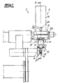
- the device 1 shown in the figures is used for mechanical finishing of raceways on rolling bearing rings for cylindrical roller bearings and tapered roller bearings.
- the device 1 is associated with a tool spindle 2 in which a workpiece 3 to be machined is tensioned and can be driven in rotation about the spindle axis 4 during finish machining.
- the basic structure of the device 1 includes a carrier 5, a carriage assembly 6, which has a carriage 7 and a slide guide 8 for linear guidance of the carriage 7, an eccentric 9 for generating oscillatory movements of the carriage 7, a tool carrier 10 fastened to the carriage 7 and a tool holder 10 connected to the stone holder 11 with a finishing stone 12.
- the tool carrier 10 has an adjusting device 13 for linear adjustment of the stone holder 11 transversely to the direction of movement of the carriage 7. During finish machining, the finishing stone 12 bears against the peripheral surface of the rotationally driven workpiece 3 with a predetermined pressure force.
- the finishing stone 12 executes oscillatory movements, wherein the oscillation path and the oscillation frequency are variable.
- the eccentric 9 an NC-controlled servo drive 14, z. an AC servomotor, on.
- the output shaft 15 of the servo drive 14 performs reversing rotational movements, wherein the pivot angle ⁇ is freely programmable.
- the reversing rotational movement is transmitted to the carriage 7 by an eccentric arrangement 16.
- the pivot angle ⁇ By adjusting the pivot angle ⁇ , the stroke of the carriage 7 is variable.
- the oscillation frequency of the oscillating movement performed by the finishing stone 12 is also controllable.
- the carriage guide 8 is arranged on a rotary plate 17, which is fastened to the output shaft 15 coaxial axis 18 rotatable on the carrier 5.
- the axis of rotation 4 of the workpiece and slide guide 8 are aligned parallel to each other ( Fig. 6a ).
- the rotary plate 17 is adjusted by an angle ⁇ , so that the carriage guide 8 is aligned parallel to the cone / conical surface to be machined ( Fig. 6b ).
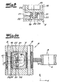
- a connecting piece 19 is connected, which has a shaft 20 of the output shaft 15 offset staggered pin 20 has.
- the pin 20 cooperates with slide surfaces 21 on the carriage 7, which transmit a acting in the direction of movement of the carriage 7 component of the pin movement on the carriage 7 and allow a pin movement transverse to the direction of movement of the carriage 7.
- two stop elements 22 are fixed, which are arranged on both sides of the pin 20 with a height offset opposite. They each have a planar sliding surface 21 which bears against a roller bearing 23, 23 'arranged on the journal.
- each rolling bearing On the pin 20, two rolling bearings 23, 23 'are arranged, each rolling bearing a stop element 22 is associated.
- a play-free motion transmission in the X direction is possible, while the rolling bearings roll in the transverse direction Y on the crank surfaces 21 and thereby permit a journal movement transversely to the direction of movement of the carriage.
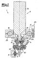
- the representations in the Fig. 1 and 2 If one deduces that the carrier 5 is fixed by means of a clamping device 24 to push rods 25 which are displaceable with a predetermined travel between two positions. In the working position shown in the figures, the finishing stone 12 bears against the workpiece 3 to be machined. In a second position, not shown, the finishing stone is spaced from the machined workpiece surface, so that a workpiece change is possible.
- the rotary plate 17, the carriage assembly 6 and the connector 19 for transmitting reversing movements of the output shaft 15 form a replaceable module.
- the tool carrier 10 can be connected directly or by means of an adapter to the output shaft 15 of the servo drive 14 and the device 1 can also be used for machining of spherical surfaces, in particular for machining bearing rings for ball bearings.
Landscapes
- Engineering & Computer Science (AREA)
- Mechanical Engineering (AREA)
- Grinding And Polishing Of Tertiary Curved Surfaces And Surfaces With Complex Shapes (AREA)
- Constituent Portions Of Griding Lathes, Driving, Sensing And Control (AREA)
Description
Die Erfindung betrifft eine Vorrichtung zur mechanischen Finishbearbeitung von Laufflächen an Wälzlagerringen, insbesondere zur Bearbeitung von Laufflächen an Zylinderrollen- und Kegelrollenlagem. Das Finishen ist ein zusätzlicher Bearbeitungsschritt zur Verbesserung der Rauhigkeit und Maßgenauigkeit von bearbeiteten Oberflächen. Beim Finishen erfolgt in der Regel ein Spanabtrag von wenigen Mikrometern. Bei der Finishbearbeitung wird das zu bearbeitende Werkstück rotierend angetrieben. Die Bearbeitung erfolgt mittels eines Finishsteins, der bei der Bearbeitung oszillierende Bewegungen ausführt. Der Oszillationsweg sowie die Oszillationsfrequenz haben Einfluss auf das Finishergebnis.The invention relates to a device for mechanical finishing of running surfaces of rolling bearing rings, in particular for the machining of running surfaces on cylindrical roller and tapered roller bearings. Finishing is an additional processing step to improve the roughness and dimensional accuracy of machined surfaces. Finishing usually involves a chip removal of a few micrometers. During finishing, the workpiece to be machined is driven in rotation. The processing takes place by means of a finishing stone, which performs oscillating movements during processing. The oscillation path and the oscillation frequency have an effect on the final result.
Eine Vorrichtung zur Finishbearbeitung von Wälzlagerringen ist aus
Der Erfindung liegt die Aufgabe zugrunde, eine Vorrichtung zur universellen Finishbearbeitung von Lagerringen für Zylinderrollen- und Kegelrollenlager anzugeben, die konstruktiv einfach aufgebaut ist und sich dadurch auszeichnet, dass die für eine Oszillationsbewegung eines Finishsteins zu bewegenden Massen klein sind. Der Oszillationsweg sowie die Oszillationsfrequenz, mit der der Finishstein über die zu bearbeitende Werkstückfläche bewegt wird, sollen variabel festlegbar sein.The invention has for its object to provide a device for universal finish machining of bearing rings for cylindrical roller and tapered roller bearings, which is structurally simple and is characterized in that the to be moved for an oscillatory movement of a finishing stone masses are small. The Oszillationsweg and the oscillation frequency with which the finishing stone is moved over the workpiece surface to be machined, should be variable fixable.
Gegenstand der Erfindung ist eine Vorrichtung nach Anspruch 1 zur mechanischen Finishbearbeitung von Laufflächen an Wälzlagerringen.The invention relates to a device according to
Ausgehend von einer Vorrichtung mit einem Träger, einer Schlittenanordnung, die einen Schlitten sowie eine Schlittenführung zur Linearführung des Schlittens aufweist, einem an dem Träger befestigten Exzenterantrieb zur Erzeugung von Oszillationsbewegungen des Schlittens, einem an dem Schlitten befestigten Werkzeugträger und einem an den Werkzeugträger angeschlossenen Steinhalter mit einem Finishstein wird die Aufgabe erfindungsgemäß dadurch gelöst, dass der Exzenterantrieb einen NC-gesteuerten Servoantrieb aufweist, dessen Abtriebswelle Reversierbewegungen mit frei programmierbarem Schwenkwinkel ausführt, dass die Schlittenführung an einer Drehplatte angeordnet ist, die um eine zur Abtriebswelle koaxiale Achse verdrehbar am Träger befestigt ist, und dass der Werkzeugträger eine Stelleinrichtung zur Linearverstellung des Steinhalters quer zur Bewegungsrichtung des Schlittens aufweist.Based on a device with a carrier, a carriage assembly having a carriage and a slide guide for linear guidance of the carriage, an eccentric drive attached to the carrier for generating oscillatory movements of the carriage, a tool carrier mounted on the carriage and a stone holder connected to the tool carrier a finishing stone, the object is achieved in that the eccentric drive has an NC-controlled servo drive, the output shaft reversing movements with freely programmable pivot angle executes that the carriage guide is disposed on a rotary plate which is rotatably mounted about a coaxial to the output shaft axis on the support, and that the tool carrier has an adjusting device for linear adjustment of the stone holder transversely to the direction of movement of the carriage.
Das zu bearbeitende Werkstück wird an einer Werkstückspindel gespannt und während der Finishbearbeitung in Rotation versetzt. Bei der Bearbeitung von Zylinderflächen sind die Spindelachse der Werkzeugspindel und die Bewegungsrichtung des Schlittens der erfindungsgemäßen Vorrichtung parallel ausgerichtet. Zur Bearbeitung von kegelförmigen Außenflächen oder konischen Innenflächen an Lagerringen für Kegelrollenlager wird durch Verstellung des Drehtellers die Ausrichtung der Schlittenführung retativ zur Rotationsachse des Werkstückes verändert und an den Winkel der zu bearbeitenden Werkstückfläche so angepasst, dass der Finishstein immer parallel zu der zu bearbeitenden Fläche bewegbar ist. Der Exzenterantrieb zur Erzeugung von Oszillationsbewegungen des Schlittens weist einen hochdynamischen Servoantrieb auf, der reversierende Drehbewegungen ausführt. Bevorzugt ist die Verwendung eines AC-Servomotors. Der Schwenkwinkel des Servoantriebs ist frei programmierbar. Da die Abtriebswelle des Servomotors durch eine Exzenteranordnung auf den Schlitten wirkt, ändert sich mit dem Schwenkwinkel ihrer Reversierbewegungen zugleich auch der Linearhub des Schlittens. Der Linearhub des Schlittens und der Schwenkwinkel der Abtriebswelle stehen in einem festen Verhältnis zueinander. Durch die Motordrehzahl des Servoantriebs ist ferner die Oszillationsfrequenz des Linearhubs veränderbar. Sowohl der Schwenkwinkel für die Reversierbewegungen der Abtriebswelle als auch die Motordrehzahl des Servoantriebs können während einer Finishbearbeitung laufend verändert werden, um das Finishen zu beeinflussen. Durch eine entsprechende Steuerung des Servomotors sind Oszillationsbewegungen mit kurzem Hub oder langem Hub sowie auch mit unterschiedlichen Frequenzen erzeugbar. Ferner können Oszillationsbewegungen mit langem Hub und Oszillationsbewegungen mit kurzem Hub überlagert werden.The workpiece to be machined is clamped to a workpiece spindle and set in rotation during finishing. When machining cylindrical surfaces, the spindle axis of the tool spindle and the direction of movement of the carriage of the device according to the invention are aligned in parallel. For machining conical outer surfaces or conical Inner surfaces of bearing rings for tapered roller bearings is changed by adjusting the turntable, the orientation of the carriage guide retative to the axis of rotation of the workpiece and adapted to the angle of the workpiece surface to be machined so that the finishing stone is always movable parallel to the surface to be machined. The eccentric drive for generating oscillatory movements of the carriage has a highly dynamic servo drive, which performs reversing rotational movements. Preferred is the use of an AC servo motor. The swivel angle of the servo drive is freely programmable. Since the output shaft of the servomotor acts by an eccentric on the slide, changes with the tilt angle of their reversing movements at the same time the linear stroke of the carriage. The linear stroke of the carriage and the pivot angle of the output shaft are in a fixed relationship to each other. By the motor speed of the servo drive, the oscillation frequency of the linear stroke is also variable. Both the swing angle for the reversing motions of the output shaft and the motor speed of the servo drive can be continuously changed during a finish machining to affect the finishing. By an appropriate control of the servo motor oscillatory movements with short stroke or long stroke and also with different frequencies can be generated. Furthermore, long stroke oscillatory motions and short stroke oscillatory motions may be superimposed.
Die Exzenteranordnung, die für die Bewegungsübertragung der Abtriebswelle auf den Schlitten der Schlittenanordnung notwendig ist, kann unterschiedlich konstruktiv ausgebildet sein. Gemäß einer bevorzugten Ausführung ist an die Abtriebswelle des Servoantriebs ein Anschlussstück angeschlossen, welches einen zur Wellenachse der Abtriebswelle versetzt angeordneten Zapfen aufweist. Der Zapfen wirkt mit Kulissenflächen an dem Schlitten zusammen, welche eine in Bewegungsrichtung des Schlittens wirkende Komponente der Zapfenbewegung auf den Schlitten übertragen und eine Zapfenbewegung quer zur Bewegungsrichtung des Schlittens zulassen. Um eine möglichst spielfreie Bewegungsübertragung zu realisieren, sind vorzugsweise an dem Schlitten zwei Anschlagelemente befestigt, die beidseits des Zapfens mit einem Höhenversatz gegenüberliegend angeordnet sind und eine ebene Kulissenfläche aufweist, die an jeweils einem auf dem Zapfen angeordneten Wälzlager anliegt. Auf dem Zapfen sind zwei Wälzlager hintereinander angeordnet, wobei jedem Wälzlager eines der Anschlagelemente zugeordnet ist. Es versteht sich, dass die Position der Anschlagelemente zwecks Spielbeseitigung einstell- bzw. justierbar ist.The eccentric, which is necessary for the transmission of movement of the output shaft to the carriage of the carriage assembly may be designed differently constructive. According to a preferred embodiment, a connecting piece is connected to the output shaft of the servo drive, which has a staggered to the shaft axis of the output shaft arranged pin. The pin cooperates with sliding surfaces on the carriage, which transmit a component of the pin movement acting in the direction of movement of the carriage onto the carriage and permit a pin movement transverse to the direction of movement of the carriage. In order to realize a backlash-free motion transmission, two stop elements are preferably attached to the carriage, which are arranged on both sides of the pin with a height offset opposite and having a planar gate surface, which rests against each one arranged on the pin bearings. On the pin two rolling bearings are arranged one behind the other, each roller bearing is associated with one of the stop elements. It is understood that the position of the stop elements for the purpose of clearance elimination is adjustable or adjustable.
Die erfindungsgemäße Vorrichtung ist modular aufgebaut und kann mit wenigen Handgriffen so umgerüstet werden, dass die Vorrichtung unter Nutzung des Servoantriebs auch zur Finishbearbeitung von Wälzlagerringen für Kugellager verwendet werden kann. Die Drehplatte, die Schlittenanordnung sowie das Anschlussstück zur Übertragung der Oszillationsbewegungen der Abtriebswelle bilden eine auswechselbare Baugruppe. Nach Ausbau dieser Baugruppe ist der Werkzeugträger unmittelbar oder mittels eines Adapters mittelbar an die Abtriebswelle des Servoantriebs anschließbar. Die reversierende Bewegungen des Motors übertragen sich als Schwenkbewegungen auf den Steinhalter, so dass die Vorrichtung auch zur Finishbearbeitung von sphärisch gekrümmten Flächen verwendet werden kann. Anwender, welche die erfindungsgemäße Vorrichtung zunächst zur Bearbeitung von Wälzlagerringen für Kugellager einsetzen wollen, können die Vorrichtung nachträglich durch Einbau der beschriebenen Baugruppe auch zur Bearbeitung von Zylinderrollenlagem und Kegelrollenlagern nutzen.The device according to the invention has a modular structure and can be retrofitted in a few steps so that the device can be used by using the servo drive for finish machining of roller bearing rings for ball bearings. The rotary plate, the carriage assembly and the connector for transmitting the oscillatory movements of the output shaft form a replaceable module. After removal of this module, the tool carrier is directly or indirectly connected by means of an adapter to the output shaft of the servo drive. The reversing movements of the motor are transmitted as pivotal movements on the stone holder, so that the device can also be used for finishing of spherically curved surfaces. Users who use the device according to the invention first for machining roller bearing rings for ball bearings want to use the device can subsequently by installing the assembly described also for processing Zylinderrollenlagem and tapered roller bearings use.
Die gesamte Vorrichtung kann an eine Stelleinrichtung, z. B. an einen Schlitten, angeschlossen werden, mit der die Vorrichtung zwischen einer Arbeitsposition und einer zweiten Position, in der der Finishstein von der Werkstückfläche beabstandet ist, bewegbar ist. Wenn die Vorrichtung die zweite Position einnimmt, ist ein problemloser Werkstückwechsel möglich. Vorzugsweise ist der Träger daher mittels einer Klemmeinrichtung an Schubstangen befestigt, die mit einem vorgegebenen Stellweg zwischen zwei Position verschiebbar sind.The entire device can be connected to an adjusting device, for. B. to a carriage, are connected, with which the device between a working position and a second position in which the finishing stone is spaced from the workpiece surface, is movable. If the device takes the second position, a trouble-free workpiece change is possible. Preferably, the carrier is therefore fastened by means of a clamping device to push rods, which are displaceable with a predetermined travel between two positions.
Im Folgenden wird die Erfindung anhand einer lediglich ein Ausführungsbeispiel darstellenden Zeichnung erläutert. Es zeigen schematisch
- Fig. 1
- die Längsansicht einer Vorrichtung zur Bearbeitung von Laufflächen an Lagerringen für Zylinderrollen- und Kegel- rollenlager,
- Fig.2
- den Schnitt A-A aus
Fig. 1 , - Fig. 3
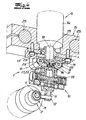
- eine perspektivische Darstellung der in
Fig. 1 dargestellten Vorrichtung, - Fig.4
- eine aufgeschnittene perspektivische Darstellung der Vorrichtung,
- Fig. 5
- ein Detail der in den Figuren dargestellten Vorrichtung im Schnitt,
- Fig. 6a und 6b
- die Bearbeitung von Lagerringen für ein Zylinderrollenlager und für ein Kegelrollenlager unter Verwendung der Vorrichtung.
- Fig. 1
- the longitudinal view of a device for machining running surfaces on bearing rings for cylindrical roller and tapered roller bearings,
- Fig.2
- the cut AA
Fig. 1 . - Fig. 3
- a perspective view of in
Fig. 1 illustrated device, - Figure 4
- a cutaway perspective view of the device,
- Fig. 5
- a detail of the device shown in the figures in section,
- Fig. 6a and 6b
- the machining of bearing rings for a cylindrical roller bearing and a tapered roller bearing using the device.
Die in den Figuren dargestellte Vorrichtung 1 dient zur mechanischen Finishbearbeitung von Laufflächen an Wälzlagerringen für Zylinderrollenlager und Kegelrollenlager. Die Vorrichtung 1 ist einer Werkzeugspindel 2 zugeordnet, in der ein zu bearbeitendes Werkstück 3 gespannt ist und während der Finishbearbeitung rotierend um die Spindelachse 4 antreibbar ist. Zum grundsätzlichen Aufbau der Vorrichtung 1 gehören ein Träger 5, eine Schlittenanordnung 6, die einen Schlitten 7 sowie eine Schlittenführung 8 zur Linearführung des Schlittens 7 aufweist, ein Exzenterantrieb 9 zur Erzeugung von Oszillationsbewegungen des Schlittens 7, ein an dem Schlitten 7 befestigter Werkzeugträger 10 sowie ein an den Werkzeugträger angeschlossener Steinhalter 11 mit einem Finishstein 12. Der Werkzeugträger 10 weist eine Stelleinrichtung 13 zur Linearverstellung des Steinhalters 11 quer zur Bewegungsrichtung des Schlittens 7 auf. Während der Finishbearbeitung liegt der Finishstein 12 mit einer vorgegebenen Andruckkraft an der zu bearbeitenden Umfangsfläche des rotierend angetriebenen Werkstücks 3 an.The
Bei der Finishbearbeitung führt der Finishstein 12 Oszillationsbewegungen aus, wobei der Oszillationsweg sowie die Oszillationsfrequenz veränderbar sind. Dazu weist der Exzenterantrieb 9 einen NC-gesteuerten Servoantrieb 14, z. einen AC-Servomotor, auf. Die Abtriebswelle 15 des Servoantriebs 14 führt reversierende Drehbewegungen aus, wobei der Schwenkwinkel α frei programmierbar ist. Die reversierende Drehbewegung wird durch eine Exzenteranordnung 16 auf den Schlitten 7 übertragen. Durch Verstellung des Schwenkwinkels α ist der Hub des Schlittens 7 veränderbar. Durch die Motordrehzahl des Servoantriebs 14 ist ferner die Oszillationsfrequenz der von dem Finishstein 12 ausgeführten Oszillationsbewegung steuerbar.During finish machining, the finishing
Die Schlittenführung 8 ist an einer Drehplatte 17 angeordnet, die um eine zur Abtriebswelle 15 koaxiale Achse 18 verdrehbar an dem Träger 5 befestigt ist. Zur Bearbeitung von Lagerringen für Zylinderrollenlager sind die Rotationsachse 4 des Werkstückes und Schlittenführung 8 parallel zueinander ausgerichtet (
Die in
Insbesondere den Darstellungen in den
Die Drehplatte 17, die Schlittenanordnung 6 sowie das Anschlussstück 19 zur Übertragung von Reversierbewegungen der Abtriebswelle 15 bilden eine auswechselbare Baugruppe. Nach Ausbau dieser Baugruppe ist der Werkzeugträger 10 unmittelbar oder mittels eines Adapters an die Abtriebswelle 15 des Servoantriebs 14 anschließbar und kann die Vorrichtung 1 auch zur Bearbeitung von sphärischen Flächen, insbesondere zur Bearbeitung von Lagerringen für Kugellager, genutzt werden.The
Claims (5)
- Apparatus for mechanically finishing running faces of roller bearing surfaces with
a support (5),
a slide arrangement (6), which has a slide (7) as well as a slide guide (8) for guiding the slide in a linear manner,
an eccentric drive (9) fastened to the support (5) for generating oscillatory movements of the slide (7),
a tool support (10) fastened to the slide (7) and
a stone holder (11) attached to the tool support (10), with a finishing stone (12),
characterised in that the eccentric drive (9) has an NC-controlled servo drive, the output shaft (15) of which executes reversing movements with a freely programmable pivot angle (α), that the slide guide (8) is arranged on a turning plate (17) which is fastened to the support (5) such that it can rotate about an axis (18) coaxial to the output shaft, and that the tool support (10) has an adjustment device (13) for linearly adjusting the stone holder (11) transversely to the direction of movement of the slide (7). - Apparatus according to Claim 1, characterised in that a connecting piece (19) is attached to the output shaft (15) of the servo drive (14), which connecting piece has a pin (20) which is arranged offset to the shaft axis of the output shaft (15), and that the pin (20) interacts with link faces (21) on the slide (7) which transmit a component of the pin movement which acts in the direction of movement of the slide (7) to the slide and allow a pin movement transversely to the direction of movement of the slide (7).
- Apparatus according to Claim 2, characterised in that two roller bearings (23, 23') are arranged on the pin (20) and that two stop elements (22) are fastened to the slide (7), which are arranged opposite with an offset in height on both sides of the pin (20) and have a flat link face (21), which each bear against one of the two roller bearings (23, 23').
- Apparatus according to Claim 2 or 3, characterised in that the turning plate (17), the slide arrangement (6) and the connecting piece (19) for transmitting the oscillatory movement of the output shaft (15) form a replaceable assembly and that the tool support (10) can be attached to the output shaft (15) of the servo drive (14) directly or by means of an adapter.
- Apparatus according to one of Claims 1 to 4, characterised in that the support (5) is fastened by means of a clamping device (24) to pushing rods (25) which can be displaced between two positions with a predefined travel.
Applications Claiming Priority (1)
| Application Number | Priority Date | Filing Date | Title |
|---|---|---|---|
| DE200810011215 DE102008011215B4 (en) | 2008-02-26 | 2008-02-26 | Device for the mechanical finishing of running surfaces on roller bearing rings |
Publications (2)
| Publication Number | Publication Date |
|---|---|
| EP2095906A1 EP2095906A1 (en) | 2009-09-02 |
| EP2095906B1 true EP2095906B1 (en) | 2010-12-29 |
Family
ID=40749132
Family Applications (1)
| Application Number | Title | Priority Date | Filing Date |
|---|---|---|---|
| EP20090000410 Not-in-force EP2095906B1 (en) | 2008-02-26 | 2009-01-14 | Device for mechanically finishing baring surfaces of bearings |
Country Status (2)
| Country | Link |
|---|---|
| EP (1) | EP2095906B1 (en) |
| DE (2) | DE102008011215B4 (en) |
Families Citing this family (3)
| Publication number | Priority date | Publication date | Assignee | Title |
|---|---|---|---|---|
| CN105437023A (en) * | 2015-12-31 | 2016-03-30 | 无锡诚石轴承有限公司 | Multi-channel mandrel machining equipment |
| CN112917375B (en) * | 2021-03-23 | 2022-06-10 | 中国航发哈尔滨轴承有限公司 | Oilstone swing mechanism for lapping bearing ring |
| CN114378686A (en) * | 2022-02-08 | 2022-04-22 | 浙江诚本轴承滚子有限公司 | Superfinishing method and superfinishing machine for bearing roller |
Family Cites Families (5)
| Publication number | Priority date | Publication date | Assignee | Title |
|---|---|---|---|---|
| DE2413000A1 (en) * | 1974-03-18 | 1975-09-25 | Supfina Maschf Hentzen | PROCESS FOR FINE MACHINING OF CYLINDRICAL OR CONICAL SURFACES |
| DE19804885C5 (en) * | 1998-02-09 | 2004-07-15 | Supfina Grieshaber Gmbh & Co. Kg | Superfinishing device |
| JP4389554B2 (en) * | 2002-12-19 | 2009-12-24 | 日本精工株式会社 | Super finishing equipment |
| JP2006255889A (en) * | 2006-05-29 | 2006-09-28 | Jtekt Corp | Super finishing device |
| DE202007007704U1 (en) * | 2007-05-31 | 2007-09-06 | Thielenhaus Technologies Gmbh | Device for mechanical finishing of roller bearing rings has computer controller for controlling pivot angle and alignment of bisector of pivot angle |
-
2008
- 2008-02-26 DE DE200810011215 patent/DE102008011215B4/en not_active Expired - Fee Related
-
2009
- 2009-01-14 DE DE200950000245 patent/DE502009000245D1/en active Active
- 2009-01-14 EP EP20090000410 patent/EP2095906B1/en not_active Not-in-force
Also Published As
| Publication number | Publication date |
|---|---|
| DE102008011215A1 (en) | 2009-09-03 |
| EP2095906A1 (en) | 2009-09-02 |
| DE102008011215B4 (en) | 2010-04-08 |
| DE502009000245D1 (en) | 2011-02-10 |
Similar Documents
| Publication | Publication Date | Title |
|---|---|---|
| EP2688710B1 (en) | Grinding machine device with pivotable mounting of a grinding spindle unit and method for pivoting a grinding spindle unit on a grinding machine | |
| DE68901850T2 (en) | FOR THE GRINDING OF CYLINDRICAL BEARING SURFACES OF WORKPIECES, ESPECIALLY FOR THE MACHINING OF CRANKSHAFT AND CRANK PINS BY MEANS OF A BELT SANDER. | |
| DE102007054897B4 (en) | Device for mechanical finish machining of spherical surfaces on rotationally symmetrical workpieces | |
| DE102008046451B4 (en) | Device for mechanical finishing of peripheral surfaces of rotationally symmetrical workpieces, in particular rolling bearing rings | |
| EP2338640A1 (en) | Machine for grinding optical workpieces, in particular plastic eyeglass lenses | |
| EP1990133B1 (en) | Grinder as tool for a processing device | |
| DE102006058710A1 (en) | Machine tool for processing crank webs radius transition on rod- and main bearings of crankshafts for internal combustion engine, has a processing device, which is led by two orthogonal computer numerical control machine axes | |
| DE102009006797A1 (en) | Lens processing device, has actuator mechanisms causing spindles for accomplishing linear forward and backward movement in X-axis direction perpendicular to Y-axis and Z-axis, where Y-axis is perpendicular to plane | |
| WO2015021565A1 (en) | Machine for machining workpieces | |
| DE3225977A1 (en) | METHOD AND DEVICE FOR FINELY FINISHING CONVEX OR CONCAVE COVERING SURFACES OF ROTATION-SYMMETRICAL WORKPIECES, IN PARTICULAR OF ROLLER BEARING REELS | |
| DE102011089654B4 (en) | METHOD FOR ROTATING WORKING TOOLS ON THE CRANKSHAFT OF A CRANKSHAFT, USING THE METHOD FOR COMPLETELY WORKING CRANKSHAFT ROLLERS, AND CRANKSHAFT ROTATING MACHINE FOR ROTATING THE PLANE SHOULDERS | |
| EP1068917A2 (en) | Device and method for machining crankpins | |
| EP2095906B1 (en) | Device for mechanically finishing baring surfaces of bearings | |
| DE10030087B4 (en) | Method and device for measuring and processing workpieces | |
| DE2733070A1 (en) | GRINDING MACHINE | |
| DE102007021659A1 (en) | Surface grinding method for producing flat work piece surface in surface grinding machine, involves producing eccentric rotary motion of grinding spindle about grinding unit axis that is arranged in eccentric distance to spindle axis | |
| DE102006036004A1 (en) | Metallic or ceramic workpiece surface processing e.g. grinding process, device, has tool spindle supported at radial bearings and axial bearing, where bearings are designed as adjustable magnetic bearing with adjustable bearing slots | |
| DE202007007704U1 (en) | Device for mechanical finishing of roller bearing rings has computer controller for controlling pivot angle and alignment of bisector of pivot angle | |
| DE102011078735B4 (en) | finish device | |
| DE102014102282B4 (en) | Finish tool carrier and finishing unit | |
| DE2807268C3 (en) | Machine for centering optical lenses | |
| DE102008023081A1 (en) | Sharpening device for workpiece i.e. cutter of lawn mower or chopper, has stationary sharpening wheel, swiveling device swivelably supported on base frame around vertical axle, and bolt swivelably supported on bearing block | |
| DE102014106746A1 (en) | Device for mechanical finishing of peripheral surfaces on workpieces | |
| EP0867251B1 (en) | Device for setting the exact position of a saw blade on the running surface of the wheels of band saw | |
| DE102016014515A1 (en) | Apparatus for rotary finishing of workpiece surfaces |
Legal Events
| Date | Code | Title | Description |
|---|---|---|---|
| PUAI | Public reference made under article 153(3) epc to a published international application that has entered the european phase |
Free format text: ORIGINAL CODE: 0009012 |
|
| AK | Designated contracting states |
Kind code of ref document: A1 Designated state(s): AT BE BG CH CY CZ DE DK EE ES FI FR GB GR HR HU IE IS IT LI LT LU LV MC MK MT NL NO PL PT RO SE SI SK TR |
|
| AX | Request for extension of the european patent |
Extension state: AL BA RS |
|
| 17P | Request for examination filed |
Effective date: 20090811 |
|
| 17Q | First examination report despatched |
Effective date: 20091007 |
|
| AKX | Designation fees paid |
Designated state(s): DE FR GB IT |
|
| GRAP | Despatch of communication of intention to grant a patent |
Free format text: ORIGINAL CODE: EPIDOSNIGR1 |
|
| GRAC | Information related to communication of intention to grant a patent modified |
Free format text: ORIGINAL CODE: EPIDOSCIGR1 |
|
| GRAS | Grant fee paid |
Free format text: ORIGINAL CODE: EPIDOSNIGR3 |
|
| GRAA | (expected) grant |
Free format text: ORIGINAL CODE: 0009210 |
|
| AK | Designated contracting states |
Kind code of ref document: B1 Designated state(s): DE FR GB IT |
|
| REG | Reference to a national code |
Ref country code: GB Ref legal event code: FG4D Free format text: NOT ENGLISH |
|
| REF | Corresponds to: |
Ref document number: 502009000245 Country of ref document: DE Date of ref document: 20110210 Kind code of ref document: P |
|
| REG | Reference to a national code |
Ref country code: DE Ref legal event code: R096 Ref document number: 502009000245 Country of ref document: DE Effective date: 20110210 |
|
| PGFP | Annual fee paid to national office [announced via postgrant information from national office to epo] |
Ref country code: FR Payment date: 20110202 Year of fee payment: 3 Ref country code: DE Payment date: 20110124 Year of fee payment: 3 |
|
| PLBE | No opposition filed within time limit |
Free format text: ORIGINAL CODE: 0009261 |
|
| STAA | Information on the status of an ep patent application or granted ep patent |
Free format text: STATUS: NO OPPOSITION FILED WITHIN TIME LIMIT |
|
| 26N | No opposition filed |
Effective date: 20110930 |
|
| REG | Reference to a national code |
Ref country code: DE Ref legal event code: R097 Ref document number: 502009000245 Country of ref document: DE Effective date: 20110930 |
|
| PGFP | Annual fee paid to national office [announced via postgrant information from national office to epo] |
Ref country code: IT Payment date: 20120131 Year of fee payment: 4 |
|
| REG | Reference to a national code |
Ref country code: FR Ref legal event code: ST Effective date: 20120928 |
|
| PG25 | Lapsed in a contracting state [announced via postgrant information from national office to epo] |
Ref country code: DE Free format text: LAPSE BECAUSE OF NON-PAYMENT OF DUE FEES Effective date: 20120801 |
|
| REG | Reference to a national code |
Ref country code: DE Ref legal event code: R119 Ref document number: 502009000245 Country of ref document: DE Effective date: 20120801 |
|
| PG25 | Lapsed in a contracting state [announced via postgrant information from national office to epo] |
Ref country code: FR Free format text: LAPSE BECAUSE OF NON-PAYMENT OF DUE FEES Effective date: 20120131 |
|
| GBPC | Gb: european patent ceased through non-payment of renewal fee |
Effective date: 20130114 |
|
| PG25 | Lapsed in a contracting state [announced via postgrant information from national office to epo] |
Ref country code: GB Free format text: LAPSE BECAUSE OF NON-PAYMENT OF DUE FEES Effective date: 20130114 |
|
| PG25 | Lapsed in a contracting state [announced via postgrant information from national office to epo] |
Ref country code: IT Free format text: LAPSE BECAUSE OF NON-PAYMENT OF DUE FEES Effective date: 20130114 |