EP2095801B1 - Method and apparatus to form a spherical end of an elongated cylindrical tube, in particular of a tampon applicator - Google Patents
Method and apparatus to form a spherical end of an elongated cylindrical tube, in particular of a tampon applicator Download PDFInfo
- Publication number
- EP2095801B1 EP2095801B1 EP09250601A EP09250601A EP2095801B1 EP 2095801 B1 EP2095801 B1 EP 2095801B1 EP 09250601 A EP09250601 A EP 09250601A EP 09250601 A EP09250601 A EP 09250601A EP 2095801 B1 EP2095801 B1 EP 2095801B1
- Authority
- EP
- European Patent Office
- Prior art keywords
- forming element
- tampon applicator
- tampon
- fluid
- forming
- Prior art date
- Legal status (The legal status is an assumption and is not a legal conclusion. Google has not performed a legal analysis and makes no representation as to the accuracy of the status listed.)
- Not-in-force
Links
- 238000000034 method Methods 0.000 title claims description 38
- 239000012530 fluid Substances 0.000 claims description 49
- 238000010438 heat treatment Methods 0.000 claims description 42
- 239000000463 material Substances 0.000 claims description 29
- 239000012809 cooling fluid Substances 0.000 claims description 27
- 238000001816 cooling Methods 0.000 claims description 25
- 238000007493 shaping process Methods 0.000 claims description 7
- 239000004698 Polyethylene Substances 0.000 claims description 3
- -1 polyethylene Polymers 0.000 claims description 3
- 229920000573 polyethylene Polymers 0.000 claims description 3
- 238000003780 insertion Methods 0.000 description 52
- 230000037431 insertion Effects 0.000 description 52
- 206010021639 Incontinence Diseases 0.000 description 5
- 206010052428 Wound Diseases 0.000 description 5
- 208000027418 Wounds and injury Diseases 0.000 description 5
- 230000002745 absorbent Effects 0.000 description 5
- 239000002250 absorbent Substances 0.000 description 5
- 210000001215 vagina Anatomy 0.000 description 5
- 239000002699 waste material Substances 0.000 description 4
- 239000000853 adhesive Substances 0.000 description 3
- 230000001070 adhesive effect Effects 0.000 description 3
- 239000011111 cardboard Substances 0.000 description 3
- 238000000576 coating method Methods 0.000 description 3
- 238000011109 contamination Methods 0.000 description 3
- 239000011087 paperboard Substances 0.000 description 3
- 239000004033 plastic Substances 0.000 description 3
- 229920003023 plastic Polymers 0.000 description 3
- 238000011282 treatment Methods 0.000 description 3
- 239000011248 coating agent Substances 0.000 description 2
- 239000003814 drug Substances 0.000 description 2
- 238000001746 injection moulding Methods 0.000 description 2
- 238000004519 manufacturing process Methods 0.000 description 2
- 239000002985 plastic film Substances 0.000 description 2
- 238000012545 processing Methods 0.000 description 2
- 239000000126 substance Substances 0.000 description 2
- 238000012546 transfer Methods 0.000 description 2
- XLYOFNOQVPJJNP-UHFFFAOYSA-N water Substances O XLYOFNOQVPJJNP-UHFFFAOYSA-N 0.000 description 2
- 229920000298 Cellophane Polymers 0.000 description 1
- 206010046543 Urinary incontinence Diseases 0.000 description 1
- 238000005299 abrasion Methods 0.000 description 1
- 238000010521 absorption reaction Methods 0.000 description 1
- 239000011149 active material Substances 0.000 description 1
- 238000013019 agitation Methods 0.000 description 1
- WYTGDNHDOZPMIW-RCBQFDQVSA-N alstonine Natural products C1=CC2=C3C=CC=CC3=NC2=C2N1C[C@H]1[C@H](C)OC=C(C(=O)OC)[C@H]1C2 WYTGDNHDOZPMIW-RCBQFDQVSA-N 0.000 description 1
- 229920000704 biodegradable plastic Polymers 0.000 description 1
- 238000000071 blow moulding Methods 0.000 description 1
- 210000001124 body fluid Anatomy 0.000 description 1
- 239000004927 clay Substances 0.000 description 1
- 238000013461 design Methods 0.000 description 1
- 238000010586 diagram Methods 0.000 description 1
- 201000010099 disease Diseases 0.000 description 1
- 208000037265 diseases, disorders, signs and symptoms Diseases 0.000 description 1
- 210000000613 ear canal Anatomy 0.000 description 1
- 230000007613 environmental effect Effects 0.000 description 1
- 239000000835 fiber Substances 0.000 description 1
- 229920002457 flexible plastic Polymers 0.000 description 1
- 238000011010 flushing procedure Methods 0.000 description 1
- 239000003292 glue Substances 0.000 description 1
- 238000007654 immersion Methods 0.000 description 1
- 230000003993 interaction Effects 0.000 description 1
- 229920001684 low density polyethylene Polymers 0.000 description 1
- 239000004702 low-density polyethylene Substances 0.000 description 1
- 239000000314 lubricant Substances 0.000 description 1
- 230000002175 menstrual effect Effects 0.000 description 1
- 239000010445 mica Substances 0.000 description 1
- 229910052618 mica group Inorganic materials 0.000 description 1
- 238000002156 mixing Methods 0.000 description 1
- 239000000123 paper Substances 0.000 description 1
- 229920006255 plastic film Polymers 0.000 description 1
- 238000011321 prophylaxis Methods 0.000 description 1
- 230000000717 retained effect Effects 0.000 description 1
- 238000002791 soaking Methods 0.000 description 1
- 229920001169 thermoplastic Polymers 0.000 description 1
- 229920001187 thermosetting polymer Polymers 0.000 description 1
- 239000004416 thermosoftening plastic Substances 0.000 description 1
- 230000000007 visual effect Effects 0.000 description 1
- 230000029663 wound healing Effects 0.000 description 1
Images


Classifications
-
- B—PERFORMING OPERATIONS; TRANSPORTING
- B29—WORKING OF PLASTICS; WORKING OF SUBSTANCES IN A PLASTIC STATE IN GENERAL
- B29C—SHAPING OR JOINING OF PLASTICS; SHAPING OF MATERIAL IN A PLASTIC STATE, NOT OTHERWISE PROVIDED FOR; AFTER-TREATMENT OF THE SHAPED PRODUCTS, e.g. REPAIRING
- B29C57/00—Shaping of tube ends, e.g. flanging, belling or closing; Apparatus therefor, e.g. collapsible mandrels
- B29C57/10—Closing
-
- A—HUMAN NECESSITIES
- A61—MEDICAL OR VETERINARY SCIENCE; HYGIENE
- A61F—FILTERS IMPLANTABLE INTO BLOOD VESSELS; PROSTHESES; DEVICES PROVIDING PATENCY TO, OR PREVENTING COLLAPSING OF, TUBULAR STRUCTURES OF THE BODY, e.g. STENTS; ORTHOPAEDIC, NURSING OR CONTRACEPTIVE DEVICES; FOMENTATION; TREATMENT OR PROTECTION OF EYES OR EARS; BANDAGES, DRESSINGS OR ABSORBENT PADS; FIRST-AID KITS
- A61F13/00—Bandages or dressings; Absorbent pads
- A61F13/15—Absorbent pads, e.g. sanitary towels, swabs or tampons for external or internal application to the body; Supporting or fastening means therefor; Tampon applicators
- A61F13/20—Tampons, e.g. catamenial tampons; Accessories therefor
- A61F13/2082—Apparatus or processes of manufacturing
-
- A—HUMAN NECESSITIES
- A61—MEDICAL OR VETERINARY SCIENCE; HYGIENE
- A61F—FILTERS IMPLANTABLE INTO BLOOD VESSELS; PROSTHESES; DEVICES PROVIDING PATENCY TO, OR PREVENTING COLLAPSING OF, TUBULAR STRUCTURES OF THE BODY, e.g. STENTS; ORTHOPAEDIC, NURSING OR CONTRACEPTIVE DEVICES; FOMENTATION; TREATMENT OR PROTECTION OF EYES OR EARS; BANDAGES, DRESSINGS OR ABSORBENT PADS; FIRST-AID KITS
- A61F13/00—Bandages or dressings; Absorbent pads
- A61F13/15—Absorbent pads, e.g. sanitary towels, swabs or tampons for external or internal application to the body; Supporting or fastening means therefor; Tampon applicators
- A61F13/20—Tampons, e.g. catamenial tampons; Accessories therefor
- A61F13/26—Means for inserting tampons, i.e. applicators
-
- B—PERFORMING OPERATIONS; TRANSPORTING
- B29—WORKING OF PLASTICS; WORKING OF SUBSTANCES IN A PLASTIC STATE IN GENERAL
- B29K—INDEXING SCHEME ASSOCIATED WITH SUBCLASSES B29B, B29C OR B29D, RELATING TO MOULDING MATERIALS OR TO MATERIALS FOR MOULDS, REINFORCEMENTS, FILLERS OR PREFORMED PARTS, e.g. INSERTS
- B29K2995/00—Properties of moulding materials, reinforcements, fillers, preformed parts or moulds
- B29K2995/0037—Other properties
- B29K2995/0059—Degradable
- B29K2995/006—Bio-degradable, e.g. bioabsorbable, bioresorbable or bioerodible
Definitions
- This invention relates generally to a method and apparatus for forming elongated cylindrical tubes useful for inserting substances into a mammalian body and more particularly relates to a method and apparatus of forming a portion of a tampon applicator.
- Insertion devices including tampon and nasal applicators, are generally known to be elongated cylindrical tubular structures that are used to house objects intended to be inserted in a body cavity and to expel the objects into the intended orifice.
- Applicators generally comprise an insertion member and a plunger.
- the object to be expelled from the applicator, such as a tampon, is positioned within the insertion member.
- the insertion member has a first end for insertion of the tampon and a second end for receipt of the plunger.
- the plunger is slightly smaller in diameter and is slidably positioned behind the tampon carried in the tampon applicator.
- the user will position the first end appropriately, grasp the insertion member, and push the plunger into the insertion member towards the first end to insert the tampon.
- a variety of applicators have employed visual marks to determine when the contents of the applicator have been fully expelled.
- Tampon applicators may be made from various materials including paperboard or plastic. Each type of material may have challenges during manufacture and use.
- a tampon insertion member will generally incorporate surface features at the rear or gripper end to allow the user to hold the applicator more or less securely while ejecting the tampon from the opposite end of the applicator.
- Another way to aid insertion of the applicator into the body and also protect the contained tampon is to "dome" the insertion end of the applicator.
- a domed end provides for a smooth insertion and may help prevent contamination of the tampon prior to use.
- GB 1484912 discusses a tampon inserter comprises a barrel portion with insertion end, cylindrical finger grip and plunger, the insertion end including a multiplicity of mangular segments which converge towards each other to form a dome and have a thickness less than that of the barrel portion so that they are flexible enough to allow the passage of tampon therethrough.
- the reduction in thickness between the barrel portion and the segments may be achieved either by injection moulding of thermoplastics or thermosetting plastic, or by use of laminated cardboard omitting some laminate layers at the insertion end.
- the forming element has a high thermal conductivity and a low thermal mass.
- the step of heating the forming element forming surface includes heating it to a temperature greater than the softening point of the heat-deformable material of the applicator portion.
- the step of cooling the forming element forming surface includes cooling it to a temperature less than the softening point of the heat-deformable material.
- the time required to heat and form the portion of the tampon applicator is less than about 90 seconds.
- the invention further provides an apparatus for shaping a tampon applicator comprising a mold body and means to provide at least a portion of the tampon applicator to the mold.
- the tampon applicator is at least partially formed of a heat-deformable material.
- the mold body has a forming element, a forming element fluid cavity, means to apply heat to the forming element, and means to provide cooling fluid through the forming element fluid cavity.
- the forming element has a high thermal conductivity and a low thermal mass and a forming surface.
- the forming element fluid cavity is adjacent to and in thermal contact with the forming element.
- the term "tampon,” refers to any type of absorbent structure that is inserted into the vaginal canal or other body cavities for the absorption of fluid therefrom, to aid in wound healing, or for the delivery of active materials, such as medicaments, or moisture.
- the tampon may be compressed into a generally cylindrical configuration in the radial direction, axially along the longitudinal axis or in both the radial and axial directions. While the tampon may be compressed into a substantially cylindrical configuration, other shapes are possible. These may include shapes having a cross section that may be described as rectangular, triangular, trapezoidal, semi-circular, hourglass, serpentine, or other suitable shapes.
- Tampons have an insertion end, withdrawal end, a length, a width, a longitudinal axis, a radial axis, and an outer surface.
- the tampon's length can be measured from the insertion end to the withdrawal end along the longitudinal axis.
- a typical compressed tampon for human use is 35-60 mm in length.
- a tampon may be straight or non-linear in shape, such as curved along the longitudinal axis.
- a typical compressed tampon is about 5 to about 20 mm wide.
- the width of a tampon unless otherwise stated in the specification, corresponds to the distance across the largest cross-section perpendicular to the length of the tampon.
- the tampons of the present invention also include nasal tampons.
- the tampon applicator of the present invention could be used to deliver any other type of absorbent or nonabsorbent object to any suitable cavity.
- the tampon applicator of the present invention could be used to insert a treatment ovule or an incontinence device.
- An "incontinence device,” as used herein refers to devices specifically designed, configured, and/or adapted for placement into a vagina in order to reduce the occurrence and/or severity of female urinary incontinence. While incontinence devices are typically made of non-absorbent materials, at least partially absorbent materials may also be used.
- incontinence devices are readily distinguishable from tampons.
- Non-limiting specific examples of such include any known hygienically designed applicators that are capable of receiving a tampon may be used for insertion of a tampon, including the so-called telescoping, tube and plunger, and the compact applicators, an applicator for providing medicament to an area for prophylaxis or treatment of disease, a spectroscope containing a microcamera in the tip connected via fiber optics, a speculum of any design, a tongue depressor, a tube for examining the ear canal, a nano-hollow pipe for guiding surgical instruments, and the like.
- expelled as used herein is meant the tampon is forced out of the insertion portion of the tampon applicator.
- Figs. 1 and 2 show embodiments of the tampon applicator of the present invention.
- the present invention is not limited to a structure having the particular configurations shown in the drawings or discussed herein.
- the tampon applicator of the present invention can have any configuration or size as long as the ease of delivery of the tampon into the body is retained.
- the tampon applicator 10 has a pre-expelled state as shown in Figs. 1 and 2 .
- applicator 10 has an insertion member 12 and a plunger 14.
- Insertion member 12 is hollow and has a first or insertion end 16 dimensioned for insertion into the body cavity (specifically the vaginal cavity of a female user), a second end 18 positioned oppositely to the first end 16 and a gripping portion 20.
- the first end 16 further has a plurality of petals 22.
- the insertion member 12 is sized and configured to house an insertable element, such as an absorbent tampon 24 having a withdrawal string 26.
- the insertion member 12 preferably has a substantially smooth exterior surface or exterior surface that exerts low drag with vaginal body tissue that will facilitate insertion of the insertion member 12 into a woman's vagina.
- the insertion member 12 can be coated to give it a high slip characteristic. Wax, polyethylene, a combination of wax and polyethylene, cellophane, clay, mica and other lubricants are representative coatings that can be applied to the insertion member 12 to facilitate comfortable insertion.
- the applicator 10 of the present invention can have geometries or cross-sections that are useful to contain the object to be inserted.
- the shape of the tampon 24 contained suggests the shape of the insertion member 12, but departures from this general rule can be made such that a cylindrical tampon 24 can be housed in a rectangular shaped applicator, for example.
- the insertion member 12 and plunger 14 can take on numerous cross-sectional shapes including without limitations, circular, oval, polygonal (e.g. trapezoidal, rectangular, triangular) and the like.
- the insertion member 12 and plunger 14 can be substantially elongated, such as in a linear fashion, curved or flexible, or it can take on other shapes that are apparent to one of ordinary skill in the art.
- the insertion member 12 and plunger 14 can be substantially elongated, curved or flexible, or it can take on other shapes that are apparent to one of ordinary skill in the art. Some examples of applicator shapes are described in WO 2004/024193 published by Lecan, et al. on Mar. 25, 2004 , and European Patent Application No, 1101473 published by Mitsuhiro, et al on May 23, 2001 .
- the insertion end 16 of the insertion member 12 can be substantially closed and can comprise petals, corrugations, or pleats. During insertion, when the tampon 24 is pushed upward by the plunger 14, the petals 22 open and to let the tampon 24 through, into the vagina.
- the applicator devices of the present invention include heat-deformable materials and may also include other materials generally known to those of ordinary skill in the art.
- the insertion member 12 and plunger 14 can be formed of plastic, e.g., by injection molding, blow-molding, extruding, or otherwise formed from flexible plastic, such as thermoformed from plastic sheet or folded or wound from plastic film.
- the applicator device may be made from biodegradable plastics such as those disclosed in Dabi et al., U. S. Pat. No. 5,910,520 .
- the sleeves may also include a paper or cardboard laminate in a manner known to those skilled in the art.
- the different tampon applicator parts can be constructed from different materials and processes.
- the tampon applicator 10 or any part of the tampon applicator can be formed of a spirally wound, convolutedly wound, or longitudinally seamed hollow tube that is formed from paper, paperboard, cardboard, or any combinations thereof.
- a coating may be provided to the surface.
- the tampon applicator 10 or any part of the tampon applicator can be constructed from a single ply of material or be formed from two or more plies that are bonded together to form a laminate. However, at least one ply of the laminate must comprise (including via coating) a heat-deformable material.
- the use of two or more plies or layers is preferred for it enables the manufacturer to use certain materials in the various layers that can enhance the performance of the tampon applicator or any part of the tampon applicator. When two or more plies are utilized, all the plies can be spirally wound, convolutedly wound, or longitudinally seamed to form an elongated cylinder.
- the tampon applicator or any part of the tampon applicator can be constructed using a smooth thin ply of material on the outside or exterior surface that surrounds a coarser and possibly thicker ply.
- the plies forming the tampon applicator or any part of the tampon applicator can be held together by an adhesive, such as glue, heat, pressure, ultrasonic, or any combinations thereof.
- the adhesive can be either water-soluble or water-insoluble.
- a water-soluble adhesive is preferred for environmental reasons in that the tampon applicator or any part of the tampon applicator will quickly break apart when it is immersed in water. Such immersion will occur should the tampon applicator or any part of the tampon applicator be disposed of by flushing it down a toilet.
- Typical dimensions for the tubular elements useful in tampon applicators include a length of about 5 to 8 cm, a diameter of about 8 to about 20 mm, and thicknesses of about 0.1 to 0.6 mm.
- the diameter of the plunger 14 is less than the diameter of the insertion member 12 to allow for a telescopic arrangement as shown in Figs. 1 and 2 .
- Fig. 3 shows the basics of a conventional two-step process (prior art).
- the insertion member and the plunger can be supplied from different sources but may be assembled prior to doming.
- a tampon may be contained within the assembly.
- the first end 50 of insertion member 52 is open and provided with petals 54.
- the open first end 50 of the insertion member 52 is aligned and placed within the heating chamber 56 of a mold 58. While in the chamber 56, the first end 50 is subjected to a temperature greater than the softening point of the heat-deformable material and to shaping pressure.
- the petals 54 form, in the figures shown, a "dome", which is substantially a hemispherical shape.
- the domed first end 50 is then removed from the heating chamber 56 and indexed to a cooling chamber 60.
- the domed first end 50 is now placed within cooling chamber 60 of the cooling apparatus 62, which removes excess heat from the domed first end 50, and the heat-deformable material takes a more permanent form.
- This process requires two steps.
- Drawbacks to the two-step process include hot tool contamination by melted or charred insertion member material and hot (and thereby soft) petals sticking to the hot tool upon removal of the domed petal end resulting in a malformed end.
- Another issue with the two-step process is the potential for misalignment of the insertion member when it goes from the heating chamber and into the cooling chamber.
- a further concern with such two-step processes is waste generated during process interruptions. Often the products trapped between the two steps are unsuitable for further processing upon restart of the system.
- the present, one-step invention provides advantages over the prior art two-step process.
- the present invention provides a one-step process in a mold that heats, forms, and sets the domed first end of the insertion member. This also permits the doming process to be completed during process interruptions, and no incomplete doming workpieces are trapped between process steps. Thus, this one-step process provides significant waste reduction.
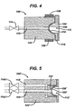
- the one-step process shown in Figs. 4-7 employs a thin-walled mold 100, e.g., a mold having a body 102 that houses a high thermal conductivity forming element 104 to transfer thermal energy to form and set a desired dome shape to the insertion end of a tampon applicator.
- the forming surface 106 is heated to a target temperature, greater than the softening point of a heat-deformable material of the tampon applicator, a portion of the tampon applicator is inserted into the heated thin-walled mold 100 and held stationary to soften petals and form them into a dome shape.
- the forming element 104 is cooled to remove heat from the domed portion of the tampon applicator, thereby setting the domed form of the insertion end. After the domed end is cooled, it is removed from the mold 100.
- Fig. 4 shows a cross-section of a mold body.
- the mold body 102 is heated with an electric band heater 108 to the target temperature. Heat is transferred across a thin cavity (small air gap of the fluid cavity 110) to the forming element 104.
- an insertion end of the applicator (not shown) is inserted into the mold cavity 112, contacting forming surface 106 and allowed to come to softening temperature.
- a valve 114 is opened and a cooling fluid, (e.g., cold air) is supplied through a cooling supply fluid conduit 116 to the fluid cavity 110 of the mold.
- a cooling fluid e.g., cold air
- the cooling fluid passes through the body 102 of the mold to remove heat from the forming element 104 as the fluid passes through the fluid cavity 110, and it exits the body 102 of the mold at port 118.
- the forming surface is preferably heated to a temperature of 100 ⁇ 5° C. Cooling fluid is provided for preferably about one minute or until the mold reaches the preferred temperature of 65 ⁇ 5° C.
- the electric band heater 108 may be switched off during the cooling cycle, alternatively, it may remain on continuously.
- the time required complete a heating and cooling cycle can preferably take approximately two minutes. By optimizing the choice of materials used to make the mold portions, one may influence the cycle time. Additionally, the choice of cooling fluid may affect the cycle time.
- the forming body may preferably be heated for 1 minute and cooled for 1 minute, resulting in a cycle time of 2 minutes.
- FIG. 5 Another mold body is shown in Fig. 5 (and schematically in Fig. 6 ). Heating and cooling of the forming element 104' is accomplished by directing heating and cooling fluids through a single fluid intake conduit 116' to the fluid cavity 110'. As needed, fluid is circulated from either a heating fluid reservoir 120' (heated by heater 121') or cooling fluid reservoir 122' (cooled by chiller 123') through the operation of pumps 125'. The forming element 104' is heated to a target temperature and heat is transferred to the forming surface 106'.
- the process described above is repeated with the heating and cooling of the forming element 104' controlled by supply of heating or cooling fluid by operation of the supply valve 114a' and return valve 114b'.
- the fluid exits the mold body 102' through exit port 118'.
- heating fluids reduces the time required to heat the forming element compared with an external electric band heater.
- complete cycle time is also reduced, and a complete heating and cooling cycle can take less than 30 seconds, and even less than 20 seconds. Again, optimizing the choice of materials used to make the mold portions may influence the cycle time. We have noticed that the heating step often takes more time than the cooling step.
- Figs. 7A-B show the operation of a mold body in which a fluid valve is incorporated within the mold body 102".
- This internal valve e.g., a spool valve 114
- the common fluid path is shortened, which minimizes the mixing of heating and cooling fluids. This, in turn, can reduce the cycle time.
- valve 114" is positioned to provide circulation of heating fluid (darker shading) through heating fluid intake 124", common fluid supply conduit 126" to fluid cavity 110".
- the heating fluid exits the fluid cavity 110" through heating fluid exit conduit 128" and heating fluid exit region 130" of valve 114" and to heating fluid exhaust port 132".
- cooling fluid (lighter shading) circulates through cooling fluid intake 134", cooling fluid bypass conduit 136", cooling fluid bypass region 138" of valve 114" and to cooling fluid exhaust port 140".
- cooling phase shown in Fig.
- 114" is positioned to provide circulation of cooling fluid through cooling fluid intake 134", common fluid supply conduit 126" to fluid cavity 110".
- the cooling fluid exits the fluid cavity 110" through cooling fluid exit conduit 142" and cooling fluid exit region 144" of valve 114" and to cooling fluid exhaust port 140".
- heating fluid circulates through heating fluid intake 124", heating fluid bypass conduit 146", heating fluid bypass region 148" of valve 114" and to heating fluid exhaust port 132".
- the forming element 104" is heated to a target temperature and heat is transferred to the forming surface 106".
- the process described above is repeated with the heating and cooling of the forming element 104" controlled by operation of internal valve 114", as described above.
- heating fluids and the internal valve further reduces the time required to effectively switch between heating and cooling phases of the process compared with the system described in Figure 5 .
- complete cycle time is also reduced, and a complete heating and cooling cycle can take less than 20 seconds, and even less than 15 seconds. Again, optimizing the choice of materials used to make the mold portions may influence the cycle time.
- the resulting temperature profile is shown in Fig. 8 .
- the results show that the mold achieved both the target heating and cooling temperatures within 3 seconds of switching the spooling valve, and the total cycle time is about 13 seconds.
Landscapes
- Health & Medical Sciences (AREA)
- Engineering & Computer Science (AREA)
- Vascular Medicine (AREA)
- Epidemiology (AREA)
- Biomedical Technology (AREA)
- Heart & Thoracic Surgery (AREA)
- Life Sciences & Earth Sciences (AREA)
- Animal Behavior & Ethology (AREA)
- General Health & Medical Sciences (AREA)
- Public Health (AREA)
- Veterinary Medicine (AREA)
- Mechanical Engineering (AREA)
- Manufacturing & Machinery (AREA)
- Absorbent Articles And Supports Therefor (AREA)
Applications Claiming Priority (1)
| Application Number | Priority Date | Filing Date | Title |
|---|---|---|---|
| US12/040,016 US20090218729A1 (en) | 2008-02-29 | 2008-02-29 | Method and apparatus to form a spherical end of an elongated cylindrical tube |
Publications (2)
| Publication Number | Publication Date |
|---|---|
| EP2095801A1 EP2095801A1 (en) | 2009-09-02 |
| EP2095801B1 true EP2095801B1 (en) | 2011-10-12 |
Family
ID=40718778
Family Applications (1)
| Application Number | Title | Priority Date | Filing Date |
|---|---|---|---|
| EP09250601A Not-in-force EP2095801B1 (en) | 2008-02-29 | 2009-03-02 | Method and apparatus to form a spherical end of an elongated cylindrical tube, in particular of a tampon applicator |
Country Status (6)
| Country | Link |
|---|---|
| US (1) | US20090218729A1 (enExample) |
| EP (1) | EP2095801B1 (enExample) |
| JP (1) | JP2009207894A (enExample) |
| AU (1) | AU2009200794A1 (enExample) |
| CA (1) | CA2656464A1 (enExample) |
| MX (1) | MX2009002370A (enExample) |
Families Citing this family (7)
| Publication number | Priority date | Publication date | Assignee | Title |
|---|---|---|---|---|
| WO2012075252A1 (en) | 2010-12-01 | 2012-06-07 | Plasan Carbon Composites, Inc. | Method and system for forming composite articles |
| WO2013040352A1 (en) * | 2011-09-15 | 2013-03-21 | Yoseph Yaacobi | Systems and methods for treating ear disorders |
| WO2013016728A1 (en) * | 2011-07-28 | 2013-01-31 | Plasan Carbon Composites, Inc. | Thermal system and method for rapidly forming composite articles |
| US9868238B1 (en) * | 2013-03-03 | 2018-01-16 | Catheter Dynamics, Inc. | Moldable material shaping systems and methods of use |
| CN105817545B (zh) * | 2016-04-22 | 2017-11-24 | 青岛润泽智能装备股份有限公司 | 一种导管式卫生棉条的导管缩口设备 |
| CN109481151B (zh) * | 2018-12-18 | 2023-07-18 | 孙震 | 一种医用吸液棉生产装置及医用吸液棉生产系统 |
| CN115179536B (zh) * | 2022-07-18 | 2024-03-19 | 上海昊丰医疗科技有限公司 | 一种管材热定型设备 |
Family Cites Families (17)
| Publication number | Priority date | Publication date | Assignee | Title |
|---|---|---|---|---|
| US3433225A (en) * | 1965-12-22 | 1969-03-18 | Joseph A Voss | Hygienic devices and methods of making the same |
| US3895634A (en) * | 1973-10-18 | 1975-07-22 | Rapid American Corp | Tampon inserter |
| JPS55166149A (en) * | 1979-06-12 | 1980-12-25 | Yoshino Kogyosho Co Ltd | Preparation of tampon receiving cylinder |
| US4302174A (en) * | 1979-11-13 | 1981-11-24 | Hauni-Richmond, Inc. | Arrangement for closing the barrels of tampon inserters |
| DE3121364A1 (de) * | 1981-05-29 | 1982-12-16 | Henkel KGaA, 4000 Düsseldorf | "applikator zum hygienischen einfuehren eines tampons" |
| US4453925A (en) * | 1982-02-12 | 1984-06-12 | Sonoco Products Company | Tampon insertion device |
| JPH0717004B2 (ja) | 1986-09-17 | 1995-03-01 | ライオン株式会社 | タンポン挿入具先端部の成形装置 |
| US4836767A (en) * | 1987-11-25 | 1989-06-06 | Husky Injection Molding System, Ltd. | Swing plate molding machine |
| US5290501A (en) * | 1992-05-20 | 1994-03-01 | Playtex Family Products Corporation | Method of forming cardboard tampon applicators having a dome-shaped forward tip |
| JPH07119042B2 (ja) * | 1992-08-11 | 1995-12-20 | 日精樹脂工業株式会社 | 射出成形機の温度制御装置 |
| US5910520A (en) * | 1993-01-15 | 1999-06-08 | Mcneil-Ppc, Inc. | Melt processable biodegradable compositions and articles made therefrom |
| DE19637932C1 (de) * | 1996-09-17 | 1998-02-26 | Johnson & Johnson Gmbh | Verfahren und Einrichtung zum Herstellen eines Tamponapplikators für die Frauenhygiene |
| JP3797835B2 (ja) | 1999-11-19 | 2006-07-19 | ユニ・チャーム株式会社 | タンポン用アプリケータ |
| US6652477B2 (en) * | 2001-08-06 | 2003-11-25 | The Procter & Gamble Company | Tampon applicator with petals |
| EP1424980B1 (en) * | 2001-08-06 | 2009-09-23 | The Procter & Gamble Company | Tampon applicator |
| US7727208B2 (en) | 2002-09-12 | 2010-06-01 | Playtex Products, Inc. | Ergonomic tampon applicator |
| US7098292B2 (en) * | 2003-05-08 | 2006-08-29 | The Procter & Gamble Company | Molded or extruded articles comprising polyhydroxyalkanoate copolymer and an environmentally degradable thermoplastic polymer |
-
2008
- 2008-02-29 US US12/040,016 patent/US20090218729A1/en not_active Abandoned
-
2009
- 2009-02-27 JP JP2009045348A patent/JP2009207894A/ja not_active Abandoned
- 2009-02-27 AU AU2009200794A patent/AU2009200794A1/en not_active Abandoned
- 2009-02-27 CA CA002656464A patent/CA2656464A1/en not_active Abandoned
- 2009-03-02 MX MX2009002370A patent/MX2009002370A/es active IP Right Grant
- 2009-03-02 EP EP09250601A patent/EP2095801B1/en not_active Not-in-force
Also Published As
| Publication number | Publication date |
|---|---|
| MX2009002370A (es) | 2009-08-31 |
| CA2656464A1 (en) | 2009-08-29 |
| JP2009207894A (ja) | 2009-09-17 |
| US20090218729A1 (en) | 2009-09-03 |
| AU2009200794A1 (en) | 2009-09-17 |
| EP2095801A1 (en) | 2009-09-02 |
Similar Documents
| Publication | Publication Date | Title |
|---|---|---|
| EP2095801B1 (en) | Method and apparatus to form a spherical end of an elongated cylindrical tube, in particular of a tampon applicator | |
| AU2004228007B2 (en) | Tampon applicator assembly having an improved plunger and methods of making | |
| CA2629400C (en) | Applicator having an indented fingergrip with raised portions | |
| JP3725383B2 (ja) | タンポン用アプリケータ | |
| EP1521564B1 (en) | Tampon applicator having corrugated grip | |
| US20070032758A1 (en) | Lubricated tampon applicator | |
| JPH05309112A (ja) | 紙製巻込みタンポンチューブの製造方法 | |
| MXPA03008949A (es) | Aplicador que tiene extremo de agarre mejorado. | |
| JP2010506650A (ja) | 膨張性プッシュロッド式金型封止システム及び方法 | |
| CA2586643C (en) | Tampon applicator | |
| US20080154175A1 (en) | Novel Tampon Applicator | |
| US20080228128A1 (en) | Applicator having an intermittent gripping structure | |
| JP4335915B2 (ja) | 安定化したタンポンを製造する方法 | |
| US20050273039A1 (en) | Tampon applicator providing low placement | |
| US20050038373A1 (en) | Process for making an applicator with a locking mechanism comprising a plurality of slits | |
| CA2534783A1 (en) | Applicator with a locking mechanism comprising a plurality of slits |
Legal Events
| Date | Code | Title | Description |
|---|---|---|---|
| PUAI | Public reference made under article 153(3) epc to a published international application that has entered the european phase |
Free format text: ORIGINAL CODE: 0009012 |
|
| AK | Designated contracting states |
Kind code of ref document: A1 Designated state(s): AT BE BG CH CY CZ DE DK EE ES FI FR GB GR HR HU IE IS IT LI LT LU LV MC MK MT NL NO PL PT RO SE SI SK TR |
|
| AX | Request for extension of the european patent |
Extension state: AL BA RS |
|
| RTI1 | Title (correction) |
Free format text: METHOD AND APPARATUS TO FORM A SPHERICAL END OF AN ELONGATED CYLINDRICAL TUBE, IN PARTICULAR OF A TAMPON APPLICATOR |
|
| 17P | Request for examination filed |
Effective date: 20100204 |
|
| 17Q | First examination report despatched |
Effective date: 20100302 |
|
| AKX | Designation fees paid |
Designated state(s): FR GB IT |
|
| REG | Reference to a national code |
Ref country code: DE Ref legal event code: 8566 |
|
| GRAP | Despatch of communication of intention to grant a patent |
Free format text: ORIGINAL CODE: EPIDOSNIGR1 |
|
| GRAS | Grant fee paid |
Free format text: ORIGINAL CODE: EPIDOSNIGR3 |
|
| GRAA | (expected) grant |
Free format text: ORIGINAL CODE: 0009210 |
|
| AK | Designated contracting states |
Kind code of ref document: B1 Designated state(s): FR GB IT |
|
| REG | Reference to a national code |
Ref country code: GB Ref legal event code: FG4D |
|
| PGFP | Annual fee paid to national office [announced via postgrant information from national office to epo] |
Ref country code: FR Payment date: 20120319 Year of fee payment: 4 |
|
| PGFP | Annual fee paid to national office [announced via postgrant information from national office to epo] |
Ref country code: IT Payment date: 20120331 Year of fee payment: 4 |
|
| PLBE | No opposition filed within time limit |
Free format text: ORIGINAL CODE: 0009261 |
|
| STAA | Information on the status of an ep patent application or granted ep patent |
Free format text: STATUS: NO OPPOSITION FILED WITHIN TIME LIMIT |
|
| 26N | No opposition filed |
Effective date: 20120713 |
|
| GBPC | Gb: european patent ceased through non-payment of renewal fee |
Effective date: 20130302 |
|
| REG | Reference to a national code |
Ref country code: FR Ref legal event code: ST Effective date: 20131129 |
|
| PG25 | Lapsed in a contracting state [announced via postgrant information from national office to epo] |
Ref country code: FR Free format text: LAPSE BECAUSE OF NON-PAYMENT OF DUE FEES Effective date: 20130402 Ref country code: GB Free format text: LAPSE BECAUSE OF NON-PAYMENT OF DUE FEES Effective date: 20130302 |
|
| PG25 | Lapsed in a contracting state [announced via postgrant information from national office to epo] |
Ref country code: IT Free format text: LAPSE BECAUSE OF NON-PAYMENT OF DUE FEES Effective date: 20130302 |