EP2095410B1 - Procede et installation de mise a nu de la surface d'un circuit integre - Google Patents
Procede et installation de mise a nu de la surface d'un circuit integre Download PDFInfo
- Publication number
- EP2095410B1 EP2095410B1 EP07871849.1A EP07871849A EP2095410B1 EP 2095410 B1 EP2095410 B1 EP 2095410B1 EP 07871849 A EP07871849 A EP 07871849A EP 2095410 B1 EP2095410 B1 EP 2095410B1
- Authority
- EP
- European Patent Office
- Prior art keywords
- plasma
- integrated circuit
- application
- laser radiation
- circuit
- Prior art date
- Legal status (The legal status is an assumption and is not a legal conclusion. Google has not performed a legal analysis and makes no representation as to the accuracy of the status listed.)
- Active
Links
Images
Classifications
-
- B—PERFORMING OPERATIONS; TRANSPORTING
- B23—MACHINE TOOLS; METAL-WORKING NOT OTHERWISE PROVIDED FOR
- B23K—SOLDERING OR UNSOLDERING; WELDING; CLADDING OR PLATING BY SOLDERING OR WELDING; CUTTING BY APPLYING HEAT LOCALLY, e.g. FLAME CUTTING; WORKING BY LASER BEAM
- B23K26/00—Working by laser beam, e.g. welding, cutting or boring
- B23K26/346—Working by laser beam, e.g. welding, cutting or boring in combination with welding or cutting covered by groups B23K5/00 - B23K25/00, e.g. in combination with resistance welding
- B23K26/348—Working by laser beam, e.g. welding, cutting or boring in combination with welding or cutting covered by groups B23K5/00 - B23K25/00, e.g. in combination with resistance welding in combination with arc heating, e.g. TIG [tungsten inert gas], MIG [metal inert gas] or plasma welding
-
- G—PHYSICS
- G03—PHOTOGRAPHY; CINEMATOGRAPHY; ANALOGOUS TECHNIQUES USING WAVES OTHER THAN OPTICAL WAVES; ELECTROGRAPHY; HOLOGRAPHY
- G03F—PHOTOMECHANICAL PRODUCTION OF TEXTURED OR PATTERNED SURFACES, e.g. FOR PRINTING, FOR PROCESSING OF SEMICONDUCTOR DEVICES; MATERIALS THEREFOR; ORIGINALS THEREFOR; APPARATUS SPECIALLY ADAPTED THEREFOR
- G03F7/00—Photomechanical, e.g. photolithographic, production of textured or patterned surfaces, e.g. printing surfaces; Materials therefor, e.g. comprising photoresists; Apparatus specially adapted therefor
- G03F7/26—Processing photosensitive materials; Apparatus therefor
- G03F7/42—Stripping or agents therefor
- G03F7/427—Stripping or agents therefor using plasma means only
-
- H—ELECTRICITY
- H01—ELECTRIC ELEMENTS
- H01J—ELECTRIC DISCHARGE TUBES OR DISCHARGE LAMPS
- H01J37/00—Discharge tubes with provision for introducing objects or material to be exposed to the discharge, e.g. for the purpose of examination or processing thereof
- H01J37/32—Gas-filled discharge tubes
- H01J37/32009—Arrangements for generation of plasma specially adapted for examination or treatment of objects, e.g. plasma sources
- H01J37/32082—Radio frequency generated discharge
-
- H—ELECTRICITY
- H01—ELECTRIC ELEMENTS
- H01J—ELECTRIC DISCHARGE TUBES OR DISCHARGE LAMPS
- H01J37/00—Discharge tubes with provision for introducing objects or material to be exposed to the discharge, e.g. for the purpose of examination or processing thereof
- H01J37/32—Gas-filled discharge tubes
- H01J37/32431—Constructional details of the reactor
- H01J37/32798—Further details of plasma apparatus not provided for in groups H01J37/3244 - H01J37/32788; special provisions for cleaning or maintenance of the apparatus
- H01J37/32816—Pressure
- H01J37/32825—Working under atmospheric pressure or higher
-
- H—ELECTRICITY
- H01—ELECTRIC ELEMENTS
- H01L—SEMICONDUCTOR DEVICES NOT COVERED BY CLASS H10
- H01L21/00—Processes or apparatus adapted for the manufacture or treatment of semiconductor or solid state devices or of parts thereof
- H01L21/02—Manufacture or treatment of semiconductor devices or of parts thereof
- H01L21/04—Manufacture or treatment of semiconductor devices or of parts thereof the devices having potential barriers, e.g. a PN junction, depletion layer or carrier concentration layer
- H01L21/50—Assembly of semiconductor devices using processes or apparatus not provided for in a single one of the groups H01L21/18 - H01L21/326 or H10D48/04 - H10D48/07 e.g. sealing of a cap to a base of a container
- H01L21/56—Encapsulations, e.g. encapsulation layers, coatings
-
- H—ELECTRICITY
- H01—ELECTRIC ELEMENTS
- H01L—SEMICONDUCTOR DEVICES NOT COVERED BY CLASS H10
- H01L21/00—Processes or apparatus adapted for the manufacture or treatment of semiconductor or solid state devices or of parts thereof
- H01L21/67—Apparatus specially adapted for handling semiconductor or electric solid state devices during manufacture or treatment thereof; Apparatus specially adapted for handling wafers during manufacture or treatment of semiconductor or electric solid state devices or components ; Apparatus not specifically provided for elsewhere
- H01L21/67005—Apparatus not specifically provided for elsewhere
- H01L21/67011—Apparatus for manufacture or treatment
- H01L21/67126—Apparatus for sealing, encapsulating, glassing, decapsulating or the like
-
- H—ELECTRICITY
- H01—ELECTRIC ELEMENTS
- H01L—SEMICONDUCTOR DEVICES NOT COVERED BY CLASS H10
- H01L2924/00—Indexing scheme for arrangements or methods for connecting or disconnecting semiconductor or solid-state bodies as covered by H01L24/00
-
- H—ELECTRICITY
- H01—ELECTRIC ELEMENTS
- H01L—SEMICONDUCTOR DEVICES NOT COVERED BY CLASS H10
- H01L2924/00—Indexing scheme for arrangements or methods for connecting or disconnecting semiconductor or solid-state bodies as covered by H01L24/00
- H01L2924/0001—Technical content checked by a classifier
- H01L2924/0002—Not covered by any one of groups H01L24/00, H01L24/00 and H01L2224/00
Definitions
- the present invention relates to a method of exposing an integrated circuit by ablation of a polymer casing initially covering the integrated circuit.
- the integrated circuits are etched in a silicon block provided with lateral connections made in particular of copper allowing the connection of the internal circuit to a printed circuit carrying other electronic components.
- the integrated circuit is encapsulated in a polymer jacket now rigidly connecting tabs allowing the manipulation of the circuit and ensuring its protection.
- This method is implemented in a specific installation for precisely controlling the application of the laser.
- the laser is applied moderately but islands of polymer remain in place on the circuit, which affects the subsequent observation of the integrated circuit.
- the plasma causes an attack of the polymeric envelope.
- the action of the plasma is very slow and only allows to remove a very small thickness of the plastic envelope.
- the document US 4,689,467 discloses a cutting device of a workpiece made of a single material.
- the device comprises a laser and a plasma gun.
- this laser has a power too high to be used in microelectronics.
- the plasma gun is primarily an auxiliary energy generator that heats the workpiece to cut faster.
- This gun can not be used to expose an integrated circuit because it would have the effect of melting the polymer layer, the connecting conductors as well as the circuit components. Also, such a plasma gun would damage the circuit board not yet integrated.
- a corona discharge i.e., an electric arc is generated to create the plasma.
- Such an electric arc would destroy the integrated circuit if it were used to expose an integrated circuit.
- the jet from the plasma gun has a sanding effect at the atomic scale.
- the cutting device described in this document can not be used to expose an integrated circuit.
- Multichip module packaging of Microelectromechanical systems discloses a method of exposing a micro-wafer of an electromechanical micro-system (MEMS). According to this method, two dielectric layers covering the micro-wafer are removed by ablation when first applying a laser beam and then a plasma etching.
- MEMS electromechanical micro-system
- micro wafer is maintained on the same support and in the same chamber during the application of the laser and the plasma application.
- plasma etching it is no longer possible to perform the plasma etching and exactly at the chosen location, given the size of the portions of the integrated circuit to be treated.
- a flat polishing of the envelope of the integrated circuit is performed from a grinding wheel, thus leaving only a small thickness of the envelope which is then eliminated by the action of plasma.
- most of the thickness of the envelope is removed by etching with an acid and in particular nitric or sulfuric acid.
- the object of the invention is to propose a method for exposing the surface of an integrated circuit that can be implemented quickly while making it possible to obtain a satisfactory surface state of the integrated circuit.
- the subject of the invention is a method of exposing an integrated circuit by ablation of a polymer casing initially covering the integrated circuit, characterized in that it comprises a combined application of laser radiation and a plasma on the envelope initially covering the integrated circuit, the combined application being performed in the same enclosure.
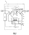
- the installation 10 illustrated on the Figure 1 is able to ensure the exposure of a sample 12 formed of an integrated circuit contained in a polymer envelope by successive implementation of a laser beam and a vacuum plasma.
- the circuit 12 is carried by a plate 13.
- This installation comprises a vacuum chamber 14 defining a sealed enclosure 16.
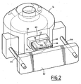
- the chamber 14 is shown in more detail on the Figure 2 .
- the chamber 14 has a flat bottom 18, a generally cylindrical side wall 20 and a lid 27 of generally frustoconical shape surmounted by a flat ceiling 24.
- the ceiling 24 has a transparent window 26 arranged to the right of the central part of the bottom 18 where is the plate 13 on the Figure 1 when it is in the processing position of the circuit.
- a laser source 28 is disposed outside the chamber 14 opposite the window 26 and is turned towards the sample 12.
- This laser is for example a Galvano laser, Nd: Yag type or excimer laser.
- This laser is connected for its control by a central control unit 30.
- the central control unit 30 is formed for example of a computer associated with input and output cards.
- the laser source 28 is carried by means 32 for moving the laser beam in the plane of the circuit 12 in two directions perpendicular to each other. These displacement means are connected to the central control unit 30 for controlling the position of the laser and for scanning the upper surface of the circuit 12 by the laser beam.
- the frustoconical wall 22 of the cover is provided with a transparent window 34 behind which is disposed an observation camera 36 placed outside the enclosure and directed to observe the sample 12 disposed in the pregnant.
- the camera 36 is connected to an observation monitor 38 for monitoring the evolution of the exposed surface of the integrated circuit.
- the optical axis of the camera 36 is angularly offset from normal to the circuit 12.
- an image correction circuit is interposed between the camera 36 and the monitor 38.
- This image correcting circuit is suitable for implementing an image processing algorithm making it possible to straighten the image initially in the form of trapezoid obtained from the circuit so that this image has a rectangular shape as if it had been observed with a camera optical axis perpendicular to the normal to the circuit.
- a mirror or a set of mirrors is disposed inside the enclosure between the camera 36 and the circuit 12, in order to modify the beam between the camera and the circuit and thus ensure, by a correction of the angles, a recovery of the image.
- two cameras with different angles are positioned to observe the circuit. Images obtained by two cameras are sent to an image processing unit for producing a stereoscopic image of the circuit.
- the three preceding approaches are combined.
- two cameras are for example used to obtain a stereoscopic image of the circuit while a third camera is associated with a set of mirrors or an image processing unit in order to obtain a rectangular rectified image of the circuit.
- a nozzle 40 for injecting a cleaning gas is formed through the frustoconical wall 22. This nozzle is directed towards the integrated circuit 12.
- the nozzle 40 is fed from a source 42 of cleaning gas under pressure.
- the supply of the nozzle 40 from the gas contained in the source 32 is controlled by the central control unit 30 driving a valve 44.
- the gas contained in the source 42 projected by the nozzle 40 is for example formed of carbon dioxide suitable for spraying the materials not removed by the plasma.
- the enclosure further comprises means 46 for establishing a plasma on the surface to be exposed of the integrated circuit 12.
- These means 46 comprise a ring 48 for injecting a clean gas to be ionized.
- This ring is disposed along the axis of the chamber inside the chamber in the vicinity of the window 26.
- the ring 48 comprises a set of perforations distributed at its periphery and directed towards the circuit 12.
- the ring 48 is fed by a source of ionization gas 50 disposed outside the chamber to which the ring is connected through a valve 52 controlled by the central control unit 30.
- the gas contained in the source 50 is formed for example of a mixture of oxygen and carbon tetrafluoride.
- the means 46 for establishing a plasma further comprise a radio frequency generator 54 connected to the support plate 13 of the sample.
- This generator 54 is capable of creating an intense electromagnetic field capable of causing the ionization of the gas contained in the chamber.
- the generator 54 is connected for its control to the central control unit 30.
- Suction mouths 56 are disposed in the bottom 18 around the sample 12. These mouths are connected to a vacuum pump 58 controlled by the central control unit 30. The mouths 56 are adapted to suck the gas contained in the chamber and the debris obtained during the dislocation of the envelope under the action of laser radiation and plasma.
- the support plate of the sample 13 is slidably mounted relative to the chamber 14.
- the chamber 14 has in its side wall 20 an introduction opening 60 through which the plate 13 supporting the sample 12 is sliding climb.
- the plate 13 is integral with a sliding drawer 62 movably mounted on two lateral slides 64 secured to the chamber 14.
- the slide 64 is movable between a position of installation of the circuit in which the plate is essentially outside the chamber 14 and the processing position of the circuit in which the plate 13 and in particular the sample are at the right of the window 26.
- the plate 13 and the slide 62 are provided with a seal for sealing the chamber 16 when the plate is in the sample processing position.
- the plate comprises a bracket 66 for positioning the integrated circuit 12.
- a protective mask 68 is finally disposed above the circuit and carried by the plate 13. This mask defines an orifice 70 for the passage of the laser beam and the plasma to the right of the part to be exposed of the integrated circuit.
- the circuit is first positioned on the plate 13 below the mask 68 and the plate is inserted into the chamber.
- the vacuum is then made in the chamber from the pump 58.
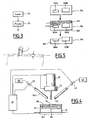
- the surface to be exposed of the integrated circuit is then subjected to laser radiation from the source 28 to the 72 step of the Figure 3 .
- the laser beam used preferably has a power of between 1 and 50 Watts. It is applied for a duration for example between 5 and 30 seconds.
- the laser beam is applied in order to allow ablation of the circuit envelope over most of its thickness, leaving only a residual thickness of between 50 and 200 ⁇ m and preferably equal to 100 ⁇ m.
- the evolution of the circuit is observed from the camera 36.
- the debris of the envelope removed is collected by the mouths 56.
- a plasma is established in the vicinity of the circuit 12 in step 74 without the circuit being removed from the enclosure 16 and while the latter is still under vacuum.
- This plasma is established by injecting gas from the ring 48 and creating a magnetic field by the generator 54.
- the plasma preferably has the characteristics to ensure a dislocation of the resin present.
- the temperature, the working pressure level, and the nature of the gases used are chosen according to the type and the thickness of the resin.
- the presence of the plasma makes it possible, by the action of the ionized particles, a complete elimination of the residual layer of polymer, even in the undercut parts of the circuit and under the copper connections.
- the first step 72 of implementation of the laser radiation is performed while the integrated circuit is subjected to a plasma.
- the successive steps 72 and 74 of applying a laser and a plasma are repeated to enable the ablation of the residual layer in regions where it is thickest through the laser beam, after an earlier action of the laser and the plasma.
- a final plasma treatment step is applied.
- the plasma created in the chamber 16 is maintained not by the creation of a magnetic field by means of the generator 54 but by the subjection to a laser radiation of suitable power, this radiation being suitable for ionizing the gas in the chamber but being insufficient to itself attack the polymer shell.
- the combined use of the laser radiation and the plasma in the same enclosure reduces the manipulations and thus allows a method of bare exposure very fast and easy to implement.
- the fact of remaining under vacuum between the two operations makes it possible not to oxidize the metals constituting the circuit or the connections of the circuit with the ambient air.
- connection son connecting the integrated circuit itself to the lateral connection tabs protruding relative to the housing.
- the action of the laser makes it possible to disengage the upper surface of these connection wires while the polymer located below the connection wires is removed by the action of the plasma, without the connection wires being damaged.
- Such a bare connection son is particularly useful for a subsequent step of tearing test connection son, the results obtained tearing tests not being modified by the aggressive action implemented to remove the polymer.
- the vacuum plasma is replaced by an atmospheric plasma.
- the chamber 14 is removed.
- the sample 12 supported by the plate 13 is as previously arranged facing the laser source 28 and means 40, 42, 44 for injecting a cleaning gas are provided.
- the means for establishing an atmospheric laser comprises a plasma gas release nozzle 100 connected to a source of gas 102 containing oxygen or a mixture of oxygen and carbon tetrafluorides.
- the laser is used as a source of excitation of the injected gas to cause ionization of the plasma gas.
- the method implemented in this installation is identical to that implemented in the installation of the Figure 1 , the circuit 12 is first subjected to laser radiation and then subjected to plasma etching.
- circuits 100A, 100B are commonly called “system in package” (system in a box or SIP) or “multi cheap module” (multi component module or MCM).
- Integrated circuits arranged in such a housing may have upper surfaces located at different levels, especially when the integrated circuits have different thicknesses.
- the housing is first subjected to step 104 to laser radiation to remove most of the thickness of the cover layer.
- the removed portion is noted 105.
- This ablation is performed by several passes made with the laser radiation, the number of passes being greater above the circuit whose upper face is the deepest.
- the laser is applied so as to leave on each of the circuits a residual layer of polymer 102 of substantially the same thickness.
- step 106 the integrated circuits 100A, 100B are subjected to a plasma ensuring the simultaneous ablation of the residual polymer layer remaining above the different circuits.
- the protective mask 68 is initially a solid plate formed of polymer or metal.
- the orifice 70 is directly machined by the laser radiation coming from the laser 28.
- the opening is positioned very precisely and presents an exactly satisfactory shape for the treatment of the circuit placed below.
- Such adjustment is difficult to achieve manually with mechanical positioning of a pre-machined mask.
- the initial orifice 70 is enlarged by the action of the laser.
- the plasma etching carried out during step 74 is a physico-chemical etching (RIE: Reactive Ion Etching).
- RIE Reactive Ion Etching
- the plasma is generated by creating a magnetic field in a gas at a pressure generally ranging from 10mTorr to 1000 mTorr. It is a so-called low pressure plasma.
- the magnetic field is created by the radiofrequency generator 54 connected to electrodes placed in the chamber 16 in the environment of the mixture of oxygen and carbon tetrafluoride at low pressure.
- the magnetic field ionizes the molecules of the gas mixture by stripping them of their electrons, thus creating the plasma.
- the integrated circuit 12 absorbs the free electrons accelerated by the magnetic field so that it charges negatively. On the contrary, plasma is positively charged because of its high concentration of positive ions compared to free electrons. Because of this significant potential difference, positive ions move to circuit 12 where they collide with the residual polymer and the polymer beneath the bonding conductors to chemically etch. The ions react chemically with the residual polymer and eject a portion of this polymer by transferring their kinetic energy.
- the plasma etching is performed during or after the application of the laser while the integrated circuit 12 is held on the same support plate and the latter is not moved.
- the laser radiation is applied until the thickness of the residual polymer layer above the integrated circuit is between 200 ⁇ m and 0 ⁇ m.
- the laser power used is about 0.5 Watts per cm 2 .
- the method of exposing the surface of an integrated circuit is carried out according to the steps described below.
- the sample is an electronic component that has a size of about a few cm 2 .
- This component is embedded in a polymer-based resin (black plastic appearance). This component must be open in order to expose the integrated circuit.
- the integrated circuit is mounted on a generally metal frame on which are the pins (or tabs) of external connections. The connection between the integrated circuit and the pins is made by connecting conductors welded on one side and the other.
- the assembly is embedded in the polymer-based resin leaving only the end of the connection pins exposed.
- the integrated circuit is rarely located exactly in the center and even less in a plane perfectly parallel with the surface of the coating of the component.
- the thickness of the polymer to be removed is therefore not uniform on this surface to expose the surface of the integrated circuit.
- an X-ray image is made of the component so as to estimate the size of the integrated circuit.
- a component-scale image obtained with a calibrated optical camera, the position of the integrated circuit can be measured (viewed from above) in order to reposition the laser application area and plasma with respect to the component itself.
- the integrated circuit has a size of 200 microns x 200 microns.
- the electronic component is then positioned on a plate to be introduced into the device according to the invention.
- the orifice serves to protect the outer pins of the sample.
- the orifice 70 of the protective mask 68 has a size of approximately 1 square millimeter. In this hole, the combined application of the laser and the plasma is performed on a predefined area of the integrated circuit.
- the position measurement of the application zone is then aligned with the component positioned on the support plate 13.
- This positioning can be done in multiple ways. Either with a metrology system that allows the measurement of dimensions with respect to a benchmark of the stage, or with a calibrated optical camera or a motorized laser pointer. Similarly the heights can be measured either with a metrology system (motorized probe) or with an interferometry system, or with a camera equipped with a system calibrated in height.
- the resin thicknesses can not be precisely measured. Also, an area wider than the circuit is cleverly defined on which the laser and / or plasma will be applied.
- a first laser ablation is launched over an area of 220 .mu.m x 220 .mu.m, so as to cover the area of the integrated circuit of 200 microns x 200 microns.
- the operation is stopped to check the resin height removed.
- the height is preferably measured in the chamber 16 so as to eliminate the risk of error repositioning the support plate 13 in the enclosure. Indeed, it is very difficult to reposition a mechanical element to less than a few tens of microns. Such a repositioning would be a risk of error that would hinder the successful opening of the component and the necessary steps would excessively lengthen the total duration of the opening.
- the measurement is done for example with a camera 36 playing on the focus to have a height measurement.
- the resin thickness is 1.5 mm.
- the ablation time is calculated to leave 700 microns of resin.
- the ablation area has a triangular shape, passing through the three corners that are not yet bare.
- a slope is chosen so as to have a greater depth in a corner diametrically opposed to that which is exposed.
- laser ablation is used again. This can in turn be followed by plasma ablation until the circuit is completely exposed.
- the etching speeds can be calibrated by fine measurement steps M1, M2 and M3 for example.
- the precise height between the surface of the coating and the integrated circuit is measured on the first circuit and is used as referenced for the following circuits.
- the ablation can then be started so as to leave about 200 ⁇ m on the entire surface of the circuit.
- the margin 250 ⁇ m instead of 200 ⁇ m
- the margin 50 microns instead of 200 microns
- the plasmas used are etching plasmas. Preferentially a plasma type RIE (Reactive Ion Etching) between these two plasmas is used. However, an Inductively Coupled Plasma (ICP) inductive plasma would obtain very good performances.
- the difference between these two plasmas is between the preparation of the plasma which is done in an outside chamber. The plasma is then transferred by a tube to the chamber where the sample is located, the distance separating the two chambers being typically 10 cm.
- the etching plasmas may have an etching rate of less than 120 ⁇ m per hour.
- the speed is 27 microns per hour.
Landscapes
- Engineering & Computer Science (AREA)
- Physics & Mathematics (AREA)
- Plasma & Fusion (AREA)
- General Physics & Mathematics (AREA)
- Optics & Photonics (AREA)
- Chemical & Material Sciences (AREA)
- Microelectronics & Electronic Packaging (AREA)
- Power Engineering (AREA)
- Manufacturing & Machinery (AREA)
- Condensed Matter Physics & Semiconductors (AREA)
- Analytical Chemistry (AREA)
- Computer Hardware Design (AREA)
- Mechanical Engineering (AREA)
- Drying Of Semiconductors (AREA)
- Laser Beam Processing (AREA)
- Encapsulation Of And Coatings For Semiconductor Or Solid State Devices (AREA)
- Treatments Of Macromolecular Shaped Articles (AREA)
- Internal Circuitry In Semiconductor Integrated Circuit Devices (AREA)
Applications Claiming Priority (2)
| Application Number | Priority Date | Filing Date | Title |
|---|---|---|---|
| FR0611489A FR2911003B1 (fr) | 2006-12-28 | 2006-12-28 | Procede et installation de mise a nu de la surface d'un circuit integre |
| PCT/FR2007/002056 WO2008090281A1 (fr) | 2006-12-28 | 2007-12-12 | Procede et installation de mise a nu de la surface d'un circuit integre |
Publications (2)
| Publication Number | Publication Date |
|---|---|
| EP2095410A1 EP2095410A1 (fr) | 2009-09-02 |
| EP2095410B1 true EP2095410B1 (fr) | 2013-04-10 |
Family
ID=38222717
Family Applications (1)
| Application Number | Title | Priority Date | Filing Date |
|---|---|---|---|
| EP07871849.1A Active EP2095410B1 (fr) | 2006-12-28 | 2007-12-12 | Procede et installation de mise a nu de la surface d'un circuit integre |
Country Status (10)
| Country | Link |
|---|---|
| US (1) | US8555728B2 (enExample) |
| EP (1) | EP2095410B1 (enExample) |
| JP (1) | JP2010515251A (enExample) |
| KR (1) | KR101348971B1 (enExample) |
| CN (1) | CN101611482B (enExample) |
| ES (1) | ES2405745T3 (enExample) |
| FR (1) | FR2911003B1 (enExample) |
| MY (1) | MY156014A (enExample) |
| RU (1) | RU2450386C2 (enExample) |
| WO (1) | WO2008090281A1 (enExample) |
Families Citing this family (9)
| Publication number | Priority date | Publication date | Assignee | Title |
|---|---|---|---|---|
| US8844793B2 (en) * | 2010-11-05 | 2014-09-30 | Raytheon Company | Reducing formation of oxide on solder |
| US8796151B2 (en) * | 2012-04-04 | 2014-08-05 | Ultratech, Inc. | Systems for and methods of laser-enhanced plasma processing of semiconductor materials |
| US9543225B2 (en) * | 2014-04-29 | 2017-01-10 | Lam Research Corporation | Systems and methods for detecting endpoint for through-silicon via reveal applications |
| RU2572290C1 (ru) * | 2014-12-01 | 2016-01-10 | Открытое акционерное общество "Объединенная ракетно-космическая корпорация" (ОАО "ОРКК") | Способ декорпусирования интегральных микросхем |
| KR102065012B1 (ko) * | 2016-07-26 | 2020-01-10 | 에이피시스템 주식회사 | 레이저 처리장치 및 레이저 처리방법 |
| US20210333711A1 (en) * | 2018-08-14 | 2021-10-28 | The Board Of Trustees Of The University Of Illinois | Photoresist-free photolithography, photoprocessing tools, and methods with vuv or deep-uv lamps |
| CN111495880A (zh) * | 2020-04-01 | 2020-08-07 | 武汉大学 | Movcd中的激光等离子复合清洗装置 |
| GB2612360B (en) * | 2021-11-01 | 2025-04-30 | Aquasium Tech Limited | Laser welding apparatus |
| CN116013817B (zh) * | 2023-01-17 | 2024-03-19 | 上海季丰电子股份有限公司 | 芯片封装破除装置及方法 |
Family Cites Families (18)
| Publication number | Priority date | Publication date | Assignee | Title |
|---|---|---|---|---|
| US4689467A (en) * | 1982-12-17 | 1987-08-25 | Inoue-Japax Research Incorporated | Laser machining apparatus |
| US4611919A (en) * | 1984-03-09 | 1986-09-16 | Tegal Corporation | Process monitor and method thereof |
| US4714516A (en) * | 1986-09-26 | 1987-12-22 | General Electric Company | Method to produce via holes in polymer dielectrics for multiple electronic circuit chip packaging |
| JPH01179153A (ja) * | 1988-01-08 | 1989-07-17 | Seiko Instr & Electron Ltd | フォーカスイオンビーム加工装置 |
| JP2854963B2 (ja) * | 1990-11-28 | 1999-02-10 | 株式会社日立製作所 | 固相接合方法および装置 |
| JP4513973B2 (ja) * | 1996-12-04 | 2010-07-28 | セイコーエプソン株式会社 | 半導体装置の製造方法 |
| US6071009A (en) * | 1997-10-03 | 2000-06-06 | Micron Technology, Inc. | Semiconductor wirebond machine leadframe thermal map system |
| JP2001049014A (ja) | 1999-08-10 | 2001-02-20 | Sharp Corp | 有機高分子膜の加工方法およびそれを用いて加工された構造体 |
| JP2002110613A (ja) * | 2000-09-26 | 2002-04-12 | Matsushita Electric Works Ltd | プラズマ洗浄装置及びプラズマ洗浄方法 |
| US6699780B1 (en) * | 2000-10-13 | 2004-03-02 | Bridge Semiconductor Corporation | Method of connecting a conductive trace to a semiconductor chip using plasma undercut etching |
| JP2002222835A (ja) * | 2001-01-25 | 2002-08-09 | Nec Corp | 銅張り樹脂基板の加工方法 |
| US7000313B2 (en) * | 2001-03-08 | 2006-02-21 | Ppg Industries Ohio, Inc. | Process for fabricating circuit assemblies using electrodepositable dielectric coating compositions |
| ATE488614T1 (de) * | 2002-08-28 | 2010-12-15 | Moxtronics Inc | Hybridstrahl-beschichtungssystem und verfahren zur herstellung von zno-schichten |
| US20040150096A1 (en) * | 2003-02-03 | 2004-08-05 | International Business Machines Corporation | Capping coating for 3D integration applications |
| JP2004273771A (ja) * | 2003-03-10 | 2004-09-30 | Fuji Electric Device Technology Co Ltd | 半導体装置の製造方法 |
| RU2272335C2 (ru) * | 2003-11-14 | 2006-03-20 | Юрий Дмитриевич Сасов | Способ испытаний и контроля электронных компонентов |
| US20050221586A1 (en) * | 2003-12-18 | 2005-10-06 | Mulligan Rose A | Methods and apparatus for laser dicing |
| US20060257074A1 (en) * | 2004-09-21 | 2006-11-16 | The Furukawa Electric Co., Ltd. | Semiconductor device, display device and device fabricating method |
-
2006
- 2006-12-28 FR FR0611489A patent/FR2911003B1/fr not_active Expired - Fee Related
-
2007
- 2007-12-12 EP EP07871849.1A patent/EP2095410B1/fr active Active
- 2007-12-12 CN CN200780050958XA patent/CN101611482B/zh not_active Expired - Fee Related
- 2007-12-12 ES ES07871849T patent/ES2405745T3/es active Active
- 2007-12-12 RU RU2009128992/28A patent/RU2450386C2/ru active
- 2007-12-12 JP JP2009543493A patent/JP2010515251A/ja active Pending
- 2007-12-12 MY MYPI20092729A patent/MY156014A/en unknown
- 2007-12-12 US US12/521,444 patent/US8555728B2/en not_active Expired - Fee Related
- 2007-12-12 WO PCT/FR2007/002056 patent/WO2008090281A1/fr not_active Ceased
- 2007-12-12 KR KR1020097015599A patent/KR101348971B1/ko not_active Expired - Fee Related
Also Published As
| Publication number | Publication date |
|---|---|
| KR101348971B1 (ko) | 2014-01-10 |
| FR2911003B1 (fr) | 2009-10-02 |
| WO2008090281A1 (fr) | 2008-07-31 |
| CN101611482B (zh) | 2012-07-25 |
| JP2010515251A (ja) | 2010-05-06 |
| MY156014A (en) | 2015-12-31 |
| US20100154558A1 (en) | 2010-06-24 |
| CN101611482A (zh) | 2009-12-23 |
| FR2911003A1 (fr) | 2008-07-04 |
| KR20090106549A (ko) | 2009-10-09 |
| ES2405745T3 (es) | 2013-06-03 |
| US8555728B2 (en) | 2013-10-15 |
| RU2009128992A (ru) | 2011-02-10 |
| RU2450386C2 (ru) | 2012-05-10 |
| EP2095410A1 (fr) | 2009-09-02 |
Similar Documents
| Publication | Publication Date | Title |
|---|---|---|
| EP2095410B1 (fr) | Procede et installation de mise a nu de la surface d'un circuit integre | |
| US9379015B2 (en) | Wafer processing method | |
| TWI821164B (zh) | 晶圓的加工方法 | |
| JP6355537B2 (ja) | 基板処理装置および基板処理方法 | |
| EP1899082B1 (fr) | Procede et dispositif d'ablation laser d'une couche superficielle d'une paroi, telle qu'un revetement de peinture dans une installation nucleaire | |
| EP1567906B1 (fr) | Procede d obtention d un marquage sur une lentille ophtalmique a basse energie de surface | |
| EP2321216A2 (fr) | Procede et dispositif d'encapsulation de microstructures | |
| WO2013140094A1 (fr) | Procédé de fabrication d'au moins un plot d'assemblage sur un support pour l'auto -assemblage d'une puce de circuit intégré sur le support par formation d'un matériau fluoré entourant le plot et exposition du plot et du matériau fluoré à un traitement ultraviolet en présence d ' ozone | |
| FR2552932A1 (fr) | Appareil de traitement sous vide localise | |
| US10802392B2 (en) | Photomask laser etch | |
| US8043880B2 (en) | Microelectronic device | |
| US20240063295A1 (en) | Pulsed-laser modification of quantum-particle cells | |
| WO1997017163A1 (en) | Process and apparatus for oblique beam revolution, for the effective laser stripping of sidewalls | |
| US6688948B2 (en) | Wafer surface protection method | |
| WO2022096819A1 (fr) | Nettoyage d'un élément optique d'un dispositif de fabrication additive | |
| CH719654A2 (fr) | Procédé et équipement d'usinage correctif de pièces microtechniques. | |
| EP2373435B1 (fr) | Procede d'ablation d'une couche superficielle d'une paroi, et dispositif associe | |
| WO2006075830A1 (en) | Method of processing an object having a passivation layer | |
| EP2654070A1 (fr) | Réacteur plasma de type capacitif pour le dépôt de films minces | |
| KR20240152732A (ko) | 칩의 제조 방법 | |
| JP2008300634A (ja) | 光学結晶体の接合方法 | |
| FR2993484A1 (fr) | Procede de metallisation et dispositif associe | |
| FR2737835A1 (fr) | Circuit electronique a micro-composants encapsule et procede de demontage d'un tel circuit | |
| IL124136A (en) | Process and apparatus for oblique beam revolution, for the effective laser stripping of sidewalls |
Legal Events
| Date | Code | Title | Description |
|---|---|---|---|
| PUAI | Public reference made under article 153(3) epc to a published international application that has entered the european phase |
Free format text: ORIGINAL CODE: 0009012 |
|
| 17P | Request for examination filed |
Effective date: 20090624 |
|
| AK | Designated contracting states |
Kind code of ref document: A1 Designated state(s): AT BE BG CH CY CZ DE DK EE ES FI FR GB GR HU IE IS IT LI LT LU LV MC MT NL PL PT RO SE SI SK TR |
|
| RIN1 | Information on inventor provided before grant (corrected) |
Inventor name: OBEIN, MICHAEL Inventor name: DESPLATS, ROMAIN |
|
| DAX | Request for extension of the european patent (deleted) | ||
| 17Q | First examination report despatched |
Effective date: 20100312 |
|
| GRAP | Despatch of communication of intention to grant a patent |
Free format text: ORIGINAL CODE: EPIDOSNIGR1 |
|
| GRAS | Grant fee paid |
Free format text: ORIGINAL CODE: EPIDOSNIGR3 |
|
| GRAA | (expected) grant |
Free format text: ORIGINAL CODE: 0009210 |
|
| AK | Designated contracting states |
Kind code of ref document: B1 Designated state(s): AT BE BG CH CY CZ DE DK EE ES FI FR GB GR HU IE IS IT LI LT LU LV MC MT NL PL PT RO SE SI SK TR |
|
| REG | Reference to a national code |
Ref country code: GB Ref legal event code: FG4D Free format text: NOT ENGLISH |
|
| REG | Reference to a national code |
Ref country code: CH Ref legal event code: NV Representative=s name: ARNOLD AND SIEDSMA AG, CH Ref country code: AT Ref legal event code: REF Ref document number: 606425 Country of ref document: AT Kind code of ref document: T Effective date: 20130415 Ref country code: CH Ref legal event code: EP |
|
| REG | Reference to a national code |
Ref country code: IE Ref legal event code: FG4D Free format text: LANGUAGE OF EP DOCUMENT: FRENCH |
|
| REG | Reference to a national code |
Ref country code: ES Ref legal event code: FG2A Ref document number: 2405745 Country of ref document: ES Kind code of ref document: T3 Effective date: 20130603 |
|
| REG | Reference to a national code |
Ref country code: DE Ref legal event code: R096 Ref document number: 602007029760 Country of ref document: DE Effective date: 20130606 |
|
| PG25 | Lapsed in a contracting state [announced via postgrant information from national office to epo] |
Ref country code: SI Free format text: LAPSE BECAUSE OF FAILURE TO SUBMIT A TRANSLATION OF THE DESCRIPTION OR TO PAY THE FEE WITHIN THE PRESCRIBED TIME-LIMIT Effective date: 20130410 |
|
| REG | Reference to a national code |
Ref country code: AT Ref legal event code: MK05 Ref document number: 606425 Country of ref document: AT Kind code of ref document: T Effective date: 20130410 |
|
| REG | Reference to a national code |
Ref country code: NL Ref legal event code: VDEP Effective date: 20130410 Ref country code: LT Ref legal event code: MG4D |
|
| PG25 | Lapsed in a contracting state [announced via postgrant information from national office to epo] |
Ref country code: NL Free format text: LAPSE BECAUSE OF FAILURE TO SUBMIT A TRANSLATION OF THE DESCRIPTION OR TO PAY THE FEE WITHIN THE PRESCRIBED TIME-LIMIT Effective date: 20130410 Ref country code: SE Free format text: LAPSE BECAUSE OF FAILURE TO SUBMIT A TRANSLATION OF THE DESCRIPTION OR TO PAY THE FEE WITHIN THE PRESCRIBED TIME-LIMIT Effective date: 20130410 Ref country code: FI Free format text: LAPSE BECAUSE OF FAILURE TO SUBMIT A TRANSLATION OF THE DESCRIPTION OR TO PAY THE FEE WITHIN THE PRESCRIBED TIME-LIMIT Effective date: 20130410 Ref country code: PT Free format text: LAPSE BECAUSE OF FAILURE TO SUBMIT A TRANSLATION OF THE DESCRIPTION OR TO PAY THE FEE WITHIN THE PRESCRIBED TIME-LIMIT Effective date: 20130812 Ref country code: IS Free format text: LAPSE BECAUSE OF FAILURE TO SUBMIT A TRANSLATION OF THE DESCRIPTION OR TO PAY THE FEE WITHIN THE PRESCRIBED TIME-LIMIT Effective date: 20130810 Ref country code: LT Free format text: LAPSE BECAUSE OF FAILURE TO SUBMIT A TRANSLATION OF THE DESCRIPTION OR TO PAY THE FEE WITHIN THE PRESCRIBED TIME-LIMIT Effective date: 20130410 Ref country code: AT Free format text: LAPSE BECAUSE OF FAILURE TO SUBMIT A TRANSLATION OF THE DESCRIPTION OR TO PAY THE FEE WITHIN THE PRESCRIBED TIME-LIMIT Effective date: 20130410 Ref country code: GR Free format text: LAPSE BECAUSE OF FAILURE TO SUBMIT A TRANSLATION OF THE DESCRIPTION OR TO PAY THE FEE WITHIN THE PRESCRIBED TIME-LIMIT Effective date: 20130711 |
|
| PG25 | Lapsed in a contracting state [announced via postgrant information from national office to epo] |
Ref country code: BG Free format text: LAPSE BECAUSE OF FAILURE TO SUBMIT A TRANSLATION OF THE DESCRIPTION OR TO PAY THE FEE WITHIN THE PRESCRIBED TIME-LIMIT Effective date: 20130710 Ref country code: LV Free format text: LAPSE BECAUSE OF FAILURE TO SUBMIT A TRANSLATION OF THE DESCRIPTION OR TO PAY THE FEE WITHIN THE PRESCRIBED TIME-LIMIT Effective date: 20130410 Ref country code: PL Free format text: LAPSE BECAUSE OF FAILURE TO SUBMIT A TRANSLATION OF THE DESCRIPTION OR TO PAY THE FEE WITHIN THE PRESCRIBED TIME-LIMIT Effective date: 20130410 Ref country code: CY Free format text: LAPSE BECAUSE OF FAILURE TO SUBMIT A TRANSLATION OF THE DESCRIPTION OR TO PAY THE FEE WITHIN THE PRESCRIBED TIME-LIMIT Effective date: 20130410 |
|
| PG25 | Lapsed in a contracting state [announced via postgrant information from national office to epo] |
Ref country code: EE Free format text: LAPSE BECAUSE OF FAILURE TO SUBMIT A TRANSLATION OF THE DESCRIPTION OR TO PAY THE FEE WITHIN THE PRESCRIBED TIME-LIMIT Effective date: 20130410 Ref country code: DK Free format text: LAPSE BECAUSE OF FAILURE TO SUBMIT A TRANSLATION OF THE DESCRIPTION OR TO PAY THE FEE WITHIN THE PRESCRIBED TIME-LIMIT Effective date: 20130410 Ref country code: CZ Free format text: LAPSE BECAUSE OF FAILURE TO SUBMIT A TRANSLATION OF THE DESCRIPTION OR TO PAY THE FEE WITHIN THE PRESCRIBED TIME-LIMIT Effective date: 20130410 Ref country code: SK Free format text: LAPSE BECAUSE OF FAILURE TO SUBMIT A TRANSLATION OF THE DESCRIPTION OR TO PAY THE FEE WITHIN THE PRESCRIBED TIME-LIMIT Effective date: 20130410 |
|
| PLBE | No opposition filed within time limit |
Free format text: ORIGINAL CODE: 0009261 |
|
| STAA | Information on the status of an ep patent application or granted ep patent |
Free format text: STATUS: NO OPPOSITION FILED WITHIN TIME LIMIT |
|
| PG25 | Lapsed in a contracting state [announced via postgrant information from national office to epo] |
Ref country code: RO Free format text: LAPSE BECAUSE OF FAILURE TO SUBMIT A TRANSLATION OF THE DESCRIPTION OR TO PAY THE FEE WITHIN THE PRESCRIBED TIME-LIMIT Effective date: 20130410 |
|
| 26N | No opposition filed |
Effective date: 20140113 |
|
| REG | Reference to a national code |
Ref country code: DE Ref legal event code: R097 Ref document number: 602007029760 Country of ref document: DE Effective date: 20140113 |
|
| BERE | Be: lapsed |
Owner name: CENTRE NATIONAL D'ETUDES SPATIALES (C.N.E.S.) Effective date: 20131231 |
|
| PG25 | Lapsed in a contracting state [announced via postgrant information from national office to epo] |
Ref country code: LU Free format text: LAPSE BECAUSE OF FAILURE TO SUBMIT A TRANSLATION OF THE DESCRIPTION OR TO PAY THE FEE WITHIN THE PRESCRIBED TIME-LIMIT Effective date: 20131212 Ref country code: MC Free format text: LAPSE BECAUSE OF FAILURE TO SUBMIT A TRANSLATION OF THE DESCRIPTION OR TO PAY THE FEE WITHIN THE PRESCRIBED TIME-LIMIT Effective date: 20130410 |
|
| PG25 | Lapsed in a contracting state [announced via postgrant information from national office to epo] |
Ref country code: BE Free format text: LAPSE BECAUSE OF NON-PAYMENT OF DUE FEES Effective date: 20131231 |
|
| PG25 | Lapsed in a contracting state [announced via postgrant information from national office to epo] |
Ref country code: TR Free format text: LAPSE BECAUSE OF FAILURE TO SUBMIT A TRANSLATION OF THE DESCRIPTION OR TO PAY THE FEE WITHIN THE PRESCRIBED TIME-LIMIT Effective date: 20130410 |
|
| REG | Reference to a national code |
Ref country code: ES Ref legal event code: FD2A Effective date: 20150715 |
|
| PG25 | Lapsed in a contracting state [announced via postgrant information from national office to epo] |
Ref country code: ES Free format text: LAPSE BECAUSE OF NON-PAYMENT OF DUE FEES Effective date: 20131213 Ref country code: HU Free format text: LAPSE BECAUSE OF FAILURE TO SUBMIT A TRANSLATION OF THE DESCRIPTION OR TO PAY THE FEE WITHIN THE PRESCRIBED TIME-LIMIT; INVALID AB INITIO Effective date: 20071212 |
|
| PG25 | Lapsed in a contracting state [announced via postgrant information from national office to epo] |
Ref country code: MT Free format text: LAPSE BECAUSE OF FAILURE TO SUBMIT A TRANSLATION OF THE DESCRIPTION OR TO PAY THE FEE WITHIN THE PRESCRIBED TIME-LIMIT Effective date: 20130410 |
|
| REG | Reference to a national code |
Ref country code: FR Ref legal event code: PLFP Year of fee payment: 9 |
|
| REG | Reference to a national code |
Ref country code: FR Ref legal event code: PLFP Year of fee payment: 10 |
|
| REG | Reference to a national code |
Ref country code: FR Ref legal event code: PLFP Year of fee payment: 11 |
|
| REG | Reference to a national code |
Ref country code: DE Ref legal event code: R082 Ref document number: 602007029760 Country of ref document: DE Representative=s name: PRINZ & PARTNER MBB PATENTANWAELTE RECHTSANWAE, DE |
|
| PGFP | Annual fee paid to national office [announced via postgrant information from national office to epo] |
Ref country code: DE Payment date: 20201209 Year of fee payment: 14 Ref country code: IE Payment date: 20201123 Year of fee payment: 14 Ref country code: IT Payment date: 20201211 Year of fee payment: 14 Ref country code: CH Payment date: 20201216 Year of fee payment: 14 Ref country code: GB Payment date: 20201217 Year of fee payment: 14 |
|
| REG | Reference to a national code |
Ref country code: DE Ref legal event code: R119 Ref document number: 602007029760 Country of ref document: DE |
|
| REG | Reference to a national code |
Ref country code: CH Ref legal event code: PL |
|
| GBPC | Gb: european patent ceased through non-payment of renewal fee |
Effective date: 20211212 |
|
| PG25 | Lapsed in a contracting state [announced via postgrant information from national office to epo] |
Ref country code: IE Free format text: LAPSE BECAUSE OF NON-PAYMENT OF DUE FEES Effective date: 20211212 Ref country code: GB Free format text: LAPSE BECAUSE OF NON-PAYMENT OF DUE FEES Effective date: 20211212 Ref country code: DE Free format text: LAPSE BECAUSE OF NON-PAYMENT OF DUE FEES Effective date: 20220701 |
|
| PG25 | Lapsed in a contracting state [announced via postgrant information from national office to epo] |
Ref country code: LI Free format text: LAPSE BECAUSE OF NON-PAYMENT OF DUE FEES Effective date: 20211231 Ref country code: CH Free format text: LAPSE BECAUSE OF NON-PAYMENT OF DUE FEES Effective date: 20211231 |
|
| PG25 | Lapsed in a contracting state [announced via postgrant information from national office to epo] |
Ref country code: IT Free format text: LAPSE BECAUSE OF NON-PAYMENT OF DUE FEES Effective date: 20211212 |
|
| PGFP | Annual fee paid to national office [announced via postgrant information from national office to epo] |
Ref country code: FR Payment date: 20241031 Year of fee payment: 18 |