EP2094370B2 - Module filtrant à élément filtrant compressible, et procédé correspondants - Google Patents
Module filtrant à élément filtrant compressible, et procédé correspondants Download PDFInfo
- Publication number
- EP2094370B2 EP2094370B2 EP07857207.0A EP07857207A EP2094370B2 EP 2094370 B2 EP2094370 B2 EP 2094370B2 EP 07857207 A EP07857207 A EP 07857207A EP 2094370 B2 EP2094370 B2 EP 2094370B2
- Authority
- EP
- European Patent Office
- Prior art keywords
- filter element
- filter
- receiving space
- band
- access opening
- Prior art date
- Legal status (The legal status is an assumption and is not a legal conclusion. Google has not performed a legal analysis and makes no representation as to the accuracy of the status listed.)
- Active
Links
- 238000000034 method Methods 0.000 title claims description 18
- 230000006835 compression Effects 0.000 claims description 9
- 238000007906 compression Methods 0.000 claims description 9
- 238000007789 sealing Methods 0.000 claims description 5
- 239000003570 air Substances 0.000 description 12
- 238000004519 manufacturing process Methods 0.000 description 5
- 239000000463 material Substances 0.000 description 5
- 235000019645 odor Nutrition 0.000 description 4
- 239000004831 Hot glue Substances 0.000 description 3
- 239000000853 adhesive Substances 0.000 description 3
- 230000001070 adhesive effect Effects 0.000 description 3
- 238000011161 development Methods 0.000 description 3
- 230000018109 developmental process Effects 0.000 description 3
- 239000002245 particle Substances 0.000 description 3
- 230000001143 conditioned effect Effects 0.000 description 2
- 238000001914 filtration Methods 0.000 description 2
- 238000003780 insertion Methods 0.000 description 2
- 230000037431 insertion Effects 0.000 description 2
- 238000004378 air conditioning Methods 0.000 description 1
- 239000012080 ambient air Substances 0.000 description 1
- 239000012530 fluid Substances 0.000 description 1
- 238000009434 installation Methods 0.000 description 1
- 239000007788 liquid Substances 0.000 description 1
- 230000002040 relaxant effect Effects 0.000 description 1
- 230000000284 resting effect Effects 0.000 description 1
- 238000009423 ventilation Methods 0.000 description 1
Images


Classifications
-
- B—PERFORMING OPERATIONS; TRANSPORTING
- B01—PHYSICAL OR CHEMICAL PROCESSES OR APPARATUS IN GENERAL
- B01D—SEPARATION
- B01D46/00—Filters or filtering processes specially modified for separating dispersed particles from gases or vapours
- B01D46/52—Particle separators, e.g. dust precipitators, using filters embodying folded corrugated or wound sheet material
- B01D46/521—Particle separators, e.g. dust precipitators, using filters embodying folded corrugated or wound sheet material using folded, pleated material
-
- B—PERFORMING OPERATIONS; TRANSPORTING
- B01—PHYSICAL OR CHEMICAL PROCESSES OR APPARATUS IN GENERAL
- B01D—SEPARATION
- B01D46/00—Filters or filtering processes specially modified for separating dispersed particles from gases or vapours
- B01D46/10—Particle separators, e.g. dust precipitators, using filter plates, sheets or pads having plane surfaces
-
- B—PERFORMING OPERATIONS; TRANSPORTING
- B01—PHYSICAL OR CHEMICAL PROCESSES OR APPARATUS IN GENERAL
- B01D—SEPARATION
- B01D46/00—Filters or filtering processes specially modified for separating dispersed particles from gases or vapours
- B01D46/88—Replacing filter elements
-
- B—PERFORMING OPERATIONS; TRANSPORTING
- B01—PHYSICAL OR CHEMICAL PROCESSES OR APPARATUS IN GENERAL
- B01D—SEPARATION
- B01D2275/00—Filter media structures for filters specially adapted for separating dispersed particles from gases or vapours
- B01D2275/20—Shape of filtering material
- B01D2275/203—Shapes flexible in their geometry, e.g. bendable, adjustable to a certain size
Definitions
- the present invention relates to a filter module with a filter element, the filter module having a receiving space with an access opening through which the filter element can be introduced into the receiving space.
- the invention also relates to a method for fastening a filter element in such a filter module.
- a filter element is generally used to filter, for example, fluid flows or gaseous media, such as air flows, which are supplied to the interior of a motor vehicle, for example.
- filters can also be used in many other areas, such as for air conditioning and ventilation systems in buildings.
- a filter element which is used, for example, as a motor vehicle interior air filter, is used to filter the conditioned air that is directed and conditioned from the outside into the interior of the vehicle by means of a suitable filter.
- a suitable filter For example, particle or odor filters or combinations thereof are used, which filter out the particles contained in the air and inherent odors from the ambient air.
- filter receptacles are arranged, for example, in the driver's or front passenger's footwell.
- a filter system is known, with a filter element which is received in a filter receptacle.
- the filter element consists of at least two filter elements which are sealingly arranged in the filter receptacle.
- the filter elements each have a pleated fold pack which is provided with a frame element in a circumferential sealing manner on its two opposite longitudinal sides and on its two end faces.
- the filter receptacle has an access opening for inserting the filter elements.
- the cross-sectional dimensions of an individual filter element are adapted to the clear dimensions of the access opening in such a way that the filter element is no larger than the access opening.
- the filter elements can be arranged next to one another in the receiving space in order to fill it up.
- a pleated filter insert in particular for supply air filters for vehicle interiors, which has a pleated filter with pleats lying transversely to its longitudinal direction.
- the folded filter is provided with a frame element on at least one end face extending transversely to the longitudinal direction.
- the frame element is elastic and allows the pleated filter to be deformed during installation, so that the pleated filter can be inserted through an opening that is smaller than the cross section of the undeformed pleated filter.
- a filter element and a method for its production is known in which a folded filter medium compressed into an elliptical shape is introduced into a likewise compressed, elastic frame and the filter medium is fixed in the frame by relaxing the filter medium and the frame.
- a filter element in which a bellows can be pulled apart in the working position with the aid of a pusher.
- WO 2005/065803 A From the WO 2005/065803 A is a filter element known, in which a compressible and expandable bellows is inserted into a frame.
- the present invention is based on the object of providing a filter module with a filter element, in which the filter element has a larger cross section than an access opening to the receiving space of the filter module in which the filter element is received.
- the above-mentioned object is achieved by a filter module with a filter element having the features of claim 1 and / or by a method having the features of claim 7.
- the idea on which the present invention is based is to provide a filter module with a receiving space for a filter element, wherein the filter element can be compressed so much that it can be introduced into the receiving space through a (significantly) smaller access opening.
- the filter element is also correspondingly elastic, so that in the installed state (after it is no longer compressed) it can expand again and preferably return to its original state.
- the filter element as a whole to be able to be introduced into the receiving space through an access opening which is smaller in comparison therewith.
- the filter element can expand again in the receiving space after it is no longer compressed.
- the size of the filter element is independent of the size of the access opening and can therefore also fill a correspondingly large receiving space behind the access opening alone, without additional filter elements being necessary. This also makes assembly easier.
- the tightness can also be improved, since the filter element only has to lie tightly against the inner contour of the receiving space with its outer contour, in contrast to this when several filter elements are used.
- such a filter element is easy to manufacture and comparatively inexpensive.
- the filter element can be compressed in the longitudinal or width direction or in the transverse direction.
- the filter element is compressible not only in one direction but in two or three of the aforementioned directions. This allows the filter element to be compressed according to the cross section of a smaller access opening.
- the filter element can be at least partially or completely tight against the inner circumference of the receiving space, depending on the requirements that are placed on the filter element.
- the filter of the filter element can be folded not only in a zigzag shape or in an accordion shape or in a wave shape along its longitudinal direction or width direction, but also along the diagonal. This results in further possibilities for the assembly and the later replacement of the filter element.
- a band is provided on the filter element for removing the same from the receiving space of the filter module.
- the band preferably forms a flap or a loop which is arranged in the access opening so that it can be gripped.
- the band can optionally be attached to the respective long side, broad side or diagonal of the filter or at any other point on the filter that enables the filter element to be removed from the receiving space.
- the tape can also be transverse or attached along the folding direction of the filter on the front or back of the filter.
- the tape is attached to the filter by means of an adhesive, for example by means of a hot melt adhesive.
- the band can also be passed through corresponding openings in the filter element.
- the width of the band can be selected to be smaller, equal to or larger than the width of the long side or the wide side of the filter.
- the band can easily protrude laterally over the edges of the long and / or broad side of the filter. This has the advantage that the filter element is protected by the protruding band, particularly when the filter element is installed, but also when it is used later, which is particularly advantageous in the case of very large-area filter elements.
- the filter module according to the invention has a receiving space which, for example, can have a square or polygonal, round or oval cross section.
- the filter element can be adapted to the cross section of the receiving space and therefore also have a square or polygonal, round or oval cross section. In this way, the filter element is optimally adapted to the receiving space of the filter module and can preferably lie tightly against its inner circumferential surface.
- the filter is an odor or. Particulate filter or a combination thereof.
- the filter element has a filter with a zigzag or accordion-shaped and / or undulating fold in the longitudinal direction or the width direction or the diagonal direction, the filter element being compressed transversely to the folding direction in order to be introduced into the filter module through the access opening .
- both ends of the filter element are folded onto one another in order to introduce the filter element through the access opening into the filter module:
- the filter element is at least partially compressed transversely and / or longitudinally to the folding direction for removal from the receiving space of the filter module.
- the ends of the filter element can also be folded onto one another for removal from the receiving space.
- At least one band is additionally provided on the filter element, by means of which the filter element is compressed.
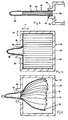
- Fig. 1 shows a perspective view of a first embodiment of a filter element of a filter module according to the invention.
- the filter element is in Fig. 1 denoted by the reference numeral 10. It is assumed that the filter element 10 is designed here as an air filter and in particular as a motor vehicle cabin air filter.
- the filter element 10 is shown in its original state before it is compressed in order to be introduced into a receiving space 12 of the filter module 14. In its original state, the filter element 10 has a larger cross section than an access opening 16 of the receiving space 12, as in FIG Fig. 2 is shown.
- the filter element 10 contains a filter 18, for example an odor and / or particle filter, which is folded in a zigzag shape or in an accordion shape.
- the filter 18 can, however, also be folded in a wave shape, for example (not shown).
- the filter element 10 or its filter 18 is designed to be sufficiently compressible in its longitudinal direction 11 and / or width direction 13 and / or transverse direction 15.
- the filter element 10 or its filter 18 is also designed to be suitably elastic, so that it expands again after the loss of a compression force in order to return at least partially or completely to its original state.
- the band 20 is shown in dashed lines Fig. 1 drawn. According to the invention, the band 20 is designed to be flexible and / or elastic. Furthermore, the band 20 can have the same width as the longitudinal or width side of the filter 18, as in FIG Fig. 1 shown, or a width that is larger or smaller, as in Fig. 6 is shown.
- the band 20 can preferably be attached to the filter 18 in such a way that it forms at least one tab 22 and / or a loop 24 in order to facilitate the removal of the filter element 10 from the receiving space 12.
- the tape 20 can be attached to the filter 18 by means of an adhesive such as a hot melt adhesive, for example a hot melt adhesive, for the preferably sealing connection to the filter 18.
- the tape 20 is attached to at least the folded edges of the filter 18 by means of the adhesive.
- the band 20 can also be used, as will be described below with reference to FIG Figures 7-15 will be explained in more detail, are passed through openings 19 in the filter 18.
- the openings 19 can be additionally sealed from at least one side.
- a strip of filter material (not shown) or another suitable material (not shown) can be glued onto the fold of the filter 18 in such a way that the band 20 runs under the strip, the band 20, as in FIGS Fig. 8 , 11 , 12th and 14th shown can be contracted.
- FIG. 2 an example of a filter module 14 according to the invention with a built-in filter element 10 is shown schematically.
- An inlet and outlet opening on the front and rear of the filter module 14 for the passage of air to be filtered has been omitted for the sake of clarity, as has the tape for later removal of the filter element 10.
- the filter element 10 must first be sufficiently compressed in the width direction 13 and the transverse direction 15 in order to be introduced through the smaller access opening 16.
- the filter element 10 then expands again after the compression force has ceased due to its elasticity in the receiving space 12.
- the receiving space 12 in the interior of the filter module 14 and the built-in filter element 10 are each shown with dashed lines.
- a second embodiment of the filter element 10 is shown.
- the band 20 is attached to the longitudinal sides of the filter element 10 and forms a loop 24 at one end.
- the band 20 can also only be attached to a section of the corresponding longitudinal side of the filter 18.
- the filter 18 of the filter element 10 has a zigzag fold in its longitudinal direction 11.
- the filter element 10 is first compressed in the width direction 13 so that it can be inserted into the access opening 16 in the direction of the arrow and pushed into the receiving space 12.
- the filter element 10 is pushed into the receiving space 12 in such a way that the band 20 or its loop 24 can preferably be gripped in the area of the access opening 16.
- the filter module 14 according to the invention is shown with a built-in filter element 10.
- the filter element 10 unfolds or expands due to its elasticity after it has been inserted into the receiving space 12 and the compression force is eliminated.
- the filter element 10 is preferably dimensioned in such a way that, in the installed state, it rests at least partially or completely against the inner circumference of the receiving space 12, preferably rests tightly. This applies to all embodiments.
- Fig. 5 shows the filter module 14, the filter element 10 being removed from the receiving space 12 in order to replace it with a new filter element 10, for example.
- the loop 24 of the band 20 is pulled in the direction of the arrow, the filter element 10 folding up or being compressed and being easily pulled out through the access opening 16.
- at least one further second opening or removal opening can be provided through which the filter element 10 can be removed.
- the filter element 10 with its band 20 is preferably arranged in the receiving space 12 in such a way that a loop 24 or tab 22 of the band 20 can be easily grasped through the respective opening and pulled out.
- an additional holder 26 or compression aid can optionally be provided in order to make it easier to hold the filter element 10 in a compressed state.
- the holder 26 has a receptacle 28 into which the compressed filter element 10 is inserted.
- the receptacle 28 can for example have a U-shaped cross section corresponding to the filter element 10 and extend at least along a section of the filter element 10. This has the advantage that, in particular, relatively long filter elements 10 can be kept in a compressed state without any problems.
- the filter element 10 By placing or attaching the holder 26 to the access opening 16 of the receiving chamber 12, the filter element 10 can also be more easily inserted into the access opening 16. The filter element 10 is pushed from the holder 26 directly into the access opening 16.
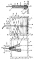
- a third embodiment of the filter element 10 is shown.
- the filter element 10 or its filter 18 is folded in the width direction 13, ie the folds run along the width direction 13.
- At least one band 20 is provided, which runs through the filter element 10 transversely to its fold.
- the band 20 is attached to a broad side of the filter element 10 and runs through corresponding openings 19 in the filter element 10 to the opposite broad side of the filter element 10, as in FIG Figures 7 to 9 is shown.
- the tape 20 can instead be glued at least in sections to the fold of the filter 18 (not shown).
- the filter element 10 is first compressed along its fold in the longitudinal direction 11 and then folded with its two ends 21 on top of each other so that it can be inserted with its closed end into the access opening 16 of the receiving space 12.
- Fig. 8 shows the filter module 14 according to the invention, the filter element 10 expanding or unfolding in the receiving space 12 due to its elasticity after the compression force is removed.
- the folding of the filter element 10 expands in the longitudinal direction 11 along the band 20 to such an extent that the filter element 10 in the installed state rests against the inner circumference of the receiving space 12, for example rests tightly.
- the band 20 forms a tab 22 which is arranged in this way; that it can be easily grasped from the side of the access opening 16.
- Fig. 9 the filter module 14 according to the invention is shown, the filter element 10 being removed from the receiving space 12. To do this, pull tab 22 in the direction of the arrow. In the process, the filter element 10 is compressed and the two ends 21 of the filter element 10 are folded onto one another so that it can easily be removed from the access opening 16.
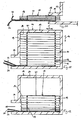
- a fourth embodiment of the filter element 10 is shown.
- the filter element 10 or its filter 18 is folded in the longitudinal direction 11, ie the folds run along the longitudinal direction 11.
- the filter element 10 has a band 20 which runs in two tracks in the width direction 13 through the filter element 10.
- the band 20 is guided through corresponding openings 19 in the filter element 10.
- the band 20 can also be glued accordingly on the front and / or back of the fold of the filter element 10.
- the belt 20 can be provided circumferentially, as in FIG Fig. 11 or, alternatively, two separate straps 20 may be attached to the filter element 10 (not shown).
- the filter element 10 is first compressed in the width direction 13 by pulling the filter element 10 together or compressing it over the band 20 in order to be introduced through the access opening 16 into the receiving space 12.
- Fig. 11 the filter module 14 according to the invention is shown, the filter element 10 being in the installed state. After the band 20 is left loose and as a result there is no longer any compression force acting, the filter element 10 expands again within the receiving space 12 due to its elasticity. The filter element 10 rests against the inner circumferential surface of the receiving space 12.
- Fig. 12 shows the filter module 14, the filter element 10 being removed from the receiving space 12.
- the filter element 10 can be folded up and compressed very easily. The filter element 10 can thereby be conveniently removed through the access opening 16 without damage.
- the filter element 10 or its filter 18 can be folded diagonally instead of, for example, in the longitudinal or width direction 11, 13.
- at least one band 20 can be fastened, for example, in a corner of the filter element 10 and guided through corresponding openings 19 transversely to the fold to the opposite corner of the filter element 10.
- two bands 20 can also be provided, for example, which are arranged to the right and left of the upper corner and each run on a diagonal in the direction of the opposite corner.
- the filter element 10 is, as in Fig. 13 is shown, compressed transversely to the fold before it is inserted into the access opening 16 of the receiving space 12.
- Fig. 14 the filter module 14 is shown in a cross-sectional view, wherein the filter element 10, when the band 20 is left loose, expands due to its elasticity in the receiving space 12.
- Fig. 15 To remove it, as in Fig. 15 is shown, pulled on the tab 22 of the tape 20 in the direction of the arrow. In the process, the filter element 10 is compressed and the two ends 21 are folded onto one another, so that the filter element 10 can easily be removed from the access opening 16.
- the present invention is not restricted to the embodiments and variants described in the above exemplary embodiments.
- the present invention is not limited to the manner in which the filter element 10 is folded.
- the embodiments described above merely represent a few exemplary examples.
- the invention is not limited to the number, arrangement and type of fastening of the band 20 or the bands 20, as they are described in the exemplary embodiments.
- the invention is not limited to filters 18 for filtering gaseous media, but can also be used very advantageously for filters for filtering liquids.
- the invention is also not necessarily restricted to filters 18 for the motor vehicle sector, but can also be used advantageously in any applications in which filters are used.
- the representation of the thickness of the filter material in the figures is not to scale.
- the filter material can have any suitable thickness for the particular application.
- the filter material can be somewhat thinner, as indicated by way of example in the figures, or it can also be made considerably thicker.
- At least one further opening can also be provided in the receiving space 12, through which the filter element 10 can be inserted and / or removed.
- a corresponding band 20 with a tab 22 or a loop 24 can optionally be provided for each of the openings, so that the filter element 10 can easily be inserted and / or removed from each of the openings.
- the position of the access opening 16 or the additional openings can be provided at any point on the filter module 14 that is suitable for installing or removing the filter element 10.
- the receiving chamber 12 can have a square cross-section, as is shown, for example, in FIGS Fig. 2 , 4 and 5 is shown, have any cross-section, for example a circular, oval, triangular or polygonal cross-section.
- the shape or cross section of the filter element 10 is preferably adapted to the respective cross section of the receiving space 12.
Landscapes
- Chemical & Material Sciences (AREA)
- Chemical Kinetics & Catalysis (AREA)
- Filtering Of Dispersed Particles In Gases (AREA)
Claims (16)
- Module filtrant (14) présentant un élément filtrant (10), une ouverture d'accès (16) et un logement (12) permettant de réceptionner l'élément filtrant (10),- l'élément filtrant (10) présentant, dans son état d'origine, une section supérieure à l'ouverture d'accès (16),- l'élément filtrant (10) se prêtant à être comprimé de manière à ce que l'élément filtrant (10) puisse être introduit, à travers l'ouverture d'accès (16), dans le logement (12), et- l'élément filtrant (10) étant exécuté de façon suffisamment élastique pour se dilater à nouveau après avoir été comprimé, caractérisé en ce qu'au moins une bande (20) qui forme au moins une patte (22) et/ou une boucle (24) est prévue sur le filtre (18), cette bande servant à retirer l'élément filtrant (10) du logement (12) et l'élément filtrant (10) est pourvu d'un filtre (18) qui présente un pli en zigzag ou en accordéon et/ou ondulé dans le sens de la longueur ou dans le sens de la largeur et/ou en sens diagonal,- dans lequel la patte (22) et/ou la boucle (24) est disposée de manière saisissable dans l'ouverture d'accès (16) et l'élément de filtre (10) peut être tiré hors du logement (12) par la bande.
- Module filtrant selon la revendication 1, caractérisé en ce que l'élément filtrant (10) peut être comprimé dans le sens de la longueur et/ou dans le sens de la largeur et/ou en sens transversal.
- Module filtrant selon la revendication 1 ou 2, caractérisé en ce que l'élément filtrant (10) est appliqué, au moins en partie ou en totalité, de préférence de manière étanche, sur la circonférence intérieure du logement (12).
- Module filtrant selon l'une des revendications précédentes, caractérisé en ce que la bande (20) est fixée au moins sur un côté longitudinal et/ou sur la diagonale du filtre (18).
- Module filtrant selon l'une des revendications précédentes, caractérisé en ce qu'au moins une bande (20) est fixée sur la face avant et/ou sur la face arrière du filtre, en travers et/ou en sens longitudinal par rapport au sens de pliage du filtre (18).
- Module filtrant selon l'une des revendications précédentes, caractérisé en ce qu'au moins une bande (20) est acheminée à travers des ouvertures correspondantes (19) ménagées dans le filtre (18), en travers et/ou en sens longitudinal par rapport au sens de pliage du filtre.
- Procédé de fixation d'un élément filtrant (10) présentant un élément filtrant (10), une ouverture d'accès (16) et un logement (12) permettant de réceptionner l'élément filtrant (10),- l'élément filtrant (10) présentant, dans son état d'origine, une section supérieure à l'ouverture d'accès (16),- l'élément filtrant (10) se prêtant à être comprimé de manière à ce que l'élément filtrant (10) puisse être introduit, à travers l'ouverture d'accès (16), dans le logement (12), et- l'élément filtrant (10) étant exécuté de façon suffisamment élastique pour se dilater à nouveau après avoir été comprimé, caractérisé en ce qu'au moins une bande (20) qui forme au moins une patte (22) et/ou une boucle (24) est prévue sur le filtre (18), cette bande servant à retirer l'élément filtrant (10) du logement (12) et l'élément filtrant (10) est pourvu d'un filtre (18) qui présente un pli en zigzag ou en accordéon et/ou ondulés dans le sens de la longueur ou dans le sens de la largeur et/ou en sens diagonal,caractérisé en ce qu'au moins une bande (20) est prévue, en complément, sur l'élément filtrant (10) pour la compression et/ou la dilatation de l'élément filtrant (10).
le procédé comprenant les opérations suivantes:- compression de l'élément filtrant (10) en vue d'introduire l'élément filtrant (10), à travers une ouverture d'accès (16), dans un logement (12) du module filtrant (14), et- dilatation de l'élément filtrant (10) dans le logement (12), - Procédé selon la revendication 7, caractérisé en ce que l'élément filtrant (10) est comprimé en travers du sens de pliage afin d'être introduit, à travers l'ouverture d'accès (16), dans le module filtrant (14).
- Procédé selon la revendication 8, caractérisé en ce qu'après l'opération de compression de l'élément filtrant (10) en travers du sens de pliage, les deux extrémités (21) de l'élément filtrant (10) sont pliées l'une sur l'autre dans l'objectif d'introduire l'élément filtrant (10), à travers l'ouverture d'accès (16), dans le module filtrant (14).
- Procédé selon l'une des revendications 7 à 9, caractérisé en ce que l'élément filtrant (10) est comprimé, au moins en partie, en travers et/ou en sens longitudinal par rapport au sens de pliage afin d'être retiré du logement (12) du module filtrant (14).
- Procédé selon la revendication 10, caractérisé en ce que les extrémités (21) de l'élément filtrant (10) sont également pliées l'une sur l'autre afin de retirer l'élément filtrant du logement (12).
- Procédé selon l'une des revendications 7 à 11, caractérisé en ce que l'élément filtrant (10) est compressible dans le sens de la longueur et/ou de la largeur et/ou dans le sens transversal.
- Procédé selon l'une des revendications 7 à 12, caractérisé en ce que l'élément filtrant (10) s'appuie sur la circonférence intérieure du logement (12), au moins partiellement ou complètement, de préférence de manière étanche.
- Procédé selon l'une des revendications 7 à 13, caractérisé en ce que la bande (20) est fixée sur au moins un côté longitudinal et/ou un côté en largeur et/ou une diagonale du filtre (18).
- Procédé selon l'une des revendications 7 à 14, caractérisé en ce qu'au moins une bande (20) est fixée transversalement et/ou longitudinalement à la direction de pliage du filtre (18) sur sa face avant et/ou arrière.
- Procédé selon l'une des revendications 7 à 15, caractérisé en ce qu'au moins une bande (20) est passée à travers des ouvertures correspondantes (19) du filtre (18) transversalement et/ou longitudinalement à sa direction de pliage.
Priority Applications (1)
| Application Number | Priority Date | Filing Date | Title |
|---|---|---|---|
| PL07857207T PL2094370T3 (pl) | 2006-11-09 | 2007-11-09 | Moduł filtracyjny ze ściśliwym i samorozszerzalnym elementem filtracyjnym, zamocowanie i sposób |
Applications Claiming Priority (2)
| Application Number | Priority Date | Filing Date | Title |
|---|---|---|---|
| DE202006017226U DE202006017226U1 (de) | 2006-11-09 | 2006-11-09 | Filtermodul mit einem kompressiblen Filterelement, Halterung |
| PCT/EP2007/062122 WO2008055971A1 (fr) | 2006-11-09 | 2007-11-09 | Module filtrant à élément filtrant compressible, dispositif support et procédé correspondants |
Publications (3)
| Publication Number | Publication Date |
|---|---|
| EP2094370A1 EP2094370A1 (fr) | 2009-09-02 |
| EP2094370B1 EP2094370B1 (fr) | 2014-05-14 |
| EP2094370B2 true EP2094370B2 (fr) | 2021-09-08 |
Family
ID=39111659
Family Applications (1)
| Application Number | Title | Priority Date | Filing Date |
|---|---|---|---|
| EP07857207.0A Active EP2094370B2 (fr) | 2006-11-09 | 2007-11-09 | Module filtrant à élément filtrant compressible, et procédé correspondants |
Country Status (5)
| Country | Link |
|---|---|
| EP (1) | EP2094370B2 (fr) |
| JP (1) | JP2010509045A (fr) |
| DE (1) | DE202006017226U1 (fr) |
| PL (1) | PL2094370T3 (fr) |
| WO (1) | WO2008055971A1 (fr) |
Families Citing this family (9)
| Publication number | Priority date | Publication date | Assignee | Title |
|---|---|---|---|---|
| DE102009051987A1 (de) * | 2009-11-05 | 2011-05-12 | Valeo Klimasysteme Gmbh | Filterbaugruppe einer Fahrzeugheizungs- oder -klima-anlage, Filtereinheit hierfür und Verfahren zur Herstellung der Filterbaugruppe |
| DE102010045486B4 (de) | 2010-09-16 | 2018-08-23 | Mann+Hummel Gmbh | Innenraumluftfilter und Filteranordnung |
| DE102011085446A1 (de) * | 2011-10-28 | 2013-05-02 | Mahle International Gmbh | Filtereinrichtung und zugehöriges Herstellungsverfahren |
| DE102017205147B4 (de) * | 2017-03-27 | 2019-04-04 | Continental Automotive Gmbh | Verfahren zur Herstellung eines Wabenkörpers |
| DE102017007497A1 (de) | 2017-08-08 | 2019-02-14 | Daimler Ag | Filterelement für einen Luftfilter eines Kraftwagens und Luftfilter |
| JP7127276B2 (ja) * | 2017-11-30 | 2022-08-30 | 株式会社デンソー | 車両用エアフィルタ及び車両用空調装置 |
| DE102018218949B4 (de) | 2018-11-07 | 2023-02-16 | Volkswagen Aktiengesellschaft | Filtermodul, Reinigungssystem und Fahrzeug |
| DE102020107345A1 (de) * | 2020-03-17 | 2021-09-23 | Mann+Hummel Gmbh | Aerosolabscheider sowie Verfahren zum Einbau eines Koaleszenz-Filterelementes in einen Aerosolabscheider |
| CN113019002B (zh) * | 2021-03-30 | 2022-08-19 | 苏州市宽道模具机械有限公司 | 一种节能型便于拆装维修的工业用空气滤清器 |
Family Cites Families (20)
| Publication number | Priority date | Publication date | Assignee | Title |
|---|---|---|---|---|
| JPS6274428A (ja) * | 1985-09-28 | 1987-04-06 | Amano Corp | 集塵機用成形フイルタ− |
| JPS62174608U (fr) * | 1986-04-21 | 1987-11-06 | ||
| US4976857A (en) * | 1989-05-03 | 1990-12-11 | Newport Filters, Inc. | Filter element and fabrication methodology |
| JP2746032B2 (ja) * | 1992-12-22 | 1998-04-28 | 三菱電機株式会社 | 換気装置のエアーフィルタ |
| JPH08131744A (ja) * | 1994-10-31 | 1996-05-28 | Tsuchiya Mfg Co Ltd | フィルタエレメント |
| JP3218218B2 (ja) * | 1997-03-31 | 2001-10-15 | 株式会社テネックス | 室内空気処理用のフィルタ |
| GB9803926D0 (en) * | 1998-02-25 | 1998-04-22 | Rover Group | A filter unit |
| JPH11276833A (ja) * | 1998-03-31 | 1999-10-12 | Tennex Corp | 室内空気処理用のフィルタ部材 |
| JP3751165B2 (ja) * | 1999-08-13 | 2006-03-01 | 日本バイリーン株式会社 | エアフィルタ及びその枠体、並びにフィルタエレメントの装着方法 |
| JP2001170433A (ja) * | 1999-12-21 | 2001-06-26 | Yamatoyo Sangyo Kk | 空気清浄用フィルター装置 |
| JP2002210319A (ja) * | 2001-01-22 | 2002-07-30 | Toyo Roki Mfg Co Ltd | フィルタ |
| PL367425A1 (en) * | 2001-10-09 | 2005-02-21 | Carrier Corporation | Expandable and disposable media filter |
| JP2004089982A (ja) * | 2002-03-29 | 2004-03-25 | Mitsubishi Paper Mills Ltd | 空気清浄化フィルター |
| US6740137B2 (en) * | 2002-06-14 | 2004-05-25 | 3M Innovative Properties Company | Collapsible pleated filter element |
| JP4182332B2 (ja) * | 2002-08-29 | 2008-11-19 | 日本バイリーン株式会社 | フィルタ材、及びその製造方法、並びにフィルタ材を取り替え自在に装着したフィルタ装置 |
| US20040182055A1 (en) * | 2003-03-03 | 2004-09-23 | Fedders Corporation | Disposable expandable air filter |
| DE10320260C5 (de) | 2003-03-17 | 2008-09-11 | Helsa-Automotive Gmbh & Co. Kg | Filter für eine Filteraufnahme, insbesondere für eine in einem Kraftfahrzeug vorgesehene Filteraufnahme |
| US7169202B2 (en) * | 2003-12-24 | 2007-01-30 | 3M Innovative Properties Company | Filter assembly |
| DE102004034302A1 (de) * | 2004-07-15 | 2006-02-09 | Mann + Hummel Gmbh | Faltenfiltereinsatz |
| JP2007021455A (ja) * | 2005-07-21 | 2007-02-01 | Toyobo Co Ltd | 復元性フィルター |
-
2006
- 2006-11-09 DE DE202006017226U patent/DE202006017226U1/de not_active Expired - Lifetime
-
2007
- 2007-11-09 PL PL07857207T patent/PL2094370T3/pl unknown
- 2007-11-09 JP JP2009535739A patent/JP2010509045A/ja active Pending
- 2007-11-09 EP EP07857207.0A patent/EP2094370B2/fr active Active
- 2007-11-09 WO PCT/EP2007/062122 patent/WO2008055971A1/fr active Application Filing
Also Published As
| Publication number | Publication date |
|---|---|
| EP2094370A1 (fr) | 2009-09-02 |
| EP2094370B1 (fr) | 2014-05-14 |
| WO2008055971A1 (fr) | 2008-05-15 |
| JP2010509045A (ja) | 2010-03-25 |
| DE202006017226U1 (de) | 2008-03-20 |
| PL2094370T3 (pl) | 2014-10-31 |
Similar Documents
| Publication | Publication Date | Title |
|---|---|---|
| EP2094370B2 (fr) | Module filtrant à élément filtrant compressible, et procédé correspondants | |
| EP2463009B1 (fr) | Ensemble filtre | |
| EP2135662B1 (fr) | Elément filtrant compressible avec des capuchons d'extrémité inclinés les uns vers les autres | |
| EP2127724B1 (fr) | Elément de filtre | |
| DE4430333A1 (de) | Filter | |
| EP2176097B1 (fr) | Elément filtrant et système filtrant | |
| DE102015112113A1 (de) | Filterstrukturkörper und Filtermodul zum Abscheiden von Verunreinigungen aus einem Rohgasstrom | |
| DE102009035979B4 (de) | Filtersystem | |
| DE102007016161A1 (de) | Filtersystem, das aus mehreren Filterelementen besteht, und Herstellungsverfahren | |
| DE102009042588B4 (de) | Filtersystem mit wenigstens einem Rahmenelement an seinem Längsrand | |
| EP0900585A1 (fr) | Dispositif de filtration | |
| DE102017219009A1 (de) | Filterverbund zum Verbau in einem Fahrzeug | |
| EP3698861A1 (fr) | Dispositif filtrant | |
| DE19503024C5 (de) | Luftfilter | |
| EP2452739B1 (fr) | Filtre à air ambiant et agencement de filtre | |
| EP0727246A1 (fr) | Filtre à air pour l'habitacle d'un véhicule automobile | |
| DE102010045486B4 (de) | Innenraumluftfilter und Filteranordnung | |
| DE102007057384A1 (de) | Verfahren zum Herstellen eines Filterelements und Filterelement | |
| DE10241748A1 (de) | Filterelement | |
| EP0666096B1 (fr) | Cadre de changement | |
| DE60132530T2 (de) | Filtervorrichtung für ein Gerät zur Belüftung und/oder zur Beheizung und/oder zur Klimatisierung, insbesondere für ein Kraftfahrzeug und Verwendung solch einer Filtervorrichtung | |
| DE102017221592A1 (de) | Plattenfilterelement für eine Luftfiltereinrichtung | |
| DE10235122B3 (de) | Flexibler Filter | |
| EP1400273B1 (fr) | Élément de filtration | |
| DE102016202673A1 (de) | Filtereinrichtung mit zwei Filtereinsätzen und zugehöriges Herstellungsverfahren |
Legal Events
| Date | Code | Title | Description |
|---|---|---|---|
| PUAI | Public reference made under article 153(3) epc to a published international application that has entered the european phase |
Free format text: ORIGINAL CODE: 0009012 |
|
| 17P | Request for examination filed |
Effective date: 20090518 |
|
| AK | Designated contracting states |
Kind code of ref document: A1 Designated state(s): AT BE BG CH CY CZ DE DK EE ES FI FR GB GR HU IE IS IT LI LT LU LV MC MT NL PL PT RO SE SI SK TR |
|
| DAX | Request for extension of the european patent (deleted) | ||
| 17Q | First examination report despatched |
Effective date: 20110713 |
|
| REG | Reference to a national code |
Ref country code: DE Ref legal event code: R079 Ref document number: 502007013131 Country of ref document: DE Free format text: PREVIOUS MAIN CLASS: B01D0046520000 Ipc: B01D0046000000 |
|
| RIC1 | Information provided on ipc code assigned before grant |
Ipc: B01D 46/52 20060101ALI20130820BHEP Ipc: B01D 46/10 20060101ALI20130820BHEP Ipc: B01D 46/00 20060101AFI20130820BHEP |
|
| GRAP | Despatch of communication of intention to grant a patent |
Free format text: ORIGINAL CODE: EPIDOSNIGR1 |
|
| INTG | Intention to grant announced |
Effective date: 20131029 |
|
| GRAP | Despatch of communication of intention to grant a patent |
Free format text: ORIGINAL CODE: EPIDOSNIGR1 |
|
| INTG | Intention to grant announced |
Effective date: 20131205 |
|
| GRAS | Grant fee paid |
Free format text: ORIGINAL CODE: EPIDOSNIGR3 |
|
| GRAA | (expected) grant |
Free format text: ORIGINAL CODE: 0009210 |
|
| STAA | Information on the status of an ep patent application or granted ep patent |
Free format text: STATUS: THE PATENT HAS BEEN GRANTED |
|
| RIN1 | Information on inventor provided before grant (corrected) |
Inventor name: VOLKMER, DANIEL Inventor name: AUER, HARALD Inventor name: SCOPE, ANDREAS |
|
| AK | Designated contracting states |
Kind code of ref document: B1 Designated state(s): AT BE BG CH CY CZ DE DK EE ES FI FR GB GR HU IE IS IT LI LT LU LV MC MT NL PL PT RO SE SI SK TR |
|
| REG | Reference to a national code |
Ref country code: GB Ref legal event code: FG4D Free format text: NOT ENGLISH |
|
| RIN2 | Information on inventor provided after grant (corrected) |
Inventor name: VOLKMER, DANIEL Inventor name: AUER, HARALD Inventor name: SCOPE, ANDREAS |
|
| REG | Reference to a national code |
Ref country code: AT Ref legal event code: REF Ref document number: 667804 Country of ref document: AT Kind code of ref document: T Effective date: 20140615 |
|
| REG | Reference to a national code |
Ref country code: IE Ref legal event code: FG4D Free format text: LANGUAGE OF EP DOCUMENT: GERMAN |
|
| REG | Reference to a national code |
Ref country code: DE Ref legal event code: R096 Ref document number: 502007013131 Country of ref document: DE Effective date: 20140626 |
|
| REG | Reference to a national code |
Ref country code: NL Ref legal event code: VDEP Effective date: 20140514 |
|
| REG | Reference to a national code |
Ref country code: LT Ref legal event code: MG4D |
|
| PG25 | Lapsed in a contracting state [announced via postgrant information from national office to epo] |
Ref country code: GR Free format text: LAPSE BECAUSE OF FAILURE TO SUBMIT A TRANSLATION OF THE DESCRIPTION OR TO PAY THE FEE WITHIN THE PRESCRIBED TIME-LIMIT Effective date: 20140815 Ref country code: FI Free format text: LAPSE BECAUSE OF FAILURE TO SUBMIT A TRANSLATION OF THE DESCRIPTION OR TO PAY THE FEE WITHIN THE PRESCRIBED TIME-LIMIT Effective date: 20140514 Ref country code: IS Free format text: LAPSE BECAUSE OF FAILURE TO SUBMIT A TRANSLATION OF THE DESCRIPTION OR TO PAY THE FEE WITHIN THE PRESCRIBED TIME-LIMIT Effective date: 20140914 Ref country code: LT Free format text: LAPSE BECAUSE OF FAILURE TO SUBMIT A TRANSLATION OF THE DESCRIPTION OR TO PAY THE FEE WITHIN THE PRESCRIBED TIME-LIMIT Effective date: 20140514 Ref country code: CY Free format text: LAPSE BECAUSE OF FAILURE TO SUBMIT A TRANSLATION OF THE DESCRIPTION OR TO PAY THE FEE WITHIN THE PRESCRIBED TIME-LIMIT Effective date: 20140514 |
|
| REG | Reference to a national code |
Ref country code: PL Ref legal event code: T3 |
|
| PG25 | Lapsed in a contracting state [announced via postgrant information from national office to epo] |
Ref country code: ES Free format text: LAPSE BECAUSE OF FAILURE TO SUBMIT A TRANSLATION OF THE DESCRIPTION OR TO PAY THE FEE WITHIN THE PRESCRIBED TIME-LIMIT Effective date: 20140514 Ref country code: LV Free format text: LAPSE BECAUSE OF FAILURE TO SUBMIT A TRANSLATION OF THE DESCRIPTION OR TO PAY THE FEE WITHIN THE PRESCRIBED TIME-LIMIT Effective date: 20140514 Ref country code: SE Free format text: LAPSE BECAUSE OF FAILURE TO SUBMIT A TRANSLATION OF THE DESCRIPTION OR TO PAY THE FEE WITHIN THE PRESCRIBED TIME-LIMIT Effective date: 20140514 |
|
| PG25 | Lapsed in a contracting state [announced via postgrant information from national office to epo] |
Ref country code: PT Free format text: LAPSE BECAUSE OF FAILURE TO SUBMIT A TRANSLATION OF THE DESCRIPTION OR TO PAY THE FEE WITHIN THE PRESCRIBED TIME-LIMIT Effective date: 20140915 |
|
| PG25 | Lapsed in a contracting state [announced via postgrant information from national office to epo] |
Ref country code: SK Free format text: LAPSE BECAUSE OF FAILURE TO SUBMIT A TRANSLATION OF THE DESCRIPTION OR TO PAY THE FEE WITHIN THE PRESCRIBED TIME-LIMIT Effective date: 20140514 Ref country code: EE Free format text: LAPSE BECAUSE OF FAILURE TO SUBMIT A TRANSLATION OF THE DESCRIPTION OR TO PAY THE FEE WITHIN THE PRESCRIBED TIME-LIMIT Effective date: 20140514 Ref country code: DK Free format text: LAPSE BECAUSE OF FAILURE TO SUBMIT A TRANSLATION OF THE DESCRIPTION OR TO PAY THE FEE WITHIN THE PRESCRIBED TIME-LIMIT Effective date: 20140514 Ref country code: RO Free format text: LAPSE BECAUSE OF FAILURE TO SUBMIT A TRANSLATION OF THE DESCRIPTION OR TO PAY THE FEE WITHIN THE PRESCRIBED TIME-LIMIT Effective date: 20140514 Ref country code: CZ Free format text: LAPSE BECAUSE OF FAILURE TO SUBMIT A TRANSLATION OF THE DESCRIPTION OR TO PAY THE FEE WITHIN THE PRESCRIBED TIME-LIMIT Effective date: 20140514 |
|
| REG | Reference to a national code |
Ref country code: DE Ref legal event code: R026 Ref document number: 502007013131 Country of ref document: DE |
|
| PLBI | Opposition filed |
Free format text: ORIGINAL CODE: 0009260 |
|
| PG25 | Lapsed in a contracting state [announced via postgrant information from national office to epo] |
Ref country code: NL Free format text: LAPSE BECAUSE OF FAILURE TO SUBMIT A TRANSLATION OF THE DESCRIPTION OR TO PAY THE FEE WITHIN THE PRESCRIBED TIME-LIMIT Effective date: 20140514 |
|
| 26 | Opposition filed |
Opponent name: VALEO SYSTEMES THERMIQUES S.A.S. Effective date: 20150213 |
|
| PLAX | Notice of opposition and request to file observation + time limit sent |
Free format text: ORIGINAL CODE: EPIDOSNOBS2 |
|
| REG | Reference to a national code |
Ref country code: DE Ref legal event code: R026 Ref document number: 502007013131 Country of ref document: DE Effective date: 20150213 |
|
| PG25 | Lapsed in a contracting state [announced via postgrant information from national office to epo] |
Ref country code: MC Free format text: LAPSE BECAUSE OF FAILURE TO SUBMIT A TRANSLATION OF THE DESCRIPTION OR TO PAY THE FEE WITHIN THE PRESCRIBED TIME-LIMIT Effective date: 20140514 Ref country code: LU Free format text: LAPSE BECAUSE OF FAILURE TO SUBMIT A TRANSLATION OF THE DESCRIPTION OR TO PAY THE FEE WITHIN THE PRESCRIBED TIME-LIMIT Effective date: 20141109 Ref country code: BE Free format text: LAPSE BECAUSE OF NON-PAYMENT OF DUE FEES Effective date: 20141130 |
|
| REG | Reference to a national code |
Ref country code: CH Ref legal event code: PL |
|
| GBPC | Gb: european patent ceased through non-payment of renewal fee |
Effective date: 20141109 |
|
| PG25 | Lapsed in a contracting state [announced via postgrant information from national office to epo] |
Ref country code: SI Free format text: LAPSE BECAUSE OF FAILURE TO SUBMIT A TRANSLATION OF THE DESCRIPTION OR TO PAY THE FEE WITHIN THE PRESCRIBED TIME-LIMIT Effective date: 20140514 Ref country code: LI Free format text: LAPSE BECAUSE OF NON-PAYMENT OF DUE FEES Effective date: 20141130 Ref country code: CH Free format text: LAPSE BECAUSE OF NON-PAYMENT OF DUE FEES Effective date: 20141130 |
|
| PLBB | Reply of patent proprietor to notice(s) of opposition received |
Free format text: ORIGINAL CODE: EPIDOSNOBS3 |
|
| REG | Reference to a national code |
Ref country code: IE Ref legal event code: MM4A |
|
| PG25 | Lapsed in a contracting state [announced via postgrant information from national office to epo] |
Ref country code: GB Free format text: LAPSE BECAUSE OF NON-PAYMENT OF DUE FEES Effective date: 20141109 Ref country code: IE Free format text: LAPSE BECAUSE OF NON-PAYMENT OF DUE FEES Effective date: 20141109 |
|
| REG | Reference to a national code |
Ref country code: FR Ref legal event code: PLFP Year of fee payment: 9 |
|
| REG | Reference to a national code |
Ref country code: AT Ref legal event code: MM01 Ref document number: 667804 Country of ref document: AT Kind code of ref document: T Effective date: 20141109 |
|
| PG25 | Lapsed in a contracting state [announced via postgrant information from national office to epo] |
Ref country code: AT Free format text: LAPSE BECAUSE OF NON-PAYMENT OF DUE FEES Effective date: 20141109 |
|
| PG25 | Lapsed in a contracting state [announced via postgrant information from national office to epo] |
Ref country code: BG Free format text: LAPSE BECAUSE OF FAILURE TO SUBMIT A TRANSLATION OF THE DESCRIPTION OR TO PAY THE FEE WITHIN THE PRESCRIBED TIME-LIMIT Effective date: 20140514 |
|
| PG25 | Lapsed in a contracting state [announced via postgrant information from national office to epo] |
Ref country code: MT Free format text: LAPSE BECAUSE OF FAILURE TO SUBMIT A TRANSLATION OF THE DESCRIPTION OR TO PAY THE FEE WITHIN THE PRESCRIBED TIME-LIMIT Effective date: 20140514 Ref country code: TR Free format text: LAPSE BECAUSE OF FAILURE TO SUBMIT A TRANSLATION OF THE DESCRIPTION OR TO PAY THE FEE WITHIN THE PRESCRIBED TIME-LIMIT Effective date: 20140514 Ref country code: HU Free format text: LAPSE BECAUSE OF FAILURE TO SUBMIT A TRANSLATION OF THE DESCRIPTION OR TO PAY THE FEE WITHIN THE PRESCRIBED TIME-LIMIT; INVALID AB INITIO Effective date: 20071109 |
|
| REG | Reference to a national code |
Ref country code: FR Ref legal event code: PLFP Year of fee payment: 10 |
|
| APBM | Appeal reference recorded |
Free format text: ORIGINAL CODE: EPIDOSNREFNO |
|
| APBP | Date of receipt of notice of appeal recorded |
Free format text: ORIGINAL CODE: EPIDOSNNOA2O |
|
| APAH | Appeal reference modified |
Free format text: ORIGINAL CODE: EPIDOSCREFNO |
|
| APBQ | Date of receipt of statement of grounds of appeal recorded |
Free format text: ORIGINAL CODE: EPIDOSNNOA3O |
|
| REG | Reference to a national code |
Ref country code: FR Ref legal event code: PLFP Year of fee payment: 11 |
|
| REG | Reference to a national code |
Ref country code: DE Ref legal event code: R081 Ref document number: 502007013131 Country of ref document: DE Owner name: MANN+HUMMEL GMBH, DE Free format text: FORMER OWNER: MANN + HUMMEL GMBH, 71638 LUDWIGSBURG, DE |
|
| APBU | Appeal procedure closed |
Free format text: ORIGINAL CODE: EPIDOSNNOA9O |
|
| PLAB | Opposition data, opponent's data or that of the opponent's representative modified |
Free format text: ORIGINAL CODE: 0009299OPPO |
|
| PLAY | Examination report in opposition despatched + time limit |
Free format text: ORIGINAL CODE: EPIDOSNORE2 |
|
| R26 | Opposition filed (corrected) |
Opponent name: VALEO SYSTEMES THERMIQUES S.A.S Effective date: 20150213 |
|
| PLBC | Reply to examination report in opposition received |
Free format text: ORIGINAL CODE: EPIDOSNORE3 |
|
| PLAY | Examination report in opposition despatched + time limit |
Free format text: ORIGINAL CODE: EPIDOSNORE2 |
|
| PGFP | Annual fee paid to national office [announced via postgrant information from national office to epo] |
Ref country code: PL Payment date: 20201030 Year of fee payment: 14 |
|
| RAP4 | Party data changed (patent owner data changed or rights of a patent transferred) |
Owner name: MANN+HUMMEL GMBH |
|
| PUAH | Patent maintained in amended form |
Free format text: ORIGINAL CODE: 0009272 |
|
| STAA | Information on the status of an ep patent application or granted ep patent |
Free format text: STATUS: PATENT MAINTAINED AS AMENDED |
|
| 27A | Patent maintained in amended form |
Effective date: 20210908 |
|
| AK | Designated contracting states |
Kind code of ref document: B2 Designated state(s): AT BE BG CH CY CZ DE DK EE ES FI FR GB GR HU IE IS IT LI LT LU LV MC MT NL PL PT RO SE SI SK TR |
|
| REG | Reference to a national code |
Ref country code: DE Ref legal event code: R102 Ref document number: 502007013131 Country of ref document: DE |
|
| P01 | Opt-out of the competence of the unified patent court (upc) registered |
Effective date: 20230530 |
|
| PGFP | Annual fee paid to national office [announced via postgrant information from national office to epo] |
Ref country code: IT Payment date: 20231124 Year of fee payment: 17 Ref country code: FR Payment date: 20231120 Year of fee payment: 17 Ref country code: DE Payment date: 20231121 Year of fee payment: 17 |