EP2093146A1 - Procédé et dispositif de fabrication d'emballages pour cigarettes de type boîte en carton à couvercle rabattable - Google Patents
Procédé et dispositif de fabrication d'emballages pour cigarettes de type boîte en carton à couvercle rabattable Download PDFInfo
- Publication number
- EP2093146A1 EP2093146A1 EP09000691A EP09000691A EP2093146A1 EP 2093146 A1 EP2093146 A1 EP 2093146A1 EP 09000691 A EP09000691 A EP 09000691A EP 09000691 A EP09000691 A EP 09000691A EP 2093146 A1 EP2093146 A1 EP 2093146A1
- Authority
- EP
- European Patent Office
- Prior art keywords
- folding
- partially folded
- blank
- receptacle
- package
- Prior art date
- Legal status (The legal status is an assumption and is not a legal conclusion. Google has not performed a legal analysis and makes no representation as to the accuracy of the status listed.)
- Granted
Links
Images


Classifications
-
- B—PERFORMING OPERATIONS; TRANSPORTING
- B65—CONVEYING; PACKING; STORING; HANDLING THIN OR FILAMENTARY MATERIAL
- B65B—MACHINES, APPARATUS OR DEVICES FOR, OR METHODS OF, PACKAGING ARTICLES OR MATERIALS; UNPACKING
- B65B19/00—Packaging rod-shaped or tubular articles susceptible to damage by abrasion or pressure, e.g. cigarettes, cigars, macaroni, spaghetti, drinking straws or welding electrodes
- B65B19/02—Packaging cigarettes
- B65B19/22—Wrapping the cigarettes; Packaging the cigarettes in containers formed by folding wrapping material around formers
- B65B19/223—Wrapping the cigarettes; Packaging the cigarettes in containers formed by folding wrapping material around formers in a curved path; in a combination of straight and curved paths, e.g. on rotary tables or other endless conveyors
-
- B—PERFORMING OPERATIONS; TRANSPORTING
- B65—CONVEYING; PACKING; STORING; HANDLING THIN OR FILAMENTARY MATERIAL
- B65B—MACHINES, APPARATUS OR DEVICES FOR, OR METHODS OF, PACKAGING ARTICLES OR MATERIALS; UNPACKING
- B65B61/00—Auxiliary devices, not otherwise provided for, for operating on sheets, blanks, webs, binding material, containers or packages
- B65B61/002—Auxiliary devices, not otherwise provided for, for operating on sheets, blanks, webs, binding material, containers or packages for drying glued or sealed packages
Definitions
- the invention relates to a method for producing packages for cigarettes of the folding box type, wherein a blank for the package of a folding device, in particular a folding turret, is supplied, and wherein the blank in the folding device is partially folded into a package, and wherein the folding after ejection of the partially folded blank from the folding device is completed, and wherein the finished folded package for setting glue joints between folding flaps of the blank of a drying device, in particular a drying turret, is supplied, according to the preamble of claim 1. Furthermore, the invention relates to a corresponding device according to the preamble of claim 8.
- the invention is based on the object to further develop devices or methods of the type mentioned, in particular with regard to a simple adaptability of the device to the cigarette pack to be produced.
- a method according to the invention comprises the measures of claim 1. It is therefore provided that the partially folded blank is turned out of the folding device after ejection in a (first) turning device and that the package is again rotated after ejection from the drying device in a (second) turning device.
- An advantage of the method according to the invention can be seen in the fact that it is possible to introduce the cigarette pack in a different relative position in a dry turret than these come out of the folding device and later turn again, according to the further transport.
- This is particularly advantageous when cigarette packs are to be produced, which has folding tabs in the region of an upper end face, which have to be held in an overlapping position to produce the end face; until the glue has set between the folding flaps.
- the preparation of such cigarette packs was not possible on the usual devices.
- the partially folded pack is pushed out of the folding device with an end wall in the transport direction and is rotated in the (first) turning device by 180 ° in such a way that it points to the drying device with a bottom wall in the transport direction is supplied. It can then be pushed against the original conveying direction in a pocket of the drying device so that the folding of the blank in the region of the end wall of the package are held in overlap with one another by glue to be joined together by glue on a wall of the bag and that, after at least partial circulation of the drying device with at least partial setting of the glue joints, the packing in the region of a discharge station of the drying device is pushed out of the pocket in the original conveying direction.
- the finished folded packs are fed to a further drying device following the (second) turning station.
- the finished folded packs can be fed to the further drying device, bypassing the (second) turning device.
- a device has the features of claim 8. It is accordingly provided that a (first) turning device for rotating the pack is arranged along a conveying path of the partially folded blanks or the finished folded packs in the region between the folding device and the drying device, and that along the further conveying path following the drying device a (second) turning device is provided for re-rotation of the package.
- the turning device has a receptacle, in particular a pocket, for a partially folded blank into which the partially folded blanks can be successively introduced and that the bag is rotatably mounted, for turning each a single pack.
- the turning device is designed such that the partially folded blanks in the region of receiving the turning device by means of a belt conveyor along the conveying path are transportable, preferably such that radially projecting carrier of the belt conveyor are formed in the receptacle at least partially engaging.
- the receptacle has a lower bottom wall, on which the partially folded blank rests in the region of the turning device, and in that the bottom wall has a slot-like recess extending along the conveying path through which the entrainment members project at least partially into the receptacle.
- a special feature is that the belt conveyor is guided over a deflecting roller arranged below the receptacle, wherein the deflecting roller is arranged below a feed opening of the receptacle for partially folded blanks.
- the partially folded blanks are movable by means of a Einschieborgans in the recording, wherein the Einschieborgan along a flat movement curve is movable by a transmission.
- the deflection roller can be arranged below the feed opening for the partially folded blanks such that the partially folded blanks can be inserted into the receptacle by the insertion member.
- the Einschieborgan can be adapted to the peripheral radius of the deflection roller, namely formed to be correspondingly curved.
- the invention is concerned with the production of parallelepipedic packs 10 for cigarettes.
- packages of the hinge-lid type are produced.
- blanks 11 are folded from paper or thin cardboard into a package 10.
- the finished folded package 10 consists essentially of a box part and a lid part, wherein the lid part is pivotally connected via line joint with the box part.
- a lid front wall and a box front wall together form a large-area front side of the pack 10.
- a large-area rear side of the pack 10 is formed, which consists of a lid rear wall and a box rear wall.
- the package 10 has two narrow sides, which are also formed opposite to each other on the package 10 and adjacent to the front and back of the pack 10. Both narrow sides in turn consist of a box side wall and a lid side wall.
- Two further opposite side surfaces of the pack 10 are an end wall in the region of the cover part and a bottom wall in the region of the box part.
- the end wall is bounded by the lid front wall, lid back wall and lid side walls, whereas the bottom wall is bounded by the box front wall, box back wall and box side walls.
- Another component of the pack 10 may be a collar that protrudes to stabilize the closed position of the lid from the box part.
- the blanks 11 are usually kept ready in stacks and fed to a folding device 12.
- the folding device 12 in the present case is a folding turret known per se.
- the folding device 12 has distributed over the circumference of the same arranged pockets 13 for receiving a blank 11. During the transport of the blanks 11 on the folding device 12, a series of folding steps are performed. In addition, in a push-in station of the folding device 12, a package contents 17 are introduced into the partially folded blank 11 or the partially folded package 10.
- partially folded blank 11, partially folded package 10 and partially finished package 10 are used interchangeably below.
- the folding of the package 10 on the folding device 12 is not completely completed.
- the partially completed (i.e., partially finished) package 10 leaves the folder 12 with an unfolded side flap to form one of the narrow sides.
- the unfolded side flap extends in the same plane as the large-area front side of the package 10.
- the partially finished pack 10 is transported in this configuration coming from the folding device 12 along a conveying path 14, in the region thereof the folding of the pack 10 is completed. It is about the gluing and folding of the protruding side flap with a corresponding unit 15, which is arranged along the conveying path 14. With the help of the aggregate glue is attached to the underside of the side flap and this then connected to another side flap to a side wall in the narrow side of the pack 10.
- the conveying path 17 may also be formed by a plurality of belt conveyors 23 or other conveying means, wherein the conveying path 17 may also be angled, for example by angled or transversely to each other running subsidies.
- the packs 10 completed so far are fed to a drying device 16 for drying glue connections of the pack 10.
- the drying device 16 is formed in the present case by a dry turret.
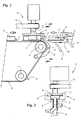
- a special feature of the device shown is a (first) turning device 18, which is arranged following the folding device 12 in the region of the conveying path 14 and serves to change the relative position of the partially folded packs 10.
- the partially folded packages 10 can be rotated so that they point forward during the subsequent transport along the conveying path 14 with another side surface in the transporting direction.
- the turning device 18 can also rotate the package 10 by other angles, for example 90 ° or 270 °. In this way, the package can be rotated so that, for example, has a side wall in the conveying direction.
- the turning device 18 Since the partially folded packs 10 are laid flat out of the folding device 12 and conveyed in this relative position along the straight-line conveying path 14, the turning device 18 is designed or arranged such that a rotation of the packs 10 about an upright axis takes place perpendicularly is directed to the plane of the conveying path 14. It is understood that the position of the axis of rotation of the turning device 18 can be adapted to the respective application.
- the turning device 18 has a receptacle 19 for partially folded packs 10.
- the receptacle 19 is designed in the manner of a pocket and offers space for a single partially folded pack 10.
- the cross section of the receptacle is adapted to the partially folded pack 10 such in that it is held in the partially folded position.
- the free cross section of the receptacle is bounded laterally, above and below by walls.
- the receptacle 19 is mounted on an upright shaft 20 which can be rotated by means of a drive belt 21 in rotation to change the relative position of the receptacle 19 located in the partially folded package 10.
- the receptacle 19 is rotated in each case partially folded package 10 by 180 ° in the same direction.
- the direction of rotation of the shaft 20 can also be reversed from pack 10 to pack 10, resulting in an alternating direction of rotation.
- the receptacle 19 is provided in cross-section on both sides with a slot 22 in which alternately enters a side flap of a partially folded package 10. Furthermore, the slot 22 also allows the handling of partially folded packages 10, in which another side tab projects or partially folded packages 10, which are fed in a different relative position.
- the transport of the partially folded packages 10 along the conveying path 14 takes place with the aid of a belt conveyor 23.
- the belt conveyor 23 is guided over deflection rollers 24.
- the belt conveyor 23 has radially projecting drivers 25.
- the partially folded packages 10 or partially finished packages 10 are transported in the region of an upper strand of the belt conveyor 23 between the folding device 12 and the drying device 16:
- the drivers 25 of the belt conveyor 23 serve to each detect a pack 10 in the conveying direction on the back and to transport along the conveying path 14.
- a bottom wall of the receptacle 19 has a slot 26 directed along the conveying path 14, through which the drivers 25 protrude into the receptacle 19 in order to respectively capture a pack 10 and to be transported out of the turning device 18 out.
- the belt conveyor 23 is driven continuously, so that the distance between the consecutive drivers 25 must be adapted to the transport speed of the belt conveyor 23 and the rotational speed of the turning device 18 that the rotation of a pack 10 is completed before the next driver 25th enters the receptacle 19.
- Another special feature relates to the arrangement of the upper strand of the belt conveyor 23 with respect to the turning device 18.
- the lateral extent of the upper run of the belt conveyor 23 is predetermined in the direction of the conveying path 14 by upper deflection rollers 24.
- the special feature is that in the region of the turning device 18, the corresponding deflection roller 24 is arranged directly below a feed opening 27 of the receptacle 19.
- the partially folded packages 10 are conveyed by means of a slide-in member 28 into the receptacle 19.
- the insertion member 28 is connected via a not shown gear along a Fig. 2 indicated movement path 29 out. In this way, it is ensured that the packs 10 in the pocket 13 of the folding device 12 are detected on the back and inserted in the plane of the conveying path 14 in the horizontal direction in the receptacle 19 of the turning device 18. Thereafter, the insertion member 28 is moved back opposite lowering it and subsequent increase in the starting position. This allows unimpeded rotation of the folding device 12 during the return of the insertion member 28th
- the insertion member 28 is adapted in terms of its shape to the outer diameter of the upper guide roller 24 in the region of the upper run of the belt conveyor 23, so that the insertion of the partially folded packages 10 is not disturbed by this guide roller 24.
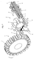
- the finished folded packages 10 are fed to the unit 15 of the drying device 16, which is formed in the present embodiment as a rotationally driven drying turret.
- the dry turret has pockets 30 which are arranged side by side at the periphery of the dry turret and are designed to receive a respective pack 10.
- the cross section of the pockets 30 is limited by walls 31.
- the dry turret serves to hold folding flaps of the package 10 in an overlapping position until the glue between the folding flaps has set sufficiently.
- the dry turret is designed such that the packs 10 have to be pushed into the pockets 30 counter to the original conveying direction.
- the coming of the unit 15 packs 10 are first transported with the bottom wall in the conveying direction on the dry turret and then inserted by means of a pack only shown 32 slide opposite to the original conveying direction in the region of a plug-in station in a pocket 30 of the dry turret.
- the pack 10 with the front wall in the new conveying direction is pushed into the pocket 30 until the end wall bears against a corresponding wall 31 of the pocket 30, so that the folding tabs 33, 34 form the end wall in this case , in the in Fig. 5 shown overlapping position are held until the glue 35 is set to connect the folding tabs 33, 34.
- a special feature is that the dry turret is coupled to the back of a central drive of the device, ie on the side remote from the folding device 12 of the dry turret. On this page is usually located within a housing of the central drive of the device or a corresponding transmission.
- the packs 10 are returned in the original conveying direction by a second packing pusher 36 in the region of a discharge station pushed out of the dry turret, ie pointing with the bottom wall in the conveying direction.
- the opening 49 is used to engage a portion of the packing slide 36 in the pocket 30.
- the cross-section of the opening 49 is smaller than the cross section of the pocket 30 so that a sufficient contact surface is present to the folding flaps of the pack 10 in the end wall properly in Overlap.
- the packs 10 are pushed out of the dry turret between parallel conveying runs 37, 38 of two belt conveyors 39, 40 and transported away at an angle, in particular transversely, to the original transport direction.
- the pockets 30 are arranged in the region of the Ausschubstation by an angle to the plane of the conveyor belt 37, 38 twisted.
- the packs 10 can therefore not be pushed easily between the conveyor belt 37, 38.
- the packages 10 are first supplied from the pockets 30 of the dry turret to a transfer device 48.
- the transfer device 48 is pivotable, such that the packs 10 are positioned between the delivery lanes 37, 38 and can be slid in a horizontal plane therebetween.
- the transfer device 48 is formed by a receptacle with two angled legs on which the packs 10 rest during the pivoting or turning operation.
- the packs 10 which are initially conveyed at a distance from one another, are dammed into a pack group 41 and subsequently transferred into a further turning device 42.
- the packs 10 or the pack group 41 are rotated by 180 °, so that the packs 10 are rotated back into the original relative position. Even with this rotation in the turning device 42, other rotation angle can be realized, according to the desired relative position for further transport.
- the turning device 42 is designed in the present case as a turning wheel, with receptacles 43 for each one pack group 41st
- the packing groups 41 are transferred via a bridge 44 to a further drying device 45, in the region of which the drying of the packs 10 is completed.
- a reciprocating slide 46 is used to transfer the packing groups 41 from the turning device 43 to the drying device 45.
- the pack groups 41 may be introduced into the dry turret 45 without rotation.
- the packing groups 41 are conveyed through the fixed turning device 42 and pushed away by means of another slide 47 transversely to the bridge 44, from which the packing group 41 is then in turn transferred by means of the slide 46 into the drying turret 45.
Landscapes
- Engineering & Computer Science (AREA)
- Mechanical Engineering (AREA)
- Wrapping Of Specific Fragile Articles (AREA)
Applications Claiming Priority (1)
| Application Number | Priority Date | Filing Date | Title |
|---|---|---|---|
| DE200810010433 DE102008010433A1 (de) | 2008-02-21 | 2008-02-21 | Verfahren und Vorrichtung zum Herstellen von Packungen für Zigaretten des Typs Klappschachtel |
Publications (2)
| Publication Number | Publication Date |
|---|---|
| EP2093146A1 true EP2093146A1 (fr) | 2009-08-26 |
| EP2093146B1 EP2093146B1 (fr) | 2012-05-30 |
Family
ID=40651330
Family Applications (1)
| Application Number | Title | Priority Date | Filing Date |
|---|---|---|---|
| EP20090000691 Ceased EP2093146B1 (fr) | 2008-02-21 | 2009-01-20 | Dispositif de fabrication d'emballages pour cigarettes de type boîte en carton à couvercle rabattable |
Country Status (2)
| Country | Link |
|---|---|
| EP (1) | EP2093146B1 (fr) |
| DE (1) | DE102008010433A1 (fr) |
Cited By (7)
| Publication number | Priority date | Publication date | Assignee | Title |
|---|---|---|---|---|
| CN103029859A (zh) * | 2011-08-22 | 2013-04-10 | 佛克有限及两合公司 | 生产用于香烟包装的设备和方法 |
| CN105346752A (zh) * | 2015-09-30 | 2016-02-24 | 白雪生 | 一种硬盒的条状内卡纸的包装方法 |
| EP3643625A1 (fr) | 2018-10-24 | 2020-04-29 | Focke & Co. (GmbH & Co. KG) | Procédé et dispositif de fabrication d'emballages pour produits de l'industrie de la cigarette |
| EP3643626A1 (fr) | 2018-10-24 | 2020-04-29 | Focke & Co. (GmbH & Co. KG) | Procédé et dispositif de fabrication d'emballages pour produits de l'industrie de la cigarette |
| CN111846393A (zh) * | 2020-08-13 | 2020-10-30 | 贵州鑫淼科技有限公司 | 一种用于ch烟包透明纸包装机的烟包九十度翻转机 |
| CN111924198A (zh) * | 2020-09-11 | 2020-11-13 | 湖南中南高创烟草科技有限公司 | 烟支烟盒填装条盒的设备及方法 |
| CN114987819A (zh) * | 2022-06-28 | 2022-09-02 | 四川中烟工业有限责任公司 | 一种小型纸盒的自动装填系统及方法 |
Families Citing this family (4)
| Publication number | Priority date | Publication date | Assignee | Title |
|---|---|---|---|---|
| DE102008027258A1 (de) | 2008-06-06 | 2009-12-10 | Focke & Co.(Gmbh & Co. Kg) | Verfahren und Vorrichtung zum Herstellen von Zigarettenpackungen |
| DE102013009472A1 (de) * | 2013-06-06 | 2014-12-11 | Focke & Co. (Gmbh & Co. Kg) | Verfahren und Vorrichtung zum Herstellen von Zigarettenpackungen |
| DE102017011309A1 (de) | 2017-12-08 | 2019-06-13 | Focke & Co. (Gmbh & Co. Kg) | Verpackungsmaschine zum Herstellen von Zigarettenpackungen |
| DE102017011310A1 (de) * | 2017-12-08 | 2019-06-13 | Focke & Co. (Gmbh & Co. Kg) | Verpackungsmaschine zum Herstellen von Zigarettenpackungen |
Citations (8)
| Publication number | Priority date | Publication date | Assignee | Title |
|---|---|---|---|---|
| US2370325A (en) * | 1944-01-12 | 1945-02-27 | Wm Wrigley Jr | Package turnover apparatus |
| US4086744A (en) | 1974-04-17 | 1978-05-02 | G. D. Societa Per Azioni | Device for preparing hinge-lid packets of cigarettes for application of sealing strips and the like |
| EP0313938A1 (fr) * | 1987-10-28 | 1989-05-03 | Focke & Co. (GmbH & Co.) | Dispositif de stabilisation et de séchage des paquets en forme de parallélépipède rectangle |
| EP0243757B1 (fr) * | 1984-01-11 | 1992-04-22 | Focke & Co. (GmbH & Co.) | Machine d'emballage pour emballages avec volets de pliage reliés par collage |
| EP0492123A1 (fr) | 1990-12-22 | 1992-07-01 | Focke & Co. (GmbH & Co.) | Machine de fabrication de boîtes à charnière |
| EP0741081A2 (fr) | 1995-05-05 | 1996-11-06 | G.D Societa' Per Azioni | Machine et procédé d'emballage de produits ayant des moyens pour sécher les paquets ainsi obtenus |
| EP1359092A1 (fr) * | 2002-05-03 | 2003-11-05 | G.D Societ Per Azioni | Procédé et dispositif pour faire basculer des piles d' objets dans une machine d' encartonnage |
| EP1862387A2 (fr) * | 2006-05-30 | 2007-12-05 | G.D Societ Per Azioni | Procédé d'emballage et machine pour produire des paquets de cigarettes |
Family Cites Families (5)
| Publication number | Priority date | Publication date | Assignee | Title |
|---|---|---|---|---|
| DE2715121A1 (de) * | 1977-04-05 | 1978-10-19 | Hauni Werke Koerber & Co Kg | Wendevorrichtung fuer eine packmaschine zum verpacken von stabfoermigen artikeln der tabakverarbeitenden industrie |
| DE3915246A1 (de) * | 1989-05-10 | 1990-11-15 | Focke & Co | Verfahren und foerdervorrichtung zur foerderung von gegenstaenden |
| IT1286773B1 (it) * | 1996-11-18 | 1998-07-17 | Gd Spa | Metodo di incarto per pacchetti rigidi di sigarette |
| DE19847433A1 (de) * | 1998-10-15 | 2000-04-20 | Focke & Co | Vorrichtung zur Erzeugung hin- und hergehender Bewegungen |
| DE102006021991A1 (de) * | 2006-05-10 | 2007-11-15 | Focke & Co.(Gmbh & Co. Kg) | Klappschachtel für Zigaretten sowie Verfahren und Vorrichtung zum Herstellen derselben |
-
2008
- 2008-02-21 DE DE200810010433 patent/DE102008010433A1/de not_active Withdrawn
-
2009
- 2009-01-20 EP EP20090000691 patent/EP2093146B1/fr not_active Ceased
Patent Citations (8)
| Publication number | Priority date | Publication date | Assignee | Title |
|---|---|---|---|---|
| US2370325A (en) * | 1944-01-12 | 1945-02-27 | Wm Wrigley Jr | Package turnover apparatus |
| US4086744A (en) | 1974-04-17 | 1978-05-02 | G. D. Societa Per Azioni | Device for preparing hinge-lid packets of cigarettes for application of sealing strips and the like |
| EP0243757B1 (fr) * | 1984-01-11 | 1992-04-22 | Focke & Co. (GmbH & Co.) | Machine d'emballage pour emballages avec volets de pliage reliés par collage |
| EP0313938A1 (fr) * | 1987-10-28 | 1989-05-03 | Focke & Co. (GmbH & Co.) | Dispositif de stabilisation et de séchage des paquets en forme de parallélépipède rectangle |
| EP0492123A1 (fr) | 1990-12-22 | 1992-07-01 | Focke & Co. (GmbH & Co.) | Machine de fabrication de boîtes à charnière |
| EP0741081A2 (fr) | 1995-05-05 | 1996-11-06 | G.D Societa' Per Azioni | Machine et procédé d'emballage de produits ayant des moyens pour sécher les paquets ainsi obtenus |
| EP1359092A1 (fr) * | 2002-05-03 | 2003-11-05 | G.D Societ Per Azioni | Procédé et dispositif pour faire basculer des piles d' objets dans une machine d' encartonnage |
| EP1862387A2 (fr) * | 2006-05-30 | 2007-12-05 | G.D Societ Per Azioni | Procédé d'emballage et machine pour produire des paquets de cigarettes |
Cited By (10)
| Publication number | Priority date | Publication date | Assignee | Title |
|---|---|---|---|---|
| CN103029859A (zh) * | 2011-08-22 | 2013-04-10 | 佛克有限及两合公司 | 生产用于香烟包装的设备和方法 |
| CN103029859B (zh) * | 2011-08-22 | 2016-03-02 | 佛克有限及两合公司 | 生产用于香烟包装的设备 |
| CN105346752A (zh) * | 2015-09-30 | 2016-02-24 | 白雪生 | 一种硬盒的条状内卡纸的包装方法 |
| CN105346752B (zh) * | 2015-09-30 | 2017-10-10 | 白雪生 | 一种硬盒的条状内卡纸的包装方法 |
| EP3643625A1 (fr) | 2018-10-24 | 2020-04-29 | Focke & Co. (GmbH & Co. KG) | Procédé et dispositif de fabrication d'emballages pour produits de l'industrie de la cigarette |
| EP3643626A1 (fr) | 2018-10-24 | 2020-04-29 | Focke & Co. (GmbH & Co. KG) | Procédé et dispositif de fabrication d'emballages pour produits de l'industrie de la cigarette |
| CN111846393A (zh) * | 2020-08-13 | 2020-10-30 | 贵州鑫淼科技有限公司 | 一种用于ch烟包透明纸包装机的烟包九十度翻转机 |
| CN111924198A (zh) * | 2020-09-11 | 2020-11-13 | 湖南中南高创烟草科技有限公司 | 烟支烟盒填装条盒的设备及方法 |
| CN114987819A (zh) * | 2022-06-28 | 2022-09-02 | 四川中烟工业有限责任公司 | 一种小型纸盒的自动装填系统及方法 |
| CN114987819B (zh) * | 2022-06-28 | 2024-04-16 | 四川中烟工业有限责任公司 | 一种小型纸盒的自动装填系统及方法 |
Also Published As
| Publication number | Publication date |
|---|---|
| DE102008010433A1 (de) | 2009-08-27 |
| EP2093146B1 (fr) | 2012-05-30 |
Similar Documents
| Publication | Publication Date | Title |
|---|---|---|
| EP2093146B1 (fr) | Dispositif de fabrication d'emballages pour cigarettes de type boîte en carton à couvercle rabattable | |
| EP2303702B1 (fr) | Procede et dispositif de production d'emballages | |
| EP0878398B1 (fr) | Procédé et dispositif pour plier le rabat terminal d'un flan pour une boíte à cigarettes | |
| EP1829783B1 (fr) | Dispositif et procédé de fabrication d'emballages doubles | |
| DE102017201830A1 (de) | Faltvorrichtung, Verpackungsanlage für Artikel und Verfahren zum Falten von Seitenlaschen von Kartonumverpackungen | |
| WO2008101571A1 (fr) | Emballage pour cigarettes et procédé et dispositif de fabrication d'emballages | |
| DE2755071A1 (de) | Etikettiermaschine | |
| EP2234891A2 (fr) | Procédé et dispositif de fabrication d'emballages pour cigarettes | |
| EP1601575B1 (fr) | Procede et dispositif pour produire des emballages d'au moins deux paquets | |
| EP2562092A1 (fr) | Dispositif et procédé de fabrication d'emballages pour cigarettes | |
| EP2709912B1 (fr) | Procédé et dispositif de fabrication d'emballages du type boîte à rabat pour cigarettes | |
| EP0268917B1 (fr) | Machine d'emballage, spécialement pour paquets de cigarettes | |
| DE3421261A1 (de) | Vorrichtung zum falten und verschliessen der stirnwaende von tray-kartons | |
| EP2076377A1 (fr) | Procédé et dispositif de production d'emballages (de cigarettes) | |
| EP3385175A1 (fr) | Dispositif de fermeture de boite pliante | |
| EP2746166B1 (fr) | Procédé et dispositif de fabrication d'un emballage pour cigarettes | |
| DE10203459A1 (de) | Verfahren und Vorrichtung zum Herstellen von Gebindepackung für Zigaretten | |
| DE102014000398A1 (de) | Verpackungsmaschine und Verpackungsverfahren zum Herstellen einer starren Verpackung von Tabakartikeln | |
| EP3643626B1 (fr) | Procédé et dispositif de fabrication d'emballages pour produits de l'industrie de la cigarette | |
| EP3676185B1 (fr) | Dispositif et procédé de fabrication de paquets de cigarettes | |
| WO2015090484A1 (fr) | Procédé et dispositif servant à produire un emballage pour des produits de l'industrie de la cigarette | |
| DE1277104B (de) | Vorrichtung zum Einfalten der Verschlusslaschen von Faltkartons | |
| DE19901238B4 (de) | Vorrichtung zum Fördern eines vorgefalteten Verpackungszuschnittes in einer Verpackungsmaschine | |
| EP1567417B1 (fr) | Procede et dispositif permettant la mise en forme de pieces decoupees en carton | |
| DE19901237B4 (de) | Verfahren zum Aufrichten einer Faltschachtel aus einem einteiligen Kartonzuschnitt |
Legal Events
| Date | Code | Title | Description |
|---|---|---|---|
| PUAI | Public reference made under article 153(3) epc to a published international application that has entered the european phase |
Free format text: ORIGINAL CODE: 0009012 |
|
| AK | Designated contracting states |
Kind code of ref document: A1 Designated state(s): AT BE BG CH CY CZ DE DK EE ES FI FR GB GR HR HU IE IS IT LI LT LU LV MC MK MT NL NO PL PT RO SE SI SK TR |
|
| AX | Request for extension of the european patent |
Extension state: AL BA RS |
|
| 17P | Request for examination filed |
Effective date: 20100204 |
|
| 17Q | First examination report despatched |
Effective date: 20100305 |
|
| AKX | Designation fees paid |
Designated state(s): DE GB IT |
|
| GRAP | Despatch of communication of intention to grant a patent |
Free format text: ORIGINAL CODE: EPIDOSNIGR1 |
|
| RTI1 | Title (correction) |
Free format text: DEVICE FOR THE MANUFACTURE OF FLIP PACK CIGARETTE PACKETS |
|
| GRAS | Grant fee paid |
Free format text: ORIGINAL CODE: EPIDOSNIGR3 |
|
| GRAA | (expected) grant |
Free format text: ORIGINAL CODE: 0009210 |
|
| AK | Designated contracting states |
Kind code of ref document: B1 Designated state(s): DE GB IT |
|
| REG | Reference to a national code |
Ref country code: GB Ref legal event code: FG4D Free format text: NOT ENGLISH |
|
| REG | Reference to a national code |
Ref country code: DE Ref legal event code: R096 Ref document number: 502009003632 Country of ref document: DE Effective date: 20120726 |
|
| PLBE | No opposition filed within time limit |
Free format text: ORIGINAL CODE: 0009261 |
|
| STAA | Information on the status of an ep patent application or granted ep patent |
Free format text: STATUS: NO OPPOSITION FILED WITHIN TIME LIMIT |
|
| 26N | No opposition filed |
Effective date: 20130301 |
|
| REG | Reference to a national code |
Ref country code: DE Ref legal event code: R097 Ref document number: 502009003632 Country of ref document: DE Effective date: 20130301 |
|
| PGFP | Annual fee paid to national office [announced via postgrant information from national office to epo] |
Ref country code: DE Payment date: 20191220 Year of fee payment: 12 Ref country code: IT Payment date: 20200114 Year of fee payment: 12 Ref country code: GB Payment date: 20200113 Year of fee payment: 12 |
|
| REG | Reference to a national code |
Ref country code: DE Ref legal event code: R119 Ref document number: 502009003632 Country of ref document: DE |
|
| GBPC | Gb: european patent ceased through non-payment of renewal fee |
Effective date: 20210120 |
|
| PG25 | Lapsed in a contracting state [announced via postgrant information from national office to epo] |
Ref country code: GB Free format text: LAPSE BECAUSE OF NON-PAYMENT OF DUE FEES Effective date: 20210120 Ref country code: DE Free format text: LAPSE BECAUSE OF NON-PAYMENT OF DUE FEES Effective date: 20210803 |
|
| PG25 | Lapsed in a contracting state [announced via postgrant information from national office to epo] |
Ref country code: IT Free format text: LAPSE BECAUSE OF NON-PAYMENT OF DUE FEES Effective date: 20210120 |