EP1567417B1 - Procede et dispositif permettant la mise en forme de pieces decoupees en carton - Google Patents
Procede et dispositif permettant la mise en forme de pieces decoupees en carton Download PDFInfo
- Publication number
- EP1567417B1 EP1567417B1 EP03789083A EP03789083A EP1567417B1 EP 1567417 B1 EP1567417 B1 EP 1567417B1 EP 03789083 A EP03789083 A EP 03789083A EP 03789083 A EP03789083 A EP 03789083A EP 1567417 B1 EP1567417 B1 EP 1567417B1
- Authority
- EP
- European Patent Office
- Prior art keywords
- forming
- blanks
- shaft
- previous
- forming shaft
- Prior art date
- Legal status (The legal status is an assumption and is not a legal conclusion. Google has not performed a legal analysis and makes no representation as to the accuracy of the status listed.)
- Expired - Lifetime
Links
- 238000000034 method Methods 0.000 title claims abstract description 20
- 239000011087 paperboard Substances 0.000 title abstract description 3
- 239000000969 carrier Substances 0.000 claims description 2
- 238000007493 shaping process Methods 0.000 description 10
- 230000005540 biological transmission Effects 0.000 description 3
- 210000000056 organ Anatomy 0.000 description 3
- 239000003292 glue Substances 0.000 description 2
- 238000007373 indentation Methods 0.000 description 2
- 238000000465 moulding Methods 0.000 description 2
- 125000004122 cyclic group Chemical group 0.000 description 1
- 230000001419 dependent effect Effects 0.000 description 1
- 238000011161 development Methods 0.000 description 1
- 230000018109 developmental process Effects 0.000 description 1
- 238000005553 drilling Methods 0.000 description 1
- 238000004806 packaging method and process Methods 0.000 description 1
- 239000000123 paper Substances 0.000 description 1
- 230000000284 resting effect Effects 0.000 description 1
- 230000002123 temporal effect Effects 0.000 description 1
Images

Classifications
-
- B—PERFORMING OPERATIONS; TRANSPORTING
- B65—CONVEYING; PACKING; STORING; HANDLING THIN OR FILAMENTARY MATERIAL
- B65B—MACHINES, APPARATUS OR DEVICES FOR, OR METHODS OF, PACKAGING ARTICLES OR MATERIALS; UNPACKING
- B65B43/00—Forming, feeding, opening or setting-up containers or receptacles in association with packaging
- B65B43/08—Forming three-dimensional containers from sheet material
- B65B43/10—Forming three-dimensional containers from sheet material by folding the material
-
- B—PERFORMING OPERATIONS; TRANSPORTING
- B31—MAKING ARTICLES OF PAPER, CARDBOARD OR MATERIAL WORKED IN A MANNER ANALOGOUS TO PAPER; WORKING PAPER, CARDBOARD OR MATERIAL WORKED IN A MANNER ANALOGOUS TO PAPER
- B31B—MAKING CONTAINERS OF PAPER, CARDBOARD OR MATERIAL WORKED IN A MANNER ANALOGOUS TO PAPER
- B31B50/00—Making rigid or semi-rigid containers, e.g. boxes or cartons
- B31B50/26—Folding sheets, blanks or webs
- B31B50/44—Folding sheets, blanks or webs by plungers moving through folding dies
Definitions
- the invention relates to a method for erecting (flat) blanks for cartons, cartons, trays or the like, wherein the blanks moved in front of an opening of a mold shaft and pressed with a, in particular movable up and down, forming die in the mold shaft, under erection of Parts of the blank, in particular in the region of longitudinal walls and / or transverse walls of the carton or the like. Furthermore, the invention relates to a corresponding device.
- a blank is moved in front of the opening of a mold shaft and pressed by the forming die into the mold shaft, wherein parts of the blank are erected or folded. Subsequently, the forming die is pulled out of the mold shaft and moves the next blank in front of the opening of the mold shaft, whereupon the entire process is repeated. See eg GB 1.103.189.
- the invention has the object of further developing a method and an apparatus of the type mentioned, in particular to propose measures that lead to an increase in the operating speed.
- the method according to the invention is characterized in that the molding die is moved back after pressing a blank in the mold shaft at least partially outside of the mold shaft in a position in front of the opening of the mold shaft.
- the forming dies are thereby moved out of the mold shaft contrary to the indentation direction of the blanks, in particular swung out.
- the forming punch is thus not moved back through the opening, but at least in a (part) area out of the mold shaft. In this way, the next blank to be erected even before the opening of the Shaping shaft moves, in particular promoted before the forming die has reached its starting position in front of the opening of the forming shaft.
- the forming shaft are associated with at least two forming dies, which are successively moved to impress each one (single) blank in the forming shaft.
- the operating speed of the device can be doubled, while maintaining the speed of the forming die.
- two forming dies are provided, which are operated offset in time from one another such that a second forming punch presses a blank through the opening of the forming chute when a first forming punch has substantially completed the erection of another blank, in particular this blank a subsidy to. Removal of at least partially erected blanks transfers.
- the blanks are fed continuously and the forming dies are driven continuously, so that loads on the device can be avoided by a cyclic operation.
- An apparatus for solving the above-mentioned problem has the features of claim 10.
- at least two forming dies are also provided, which are successively movable through the forming shaft.
- the forming dies can be rotatable, in particular pivotable, mounted on respective carriages or carriages which can be moved up and down outside the forming shaft and are preferably moved by a respective continuously driven belt.
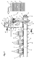
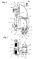
- FIGS. 1 to 7 show parts of a device for cartoning products 10.
- the products 10 are packed in so-called trays 11. At the location of the tray 11 shown but also any other (pack) packs can be used, such as boxes, cartons or the like.
- the trays 11 are made from substantially flat blanks 12 of paper, (corrugated) paperboard, plastic or the like.
- the blanks 12 are removed from a blank stack 13.
- the individual blanks 12 lie flat in the blank stack 13, preferably with a substantially horizontal extent.
- the blank stack 13 may also be in be arranged a blank magazine from which the individual blanks 12 are conveyed out or removed.
- the blanks 12 are fed to a Aufrichtstation 14.
- the substantially flat blanks 12 are prepared by erecting parts of the blank 12, for example by folding up longitudinal walls or transverse walls for receiving the products 10.
- a part of the upright side walls 15 of the tray 11 is formed in the erecting station 14.
- further side walls, in particular all side walls can be erected in the erection station 14.
- the blanks 12 are conveyed individually in front of an opening 16 of a forming shaft 17 of the erecting station 14.
- the opening 16 is delimited by at least two walls of the mold shaft 17, which are arranged opposite one another and are arranged substantially vertically in a lower region and preferably run flat.
- the side walls 19 are widened in a funnel shape, preferably with a circular radius in the region of the widening. Subsequently, the side walls extend approximately horizontally as a bearing surface for the blanks 12.
- Two other side walls of the rectangular shape in the planer shaft 17 are open, so as not to interfere with the path of movement of the forming punch 20.
- the size of the opening 16 is dimensioned such that the blank 12 rests on the funnel-shaped side walls 19 in the region of two opposite edges. Transverse thereto, the blank 12 has a dimension, for example, a width which is less than the inside width of the forming shaft 17th
- the blanks 12 are each individually pressed by a forming die 20 into the forming chute 17, under erection of parts of the blank 12 by abutment in the region of the funnel-shaped narrowing in the conveying direction side walls 19 of the forming chute 17.
- the die 20 is aligned approximately horizontally.
- the partially folded or erected blanks 12 are conveyed downwards by the forming punch 20 in the forming chute 17 in an approximately vertical direction and are transferred directly to a conveying means 21 extending underneath the forming chute 17 which removes the partially folded blanks 12 from the area of the forming chute 17.
- a first peculiarity of Aufrichtstation 14 is the return of the forming die 20 in front of the opening 16 of the mold shaft 17 after pressing a blank 12 in the mold shaft 17.
- the shaping punches 20, 22 are successively moved through the forming shaft 17, each forming punch 20, 22 each pressing a single blank 12 into the forming shaft 17.
- the shaping punches 20, 22 are arranged such that they are moved with (temporal and spatial) distance from one another through the forming shaft 17.
- the other forming die 20 is pivoted about the opening 16 at about this time for impressing the subsequent blank 12th In this way, a doubling of the clock rate is achieved in the case shown.
- the distance of the successive forming dies 20, 22 is dimensioned such that a sufficient space for moving out of the lower punch 20, 22 is available.
- more than two forming dies 20, 22 may be provided.
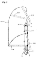
- the forming dies 20, 22 are moved out of the forming shaft 17 (FIG. 3).
- the forming dies 20, 22 are first pivoted about a pivot point 23 in an approximately vertical orientation and thereby moved out of the mold shaft 17.
- the pivoting of the dies 20, 22 takes place counter to the Eindschreibraum the blanks 12.
- the forming dies 20, 22 are moved upward, wherein the vertical alignment of the forming dies 20, 22 is maintained. In an upper end position, the forming punches 20, 22 are pivoted back into an approximately horizontal position in front of the opening 16 of the forming shaft 17.
- Fig. 3 shows this sequence of movements schematically for the forming die 22 shown in FIG.
- the forming punch 20 is moved in an analogous manner.
- the movement sequence of the forming punch 20 can be seen in mirror image to the movement sequence of the forming punch 22 shown in FIG. 3, since the two forming punches 20, 22 are arranged opposite one another on the forming chute 17. Furthermore, it is possible to superimpose the movement of the forming dies 20, 22 in the vertical direction with the pivoting or rotating movement.
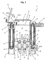
- the two forming dies 20, 22 are each driven by an endless conveyor.
- a drive motor 24 drives via a drive shaft 25, two toothed belts 26 as endless conveyors, which are arranged in a vertical direction on both sides of the forming shaft 17 and each of which a forming die 20, 22 is assigned.
- the drive shaft 25 is coupled in each case with an upper gear 27, which drives the toothed belt 26.
- the direction of movement of the toothed belt 26 is opposite, as indicated by arrows in Fig. 2.
- lower gears 28 are provided, over which the toothed belts 26 are guided.
- each shaping die 20, 22 is assigned its own toothed belt 26.
- the forming dies 20, 22 lying on the same side of the forming chute 17 can preferably be driven by a common toothed belt 26.
- the toothed belts 26 are each coupled to a driver 29.
- the drivers 29 are coupled in the region of a lateral free end 30 with the toothed belt 26.
- the adjacent free lateral end 30 of the driver 29 is also movably mounted in an oval curve trace 31, namely via an annular bearing bush 32.
- the curve trace 31 is formed as a recess in a bearing block 33, which is otherwise substantially rectangular in plan. This bearing block 33 extends at least over the entire height of the toothed belt 26.
- Another opposite lateral end 34 of the driver 29 extends through a bore 35 in the dies 20, 22.
- the forming dies 20, 22 in Area of a lateral free end of the carriers 29 stored.
- the advantageous movement path 37 of the forming dies 20, 22 as shown schematically in Fig. 3.
- the shaping punches 22 are approximately L-shaped in cross-section with a first longer leg 38 and a second shorter leg 39.
- the shorter leg 39 is also angled or cranked.
- the longer legs 38 of the forming punches 20, 22 in the plan are partially rectangular or square.
- these have a central recess 40.
- the attachment of the forming dies 20, 22 to the drivers 29 is, as already described, arranged in the region of a lateral end of the forming dies 20, 22, namely in the vicinity of the bent portion.
- the second pivot point 23 is also formed.
- the forming dies 20, 22 are rotatably mounted on an axle 41, which in turn cantilevered on a movable up and down slide 42 is mounted.
- the carriage 42 is movably mounted on two guide rails 43 in an exclusively vertical direction.
- the guide rails 43 are associated with the bearing blocks 33 and extend on both sides of the toothed belt 26.
- the guide rails 43, the path of movement of the axis 41 and the pivot point 23 is predetermined. This is therefore only movable in the vertical direction, namely up or down.
- the conveying path of the blanks in the forming shaft 17 is followed by a laterally directed transport of the partially folded blanks 12.
- the conveyor 21 is provided.
- the conveying means 21 are preferably one or more parallel (endless) conveyor belts 45, which are driven by deflection rollers 46.
- the conveyor belt (s) 45 may be disposed below the mold cavity 17 or may extend partially therethrough.
- two parallel conveyor belts 45 are provided as an endless conveyor, the deflection rollers 46 are arranged on a common axis 47.
- the partially folded blanks 12 are deposited on the conveyor belts 45 by the shaping punches 20, 22, namely exactly between drivers 48, which are arranged on the outside of the conveyor belts 45.
- the drivers 48 are each arranged in pairs, wherein the mutually facing upright side surfaces of the paired drivers 48 are provided with a chamfer. The space between the pairs of drivers 48 is thereby extended upward.
- the minimum distance of the paired driver 48 corresponds approximately to the corresponding cross-sectional dimension of the trays 11.
- the partially folded blanks 12 are conveyed out of the Aufrichtstation 14 side.
- further side walls are erected or folded upwards and connected to the already erected side walls 15, for example by applying glue.
- the erection of the remaining side walls and bonding with the folded in the Aufrichtstation 14 side walls 15 is preferably carried out after the products 11 were deposited from above on or in the partially folded blank 12.
- the erection or folding up of the remaining side walls can be done with the help of special Folding organs or folding rails done.
- the glue is preferably applied in the region of folding tabs 49.
- the described device or the method for erecting the blanks 12 is preferably carried out completely continuously. This also applies to the feeding of the blanks 12 from the blank stack 13 and the lateral removal of the partially folded blanks 12 on the conveyor 21st
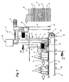
- FIGS. 5 to 7 show a second, preferred exemplary embodiment. If the following described organs of this device functionally correspond to the organs described in the first exemplary embodiment, matching designations or reference symbols are used.
- the device shown in the second embodiment differs from the embodiment of FIGS. 1 to 4 only in terms of the structural design of the erection station 14, namely with respect to the means provided for carrying out the movement of the forming dies 20, 22 means.
- the pushing-in movement of the forming punches 20, 22 and the removal of the same from the forming shaft 17 is essentially identical to the first embodiment.
- the blanks 12 are removed individually from a blank stack 13 and moved in front of the opening 16 of a mold shaft 17. There, the individual blanks 12 are detected by a forming die 20, 22 on the upper side and pressed into the mold shaft 17, wherein the blank 12 is at least partially erected.
- an endless conveyor of two parallel conveyor belts 45 is arranged below the mold shaft 17 as in the first embodiment. Individual blanks 12 are deposited by the forming dies 20, 22 between drivers 48 at the top of the conveyor belts 45.
- the conveyor 21 formed by the conveyor belts 45 is designed as a preferably continuously operated endless conveyor and serves for The folding out or erecting of the blanks 12 is completed as in the first exemplary embodiment during further lateral or horizontal transport on the conveyor 21.
- two forming dies 20, 22 are provided.
- the shaping punches 20, 22 are arranged here in plan view on the same side of the molding shaft 17.
- the forming punches 20, 22 are each pivotally mounted on a carriage 50 which is movable along a linear axis 51.
- the linear axes 51 are arranged substantially vertically aligned in the illustrated embodiment, so that the forming dies 20, 22 along the linear axes 51 in the vertical direction can be moved up or down.
- the carriage 50 is in each case associated with a servomotor 52, which allows a pivoting of the mounted on the carriage 50 forming dies 20, 22 about a pivot point 23.
- the forming dies 20, 22 are successively pivoted one after the other on the upper side for abutment against a blank 12 lying flat on the side walls 19 of the forming shaft 17.
- the carriages 50 By moving the carriages 50 downwards in a substantially vertical direction, the blanks 12 are individually pressed into the forming shaft 17 with at least partial erection of the blanks 12.
- the forming punches 20, 22 are aligned approximately horizontally. In a lower end position of the carriages 50, the blanks 12 are transferred to the conveying means 21 by the shaping punches 20, 22.
- the forming dies 20, 22 are pivoted out of the forming shaft 17 counter to the indentation direction about the pivot point 23 into an upright, substantially vertical position. Thereafter, the carriages 50 are moved upward to an upper end position, wherein the substantially vertical alignment of the forming dies 20, 22 is maintained. Finally, the dies 20, 22 are pivoted in the direction of depression in the approximately horizontal position in which the dies 20, 22 at the level of the opening 16 of the mold shaft 17 on the upper side abut the blanks 12.
- the shaping punches 20, 22 are moved through the forming shaft 17 in a temporally and spatially displaced manner, so that, after pivoting back a lower forming punch 22, the upper forming punch 20 can be moved into the forming shaft 17 with a blank 12.
- the returning of the forming dies 20, 22 into an upper starting position can thus take place while the respective other forming punch 20, 22 is already moved through the forming chute 17.
- a doubling of the clock rate is achieved as in the first embodiment.
- the pivoting back of the forming dies 20, 22 takes place as in the first embodiment against the Eindrückraum the blanks.
- the moving back of the forming dies 20, 22 in front of the opening 16 as in the first embodiment substantially outside of the mold shaft 17.
- the pivoting movement can be superimposed with the up and / or downward movement.
- the linear axes 51 each include endless conveyors, for example continuously driven, circulating toothed belts, straps or the like, each of which is guided over a lower deflection roller 53 and an upper, common transmission shaft 54.
- the two circulating conveyor belts in the linear axes 51 are driven by a common servo motor 55, which is coupled to the transmission shaft 54.
- the opposite movement of the two forming dies 20, 22 results from the respective arrangement of the carriages 50 on opposite conveying paths of the respective endless conveyors of the linear axes 51.
- the carriage 50 associated with the forming die 20 is attached to a the forming shaft 17 facing conveying strand arranged, whereas the forming die 22 associated carriage 50 is disposed on a side facing away from the forming shaft 17 conveying strand of the linear axis 51 (Fig. 7).
- the two linear axes are arranged in plan on the same side of the conveyor belts 45 of the conveyor 21.
- a linear axis 51 is arranged approximately at the level of the forming shaft 17, wherein the second linear axis 51, which moves the forming punch 20 in the embodiment shown, is arranged laterally offset from the forming shaft 17.
- arms 56, 57 which connect the forming dies 20, 22 in each case to the corresponding slide 50 are angled or cranked.
- the arms 56, 57 each formed in plan and in the side view double angled, for bridging the distance between the linear axes 51 and the mold shaft 17th
Abstract
Claims (19)
- Procédé de mise en forme de pièces découpées plates (12) pour cartons, boîtes pliantes, plateaux (11) ou similaires, les pièces découpées (12) étant déplacées devant une ouverture (16) d'une boîte façonnée (17) et enfoncées dans la boîte façonnée (17) par un poinçon de façonnage (20, 22) pouvant notamment monter et descendre, en mettant en forme les parties de la pièce découpée (12), notamment dans la zone des parois latérales (15) et/ou des parois longitudinales et/ou des parois transversales du carton ou similaire, caractérisé en ce que le poinçon de façonnage (20, 22), après avoir enfoncé une pièce découpée (12) dans la boîte façonnée (17), est redéplacé dans le sens inverse de la direction d'enfoncement des pièces découpées (12) et au moins en partie.à l'extérieur de la boîte façonnée (17) dans une position située devant l'ouverture (16) de la boîte façonnée (17).
- Procédé selon la revendication 1, caractérisé en ce qu'au moins deux poinçons de façonnage (20, 22), qui sont déplacés successivement pour enfoncer respectivement une pièce découpée (12) individuelle dans la boîte façonnée (17), sont associés à la boîte façonnée (17).
- Procédé selon la revendication 2, caractérisé en ce que les poinçons de façonnage (20, 22) sortent en pivotant de la boîte façonnée (17).
- Procédé selon l'une quelconque des revendications précédentes, caractérisé en ce que les poinçons de façonnage (20, 22) sont déplacés, notamment amenés à pivoter à l'extérieur de la boîte façonnée (17) devant son ouverture (16), pour enfoncer une autre pièce découpée (12).
- Procédé selon l'une quelconque des revendications précédentes, caractérisé en ce que les poinçons de façonnage (20, 22) sont entraînés de manière continue, notamment par un entraînement commun (24, 55).
- Procédé selon l'une quelconque des revendications précédentes, caractérisé en ce que les pièces découpées (12) sont prélevées d'une pile de pièces découpées (13), notamment d'un chargeur de pièces découpées, et acheminées devant l'ouverture (16) de la boîte façonnée (17).
- Procédé selon l'une quelconque des revendications précédentes, caractérisé en ce que les pièces découpées (12) au moins en partie mises en forme, sont amenées immédiatement après la boîte façonnée (17) à un moyen de transport (21), notamment un convoyeur sans fin fonctionnant en continu comprenant au moins une courroie de transport (45).
- Procédé selon l'une quelconque des revendications précédentes, caractérisé en ce que les pièces découpées (12) sont amenées par les poinçons de façonnage (20, 22) au moyen de transport (21), notamment dans des poches du moyen de transport (21), et/ou sont pressées entre des éléments d'entraînement (48) fixés sur le moyen de transport (21).
- Procédé selon l'une quelconque des revendications précédentes, caractérisé en ce que la mise en forme des pièces découpées (12) est achevée pendant le transport sur le moyen de transport (21), notamment après avoir déposé les produits (10) dans les cartons, boîtes pliantes, plateaux (11) ou similaires en partie terminé(e)s.
- Dispositif pour le procédé de mise en forme de pièces découpées (plates) (12) pour cartons, boîtes pliantes, plateaux (11) ou similaires, les pièces découpées (12) pouvant être déplacées devant une ouverture (16) d'une boîte façonnée (17) et pouvant être enfoncées dans la boîte façonnée (17) par un poinçon de façonnage (20, 22) pouvant notamment monter et descendre, en mettant en forme des parties de la pièce découpée (12), notamment dans la zone des parois latérales (15) et/ou des parois longitudinales et/ou des parois transversales du carton ou similaire, caractérisé en ce que le poinçon de façonnage (20, 22), après avoir enfoncé une pièce découpée (12) dans la boîte façonnée (17), est redéplacé au moins en partie à l'extérieur de la boîte façonnée (17) dans une position située devant l'ouverture (16) de la boîte façonnée (17), le poinçon de façonnage (20, 22) sortant de la boîte façonnée (17) dans le sens inverse de la direction d'enfoncement des pièces découpées (12).
- Procédé selon la revendication 10, caractérisé en ce qu'au moins deux poinçons de façonnage (20, 22), qui peuvent être déplacés successivement pour enfoncer respectivement une pièce découpée (12) individuelle à travers la boîte façonnée (17), sont associés à la boîte façonnée (17).
- Dispositif selon l'une quelconque des revendications précédentes, caractérisé en ce que les poinçons de façonnage (20, 22) sont montés à rotation, notamment à pivotement, pour sortir en pivotant de la boîte façonnée (17) et/ou pour entrer en pivotant devant l'ouverture (16) de la boîte façonnée (17).
- Dispositif selon l'une quelconque des revendications précédentes, caractérisé en ce que les poinçons de façonnage (20, 22) sont montés à rotation, notamment à pivotement sur respectivement un chariot (42) ou coulisseau (50) pouvant monter et descendre à l'extérieur de la boîte façonnée (17).
- Dispositif selon l'une quelconque des revendications précédentes, caractérisé en ce qu'un moyen de transport (21), notamment un convoyeur sans fin, est disposé immédiatement après la boîte façonnée (17) pour réceptionner les pièces découpées (12) au moins en partie mises en forme dans la boîte façonnée (17).
- Dispositif selon l'une quelconque des revendications précédentes, caractérisé en ce que les pièces découpées (12) au moins en partie mises en forme peuvent être transmises de préférence directement par les poinçons de façonnage (20, 22) aux réceptions pour les pièces découpées (12) dans la zone du moyen de transport (21).
- Dispositif selon l'une quelconque des revendications précédentes, caractérisé en ce que les poinçons de façonnage (20, 22) sont disposés de manière à pouvoir monter et descendre dans la direction verticale, notamment respectivement sur un convoyeur à bande sans fin, de préférence comme partie d'un axe linéaire (51).
- Dispositif selon l'une quelconque des revendications précédentes, caractérisé en ce que les poinçons de façonnage (20, 22) sont disposés à rotation et/ou à pivotement sur un compartiment des convoyeurs sans fin, notamment au-dessus d'un coulisseau (50) disposé sur le convoyeur sans fin.
- Dispositif selon l'une quelconque des revendications précédentes, caractérisé en ce qu'un entraînement commun (24, 55) est associé aux convoyeurs sans fin.
- Dispositif selon l'une quelconque des revendications précédentes, caractérisé en ce que respectivement un entraînement (52) est associé aux coulisseaux (50) pour faire pivoter les poinçons de façonnage (20, 22).
Applications Claiming Priority (3)
| Application Number | Priority Date | Filing Date | Title |
|---|---|---|---|
| DE10255503A DE10255503A1 (de) | 2002-11-27 | 2002-11-27 | Verfahren und Vorrichtung zum Aufrichten von Zuschnitten für Kartons |
| DE10255503 | 2002-11-27 | ||
| PCT/EP2003/013268 WO2004048198A2 (fr) | 2002-11-27 | 2003-11-26 | Procede et dispositif permettant la mise en forme de pieces decoupees en carton |
Publications (2)
| Publication Number | Publication Date |
|---|---|
| EP1567417A2 EP1567417A2 (fr) | 2005-08-31 |
| EP1567417B1 true EP1567417B1 (fr) | 2006-04-12 |
Family
ID=32308800
Family Applications (1)
| Application Number | Title | Priority Date | Filing Date |
|---|---|---|---|
| EP03789083A Expired - Lifetime EP1567417B1 (fr) | 2002-11-27 | 2003-11-26 | Procede et dispositif permettant la mise en forme de pieces decoupees en carton |
Country Status (5)
| Country | Link |
|---|---|
| US (1) | US20060236660A1 (fr) |
| EP (1) | EP1567417B1 (fr) |
| AU (1) | AU2003293722A1 (fr) |
| DE (2) | DE10255503A1 (fr) |
| WO (1) | WO2004048198A2 (fr) |
Families Citing this family (3)
| Publication number | Priority date | Publication date | Assignee | Title |
|---|---|---|---|---|
| ITRM20050559A1 (it) * | 2005-11-10 | 2007-05-11 | Emsar Spa | Micropompa nebulizzatrice dotata di un elemento di copertura e di azionamento a grilletto del suo tasto erogatore. |
| CN103359319B (zh) * | 2012-04-10 | 2015-08-19 | 李风雷 | 装盒包装机 |
| CN112936985B (zh) * | 2021-02-26 | 2021-12-31 | 永顺和纸业(苏州)有限公司 | 一种纸盒加工自动化成型机及其成型方法 |
Family Cites Families (6)
| Publication number | Priority date | Publication date | Assignee | Title |
|---|---|---|---|---|
| US3049846A (en) * | 1959-04-02 | 1962-08-21 | R A Jones And Company Inc | Tray-type cartoning machine |
| DE1201166B (de) * | 1962-08-10 | 1965-09-16 | Metal Box Co Ltd | Vorrichtung zum Abziehen von in einem Schacht aufgerichteten Schachteln von einem Formklotz |
| GB991222A (en) * | 1963-05-11 | 1965-05-05 | Mardon Son & Hall Ltd | Improved method and apparatus for setting up and sealing the walls of boxes |
| GB1103189A (en) * | 1965-11-01 | 1968-02-14 | Bell Engineering Slough Ltd | Improvements relating to the erection of cardboard boxes |
| DE2220788A1 (de) * | 1971-05-05 | 1972-12-14 | Giorgio Bragaglia | Behaelterformmaschine fuer die Herstellung von Behaeltern,Platten usw. aus Wellkarton u.dgl. |
| DE19618344A1 (de) * | 1996-05-08 | 1997-11-13 | Focke & Co | Vorrichtung zum Handhaben von Zuschnittstapeln |
-
2002
- 2002-11-27 DE DE10255503A patent/DE10255503A1/de not_active Withdrawn
-
2003
- 2003-11-26 EP EP03789083A patent/EP1567417B1/fr not_active Expired - Lifetime
- 2003-11-26 WO PCT/EP2003/013268 patent/WO2004048198A2/fr not_active Application Discontinuation
- 2003-11-26 US US10/534,566 patent/US20060236660A1/en not_active Abandoned
- 2003-11-26 DE DE50302988T patent/DE50302988D1/de not_active Expired - Lifetime
- 2003-11-26 AU AU2003293722A patent/AU2003293722A1/en not_active Abandoned
Also Published As
| Publication number | Publication date |
|---|---|
| WO2004048198A2 (fr) | 2004-06-10 |
| AU2003293722A1 (en) | 2004-06-18 |
| WO2004048198A3 (fr) | 2004-08-19 |
| DE50302988D1 (de) | 2006-05-24 |
| DE10255503A1 (de) | 2004-06-09 |
| EP1567417A2 (fr) | 2005-08-31 |
| US20060236660A1 (en) | 2006-10-26 |
| DE10255503A8 (de) | 2004-11-11 |
| AU2003293722A8 (en) | 2004-06-18 |
Similar Documents
| Publication | Publication Date | Title |
|---|---|---|
| EP0386524B1 (fr) | Dispositif d'emballage d'objets de différentes dimensions | |
| EP0001967B1 (fr) | Dispositif pour l'emballage de groupes d'objets dans des réceptacles | |
| EP0006893B1 (fr) | Procédé et dispositif pour la fabrication et le remplissage d'un emballage double | |
| DE2754283A1 (de) | Verfahren und vorrichtung zum verpacken von wareneinheiten unter kontinuierlicher bewegung | |
| EP0460374A1 (fr) | Procédé et dispositif d'emballage d'objets dans une boîte pliable | |
| EP2439142B1 (fr) | Dispositif de transport et d'introduction de produits d'emballage | |
| EP3492408B1 (fr) | Dispositif de transport de paquets et de fabrication de groupes de paquets | |
| DE1436005A1 (de) | Vorrichtung zum Herstellen,Fuellen und Schliessen fluessigkeitsdichter Behaelter | |
| DE3432932C2 (de) | Verfahren und Vorrichtung zum Verpacken von Zigarettengruppen in Klappdeckelpackungen | |
| EP0667230B1 (fr) | Appareil pour former des flancs pour boîtes à charnière | |
| DE69916549T2 (de) | Verfahren und Maschine zum Verpacken eines Gegenstands | |
| EP0667232B1 (fr) | Appareil pour la production de flancs de collets pour boítes à charnière avec des arêtes longitudinales arrondies | |
| EP0257186B1 (fr) | Dispositif de formage et de remplissage d'emballages en carton | |
| EP0667231A1 (fr) | Appareil pour former des flancs pour boîtes à charnière avec des arêtes longitudinales arrondies | |
| EP2746166B1 (fr) | Procédé et dispositif de fabrication d'un emballage pour cigarettes | |
| DE4013264C2 (de) | Packung aus Karton, insbesondere für Zigaretten, in Form einer Klappschachtel sowie Verfahren und Vorrichtung zum Herstellen derselben | |
| EP1567417B1 (fr) | Procede et dispositif permettant la mise en forme de pieces decoupees en carton | |
| DE2435311A1 (de) | Verfahren und vorrichtung zur bildung von verpackungskartons | |
| EP2239200B1 (fr) | Procédé de fabrication d'un carton d'emballage et machine d'emballage | |
| WO2003064270A2 (fr) | Procede et dispositif pour la production de groupes d'emballage pour des cigarettes | |
| EP4276021A1 (fr) | Machine d'emballage dotée d'un dispositif de regroupement et procédé de production de groupes monocouche de produits se chevauchant partiellement | |
| DE4023025A1 (de) | Vorrichtung zum gruppenweisen verpacken von produkten in schachteln | |
| DE4333085A1 (de) | Verfahren und Vorrichtung zur Herstellung von Kartons mit Zigaretten | |
| EP3583056A1 (fr) | Dispositif et procédé de distribution flexible d'emballages | |
| DE3137676A1 (de) | Vorrichtung zum ordnen, aufteilen und transportieren von kartons |
Legal Events
| Date | Code | Title | Description |
|---|---|---|---|
| PUAI | Public reference made under article 153(3) epc to a published international application that has entered the european phase |
Free format text: ORIGINAL CODE: 0009012 |
|
| 17P | Request for examination filed |
Effective date: 20050511 |
|
| AK | Designated contracting states |
Kind code of ref document: A2 Designated state(s): AT BE BG CH CY CZ DE DK EE ES FI FR GB GR HU IE IT LI LU MC NL PT RO SE SI SK TR |
|
| AX | Request for extension of the european patent |
Extension state: AL LT LV MK |
|
| GRAP | Despatch of communication of intention to grant a patent |
Free format text: ORIGINAL CODE: EPIDOSNIGR1 |
|
| RIN1 | Information on inventor provided before grant (corrected) |
Inventor name: PRAHM, ANDREAS Inventor name: KRACHT, WOLFGANG Inventor name: FOCKE, HEINZ |
|
| GRAS | Grant fee paid |
Free format text: ORIGINAL CODE: EPIDOSNIGR3 |
|
| GRAA | (expected) grant |
Free format text: ORIGINAL CODE: 0009210 |
|
| DAX | Request for extension of the european patent (deleted) | ||
| RBV | Designated contracting states (corrected) |
Designated state(s): DE FR GB IT |
|
| AK | Designated contracting states |
Kind code of ref document: B1 Designated state(s): DE FR GB IT |
|
| PG25 | Lapsed in a contracting state [announced via postgrant information from national office to epo] |
Ref country code: IT Free format text: LAPSE BECAUSE OF FAILURE TO SUBMIT A TRANSLATION OF THE DESCRIPTION OR TO PAY THE FEE WITHIN THE PRESCRIBED TIME-LIMIT;WARNING: LAPSES OF ITALIAN PATENTS WITH EFFECTIVE DATE BEFORE 2007 MAY HAVE OCCURRED AT ANY TIME BEFORE 2007. THE CORRECT EFFECTIVE DATE MAY BE DIFFERENT FROM THE ONE RECORDED. Effective date: 20060412 |
|
| REG | Reference to a national code |
Ref country code: GB Ref legal event code: FG4D Free format text: NOT ENGLISH |
|
| RIN1 | Information on inventor provided before grant (corrected) |
Inventor name: FOCKE, HEINZ Inventor name: KRACHT, WOLFGANG Inventor name: PRAHM, ANDREAS |
|
| REF | Corresponds to: |
Ref document number: 50302988 Country of ref document: DE Date of ref document: 20060524 Kind code of ref document: P |
|
| GBT | Gb: translation of ep patent filed (gb section 77(6)(a)/1977) |
Effective date: 20060515 |
|
| ET | Fr: translation filed | ||
| PLBE | No opposition filed within time limit |
Free format text: ORIGINAL CODE: 0009261 |
|
| STAA | Information on the status of an ep patent application or granted ep patent |
Free format text: STATUS: NO OPPOSITION FILED WITHIN TIME LIMIT |
|
| 26N | No opposition filed |
Effective date: 20070115 |
|
| PGFP | Annual fee paid to national office [announced via postgrant information from national office to epo] |
Ref country code: DE Payment date: 20141121 Year of fee payment: 12 Ref country code: GB Payment date: 20141126 Year of fee payment: 12 Ref country code: FR Payment date: 20141110 Year of fee payment: 12 |
|
| PGFP | Annual fee paid to national office [announced via postgrant information from national office to epo] |
Ref country code: IT Payment date: 20141117 Year of fee payment: 12 |
|
| REG | Reference to a national code |
Ref country code: DE Ref legal event code: R119 Ref document number: 50302988 Country of ref document: DE |
|
| GBPC | Gb: european patent ceased through non-payment of renewal fee |
Effective date: 20151126 |
|
| PG25 | Lapsed in a contracting state [announced via postgrant information from national office to epo] |
Ref country code: IT Free format text: LAPSE BECAUSE OF NON-PAYMENT OF DUE FEES Effective date: 20151126 |
|
| REG | Reference to a national code |
Ref country code: FR Ref legal event code: ST Effective date: 20160729 |
|
| PG25 | Lapsed in a contracting state [announced via postgrant information from national office to epo] |
Ref country code: GB Free format text: LAPSE BECAUSE OF NON-PAYMENT OF DUE FEES Effective date: 20151126 Ref country code: DE Free format text: LAPSE BECAUSE OF NON-PAYMENT OF DUE FEES Effective date: 20160601 |
|
| PG25 | Lapsed in a contracting state [announced via postgrant information from national office to epo] |
Ref country code: FR Free format text: LAPSE BECAUSE OF NON-PAYMENT OF DUE FEES Effective date: 20151130 |