EP1567417B1 - Method and device for erecting blanks cut from paperboard - Google Patents
Method and device for erecting blanks cut from paperboard Download PDFInfo
- Publication number
- EP1567417B1 EP1567417B1 EP03789083A EP03789083A EP1567417B1 EP 1567417 B1 EP1567417 B1 EP 1567417B1 EP 03789083 A EP03789083 A EP 03789083A EP 03789083 A EP03789083 A EP 03789083A EP 1567417 B1 EP1567417 B1 EP 1567417B1
- Authority
- EP
- European Patent Office
- Prior art keywords
- forming
- blanks
- shaft
- previous
- forming shaft
- Prior art date
- Legal status (The legal status is an assumption and is not a legal conclusion. Google has not performed a legal analysis and makes no representation as to the accuracy of the status listed.)
- Expired - Lifetime
Links
- 238000000034 method Methods 0.000 title claims abstract description 20
- 239000011087 paperboard Substances 0.000 title abstract description 3
- 239000000969 carrier Substances 0.000 claims description 2
- 238000007493 shaping process Methods 0.000 description 10
- 230000005540 biological transmission Effects 0.000 description 3
- 210000000056 organ Anatomy 0.000 description 3
- 239000003292 glue Substances 0.000 description 2
- 238000007373 indentation Methods 0.000 description 2
- 238000000465 moulding Methods 0.000 description 2
- 125000004122 cyclic group Chemical group 0.000 description 1
- 230000001419 dependent effect Effects 0.000 description 1
- 238000011161 development Methods 0.000 description 1
- 230000018109 developmental process Effects 0.000 description 1
- 238000005553 drilling Methods 0.000 description 1
- 238000004806 packaging method and process Methods 0.000 description 1
- 239000000123 paper Substances 0.000 description 1
- 230000000284 resting effect Effects 0.000 description 1
- 230000002123 temporal effect Effects 0.000 description 1
Images

Classifications
-
- B—PERFORMING OPERATIONS; TRANSPORTING
- B65—CONVEYING; PACKING; STORING; HANDLING THIN OR FILAMENTARY MATERIAL
- B65B—MACHINES, APPARATUS OR DEVICES FOR, OR METHODS OF, PACKAGING ARTICLES OR MATERIALS; UNPACKING
- B65B43/00—Forming, feeding, opening or setting-up containers or receptacles in association with packaging
- B65B43/08—Forming three-dimensional containers from sheet material
- B65B43/10—Forming three-dimensional containers from sheet material by folding the material
-
- B—PERFORMING OPERATIONS; TRANSPORTING
- B31—MAKING ARTICLES OF PAPER, CARDBOARD OR MATERIAL WORKED IN A MANNER ANALOGOUS TO PAPER; WORKING PAPER, CARDBOARD OR MATERIAL WORKED IN A MANNER ANALOGOUS TO PAPER
- B31B—MAKING CONTAINERS OF PAPER, CARDBOARD OR MATERIAL WORKED IN A MANNER ANALOGOUS TO PAPER
- B31B50/00—Making rigid or semi-rigid containers, e.g. boxes or cartons
- B31B50/26—Folding sheets, blanks or webs
- B31B50/44—Folding sheets, blanks or webs by plungers moving through folding dies
Definitions
- the invention relates to a method for erecting (flat) blanks for cartons, cartons, trays or the like, wherein the blanks moved in front of an opening of a mold shaft and pressed with a, in particular movable up and down, forming die in the mold shaft, under erection of Parts of the blank, in particular in the region of longitudinal walls and / or transverse walls of the carton or the like. Furthermore, the invention relates to a corresponding device.
- a blank is moved in front of the opening of a mold shaft and pressed by the forming die into the mold shaft, wherein parts of the blank are erected or folded. Subsequently, the forming die is pulled out of the mold shaft and moves the next blank in front of the opening of the mold shaft, whereupon the entire process is repeated. See eg GB 1.103.189.
- the invention has the object of further developing a method and an apparatus of the type mentioned, in particular to propose measures that lead to an increase in the operating speed.
- the method according to the invention is characterized in that the molding die is moved back after pressing a blank in the mold shaft at least partially outside of the mold shaft in a position in front of the opening of the mold shaft.
- the forming dies are thereby moved out of the mold shaft contrary to the indentation direction of the blanks, in particular swung out.
- the forming punch is thus not moved back through the opening, but at least in a (part) area out of the mold shaft. In this way, the next blank to be erected even before the opening of the Shaping shaft moves, in particular promoted before the forming die has reached its starting position in front of the opening of the forming shaft.
- the forming shaft are associated with at least two forming dies, which are successively moved to impress each one (single) blank in the forming shaft.
- the operating speed of the device can be doubled, while maintaining the speed of the forming die.
- two forming dies are provided, which are operated offset in time from one another such that a second forming punch presses a blank through the opening of the forming chute when a first forming punch has substantially completed the erection of another blank, in particular this blank a subsidy to. Removal of at least partially erected blanks transfers.
- the blanks are fed continuously and the forming dies are driven continuously, so that loads on the device can be avoided by a cyclic operation.
- An apparatus for solving the above-mentioned problem has the features of claim 10.
- at least two forming dies are also provided, which are successively movable through the forming shaft.
- the forming dies can be rotatable, in particular pivotable, mounted on respective carriages or carriages which can be moved up and down outside the forming shaft and are preferably moved by a respective continuously driven belt.
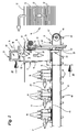
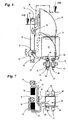
- FIGS. 1 to 7 show parts of a device for cartoning products 10.
- the products 10 are packed in so-called trays 11. At the location of the tray 11 shown but also any other (pack) packs can be used, such as boxes, cartons or the like.
- the trays 11 are made from substantially flat blanks 12 of paper, (corrugated) paperboard, plastic or the like.
- the blanks 12 are removed from a blank stack 13.
- the individual blanks 12 lie flat in the blank stack 13, preferably with a substantially horizontal extent.
- the blank stack 13 may also be in be arranged a blank magazine from which the individual blanks 12 are conveyed out or removed.
- the blanks 12 are fed to a Aufrichtstation 14.
- the substantially flat blanks 12 are prepared by erecting parts of the blank 12, for example by folding up longitudinal walls or transverse walls for receiving the products 10.
- a part of the upright side walls 15 of the tray 11 is formed in the erecting station 14.
- further side walls, in particular all side walls can be erected in the erection station 14.
- the blanks 12 are conveyed individually in front of an opening 16 of a forming shaft 17 of the erecting station 14.
- the opening 16 is delimited by at least two walls of the mold shaft 17, which are arranged opposite one another and are arranged substantially vertically in a lower region and preferably run flat.
- the side walls 19 are widened in a funnel shape, preferably with a circular radius in the region of the widening. Subsequently, the side walls extend approximately horizontally as a bearing surface for the blanks 12.
- Two other side walls of the rectangular shape in the planer shaft 17 are open, so as not to interfere with the path of movement of the forming punch 20.
- the size of the opening 16 is dimensioned such that the blank 12 rests on the funnel-shaped side walls 19 in the region of two opposite edges. Transverse thereto, the blank 12 has a dimension, for example, a width which is less than the inside width of the forming shaft 17th
- the blanks 12 are each individually pressed by a forming die 20 into the forming chute 17, under erection of parts of the blank 12 by abutment in the region of the funnel-shaped narrowing in the conveying direction side walls 19 of the forming chute 17.
- the die 20 is aligned approximately horizontally.
- the partially folded or erected blanks 12 are conveyed downwards by the forming punch 20 in the forming chute 17 in an approximately vertical direction and are transferred directly to a conveying means 21 extending underneath the forming chute 17 which removes the partially folded blanks 12 from the area of the forming chute 17.
- a first peculiarity of Aufrichtstation 14 is the return of the forming die 20 in front of the opening 16 of the mold shaft 17 after pressing a blank 12 in the mold shaft 17.
- the shaping punches 20, 22 are successively moved through the forming shaft 17, each forming punch 20, 22 each pressing a single blank 12 into the forming shaft 17.
- the shaping punches 20, 22 are arranged such that they are moved with (temporal and spatial) distance from one another through the forming shaft 17.
- the other forming die 20 is pivoted about the opening 16 at about this time for impressing the subsequent blank 12th In this way, a doubling of the clock rate is achieved in the case shown.
- the distance of the successive forming dies 20, 22 is dimensioned such that a sufficient space for moving out of the lower punch 20, 22 is available.
- more than two forming dies 20, 22 may be provided.
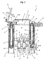
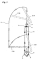
- the forming dies 20, 22 are moved out of the forming shaft 17 (FIG. 3).
- the forming dies 20, 22 are first pivoted about a pivot point 23 in an approximately vertical orientation and thereby moved out of the mold shaft 17.
- the pivoting of the dies 20, 22 takes place counter to the Eindschreibraum the blanks 12.
- the forming dies 20, 22 are moved upward, wherein the vertical alignment of the forming dies 20, 22 is maintained. In an upper end position, the forming punches 20, 22 are pivoted back into an approximately horizontal position in front of the opening 16 of the forming shaft 17.
- Fig. 3 shows this sequence of movements schematically for the forming die 22 shown in FIG.
- the forming punch 20 is moved in an analogous manner.
- the movement sequence of the forming punch 20 can be seen in mirror image to the movement sequence of the forming punch 22 shown in FIG. 3, since the two forming punches 20, 22 are arranged opposite one another on the forming chute 17. Furthermore, it is possible to superimpose the movement of the forming dies 20, 22 in the vertical direction with the pivoting or rotating movement.
- the two forming dies 20, 22 are each driven by an endless conveyor.
- a drive motor 24 drives via a drive shaft 25, two toothed belts 26 as endless conveyors, which are arranged in a vertical direction on both sides of the forming shaft 17 and each of which a forming die 20, 22 is assigned.
- the drive shaft 25 is coupled in each case with an upper gear 27, which drives the toothed belt 26.
- the direction of movement of the toothed belt 26 is opposite, as indicated by arrows in Fig. 2.
- lower gears 28 are provided, over which the toothed belts 26 are guided.
- each shaping die 20, 22 is assigned its own toothed belt 26.
- the forming dies 20, 22 lying on the same side of the forming chute 17 can preferably be driven by a common toothed belt 26.
- the toothed belts 26 are each coupled to a driver 29.
- the drivers 29 are coupled in the region of a lateral free end 30 with the toothed belt 26.
- the adjacent free lateral end 30 of the driver 29 is also movably mounted in an oval curve trace 31, namely via an annular bearing bush 32.
- the curve trace 31 is formed as a recess in a bearing block 33, which is otherwise substantially rectangular in plan. This bearing block 33 extends at least over the entire height of the toothed belt 26.
- Another opposite lateral end 34 of the driver 29 extends through a bore 35 in the dies 20, 22.
- the forming dies 20, 22 in Area of a lateral free end of the carriers 29 stored.
- the advantageous movement path 37 of the forming dies 20, 22 as shown schematically in Fig. 3.
- the shaping punches 22 are approximately L-shaped in cross-section with a first longer leg 38 and a second shorter leg 39.
- the shorter leg 39 is also angled or cranked.
- the longer legs 38 of the forming punches 20, 22 in the plan are partially rectangular or square.
- these have a central recess 40.
- the attachment of the forming dies 20, 22 to the drivers 29 is, as already described, arranged in the region of a lateral end of the forming dies 20, 22, namely in the vicinity of the bent portion.
- the second pivot point 23 is also formed.
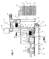
- the forming dies 20, 22 are rotatably mounted on an axle 41, which in turn cantilevered on a movable up and down slide 42 is mounted.
- the carriage 42 is movably mounted on two guide rails 43 in an exclusively vertical direction.
- the guide rails 43 are associated with the bearing blocks 33 and extend on both sides of the toothed belt 26.
- the guide rails 43, the path of movement of the axis 41 and the pivot point 23 is predetermined. This is therefore only movable in the vertical direction, namely up or down.
- the conveying path of the blanks in the forming shaft 17 is followed by a laterally directed transport of the partially folded blanks 12.
- the conveyor 21 is provided.
- the conveying means 21 are preferably one or more parallel (endless) conveyor belts 45, which are driven by deflection rollers 46.
- the conveyor belt (s) 45 may be disposed below the mold cavity 17 or may extend partially therethrough.
- two parallel conveyor belts 45 are provided as an endless conveyor, the deflection rollers 46 are arranged on a common axis 47.
- the partially folded blanks 12 are deposited on the conveyor belts 45 by the shaping punches 20, 22, namely exactly between drivers 48, which are arranged on the outside of the conveyor belts 45.
- the drivers 48 are each arranged in pairs, wherein the mutually facing upright side surfaces of the paired drivers 48 are provided with a chamfer. The space between the pairs of drivers 48 is thereby extended upward.
- the minimum distance of the paired driver 48 corresponds approximately to the corresponding cross-sectional dimension of the trays 11.
- the partially folded blanks 12 are conveyed out of the Aufrichtstation 14 side.
- further side walls are erected or folded upwards and connected to the already erected side walls 15, for example by applying glue.
- the erection of the remaining side walls and bonding with the folded in the Aufrichtstation 14 side walls 15 is preferably carried out after the products 11 were deposited from above on or in the partially folded blank 12.
- the erection or folding up of the remaining side walls can be done with the help of special Folding organs or folding rails done.
- the glue is preferably applied in the region of folding tabs 49.
- the described device or the method for erecting the blanks 12 is preferably carried out completely continuously. This also applies to the feeding of the blanks 12 from the blank stack 13 and the lateral removal of the partially folded blanks 12 on the conveyor 21st
- FIGS. 5 to 7 show a second, preferred exemplary embodiment. If the following described organs of this device functionally correspond to the organs described in the first exemplary embodiment, matching designations or reference symbols are used.
- the device shown in the second embodiment differs from the embodiment of FIGS. 1 to 4 only in terms of the structural design of the erection station 14, namely with respect to the means provided for carrying out the movement of the forming dies 20, 22 means.
- the pushing-in movement of the forming punches 20, 22 and the removal of the same from the forming shaft 17 is essentially identical to the first embodiment.
- the blanks 12 are removed individually from a blank stack 13 and moved in front of the opening 16 of a mold shaft 17. There, the individual blanks 12 are detected by a forming die 20, 22 on the upper side and pressed into the mold shaft 17, wherein the blank 12 is at least partially erected.
- an endless conveyor of two parallel conveyor belts 45 is arranged below the mold shaft 17 as in the first embodiment. Individual blanks 12 are deposited by the forming dies 20, 22 between drivers 48 at the top of the conveyor belts 45.
- the conveyor 21 formed by the conveyor belts 45 is designed as a preferably continuously operated endless conveyor and serves for The folding out or erecting of the blanks 12 is completed as in the first exemplary embodiment during further lateral or horizontal transport on the conveyor 21.
- two forming dies 20, 22 are provided.
- the shaping punches 20, 22 are arranged here in plan view on the same side of the molding shaft 17.
- the forming punches 20, 22 are each pivotally mounted on a carriage 50 which is movable along a linear axis 51.
- the linear axes 51 are arranged substantially vertically aligned in the illustrated embodiment, so that the forming dies 20, 22 along the linear axes 51 in the vertical direction can be moved up or down.
- the carriage 50 is in each case associated with a servomotor 52, which allows a pivoting of the mounted on the carriage 50 forming dies 20, 22 about a pivot point 23.
- the forming dies 20, 22 are successively pivoted one after the other on the upper side for abutment against a blank 12 lying flat on the side walls 19 of the forming shaft 17.
- the carriages 50 By moving the carriages 50 downwards in a substantially vertical direction, the blanks 12 are individually pressed into the forming shaft 17 with at least partial erection of the blanks 12.
- the forming punches 20, 22 are aligned approximately horizontally. In a lower end position of the carriages 50, the blanks 12 are transferred to the conveying means 21 by the shaping punches 20, 22.
- the forming dies 20, 22 are pivoted out of the forming shaft 17 counter to the indentation direction about the pivot point 23 into an upright, substantially vertical position. Thereafter, the carriages 50 are moved upward to an upper end position, wherein the substantially vertical alignment of the forming dies 20, 22 is maintained. Finally, the dies 20, 22 are pivoted in the direction of depression in the approximately horizontal position in which the dies 20, 22 at the level of the opening 16 of the mold shaft 17 on the upper side abut the blanks 12.
- the shaping punches 20, 22 are moved through the forming shaft 17 in a temporally and spatially displaced manner, so that, after pivoting back a lower forming punch 22, the upper forming punch 20 can be moved into the forming shaft 17 with a blank 12.
- the returning of the forming dies 20, 22 into an upper starting position can thus take place while the respective other forming punch 20, 22 is already moved through the forming chute 17.
- a doubling of the clock rate is achieved as in the first embodiment.
- the pivoting back of the forming dies 20, 22 takes place as in the first embodiment against the Eindrückraum the blanks.
- the moving back of the forming dies 20, 22 in front of the opening 16 as in the first embodiment substantially outside of the mold shaft 17.
- the pivoting movement can be superimposed with the up and / or downward movement.
- the linear axes 51 each include endless conveyors, for example continuously driven, circulating toothed belts, straps or the like, each of which is guided over a lower deflection roller 53 and an upper, common transmission shaft 54.
- the two circulating conveyor belts in the linear axes 51 are driven by a common servo motor 55, which is coupled to the transmission shaft 54.
- the opposite movement of the two forming dies 20, 22 results from the respective arrangement of the carriages 50 on opposite conveying paths of the respective endless conveyors of the linear axes 51.
- the carriage 50 associated with the forming die 20 is attached to a the forming shaft 17 facing conveying strand arranged, whereas the forming die 22 associated carriage 50 is disposed on a side facing away from the forming shaft 17 conveying strand of the linear axis 51 (Fig. 7).
- the two linear axes are arranged in plan on the same side of the conveyor belts 45 of the conveyor 21.
- a linear axis 51 is arranged approximately at the level of the forming shaft 17, wherein the second linear axis 51, which moves the forming punch 20 in the embodiment shown, is arranged laterally offset from the forming shaft 17.
- arms 56, 57 which connect the forming dies 20, 22 in each case to the corresponding slide 50 are angled or cranked.
- the arms 56, 57 each formed in plan and in the side view double angled, for bridging the distance between the linear axes 51 and the mold shaft 17th
Abstract
Description
Die Erfindung betrifft ein Verfahren zum Aufrichten von (flachen) Zuschnitten für Kartons, Faltschachteln, Trays oder dergleichen, wobei die Zuschnitte vor eine Öffnung eines Formschachts bewegt und mit einem, insbesondere auf- und abbewegbaren, Formstempel in den Formschacht eingedrückt werden, unter Aufrichtung von Teilen des Zuschnitts, insbesondere im Bereich von Längswänden und/oder Querwänden des Kartons oder dergleichen. Weiterhin betrifft die Erfindung eine entsprechende Vorrichtung.The invention relates to a method for erecting (flat) blanks for cartons, cartons, trays or the like, wherein the blanks moved in front of an opening of a mold shaft and pressed with a, in particular movable up and down, forming die in the mold shaft, under erection of Parts of the blank, in particular in the region of longitudinal walls and / or transverse walls of the carton or the like. Furthermore, the invention relates to a corresponding device.
Bei bekannten Vorrichtungen der eingangs genannten Art wird zunächst ein Zuschnitt vor die Öffnung eines Formschachts bewegt und durch den Formstempel in den Formschacht eingedrückt, wobei Teile des Zuschnitts aufgerichtet bzw. gefaltet werden. Nachfolgend wird der Formstempel aus dem Formschacht herausgezogen und der nächste Zuschnitt vor die Öffnung des Formschachts bewegt, worauf sich der gesamte Vorgang wiederholt.
Siehe z.B. GB 1.103.189.In known devices of the type mentioned initially a blank is moved in front of the opening of a mold shaft and pressed by the forming die into the mold shaft, wherein parts of the blank are erected or folded. Subsequently, the forming die is pulled out of the mold shaft and moves the next blank in front of the opening of the mold shaft, whereupon the entire process is repeated.
See eg GB 1.103.189.
Der Erfindung liegt die Aufgabe zugrunde ein Verfahren und eine Vorrichtung der eingangs genannten Art weiterzuentwickeln, insbesondere Maßnahmen vorzuschlagen, die zu einer Erhöhung der Arbeitsgeschwindigkeit führen.The invention has the object of further developing a method and an apparatus of the type mentioned, in particular to propose measures that lead to an increase in the operating speed.
Zur Lösung dieser Aufgabe ist das erfindungsgemäße Verfahren dadurch gekennzeichnet, dass der Formstempel nach dem Eindrücken eines Zuschnitts in den Formschacht mindestens teilweise außerhalb des Formschachts zurückbewegt wird in eine Position vor die Öffnung des Formschachts. Die Formstempel werden dabei entgegen der Eindrückrichtung der Zuschnitte aus dem Formschacht herausbewegt, insbesondere herausgeschwenkt. Vorzugsweise wird der Formstempel also nicht durch die Öffnung zurückbewegt, sondern zumindest in einem (Teil-) Bereich außerhalb der Formschachts geführt. Auf diese Weise kann der nächste aufzurichtende Zuschnitt schon vor die Öffnung des Formschachts bewegt, insbesondere gefördert werden, bevor der Formstempel seine Ausgangsposition vor der Öffnung des Formschachts erreicht hat.To solve this problem, the method according to the invention is characterized in that the molding die is moved back after pressing a blank in the mold shaft at least partially outside of the mold shaft in a position in front of the opening of the mold shaft. The forming dies are thereby moved out of the mold shaft contrary to the indentation direction of the blanks, in particular swung out. Preferably, the forming punch is thus not moved back through the opening, but at least in a (part) area out of the mold shaft. In this way, the next blank to be erected even before the opening of the Shaping shaft moves, in particular promoted before the forming die has reached its starting position in front of the opening of the forming shaft.
Gemäß einer vorteilhaften Weiterbildung der Erfindung ist vorgesehen, dass dem Formschacht mindestens zwei Formstempel zugeordnet sind, die nacheinander zum Eindrücken jeweils eines (einzelnen) Zuschnitts in den Formschacht bewegt werden. Auf diese Weise kann die Arbeitsgeschwindigkeit der Vorrichtung verdoppelt werden, bei gleich bleibender Geschwindigkeit der Formstempel. In einer bevorzugten Ausführungsform der Erfindung sind zwei Formstempel vorgesehen, die derart zeitlich versetzt zueinander betrieben werden, dass ein zweiter Formstempel einen Zuschnitt durch die Öffnung des Formschachts drückt, wenn ein erster Formstempel die Aufrichtung eines anderen Zuschnitts im Wesentlichen fertig gestellt hat, insbesondere diesen Zuschnitt einem Fördermittel zum. Abtransport der mindestens teilweise aufgerichteten Zuschnitte übergibt.According to an advantageous embodiment of the invention it is provided that the forming shaft are associated with at least two forming dies, which are successively moved to impress each one (single) blank in the forming shaft. In this way, the operating speed of the device can be doubled, while maintaining the speed of the forming die. In a preferred embodiment of the invention, two forming dies are provided, which are operated offset in time from one another such that a second forming punch presses a blank through the opening of the forming chute when a first forming punch has substantially completed the erection of another blank, in particular this blank a subsidy to. Removal of at least partially erected blanks transfers.
Vorzugsweise werden die Zuschnitte kontinuierlich zugeführt und auch die Formstempel kontinuierlich angetrieben, so dass Belastungen der Vorrichtung durch einen taktweisen Betrieb vermieden werden können.Preferably, the blanks are fed continuously and the forming dies are driven continuously, so that loads on the device can be avoided by a cyclic operation.
Eine Vorrichtung zur Lösung der eingangs genannten Aufgabe weist die Merkmale des Anspruchs 10 auf. Vorzugsweise sind ebenfalls mindestens zwei Formstempel vorgesehen, die nacheinander durch den Formschacht bewegbar sind. Die Formstempel können drehbar, insbesondere schwenkbar an jeweils einem außerhalb des Formschachts auf- und abbewegbaren Laufwagen oder Schlitten gelagert sein und werden vorzugsweise durch jeweils einen kontinuierlich angetriebenen Gurt bewegt.An apparatus for solving the above-mentioned problem has the features of
Bevorzugte Weiterbildungen des erfindungsgemäßen Verfahrens und der Vorrichtung ergeben sich aus den Unteransprüchen und der Beschreibung im Übrigen. Ein Ausführungsbeispiel der Erfindung wird nachfolgend anhand der Zeichnung dargestellt. Es zeigt:
- Fig. 1
- eine Vorrichtung zum Aufrichten von Zuschnitten in einer schematischen Seitenansicht,
- Fig. 2
- die Vorrichtung gemäß Fig. 1 in einem Vertikalschnitt,
- Fig. 3
- eine schematische Darstellung des Bewegungsablaufs eines Formstempels der Vorrichtung,
- Fig. 4
- ein Querschnitt durch einen Teil der Vorrichtung in vergrößertem Maßstab,
- Fig. 5
- eine alternative Ausführungsform der Vorrichtung gemäß Fig. 1 in einer schematischen Seitenansicht,
- Fig. 6
- die Vorrichtung gemäß Fig.5 in einem Vertikalschnitt entlang Schnittline Vl-Vl, und
- Fig. 7
- ein horizontaler Schnitt durch die Vorrichtung entlang Schnittlinie VII-VII in Fig. 6.
- Fig. 1
- a device for erecting blanks in a schematic side view,
- Fig. 2
- the apparatus of FIG. 1 in a vertical section,
- Fig. 3
- a schematic representation of the sequence of movement of a forming die of the device,
- Fig. 4
- a cross-section through a part of the device in an enlarged scale,
- Fig. 5
- an alternative embodiment of the device according to FIG. 1 in a schematic side view,
- Fig. 6
- the device according to Figure 5 in a vertical section along section line Vl-Vl, and
- Fig. 7
- a horizontal section through the device along section line VII-VII in Fig. 6.
Die Figuren 1 bis 7 zeigen Teile einer Vorrichtung zum Kartonieren von Produkten 10. Die Produkte 10 werden dabei in sogenannte Trays 11 verpackt. An der Stelle der gezeigten Trays 11 können aber auch beliebige andere (Gebinde-)Packungen zum Einsatz kommen, beispielsweise Kartons, Faltschachteln oder dergleichen.FIGS. 1 to 7 show parts of a device for
Die Trays 11 werden aus im Wesentlichen flachen Zuschnitten 12 aus Papier, (Well-) Pappe, Kunststoff oder dergleichen hergestellt. Hierzu werden die Zuschnitte 12 einem Zuschnitt-Stapel 13 entnommen. Die einzelnen Zuschnitte 12 liegen im Zuschnitt-Stapel 13 flach übereinander, vorzugsweise mit im Wesentlichen horizontaler Erstreckung. Der Zuschnitt-Stapel 13 kann auch in einem Zuschnitt-Magazin angeordnet sein, aus dem die einzelnen Zuschnitte 12 herausgefördert bzw. entnommen werden.The
Zur Bildung der Trays 11 bzw. von Kartons, Faltschachteln oder dergleichen werden die Zuschnitte 12 einer Aufrichtstation 14 zugeführt. ln dieser Station werden die im Wesentlichen flachen Zuschnitte 12 durch Aufrichten von Teilen des Zuschnitts 12, beispielsweise durch Hochfalten von Längswänden bzw. Querwänden für die Aufnahme der Produkte 10 vorbereitet. Im gezeigten Ausführungsbeispiel wird ein Teil der aufrechten Seitenwände 15 des Trays 11 in der Aufrichtstation 14 gebildet. Je nach Art der herzustellenden Verpackung können aber auch weitere Seitenwände, insbesondere sämtliche Seitenwände in der Aufrichtstation 14 aufgerichtet werden.To form the
Die Besonderheiten der Aufrichtstation 14 werden nachfolgend in Verbindung mit den Figuren 1 bis 4 für ein erstes Ausführungsbeispiel erläutert:The special features of the
Die Zuschnitte 12 werden einzeln vor eine Öffnung 16 eines Formschachts 17 der Aufrichtstation 14 gefördert. Die Öffnung 16 wird durch wenigstens zwei Wände des Formschachts 17 begrenzt, die gegenüberliegend angeordnet sind und in einem unteren Bereich im Wesentlichen senkrecht angeordnet sind und vorzugsweise eben verlaufen. lm Bereich der Öffnung 16 sind die Seitenwände 19 trichterförmig aufgeweitet, vorzugsweise mit einem kreisförmigen Radius im Bereich der Aufweitung. Daran anschließend verlaufen die Seitenwände etwa horizontal als Auflagefläche für die Zuschnitte 12. Zwei andere Seitenwände des im Grundriss rechteckigen Formschachts 17 sind offen ausgebildet, um die Bewegungsbahn des Formstempels 20 nicht zu beeinträchtigen. Die Größe der Öffnung 16 ist derart bemessen, dass der Zuschnitt 12 im Bereich von zwei gegenüberliegenden Rändern auf den trichterförmigen Seitenwänden 19 aufliegt. Quer hierzu weist der Zuschnitt 12 eine Abmessung, beispielsweise eine Breite auf, die geringer ist als die lichte Weite des Formschachts 17.The
Die Zuschnitte 12 werden jeweils einzeln durch einen Formstempel 20 in den Formschacht 17 eingedrückt, unter Aufrichtung von Teilen des Zuschnitts 12 durch Anlage im Bereich der trichterförmig sich in Förderrichtung verengenden Seitenwände 19 des Formschachts 17. Vorzugsweise während des kompletten Eindrückens der Zuschnitte in den Formschacht 17 ist der Formstempel 20 etwa horizontal ausgerichtet. Die teilweise gefalteten bzw. aufgerichteten Zuschnitte 12 werden durch den Formstempel 20 im Formschacht 17 in etwa vertikaler Richtung abwärts befördert und unmittelbar an ein unterhalb des Formschachts 17 verlaufendes Fördermittel 21 übergeben, das die teilweise gefalteten Zuschnitte 12 aus dem Bereich des Formschachts 17 abtransportiert.The
Eine erste Besonderheit der Aufrichtstation 14 besteht in der Zurückführung des Formstempels 20 vor die Öffnung 16 des Formschachts 17 nach dem Eindrücken eines Zuschnitts 12 in den Formschacht 17. Nach der Übergabe der Zuschnitte 12 an das Fördermittel 21 wird der Formstempel 20 aus dem Formschacht 17 herausbewegt und nach oben geführt, so dass der Formstempel 20 zumindest teilweise außerhalb des Formschachts 17 zurück vor die Öffnung 16 bewegt wird. Auf diese Weise kann während der Zurückbewegung des Formstempels 20 der nächste Zuschnitt 12 in den Bereich der Öffnung 16 gefördert werden. Dadurch können die Zuschnitte 12 kontinuierlich vor die Öffnung 16 bewegt bzw. gefördert werden.A first peculiarity of
Eine weitere Besonderheit besteht darin, dass dem (einzelnen) Formschacht 17 mehrere Formstempel 20, 22 zugeordnet sind. Die Formstempel 20, 22 werden nacheinander durch den Formschacht 17 hindurchbewegt, wobei jeder Formstempel 20, 22 jeweils einen einzelnen Zuschnitt 12 in den Formschacht 17 eindrückt. Die Formstempel 20, 22 sind derart angeordnet, dass sie mit (zeitlichem und räumlichen) Abstand zueinander durch den Formschacht 17 bewegt werden. Im gezeigten Ausführungsbeispiel ist vorgesehen, dass bei Übergabe eines Zuschnitts 12 durch den Formstempel 22 an das Fördermittel 21 der andere Formstempel 20 etwa zu diesem Zeitpunkt vor die Öffnung 16 geschwenkt wird zum Eindrücken des darauf folgenden Zuschnitts 12. Auf diese Weise wird im gezeigten Fall eine Verdopplung der Taktrate erzielt. Der Abstand der aufeinander folgenden Formstempel 20, 22 ist derart bemessen, dass ein ausreichender Platz zum Herausbewegen des unteren Formstempels 20, 22 zur Verfügung steht. Alternativ können auch mehr als zwei Formstempel 20, 22 vorgesehen sein.Another special feature is that the (single)
Ebenfalls von Bedeutung ist die Weise in der die Formstempel 20, 22 aus dem Formschacht 17 herausbewegt werden (Fig. 3). Nach der Übergabe eines Zuschnitts 12 an das Fördermittel 21 werden die Formstempel 20, 22 zunächst um einen Drehpunkt 23 in eine etwa vertikale Ausrichtung geschwenkt und dabei aus dem Formschacht 17 herausbewegt. Das Verschwenken der Formstempel 20, 22 erfolgt dabei entgegen der Eindrückrichtung der Zuschnitte 12. Vorzugsweise nach abgeschlossener Schwenkbewegung werden die Formstempel 20, 22 aufwärts bewegt, wobei die vertikale Ausrichtung der Formstempel 20, 22 beibehalten wird. In einer oberen Endstellung werden die Formstempel 20, 22 zurück in eine etwa waagerechte Position geschwenkt vor die Öffnung 16 des Formschachts 17. Daran schließt sich die vertikale Abwärtsbewegung der Formstempel 20, 22 an, wobei diese etwa horizontal ausgerichtet sind und vorzugsweise vollflächig auf einem Zuschnitt 12 aufliegen. Der Bewegungszyklus endet mit der Übergabe der Zuschnitte 12 in das Fördermittel 21. Fig. 3 zeigt diesen Bewegungsablauf schematisch für den in Fig. 2 gezeigten Formstempel 22.Also of importance is the manner in which the forming dies 20, 22 are moved out of the forming shaft 17 (FIG. 3). After the transfer of a blank 12 to the
Es versteht sich, dass der Formstempel 20 in analoger Weise bewegt wird. Der Bewegungsablauf des Formstempels 20 ist spiegelbildlich zu dem in Fig. 3 dargestellten Bewegungsablauf des Formstempels 22 zu sehen, da die beiden Formstempel 20, 22 gegenüberliegend am Formschacht 17 angeordnet sind. Weiterhin ist es möglich die Bewegung der Formstempel 20, 22 in vertikaler Richtung mit der Schwenk- bzw. Drehbewegung zu überlagern.It is understood that the forming
Die beiden Formstempel 20, 22 werden jeweils durch einen Endlosförderer angetrieben. Ein Antriebsmotor 24 treibt über eine Antriebswelle 25 zwei Zahnriemen 26 als Endlosförderer an, die in vertikaler Richtung umlaufend beiderseits des Formschachts 17 angeordnet sind und denen jeweils ein Formstempel 20, 22 zugeordnet ist. Hierzu ist die Antriebswelle 25 jeweils mit einem oberen Zahnrad 27 gekoppelt, das den Zahnriemen 26 antreibt. Die Bewegungsrichtung der Zahnriemen 26 ist gegenläufig, wie durch Pfeile in Fig. 2 angedeutet. Weiterhin sind jeweils untere Zahnräder 28 vorgesehen, über die die Zahnriemen 26 geführt werden. Im gezeigten Ausführungsbeispiel ist jedem Formstempel 20, 22 ein eigener Zahnriemen 26 zugeordnet. Bei mehr als zwei Formstempeln 20, 22 können die jeweils auf der gleichen Seite des Formschachts 17 liegenden Formstempel 20, 22 vorzugsweise durch einen gemeinsamen Zahnriemen 26 angetrieben werden.The two forming dies 20, 22 are each driven by an endless conveyor. A
Zur Bewegung der Formstempel 20, 22 sind die Zahnriemen 26 jeweils mit einem Mitnehmer 29 gekoppelt. Die Mitnehmer 29 sind dabei im Bereich eines seitlichen freien Endes 30 mit den Zahnriemen 26 gekoppelt. Das benachbarte freie seitliche Ende 30 der Mitnehmer 29 ist zudem in einer ovalen Kurvenspur 31 verfahrbar gelagert, nämlich über eine ringförmige Lagerbuchse 32. Die Kurvenspur 31 ist als Ausnehmung in einem ansonsten im Grundriss im Wesentlichen rechteckigen Lagerblock 33 gebildet. Dieser Lagerblock 33 erstreckt sich mindestens über die gesamte Höhe des Zahnriemens 26. Ein anderes gegenüberliegendes seitliches Ende 34 der Mitnehmer 29 erstreckt sich durch eine Bohrung 35 in den Formstempeln 20, 22. Wie aus Fig. 2 ersichtlich, sind die Formstempel 20, 22 im Bereich eines seitlichen freien Endes an den Mitnehmern 29 gelagert. Durch den Antrieb des Zahnriemens 26 um die Zahnräder 27, 28 wird der Mitnehmer 29 in der Kurvenspur 31 entlang der in Fig. 3 gezeigten ovalen Bewegungsbahn 36 geführt.To move the forming dies 20, 22, the
In Verbindung mit der Gestalt der Formstempel 20, 22 und der Anordnung des Drehpunkts 23 ergibt sich die vorteilhafte Bewegungsbahn 37 der Formstempel 20, 22 wie schematisch in Fig. 3 dargestellt ist. Wie aus Fig. 2 ersichtlich sind die Formstempel 22 im Querschnitt etwa L-förmig ausgebildet mit einem ersten längeren Schenkel 38 und einem zweiten kürzeren Schenkel 39. Der kürzere Schenkel 39 ist zudem abgewinkelt bzw. gekröpft ausgebildet. Zur Anlage am Zuschnitt 12 sind die längeren Schenkel 38 der Formstempel 20, 22 im Grundriss teilweise rechteckig bzw. quadratisch ausgebildet. Zur Reduzierung des Gewichts der Formstempel 20, 22 weisen diese eine zentrale Ausnehmung 40 auf. Die Befestigung der Formstempel 20, 22 an den Mitnehmern 29 ist, wie bereits beschrieben, im Bereich eines seitlichen Endes der Formstempel 20, 22 angeordnet, nämlich in der Nähe des abgekröpften Bereichs. Zentral im abgewinkelten bzw. abgekröpften Bereich ist zudem der zweite Drehpunkt 23 ausgebildet. Hierzu sind die Formstempel 20, 22 drehbar an einer Achse 41 gelagert, die ihrerseits auskragend an einem auf- und abbewegbaren Schlitten 42 gelagert ist. Der Schlitten 42 ist an zwei Führungsschienen 43 in ausschließlich vertikaler Richtung verfahrbar gelagert. Die Führungsschienen 43 sind den Lagerblöcken 33 zugeordnet und verlaufen beiderseits der Zahnriemen 26. Durch die Führungsschienen 43 wird die Bewegungsbahn der Achse 41 bzw. des Drehpunkts 23 vorgegeben. Dieser ist demnach lediglich in vertikaler Richtung bewegbar, nämlich auf- bzw. abwärts.In conjunction with the shape of the forming dies 20, 22 and the arrangement of the
Durch die Lagerung der Formstempel 20, 22 am vertikal auf- und abbewegbaren Drehpunkt 23 bzw. der Achse 41 und der weiteren Lagerung am angetriebenen und entlang der Kurvenspur 31 bewegbaren Kombinationen aus Zahnriemen 26 und Mitnehmern 29 stellt sich die in Fig. 3 schematisch gezeigte Bewegung der Formstempel 20, 22 ein. Die Schenkel 38 zur Auflage an den Zuschnitten 12 werden oberhalb der Öffnung 16 vor diese geschwenkt und in den Formschacht hereinbewegt unter Mitnahme und Aufrichtung eines einzelnen Zuschnitts 12. Die Formstempel 20, 22 werden zusammen mit dem Zuschnitt 12 soweit abwärts im Formschacht 17 bewegt, bis die Zuschnitte 12 zur Anlage am Fördermittel 21 gelangen. Danach werden die Formstempel 20, 22 entgegen der vertikalen Förderrichtung der Zuschnitte 12 seitlich aus dem Formschacht 17 herausgeschwenkt und außerhalb desselben zurück in eine Position vor die Öffnung 16 des Formschachts zurückbewegt. Der Antrieb der Zahnriemen 26 erfolgt dabei kontinuierlich.By the storage of the forming dies 20, 22 on the vertically upwardly and downwardly
An den Förderweg der Zuschnitte im Formschacht 17 schließt sich ein seitwärts gerichteter Transport der teilweise gefalteten Zuschnitte 12 an. Hierzu ist das Fördermittel 21 vorgesehen. Bei dem Fördermittel 21 handelt es sich vorzugsweise um einen oder mehrere parallel angeordnete (endlose) Fördergurte 45, die durch Umlenkrollen 46 angetrieben werden. Der oder die Fördergurte 45 können unterhalb des Formschachtes 17 angeordnet sein, oder teilweise durch diesen hindurch verlaufen.The conveying path of the blanks in the forming
Im gezeigten Ausführungsbeispiel sind zwei parallele Fördergurte 45 als Endlosförderer vorgesehen, deren Umlenkrollen 46 auf einer gemeinsamen Achse 47 angeordnet sind. Die teilweise gefalteten Zuschnitte 12 werden wie bereits beschrieben durch die Formstempel 20, 22 auf den Fördergurten 45 abgelegt, nämlich exakt zwischen Mitnehmer 48, die an der Außenseite der Fördergurte 45 angeordnet sind. Die Mitnehmer 48 sind jeweils paarweise angeordnet, wobei die einander zugewandten aufrechten Seitenflächen der paarweisen Mitnehmer 48 mit einer Abschrägung versehen sind. Der Raum zwischen den paarweisen Mitnehmern 48 ist dadurch nach oben hin erweitert. Der minimale Abstand der paarweisen Mitnehmer 48 entspricht dabei etwa der entsprechenden Querschnittsabmessung der Trays 11. Über das Fördermittel 21 werden die teilweise gefalteten Zuschnitte 12 aus der Aufrichtstation 14 seitlich herausgefördert. Nachfolgend werden weitere Seitenwände aufgerichtet bzw. aufwärts gefaltet und mit den bereits aufgerichteten Seitenwänden 15 verbunden, beispielsweise durch Auftragen von Leim. Das Aufrichten der übrigen Seitenwände und das Verkleben mit den in der Aufrichtstation 14 gefalteten Seitenwänden 15 erfolgt vorzugsweise nachdem die Produkte 11 von oben auf bzw. in den teilweise gefalteten Zuschnitt 12 abgesetzt wurden. Das Aufrichten bzw. Hochfalten der übrigen Seitenwände kann mit Hilfe von speziellen Faltorganen oder Faltschienen erfolgen. Der Leim wird vorzugsweise im Bereich von Faltlappen 49 aufgetragen.In the embodiment shown, two
Die beschriebene Vorrichtung bzw. das Verfahren zum Aufrichten der Zuschnitte 12 erfolgt vorzugsweise vollständig kontinuierlich. Dies gilt auch für das Zuführen der Zuschnitte 12 vom Zuschnitt-Stapel 13 und den seitlichen Abtransport der teilweise gefalteten Zuschnitte 12 auf dem Fördermittel 21.The described device or the method for erecting the
In den Fig. 5 bis 7 ist ein zweites, bevorzugtes Ausführungsbeispiel gezeigt. Sofern die nachfolgend beschriebenen Organe dieser Vorrichtung funktional mit den im ersten Ausführungsbeispiel beschriebenen Organen übereinstimmen, werden übereinstimmende Bezeichnungen bzw. Bezugszeichen verwendet.FIGS. 5 to 7 show a second, preferred exemplary embodiment. If the following described organs of this device functionally correspond to the organs described in the first exemplary embodiment, matching designations or reference symbols are used.
Die im zweiten Ausführungsbeispiel gezeigte Vorrichtung unterscheidet sich von dem Ausführungsbeispiel gemäß Fig. 1 bis 4 lediglich hinsichtlich der konstruktiven Ausgestaltung der Aufrichtstation 14, nämlich hinsichtlich der zur Durchführung der Bewegung der Formstempel 20, 22 vorgesehenen Mittel. Die Eindrückbewegung der Formstempel 20, 22 und das Herausführen derselben aus dem Formschacht 17 ist im Wesentlichen identisch mit dem ersten Ausführungsbeispiel.The device shown in the second embodiment differs from the embodiment of FIGS. 1 to 4 only in terms of the structural design of the
Wie im ersten Ausführungsbeispiel werden die Zuschnitte 12 einzeln von einem Zuschnitt-Stapel 13 entnommen und vor die Öffnung 16 eines Formschachts 17 bewegt. Dort werden die vereinzelten Zuschnitte 12 von einem Formstempel 20, 22 oberseitig erfasst und in den Formschacht 17 hineingedrückt, wobei der Zuschnitt 12 wenigstens teilweise aufgerichtet wird. Unterhalb des Formschachts 17 ist wie im ersten Ausführungsbeispiel ein Endlosförderer aus zwei parallelen Fördergurten 45 angeordnet. Einzelne Zuschnitte 12 werden durch die Formstempel 20, 22 zwischen Mitnehmer 48 an der Oberseite der Fördergurte 45 abgelegt. Das durch die Fördergurte 45 gebildete Fördermittel 21 ist als vorzugsweise kontinuierlich betriebener Endlosförderer ausgebildet und dient zum seitlichen Herausfördern der wenigstens teilweise gefalteten bzw. aufgerichteten Zuschnitte 12 aus der Aufrichtstation 14. Die Komplettierung der Faltung bzw. des Aufrichtens der Zuschnitte 12 erfolgt wie im ersten Ausführungsbeispiel während des weiteren seitlich bzw. horizontal gerichteten Transports auf dem Fördermittel 21.As in the first embodiment, the
Wie im ersten Ausführungsbeispiel sind zwei Formstempel 20, 22 vorgesehen. Im Unterschied zum vorhergehenden Ausführungsbeispiel sind die Formstempel 20, 22 hier im Grundriss an der gleichen Seite des Formschachts 17 angeordnet. Die Formstempel 20, 22 sind jeweils schwenkbar an einem Schlitten 50 gelagert, der entlang einer Linearachse 51 bewegbar ist. Die Linearachsen 51 sind im gezeigten Ausführungsbeispiel im Wesentlichen vertikal ausgerichtet angeordnet, so dass die Formstempel 20, 22 entlang der Linearachsen 51 in vertikaler Richtung auf- bzw. abbewegbar sind. Den Schlitten 50 ist jeweils ein Servomotor 52 zugeordnet, der ein Verschwenken der an den Schlitten 50 gelagerten Formstempel 20, 22 um einen Drehpunkt 23 ermöglicht.As in the first embodiment, two forming dies 20, 22 are provided. In contrast to the previous exemplary embodiment, the shaping punches 20, 22 are arranged here in plan view on the same side of the
Mit Hilfe der auf- und abbewegbaren Schlitten 50 und den schwenkbar daran befestigten Formstempeln 20, 22 lässt sich der geschilderte Bewegungsablauf wie im ersten Ausführungsbeispiel umsetzen. Die Formstempel 20, 22 werden nacheinander jeweils oberseitig zur Anlage an einem flach auf den Seitenwänden 19 des Formschachts 17 aufliegenden Zuschnitt 12 geschwenkt. Durch Abwärtsbewegung der Schlitten 50 in im Wesentlichen vertikaler Richtung werden die Zuschnitte 12 einzeln in den Formschacht 17 eingedrückt unter wenigstens teilweiser Aufrichtung der Zuschnitte 12. Während des kompletten Eindrückvorgangs sind die Formstempel 20, 22 dabei etwa horizontal ausgerichtet. ln einer unteren Endstellung der Schlitten 50 werden die Zuschnitte 12 durch die Formstempel 20, 22 an das Fördermittel 21 übergeben. Daraufhin werden die Formstempel 20, 22 entgegen der Eindrückrichtung um den Drehpunkt 23 aus dem Formschacht 17 herausgeschwenkt in eine aufrechte, im Wesentlichen vertikale Stellung. Danach werden die Schlitten 50 aufwärts bewegt bis in eine obere Endstellung, wobei die im wesentlichen vertikale Ausrichtung der Formstempel 20, 22 beibehalten wird. Abschließend werden die Formstempel 20, 22 in Eindrückrichtung in die etwa horizontale Stellung geschwenkt, in der die Formstempel 20, 22 auf Höhe der Öffnung 16 des Formschachts 17 oberseitig an den Zuschnitten 12 anliegen.With the help of the movable up and down
Die Formstempel 20, 22 werden wie im ersten Ausführungsbeispiel zeitlich und räumlich beabstandet bzw. versetzt durch den Formschacht 17 hindurchbewegt, so dass nach dem Zurückschwenken eines unteren Formstempels 22 der obere Formstempel 20 mit einem Zuschnitt 12 in den Formschacht 17 hineinbewegt werden kann. Das Zurückführen der Formstempel 20, 22 in eine obere Ausgangsstellung kann somit erfolgen, während der jeweils andere Formstempel 20, 22 bereits durch den Formschacht 17 hindurchbewegt wird. Hierdurch wird wie im ersten Ausführungsbeispiel eine Verdopplung der Taktrate erreicht. Das Zurückschwenken der Formstempel 20, 22 erfolgt wie im ersten Ausführungsbeispiel entgegen der Eindrückrichtung der Zuschnitte. Das Zurückbewegen der Formstempel 20, 22 vor die Öffnung 16 erfolgt wie im ersten Ausführungsbeispiel im Wesentlichen außerhalb des Formschachts 17. Je nach Länge der vertikalen Bewegungsstrecke der Formstempel 20, 22 kann die Schwenkbewegung auch mit der Auf- und/oder Abwärtsbewegung überlagert werden.As in the first exemplary embodiment, the shaping punches 20, 22 are moved through the forming
Die Linearachsen 51 beinhalten jeweils Endlosförderer, beispielsweise kontinuierlich angetriebene, umlaufende Zahnriemen, Gurte oder dergleichen ,die jeweils über eine untere Umlenkrolle 53 und eine obere, gemeinsame Übertragungswelle 54 geführt sind. Die beiden umlaufenden Fördergurte in den Linearachsen 51 werden über einen gemeinsamen Servomotor 55 angetrieben, der mit der Übertragungswelle 54 gekoppelt ist. Die gegensinnige Bewegung der beiden Formstempel 20, 22 ergibt sich durch die jeweilige Anordnung der Schlitten 50 an gegenüberliegenden Fördertrumen der jeweiligen Endlosförderer der Linearachsen 51. Der dem Formstempel 20 zugeordnete Schlitten 50 ist an einem dem Formschacht 17 zugewandten Fördertrum angeordnet, wohingegen der dem Formstempel 22 zugeordnete Schlitten 50 an einem vom Formschacht 17 abgewandten Fördertrum der Linearachse 51 angeordnet ist (Fig. 7).The
Wie weiterhin aus Fig. 7 ersichtlich, sind die beiden Linearachsen im Grundriss auf der gleichen Seite der Fördergurte 45 des Fördermittels 21 angeordnet. Eine Linearachse 51 ist etwa auf Höhe des Formschachts 17 angeordnet, wobei die zweite Linearachse 51, die im gezeigten Ausführungsbeispiel den Formstempel 20 bewegt, seitlich versetzt zum Formschacht 17 angeordnet ist. Aus diesem Grund sind Arme 56, 57 die die Formstempel 20, 22 jeweils mit dem entsprechenden Schlitten 50 verbinden mehrfach abgewinkelt bzw. gekröpft ausgebildet. Im gezeigten Ausführungsbeispiel sind die Arme 56, 57 jeweils im Grundriss und in der Seitenansicht doppelt abgewinkelt ausgebildet, zur Überbrückung des Abstandes zwischen den Linearachsen 51 und dem Formschacht 17.As further seen in Fig. 7, the two linear axes are arranged in plan on the same side of the
- 1010
- Produktproduct
- 1111
- Traytray
- 1212
- Zuschnittcut
- 1313
- Zuschnitt-StapelBlank stack
- 1414
- Aufrichtstationup station
- 1515
- SeitenwandSide wall
- 1616
- Öffnungopening
- 1717
- FormschachtPipe conduit
- 1919
- SeitenwandSide wall
- 2020
- Formstempelforming punch
- 2121
- Fördermittelfunding
- 2222
- Formstempelforming punch
- 2323
- Drehpunktpivot point
- 2424
- Antriebsmotordrive motor
- 2525
- Antriebswelledrive shaft
- 2626
- Zahnriementoothed belt
- 2727
- Zahnradgear
- 2828
- Zahnradgear
- 2929
- Mitnehmertakeaway
- 3030
- seitliches Endelateral end
- 3131
- Kurvenspurcurve track
- 3232
- Lagerbuchsebearing bush
- 3333
- Lagerblockbearing block
- 3434
- seitliches Endelateral end
- 3535
- Bohrungdrilling
- 3636
- Bewegungsbahntrajectory
- 3737
- Bewegungsbahntrajectory
- 3838
- Schenkelleg
- 3939
- Schenkelleg
- 4040
- Ausnehmungrecess
- 4141
- Achseaxis
- 4242
- Schlittencarriage
- 4343
- Führungsschieneguide rail
- 4444
- Ausnehmungrecess
- 4545
- Fördergurtconveyor belt
- 4646
- Umlenkrolleidler pulley
- 4747
- Achseaxis
- 4848
- Mitnehmertakeaway
- 4949
- Faltlappenfolding tabs
- 5050
- Schlittencarriage
- 5151
- Linearachselinear axis
- 5252
- Servo-MotorServo Motor
- 5353
- Umlenkrolleidler pulley
- 5454
- Übertragungswelletransmission shaft
- 5555
- Servo-MotorServo Motor
- 5656
- Armpoor
- 5757
- Armpoor
Claims (19)
- A method for erecting (flat) blanks (12) for cartons, collapsible boxes, trays (11) or the like, with said blanks (12) being moved in front of an aperture (16) of a forming shaft (17) and introduced therein by means of a forming punch (20, 22), which in particular can be raised and lowered, whereby parts of the blank (12), in particular those in the region of side walls (15) or longitudinal walls and/or transverse walls of the carton or the like, are erected in the process, characterized in that, once the blank (12) has been introduced into the forming shaft (17), the forming punch (20, 22) is moved, in a direction opposite to that of pressing down the blanks (12), at least partially out of the forming shaft (17) and returned to a position in front of the aperture (16) of the forming shaft (17).
- The method according to Claim 1, characterized in that the forming shaft (17) is assigned at least two forming punches (20, 22) which are moved into the forming shaft (17) in succession in order to press respectively a (separate) blank (12) into the forming shaft (17).
- The method according to Claim 2, characterized in that the forming punches (20, 22) are swivelled out of the forming shaft (17).
- The method according to one of the previous Claims, characterized in that the forming punches (20, 22) are moved, in particular swivelled, outside of the forming shaft (17) in front of its aperture (16) for the purpose of pressing down a further blank (12).
- The method according to one of the previous Claims, characterized in that the forming punches (20, 22) are continuously driven, in particular by means of a common drive (24, 55).
- The method according to one of the previous Claims, characterized in that the blanks (12) are taken from a stack of blanks (13), in particular from a blanks magazine, and conveyed in front of the aperture (16) of the forming shaft (17).
- The method according to one of the previous Claims, characterized in that after passing through the forming shaft (17) the at least partially erected blanks (12) are fed to a conveying means (21), in particular to a continually driven endless conveyor having at least one conveyor belt (45).
- The method according to one of the previous Claims, characterized in that the blanks (12) are fed by the forming punches (20, 22) to the conveying means (21), in particular into pockets of the conveying means (21), or pressed between carriers (48) mounted on the conveying means (21).
- The method according to one of the previous Claims, characterized in that the erection of the blanks (12) is completed during their transport on the conveying means (21), in particular by the filling of products (10) into the partially completed cartons, collapsible boxes, trays (11) or the like.
- A device for erecting (flat) blanks (12) for cartons, collapsible boxes, trays (11) or the like, it being possible to move said blanks (12) in front of an aperture (16) of a forming shaft (17) and introduced therein by means of a forming punch (20, 22), which in particular can be raised and lowered, whereby parts of the blank (12), in particular those in the region of side walls (15) or longitudinal walls and/or transverse walls of the carton or the like, are erected in the process, characterized in that, once the blank (12) has been pressed into the forming shaft (17), the forming punch (20, 22) can be moved at least partially outside of the forming shaft (17) and returned to a position in front of the aperture (16) of the forming shaft (17), it being possible to move the forming punch (20, 22) out of the forming shaft (17) in a direction opposite to that of pressing in the blanks (12).
- The device according to Claim 10, characterized in that the forming shaft (17) is assigned at least two forming punches (20, 22) which can be moved in succession in order to press respectively a (separate) blank (12) through the forming shaft (17).
- The device according to one of the previous Claims, characterized in that the forming punches (20, 22) are rotatably, in particular pivotably, mounted for the purpose of swivelling out of the forming shaft (17) or for swivelling in front of the aperture (16) of the forming shaft (17).
- The device according to one of the previous Claims, characterized in that the respective forming punches (20, 22) are rotatably, in particular pivotably, mounted on a carriage (42, 50) that can be moved up and down outside of the forming shaft (17).
- The device according to one of the previous Claims, characterized in that arranged at the end of the forming shaft (17) is a conveying means (21), in particular an endless conveyor, for receiving the blanks (12) that have been at least partially erected in the forming shaft (17).
- The device according to one of the previous Claims, characterized in that the at least partially erected blanks (12) can preferably be transferred directly by the forming punches (20, 22) to receptacles for blanks (12) in the region of the conveying means (21).
- The device according to one of the previous Claims, characterized in that the forming punches (20, 22) are disposed to move up and down in the vertical direction, in particular on a respective endless conveyor, preferably as part of a linear axis (51).
- The device according to one of the previous Claims, characterized in that the forming punches (20, 22) can be pivoted or swivelled on a strand of the endless conveyor, in particular by means of a carriage (50) arranged on the endless conveyor.
- The device according to one of the previous Claims, characterized in that the endless conveyor is assigned a common drive (24, 55).
- The device according to one of the previous Claims, characterized in that the carriages (50) are each assigned a drive (52) for the purpose of pivoting the forming punches (20, 22).
Applications Claiming Priority (3)
| Application Number | Priority Date | Filing Date | Title |
|---|---|---|---|
| DE10255503A DE10255503A1 (en) | 2002-11-27 | 2002-11-27 | Method and device for erecting blanks for cartons |
| DE10255503 | 2002-11-27 | ||
| PCT/EP2003/013268 WO2004048198A2 (en) | 2002-11-27 | 2003-11-26 | Method and device for erecting blanks cut from paperboard |
Publications (2)
| Publication Number | Publication Date |
|---|---|
| EP1567417A2 EP1567417A2 (en) | 2005-08-31 |
| EP1567417B1 true EP1567417B1 (en) | 2006-04-12 |
Family
ID=32308800
Family Applications (1)
| Application Number | Title | Priority Date | Filing Date |
|---|---|---|---|
| EP03789083A Expired - Lifetime EP1567417B1 (en) | 2002-11-27 | 2003-11-26 | Method and device for erecting blanks cut from paperboard |
Country Status (5)
| Country | Link |
|---|---|
| US (1) | US20060236660A1 (en) |
| EP (1) | EP1567417B1 (en) |
| AU (1) | AU2003293722A1 (en) |
| DE (2) | DE10255503A1 (en) |
| WO (1) | WO2004048198A2 (en) |
Families Citing this family (3)
| Publication number | Priority date | Publication date | Assignee | Title |
|---|---|---|---|---|
| ITRM20050559A1 (en) * | 2005-11-10 | 2007-05-11 | Emsar Spa | NEBULIZER MICROPUMP EQUIPPED WITH A ROLLER COVERING AND TRIGGER ELEMENT OF ITS DISPENSER KEY. |
| CN103359319B (en) * | 2012-04-10 | 2015-08-19 | 李风雷 | Boxing and packaging machine |
| CN112936985B (en) * | 2021-02-26 | 2021-12-31 | 永顺和纸业(苏州)有限公司 | Automatic forming machine for paper box processing and forming method thereof |
Family Cites Families (6)
| Publication number | Priority date | Publication date | Assignee | Title |
|---|---|---|---|---|
| US3049846A (en) * | 1959-04-02 | 1962-08-21 | R A Jones And Company Inc | Tray-type cartoning machine |
| DE1201166B (en) * | 1962-08-10 | 1965-09-16 | Metal Box Co Ltd | Device for pulling boxes erected in a shaft from a forming block |
| GB991222A (en) * | 1963-05-11 | 1965-05-05 | Mardon Son & Hall Ltd | Improved method and apparatus for setting up and sealing the walls of boxes |
| GB1103189A (en) * | 1965-11-01 | 1968-02-14 | Bell Engineering Slough Ltd | Improvements relating to the erection of cardboard boxes |
| DE2220788A1 (en) * | 1971-05-05 | 1972-12-14 | Giorgio Bragaglia | Container forming machine for the production of containers, plates, etc. made of corrugated cardboard and the like. |
| DE19618344A1 (en) * | 1996-05-08 | 1997-11-13 | Focke & Co | Device for handling stacks of blanks |
-
2002
- 2002-11-27 DE DE10255503A patent/DE10255503A1/en not_active Withdrawn
-
2003
- 2003-11-26 WO PCT/EP2003/013268 patent/WO2004048198A2/en not_active Application Discontinuation
- 2003-11-26 AU AU2003293722A patent/AU2003293722A1/en not_active Abandoned
- 2003-11-26 US US10/534,566 patent/US20060236660A1/en not_active Abandoned
- 2003-11-26 DE DE50302988T patent/DE50302988D1/en not_active Expired - Lifetime
- 2003-11-26 EP EP03789083A patent/EP1567417B1/en not_active Expired - Lifetime
Also Published As
| Publication number | Publication date |
|---|---|
| DE10255503A1 (en) | 2004-06-09 |
| US20060236660A1 (en) | 2006-10-26 |
| DE50302988D1 (en) | 2006-05-24 |
| EP1567417A2 (en) | 2005-08-31 |
| DE10255503A8 (en) | 2004-11-11 |
| AU2003293722A8 (en) | 2004-06-18 |
| WO2004048198A3 (en) | 2004-08-19 |
| AU2003293722A1 (en) | 2004-06-18 |
| WO2004048198A2 (en) | 2004-06-10 |
Similar Documents
| Publication | Publication Date | Title |
|---|---|---|
| EP0386524B1 (en) | Device for packaging objects of different size | |
| EP0001967B1 (en) | Apparatus for packing groups of articles in containers | |
| EP0006893B1 (en) | Process and apparatus for producing and filling a double-tray package | |
| DE2754283A1 (en) | METHOD AND DEVICE FOR PACKAGING UNITS OF GOODS WITH CONTINUOUS MOVEMENT | |
| EP0460374A1 (en) | Method and device for the packaging of objects in a folding box | |
| EP2439142B1 (en) | Device for transporting and inserting goods to be packed | |
| EP3492408B1 (en) | Device for transporting packages and for creating package groups | |
| DE1436005A1 (en) | Device for manufacturing, filling and closing liquid-tight containers | |
| DE3432932C2 (en) | Method and device for packing cigarette groups in hinged-lid packs | |
| EP0667230B1 (en) | Apparatus for forming blanks for hinge-lid packages | |
| DE69916549T2 (en) | Method and machine for packaging an item | |
| EP0667232B1 (en) | Apparatus for making collar blanks for hinge-lid packages with rounded longitudinal edges | |
| EP0257186B1 (en) | Shaping and filling device for carton packages | |
| EP0667231A1 (en) | Apparatus for forming blanks for hinge-lid packages with rounded longitudinal edges | |
| EP2746166B1 (en) | Method and device for manufacturing a package for cigarettes | |
| DE4013264C2 (en) | Carton pack, in particular for cigarettes, in the form of a hinged box, and method and device for producing the same | |
| EP1567417B1 (en) | Method and device for erecting blanks cut from paperboard | |
| DE2435311A1 (en) | METHOD AND DEVICE FOR THE FORMATION OF PACKAGING BOXES | |
| EP2239200B1 (en) | Method for producing a packing box and packaging machine | |
| WO2003064270A2 (en) | Method and device for producing boxed packaging for cigarettes | |
| EP4276021A1 (en) | Packaging machine with grouping device and method for creating single-ply groups of products that partially overlap one another | |
| DE4023025A1 (en) | DEVICE FOR GROUP PACKAGING OF PRODUCTS IN BOXES | |
| DE4333085A1 (en) | Method and device for producing cartons with cigarettes | |
| EP3583056A1 (en) | Device and method for flexible distribution of packagings | |
| DE3137676A1 (en) | DEVICE FOR ORDERING, DIVIDING AND TRANSPORTING CARTONES |
Legal Events
| Date | Code | Title | Description |
|---|---|---|---|
| PUAI | Public reference made under article 153(3) epc to a published international application that has entered the european phase |
Free format text: ORIGINAL CODE: 0009012 |
|
| 17P | Request for examination filed |
Effective date: 20050511 |
|
| AK | Designated contracting states |
Kind code of ref document: A2 Designated state(s): AT BE BG CH CY CZ DE DK EE ES FI FR GB GR HU IE IT LI LU MC NL PT RO SE SI SK TR |
|
| AX | Request for extension of the european patent |
Extension state: AL LT LV MK |
|
| GRAP | Despatch of communication of intention to grant a patent |
Free format text: ORIGINAL CODE: EPIDOSNIGR1 |
|
| RIN1 | Information on inventor provided before grant (corrected) |
Inventor name: PRAHM, ANDREAS Inventor name: KRACHT, WOLFGANG Inventor name: FOCKE, HEINZ |
|
| GRAS | Grant fee paid |
Free format text: ORIGINAL CODE: EPIDOSNIGR3 |
|
| GRAA | (expected) grant |
Free format text: ORIGINAL CODE: 0009210 |
|
| DAX | Request for extension of the european patent (deleted) | ||
| RBV | Designated contracting states (corrected) |
Designated state(s): DE FR GB IT |
|
| AK | Designated contracting states |
Kind code of ref document: B1 Designated state(s): DE FR GB IT |
|
| PG25 | Lapsed in a contracting state [announced via postgrant information from national office to epo] |
Ref country code: IT Free format text: LAPSE BECAUSE OF FAILURE TO SUBMIT A TRANSLATION OF THE DESCRIPTION OR TO PAY THE FEE WITHIN THE PRESCRIBED TIME-LIMIT;WARNING: LAPSES OF ITALIAN PATENTS WITH EFFECTIVE DATE BEFORE 2007 MAY HAVE OCCURRED AT ANY TIME BEFORE 2007. THE CORRECT EFFECTIVE DATE MAY BE DIFFERENT FROM THE ONE RECORDED. Effective date: 20060412 |
|
| REG | Reference to a national code |
Ref country code: GB Ref legal event code: FG4D Free format text: NOT ENGLISH |
|
| RIN1 | Information on inventor provided before grant (corrected) |
Inventor name: FOCKE, HEINZ Inventor name: KRACHT, WOLFGANG Inventor name: PRAHM, ANDREAS |
|
| REF | Corresponds to: |
Ref document number: 50302988 Country of ref document: DE Date of ref document: 20060524 Kind code of ref document: P |
|
| GBT | Gb: translation of ep patent filed (gb section 77(6)(a)/1977) |
Effective date: 20060515 |
|
| ET | Fr: translation filed | ||
| PLBE | No opposition filed within time limit |
Free format text: ORIGINAL CODE: 0009261 |
|
| STAA | Information on the status of an ep patent application or granted ep patent |
Free format text: STATUS: NO OPPOSITION FILED WITHIN TIME LIMIT |
|
| 26N | No opposition filed |
Effective date: 20070115 |
|
| PGFP | Annual fee paid to national office [announced via postgrant information from national office to epo] |
Ref country code: DE Payment date: 20141121 Year of fee payment: 12 Ref country code: GB Payment date: 20141126 Year of fee payment: 12 Ref country code: FR Payment date: 20141110 Year of fee payment: 12 |
|
| PGFP | Annual fee paid to national office [announced via postgrant information from national office to epo] |
Ref country code: IT Payment date: 20141117 Year of fee payment: 12 |
|
| REG | Reference to a national code |
Ref country code: DE Ref legal event code: R119 Ref document number: 50302988 Country of ref document: DE |
|
| GBPC | Gb: european patent ceased through non-payment of renewal fee |
Effective date: 20151126 |
|
| PG25 | Lapsed in a contracting state [announced via postgrant information from national office to epo] |
Ref country code: IT Free format text: LAPSE BECAUSE OF NON-PAYMENT OF DUE FEES Effective date: 20151126 |
|
| REG | Reference to a national code |
Ref country code: FR Ref legal event code: ST Effective date: 20160729 |
|
| PG25 | Lapsed in a contracting state [announced via postgrant information from national office to epo] |
Ref country code: GB Free format text: LAPSE BECAUSE OF NON-PAYMENT OF DUE FEES Effective date: 20151126 Ref country code: DE Free format text: LAPSE BECAUSE OF NON-PAYMENT OF DUE FEES Effective date: 20160601 |
|
| PG25 | Lapsed in a contracting state [announced via postgrant information from national office to epo] |
Ref country code: FR Free format text: LAPSE BECAUSE OF NON-PAYMENT OF DUE FEES Effective date: 20151130 |