EP2092948A1 - Injektionsdüsenkappe - Google Patents
Injektionsdüsenkappe Download PDFInfo
- Publication number
- EP2092948A1 EP2092948A1 EP07831809A EP07831809A EP2092948A1 EP 2092948 A1 EP2092948 A1 EP 2092948A1 EP 07831809 A EP07831809 A EP 07831809A EP 07831809 A EP07831809 A EP 07831809A EP 2092948 A1 EP2092948 A1 EP 2092948A1
- Authority
- EP
- European Patent Office
- Prior art keywords
- cap
- leg portion
- syringe
- injection nozzle
- female luer
- Prior art date
- Legal status (The legal status is an assumption and is not a legal conclusion. Google has not performed a legal analysis and makes no representation as to the accuracy of the status listed.)
- Granted
Links
Images


Classifications
-
- A—HUMAN NECESSITIES
- A61—MEDICAL OR VETERINARY SCIENCE; HYGIENE
- A61M—DEVICES FOR INTRODUCING MEDIA INTO, OR ONTO, THE BODY; DEVICES FOR TRANSDUCING BODY MEDIA OR FOR TAKING MEDIA FROM THE BODY; DEVICES FOR PRODUCING OR ENDING SLEEP OR STUPOR
- A61M5/00—Devices for bringing media into the body in a subcutaneous, intra-vascular or intramuscular way; Accessories therefor, e.g. filling or cleaning devices, arm-rests
- A61M5/178—Syringes
- A61M5/31—Details
- A61M5/3129—Syringe barrels
- A61M5/3134—Syringe barrels characterised by constructional features of the distal end, i.e. end closest to the tip of the needle cannula
-
- A—HUMAN NECESSITIES
- A61—MEDICAL OR VETERINARY SCIENCE; HYGIENE
- A61M—DEVICES FOR INTRODUCING MEDIA INTO, OR ONTO, THE BODY; DEVICES FOR TRANSDUCING BODY MEDIA OR FOR TAKING MEDIA FROM THE BODY; DEVICES FOR PRODUCING OR ENDING SLEEP OR STUPOR
- A61M5/00—Devices for bringing media into the body in a subcutaneous, intra-vascular or intramuscular way; Accessories therefor, e.g. filling or cleaning devices, arm-rests
- A61M5/178—Syringes
- A61M5/31—Details
- A61M2005/3103—Leak prevention means for distal end of syringes, i.e. syringe end for mounting a needle
- A61M2005/3104—Caps for syringes without needle
Definitions
- This invention relates to an injection nozzle cap (which may hereinafter be simply called “cap”) for a pre-filled syringe (which may hereinafter be simply called “syringe”) having a female luer-lock fitting, and more specifically to a syringe cap which permits easy capping and hardly falls off, for example, upon filling a drug solution.
- a pre-filled syringe is provided on a head portion thereof with a female luer-lock fitting formed to facilitate the connection of an extension tube, three-way cock or syringe needle for mixing a drug in an infusion solution or the like or injecting a high-viscosity drug or the like.
- the female luer-lock fitting 7 surrounds an injection nozzle 8, and is comprised of a cylinder which is lower in height than the injection nozzle 8 and is concentric with the injection nozzle 8.
- a helical ridge 9 is formed on an inner peripheral surface of the cylinder.
- An extension tube (not shown), which is to be connected to the fitting, is provided at an free end thereof with a cylindrical connection member to be brought into threaded engagement with the nozzle 8 and female luer-lock fitting 7 of the syringe 20.
- a cap 10 Upon producing a pre-filled syringe, a cap 10 is firstly fitted on the injection nozzle 8 and female luer-lock fitting 7. This fitting operation of the cap 10 is generally called "capping".
- the syringe 20 with the cap 10 capped thereon is sterilized with heat, steam, electron beam or the like, and at a pharmaceutical company or the like, a drug solution is filled and sealed in the syringe 20.
- cap 10 for the conventionally-employed syringe 20 provided with the female luer-lock fitting 7 is a rubber plug or closure having a cylindrical leg portion 2, which is to be inserted between the female luer-lock fitting 7 and the nozzle 8, and a base portion 1 holding the cylindrical leg portion 2 thereon.
- caps 10 Upon producing pre-filled syringes, such caps 10 are continuously and automatically capped at high speed on the syringes. The capping is, therefore, required to be easy.
- the syringes 20 with the caps 10 applied thereon are conveyed on and along a production line at a pharmaceutical company or the like with the caps 10 directed downwards, and a drug solution is continuously filled in the syringes 20. It is, therefore, not permissible for these caps 10 to fall off, for example, during the filling of the drug solution. As described above, the mutually-contradictory performances of easy capping and fall-off prevention are required for the caps 10.
- Patent Document 1 JP-A-2002-153539
- the group of syringes so capped therefore, includes those capped incompletely in a state that the helical ridges are not in mutual threaded engagement, thereby developing a problem that upon filling a drug solution into the syringes or on a conveyance line before or after the filing, the caps may fall off from the syringes and the drug solution may hence leak out.
- An object of the present invention is, therefore, to provide a nozzle cap for a pre-filled syringe, which can be surely and automatically capped at high speed on a syringe having a female luer-lock fitting without occurrence of its fall-off, for example, upon filling a drug solution.
- the present invention provides an injection nozzle cap (10) for being fittedly inserted in a space between an injection nozzle of a syringe having a cylindrical, female luer-lock fitting and the female luer-lock fitting, characterized in that the injection nozzle cap (10) comprises a base portion (1) and a cylindrical leg portion (2) extending downwardly of the base portion (1), and the cylindrical leg portion (2) is provided on an outer wall thereof with a substantially annular, bulged portion and/or a ring.
- an inner diameter ( ⁇ ) of a distal end portion of the cylindrical leg portion (2) may preferably be formed greater than an inner diameter ( ⁇ ) of a boundary portion between the cylindrical leg portion (2) and the base portion (1); and the cylindrical leg portion (2) may preferably be coated on at least an inner surface and/or outer surface thereof with a fluorinated resin film.
- a nozzle cap for a pre-filled syringe which can be surely and automatically capped at high speed on a syringe having a female luer-lock fitting without occurrence of its fall-off, for example, upon filling a drug solution.
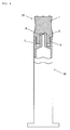
- FIG. 1 is a view illustrating a cap according to the present invention, in which the left half is a side view and the right half is a cross-sectional view.
- FIG. 2 is a plan view of the cap of FIG. 1 .
- the cap 10 according to the present invention is comprised of a rubber-made, solid, circular or polygonal cylindrical, rubber-made base portion 1 and a rubber-made, cylindrical leg portion (which may hereinafter be simply called “leg portion") 2 formed integrally with and extending downwardly from the base portion 1.
- the base portion 1 is formed solid to provide the entire cap 10 with a certain degree of rigidness.
- the base portion 1 depicted in FIG. 1 and FIG. 2 is provided on a top portion thereof with some small convexities 3. These convexities 3 are intended to prevent plural caps 10 from sticking each other at the time of washing, drying or the like in the course of their production. However, these convexities are not essential in the present invention, and constitute a preferred embodiment.
- the leg portion 2 which constitutes the cap 10 according to the present invention, is formed in the shape of a cylinder in continuation with a lower wall of the base portion 1 such that the cylinder is open at a distal end thereof.
- the lower wall 5 of the base portion 1, said lower wall 5 extending to an outer upper part of the outer periphery of the leg portion 2, is located at a position where the base portion 1 is in contact with a top wall of a female luer-lock fitting 7 as shown in FIG. 4
- an outer wall of the leg portion 2, said outer wall downwardly extending from the lower wall 5, is formed in a shape that the outer wall gently bulges out in the form of a circular arc the peak of which is located at substantially the middle between the top and bottom of the outer wall.
- An h/L value greater than the above-described range is not preferred for the automated capping of the cap 10 on the syringe 20, while an h/L value smaller than the above-described range may lead to fall-off of the cap 10 from the syringe 20, for example, upon filling a drug solution.
- the bulged portion may also be in the shape of a ring formed on only a part of the leg portion in the present invention. It is the most important characteristic feature of the present invention that the leg portion is not provided with any helical ridge threadedly engageable with the helical ridge 9 formed on the female luer-lock fitting 7 of the syringe 20 but is provided with the bulged portion or ring which does not threadedly engage the helical ridge 9. Owing to such a construction, it is possible to achieve the object of the present invention that is to automatically cap the cap 10 at high speed on the syringe 20 and to prevent the cap 10 from falling off from the syringe.
- two or more bulged portions or rings can be arranged in the present invention.
- the number of bulged portion (s) or ring (s) can preferably be 1 or 2.
- the position of the ridge of the bulged portion or ring may preferably be around the middle of the outer wall of the leg portion 2 in many instances. This position can be selectively set as desired depending on the shape of the cap 10 and the dimensions and shapes of the female luer-lock fitting 7 and nozzle 8 of the syringe 20.
- the setting of the position of the ridge of the bulged portion or ring on a side close to the base portion 1 is highly effective for the inhibition of a lift of the cap, while the setting of the ridge on the side of the distal end of the leg portion 2 is highly effective for the reduction of the capping resistance of the cap.
- the ridge of the bulged portion or ring may preferably be formed over the entire circumference of the leg portion 2.
- the ridge may be formed intermittently.
- the parts at which no ridge is formed may account preferably for less than 40%, more preferably for less than 20% of the entire circumference of the bulged portion or ring.
- the bulged portion or ring may be formed such that it extends out in a direction perpendicular to the capping direction of the cap 10.
- Such construction is effective in stabilizing the state of engagement between the helical ridge 9 of the female luer-lock fitting 7 and the bulged portion or ring of the cap 10 when the cap 10 is capped on the syringe 20, and hence in reducing a variation in the capping resistance or fall-off resistance of the cap 10.
- an open, distal end portion of the cylindrical leg portion 2 may preferably be formed with an inner diameter ( ⁇ ) greater than the inner diameter ( ⁇ ) of a boundary portion between the cylindrical leg portion 2 and the base portion 1.
- the leg portion 2 may preferably be in a shape that it is somewhat wider at its opening than at the boundary portion.
- the fitting insertion of the cap 10 into the syringe 20 causes the opening to shrink so that upon filling a drug solution, the fall-off of the cap 10 from the syringe 20 can be more preferably prevented owing to the resilience of the leg portion 2 that it tries to recover its original shape.
- the degree of the flare of the opening differs depending on the length of the leg portion 2, the friction resistance between the material of the cap 10 and that of the syringe 20, and the like.
- the opening may have a flare a little smaller than 6/100 which is a taper of the nozzle 8.
- leg portion 2 is fittedly inserted in the space between the nozzle 8 of the syringe 20 and the female luer-lock fitting 7, an internal space of the cylindrical leg portion 2 is configured to surround the nozzle 8, and a downward protuberance 6 is arranged on a ceiling portion inside the leg portion 2 (namely, at the boundary with the base portion 1).
- This protuberance 6 is formed such that it just closes up a bore of the nozzle 8 when the cap 10 is fittedly inserted in the space between the nozzle 8 of the syringe 20 and the female luer-lock fitting 7.
- the inner diameter of the leg portion 2 of the cap 10 according to the present invention is slightly smaller than the outer diameter of the nozzle 8 of the syringe 20.
- the leg portion 2 is caused to flare out so that sealing performance for the nozzle 8 is maintained.
- the outer wall of the leg portion 2 comes into contact under pressure with a cylindrical inner wall of the female luer-lock fitting 7. This pressure contact also takes part in the maintenance of the sealing performance of the cap 10, and moreover, is effective in preventing the cap 10 from falling off.
- the cap 10 according to the present invention can most prominently bring about the advantageous effects of the present invention when the leg portion 2 is coated on at least its outer surface, preferably on its entire surfaces with a fluorinated resin film of approx. 10 to 200 ⁇ m thickness (not shown) concurrently with the molding of the cap 10.
- the inner surface and outer surface of the leg portion 2 may come into contact with a drug solution filled in the syringe 20, so that the fluorinated resin film is laminated to eliminate the possibility of mixing of toxic substances into the drug solution from the rubber-made cap 10 by its contact with the drug solution.
- the fluorinated resin film When the fluorinated resin film is laminated on the surface of the leg portion 2, its lubricity facilitates the automated capping of the cap 10 but renders the cap 10 prone to fall off from the syringe 20 upon filling the drug solution. Owing to the above-described construction of the present invention, the present invention can make the cap 10 free of such a problem upon automated capping and also resistant to fall-off upon filling the drug solution even when the cap 10 is provided with the fluorinated resin film laminated on the leg portion 2.
- the height H of the base portion 1 can be 8 to 20 mm or so (15 mm in the illustrated embodiment)
- the width (diameter) W1 of the base portion 1 can be 8 to 13 mm or so (9.75 mm in the illustrated embodiment)
- the height and diameter of each convexity 3 arranged on the base portion 1 can be 0.2 to 0.3 mm or so and 0.7 to 1.3 mm or so, respectively (0.25 mm and 1.0 mm, respectively, in the illustrated embodiment)
- the depth and size of each recessed part 4 arranged on the base portion 1 can be 0.4 to 0.8 mm or so and 3 to 5 ⁇ 5 to 7 mm or so, respectively (0.6 mm and 4 ⁇ 6.5 mm, respectively, in the illustrated embodiment).
- the length L of the leg portion 2 can be 3 to 10 mm or so (6 mm in the illustrated embodiment), the outer diameter W2 of the leg portion 2 can be 10 to 13 mm (11.2 mm in the illustrated embodiment), the depth of the internal space (nozzle-receiving portion) of the leg portion 2 can be 7 to 10 mm or so (8.5 mm in the illustrated embodiment), the inner diameters ⁇ and ⁇ in the internal space of the leg portion 2 can be 3.0 to 5.0 mm or so and 3.5 to 6. 0 mm, respectively (3.7 mm and 4.1 mm, respectively, in the illustrated embodiment), the h in the leg portion 2 can be 0.5 to 1.
- the thickness of the unillustrated fluorinated resin film coated on the entirety of the leg portion 2 can be 10 to 200 ⁇ m (50 ⁇ m in the illustrated embodiment). It is to be noted that the cap 10 is molded in its entirety of chlorinated butyl rubber.
- the cap 10 according to the present invention can be produced in a similar manner as the caps for the conventional pre-filled syringes.
- the rubber material for use in the production of the cap according to the present invention may preferably be butyl rubber or chlorinated butyl rubber. Including additives, those employed in the production of conventional caps and also of conventional rubber plugs or closures for drugs and medical care are all usable, and no particular limitation is imposed thereon.
- the surfaces of the leg portion of the cap and the content of the syringe can be coated with high molecular weight polyethylene films or films of a resin such as a fluorinated resin similar to the conventional caps and the conventional rubber plugs or closures for drugs and medical care.
- a resin such as a fluorinated resin
- the surfaces of the base portion 1 can also be coated with such films. These films are not applied under the premise of the contact of the surfaces with a drug solution, but are coated to overcome the tackiness which the rubber possesses.
- the films for this purpose can be those of a general-purpose resin such as, for example, polyethylene or polypropylene.
- a cap for a pre-filled syringe which can be surely and automatically capped on a syringe having a female luer-lock fitting and does not fall off upon filling a drug solution.
Landscapes
- Health & Medical Sciences (AREA)
- Vascular Medicine (AREA)
- Engineering & Computer Science (AREA)
- Anesthesiology (AREA)
- Biomedical Technology (AREA)
- Heart & Thoracic Surgery (AREA)
- Hematology (AREA)
- Life Sciences & Earth Sciences (AREA)
- Animal Behavior & Ethology (AREA)
- General Health & Medical Sciences (AREA)
- Public Health (AREA)
- Veterinary Medicine (AREA)
- Infusion, Injection, And Reservoir Apparatuses (AREA)
Applications Claiming Priority (2)
| Application Number | Priority Date | Filing Date | Title |
|---|---|---|---|
| JP2006310750A JP2008125560A (ja) | 2006-11-16 | 2006-11-16 | 注射ノズルキャップ |
| PCT/JP2007/072079 WO2008059863A1 (fr) | 2006-11-16 | 2007-11-14 | Capuchon de buse d'injection |
Publications (3)
| Publication Number | Publication Date |
|---|---|
| EP2092948A1 true EP2092948A1 (de) | 2009-08-26 |
| EP2092948A4 EP2092948A4 (de) | 2013-07-31 |
| EP2092948B1 EP2092948B1 (de) | 2014-05-07 |
Family
ID=39401669
Family Applications (1)
| Application Number | Title | Priority Date | Filing Date |
|---|---|---|---|
| EP07831809.4A Not-in-force EP2092948B1 (de) | 2006-11-16 | 2007-11-14 | Injektionsdüsenkappe |
Country Status (6)
| Country | Link |
|---|---|
| US (1) | US20090287160A1 (de) |
| EP (1) | EP2092948B1 (de) |
| JP (1) | JP2008125560A (de) |
| DK (1) | DK2092948T3 (de) |
| ES (1) | ES2464595T3 (de) |
| WO (1) | WO2008059863A1 (de) |
Cited By (1)
| Publication number | Priority date | Publication date | Assignee | Title |
|---|---|---|---|---|
| US11013865B2 (en) | 2013-10-15 | 2021-05-25 | Becton Dickinson France | Tip cap assembly for closing an injection system |
Families Citing this family (7)
| Publication number | Priority date | Publication date | Assignee | Title |
|---|---|---|---|---|
| JP2013034567A (ja) | 2011-08-05 | 2013-02-21 | Daikyo Seiko Ltd | プラスチック製ノズルキャップ |
| EP2826508A1 (de) * | 2013-07-18 | 2015-01-21 | Becton Dickinson France | Spitzenkappe und Injektionsvorrichtung mit distaler, durch eine Spitzenkappe abgedichteter Spitze |
| JP6268397B2 (ja) * | 2014-03-12 | 2018-01-31 | 住友ゴム工業株式会社 | シリンジ用キャップ |
| US11628288B1 (en) * | 2014-07-14 | 2023-04-18 | Merit Medical Systems, Inc. | Disinfecting cap for needleless injection sites |
| JP6352122B2 (ja) * | 2014-09-11 | 2018-07-04 | テルモ株式会社 | シリンジ用組立体、針付き外筒用シールキャップ、プレフィルドシリンジおよび針付き外筒用シールキャップの製造方法 |
| EP3573699B1 (de) | 2017-01-27 | 2022-08-10 | Merit Medical Systems, Inc. | Desinfizierende luer-kappe und verfahren zur verwendung |
| CN111447963B (zh) * | 2017-12-06 | 2022-09-30 | 住友橡胶工业株式会社 | 前端帽 |
Citations (2)
| Publication number | Priority date | Publication date | Assignee | Title |
|---|---|---|---|---|
| DE817097C (de) * | 1950-01-04 | 1951-10-15 | Erich Dipl-Ing Golde | Verschluss fuer mit Gewinde versehene Flaschen oder Behaelter |
| FR1061943A (fr) * | 1952-05-14 | 1954-04-16 | Bouchon en matière plastique avec évidement intérieur et profil spécial assurant l'élasticité diamétrale |
Family Cites Families (13)
| Publication number | Priority date | Publication date | Assignee | Title |
|---|---|---|---|---|
| US2848130A (en) * | 1953-10-07 | 1958-08-19 | Duo Vent Vacuum Closure Compan | Pressure resistant closures |
| JPS59757U (ja) * | 1982-06-25 | 1984-01-06 | キッコーマン株式会社 | 瓶栓 |
| JPS613240U (ja) * | 1984-06-14 | 1986-01-10 | 日本クラウンコルク株式会社 | 組合せ容器蓋 |
| JPH0717547A (ja) * | 1993-06-30 | 1995-01-20 | Jiyousou Koushitsu Kuroomu:Kk | ゴム栓並びにゴム栓の製造方法及びゴム栓製造用金型 |
| AUPM922394A0 (en) * | 1994-11-03 | 1994-11-24 | Astra Pharmaceuticals Pty Ltd | Plastic syringe with overcap |
| JP3172057B2 (ja) * | 1995-04-05 | 2001-06-04 | 株式会社大協精工 | ラミネートゴム栓 |
| JP3029555B2 (ja) * | 1995-05-29 | 2000-04-04 | 株式会社大協精工 | 医薬用ゴム栓 |
| JP3380705B2 (ja) * | 1997-03-12 | 2003-02-24 | 株式会社大協精工 | 注射器兼容器用密封ゴム栓 |
| US6632199B1 (en) * | 2000-05-23 | 2003-10-14 | Becton Dickinson And Company | Syringe assembly including plastic tip cap |
| JP2002153539A (ja) | 2000-11-16 | 2002-05-28 | Asahi Medical Co Ltd | 医療用具用ルアー栓体及びこれを備える医療用具 |
| JP4535605B2 (ja) * | 2000-12-01 | 2010-09-01 | 住友ゴム工業株式会社 | 医療用ゴム栓 |
| DE10247963A1 (de) * | 2002-10-15 | 2004-05-06 | Transcoject Gesellschaft für medizinische Geräte mbH & Co KG | Membranspritze |
| US20050075611A1 (en) * | 2003-10-01 | 2005-04-07 | Hetzler Kevin G. | Low extractable, thermoplastic syringe and tip cap |
-
2006
- 2006-11-16 JP JP2006310750A patent/JP2008125560A/ja active Pending
-
2007
- 2007-11-14 WO PCT/JP2007/072079 patent/WO2008059863A1/ja active Application Filing
- 2007-11-14 ES ES07831809.4T patent/ES2464595T3/es active Active
- 2007-11-14 EP EP07831809.4A patent/EP2092948B1/de not_active Not-in-force
- 2007-11-14 DK DK07831809.4T patent/DK2092948T3/da active
-
2009
- 2009-05-18 US US12/468,030 patent/US20090287160A1/en not_active Abandoned
Patent Citations (2)
| Publication number | Priority date | Publication date | Assignee | Title |
|---|---|---|---|---|
| DE817097C (de) * | 1950-01-04 | 1951-10-15 | Erich Dipl-Ing Golde | Verschluss fuer mit Gewinde versehene Flaschen oder Behaelter |
| FR1061943A (fr) * | 1952-05-14 | 1954-04-16 | Bouchon en matière plastique avec évidement intérieur et profil spécial assurant l'élasticité diamétrale |
Non-Patent Citations (1)
| Title |
|---|
| See also references of WO2008059863A1 * |
Cited By (1)
| Publication number | Priority date | Publication date | Assignee | Title |
|---|---|---|---|---|
| US11013865B2 (en) | 2013-10-15 | 2021-05-25 | Becton Dickinson France | Tip cap assembly for closing an injection system |
Also Published As
| Publication number | Publication date |
|---|---|
| EP2092948A4 (de) | 2013-07-31 |
| WO2008059863A1 (fr) | 2008-05-22 |
| ES2464595T3 (es) | 2014-06-03 |
| DK2092948T3 (da) | 2014-06-23 |
| US20090287160A1 (en) | 2009-11-19 |
| JP2008125560A (ja) | 2008-06-05 |
| EP2092948B1 (de) | 2014-05-07 |
Similar Documents
| Publication | Publication Date | Title |
|---|---|---|
| EP2092948B1 (de) | Injektionsdüsenkappe | |
| CA2495214C (en) | Closure system for a vial, vial, method of closing and filling a vial and stand for a vial | |
| US6821268B2 (en) | Tamper evident overap of a container | |
| US5409125A (en) | Unit dose container | |
| EP3057633B1 (de) | Spitzenkappenanordnung zum verschliessen eines injektionssystems | |
| US6520935B1 (en) | Syringe and tip cap assembly | |
| US6957745B2 (en) | Transfer set | |
| EP1192965B1 (de) | Spritzenendstückkappe | |
| US20010001116A1 (en) | Container cap assembly having an enclosed penetrator | |
| CN107596504B (zh) | 末端帽组件、药物注射系统和制造该药物注射系统的方法 | |
| JP2000157630A (ja) | 注射ノズルキャップ | |
| CA2469034A1 (en) | Synthetic resin bottle and preform mold | |
| EP3393572B1 (de) | Anschlusskappe für nadellose spritze und behälter | |
| WO1991008729A1 (en) | Unit dose container | |
| EP3753544B1 (de) | Phiolenanordnung mit luer-anschluss | |
| CN215134908U (zh) | 一种预灌封注射器用覆膜护帽 | |
| JP2006006791A (ja) | 容器兼用注射器の注射ノズル用密封ゴム栓 | |
| JPH0626876U (ja) | 医薬品用ゴム栓 | |
| AU3434002A (en) | Container cap assembly having an enclosed penetrator | |
| JP2014094223A (ja) | 医療用キャップ |
Legal Events
| Date | Code | Title | Description |
|---|---|---|---|
| PUAI | Public reference made under article 153(3) epc to a published international application that has entered the european phase |
Free format text: ORIGINAL CODE: 0009012 |
|
| 17P | Request for examination filed |
Effective date: 20090429 |
|
| AK | Designated contracting states |
Kind code of ref document: A1 Designated state(s): AT BE BG CH CY CZ DE DK EE ES FI FR GB GR HU IE IS IT LI LT LU LV MC MT NL PL PT RO SE SI SK TR |
|
| DAX | Request for extension of the european patent (deleted) | ||
| A4 | Supplementary search report drawn up and despatched |
Effective date: 20130628 |
|
| RIC1 | Information provided on ipc code assigned before grant |
Ipc: A61M 5/31 20060101AFI20130624BHEP |
|
| GRAP | Despatch of communication of intention to grant a patent |
Free format text: ORIGINAL CODE: EPIDOSNIGR1 |
|
| INTG | Intention to grant announced |
Effective date: 20131127 |
|
| GRAS | Grant fee paid |
Free format text: ORIGINAL CODE: EPIDOSNIGR3 |
|
| GRAA | (expected) grant |
Free format text: ORIGINAL CODE: 0009210 |
|
| AK | Designated contracting states |
Kind code of ref document: B1 Designated state(s): AT BE BG CH CY CZ DE DK EE ES FI FR GB GR HU IE IS IT LI LT LU LV MC MT NL PL PT RO SE SI SK TR |
|
| REG | Reference to a national code |
Ref country code: GB Ref legal event code: FG4D |
|
| REG | Reference to a national code |
Ref country code: AT Ref legal event code: REF Ref document number: 666115 Country of ref document: AT Kind code of ref document: T Effective date: 20140515 |
|
| REG | Reference to a national code |
Ref country code: ES Ref legal event code: FG2A Ref document number: 2464595 Country of ref document: ES Kind code of ref document: T3 Effective date: 20140603 |
|
| REG | Reference to a national code |
Ref country code: IE Ref legal event code: FG4D |
|
| REG | Reference to a national code |
Ref country code: DE Ref legal event code: R096 Ref document number: 602007036596 Country of ref document: DE Effective date: 20140612 |
|
| REG | Reference to a national code |
Ref country code: CH Ref legal event code: NV Representative=s name: BOHEST AG, CH |
|
| REG | Reference to a national code |
Ref country code: DK Ref legal event code: T3 Effective date: 20140620 |
|
| REG | Reference to a national code |
Ref country code: CH Ref legal event code: PCAR Free format text: NEW ADDRESS: HOLBEINSTRASSE 36-38, 4051 BASEL (CH) |
|
| REG | Reference to a national code |
Ref country code: SE Ref legal event code: TRGR |
|
| REG | Reference to a national code |
Ref country code: AT Ref legal event code: MK05 Ref document number: 666115 Country of ref document: AT Kind code of ref document: T Effective date: 20140507 |
|
| REG | Reference to a national code |
Ref country code: NL Ref legal event code: VDEP Effective date: 20140507 |
|
| REG | Reference to a national code |
Ref country code: LT Ref legal event code: MG4D |
|
| PG25 | Lapsed in a contracting state [announced via postgrant information from national office to epo] |
Ref country code: IS Free format text: LAPSE BECAUSE OF FAILURE TO SUBMIT A TRANSLATION OF THE DESCRIPTION OR TO PAY THE FEE WITHIN THE PRESCRIBED TIME-LIMIT Effective date: 20140907 Ref country code: CY Free format text: LAPSE BECAUSE OF FAILURE TO SUBMIT A TRANSLATION OF THE DESCRIPTION OR TO PAY THE FEE WITHIN THE PRESCRIBED TIME-LIMIT Effective date: 20140507 Ref country code: GR Free format text: LAPSE BECAUSE OF FAILURE TO SUBMIT A TRANSLATION OF THE DESCRIPTION OR TO PAY THE FEE WITHIN THE PRESCRIBED TIME-LIMIT Effective date: 20140808 Ref country code: FI Free format text: LAPSE BECAUSE OF FAILURE TO SUBMIT A TRANSLATION OF THE DESCRIPTION OR TO PAY THE FEE WITHIN THE PRESCRIBED TIME-LIMIT Effective date: 20140507 Ref country code: LT Free format text: LAPSE BECAUSE OF FAILURE TO SUBMIT A TRANSLATION OF THE DESCRIPTION OR TO PAY THE FEE WITHIN THE PRESCRIBED TIME-LIMIT Effective date: 20140507 |
|
| PG25 | Lapsed in a contracting state [announced via postgrant information from national office to epo] |
Ref country code: LV Free format text: LAPSE BECAUSE OF FAILURE TO SUBMIT A TRANSLATION OF THE DESCRIPTION OR TO PAY THE FEE WITHIN THE PRESCRIBED TIME-LIMIT Effective date: 20140507 Ref country code: AT Free format text: LAPSE BECAUSE OF FAILURE TO SUBMIT A TRANSLATION OF THE DESCRIPTION OR TO PAY THE FEE WITHIN THE PRESCRIBED TIME-LIMIT Effective date: 20140507 Ref country code: PL Free format text: LAPSE BECAUSE OF FAILURE TO SUBMIT A TRANSLATION OF THE DESCRIPTION OR TO PAY THE FEE WITHIN THE PRESCRIBED TIME-LIMIT Effective date: 20140507 |
|
| PG25 | Lapsed in a contracting state [announced via postgrant information from national office to epo] |
Ref country code: PT Free format text: LAPSE BECAUSE OF FAILURE TO SUBMIT A TRANSLATION OF THE DESCRIPTION OR TO PAY THE FEE WITHIN THE PRESCRIBED TIME-LIMIT Effective date: 20140908 |
|
| PG25 | Lapsed in a contracting state [announced via postgrant information from national office to epo] |
Ref country code: RO Free format text: LAPSE BECAUSE OF FAILURE TO SUBMIT A TRANSLATION OF THE DESCRIPTION OR TO PAY THE FEE WITHIN THE PRESCRIBED TIME-LIMIT Effective date: 20140507 Ref country code: EE Free format text: LAPSE BECAUSE OF FAILURE TO SUBMIT A TRANSLATION OF THE DESCRIPTION OR TO PAY THE FEE WITHIN THE PRESCRIBED TIME-LIMIT Effective date: 20140507 Ref country code: CZ Free format text: LAPSE BECAUSE OF FAILURE TO SUBMIT A TRANSLATION OF THE DESCRIPTION OR TO PAY THE FEE WITHIN THE PRESCRIBED TIME-LIMIT Effective date: 20140507 Ref country code: SK Free format text: LAPSE BECAUSE OF FAILURE TO SUBMIT A TRANSLATION OF THE DESCRIPTION OR TO PAY THE FEE WITHIN THE PRESCRIBED TIME-LIMIT Effective date: 20140507 |
|
| REG | Reference to a national code |
Ref country code: DE Ref legal event code: R097 Ref document number: 602007036596 Country of ref document: DE |
|
| PG25 | Lapsed in a contracting state [announced via postgrant information from national office to epo] |
Ref country code: NL Free format text: LAPSE BECAUSE OF FAILURE TO SUBMIT A TRANSLATION OF THE DESCRIPTION OR TO PAY THE FEE WITHIN THE PRESCRIBED TIME-LIMIT Effective date: 20140507 |
|
| PLBE | No opposition filed within time limit |
Free format text: ORIGINAL CODE: 0009261 |
|
| STAA | Information on the status of an ep patent application or granted ep patent |
Free format text: STATUS: NO OPPOSITION FILED WITHIN TIME LIMIT |
|
| 26N | No opposition filed |
Effective date: 20150210 |
|
| REG | Reference to a national code |
Ref country code: DE Ref legal event code: R097 Ref document number: 602007036596 Country of ref document: DE Effective date: 20150210 |
|
| PG25 | Lapsed in a contracting state [announced via postgrant information from national office to epo] |
Ref country code: MC Free format text: LAPSE BECAUSE OF FAILURE TO SUBMIT A TRANSLATION OF THE DESCRIPTION OR TO PAY THE FEE WITHIN THE PRESCRIBED TIME-LIMIT Effective date: 20140507 Ref country code: LU Free format text: LAPSE BECAUSE OF FAILURE TO SUBMIT A TRANSLATION OF THE DESCRIPTION OR TO PAY THE FEE WITHIN THE PRESCRIBED TIME-LIMIT Effective date: 20141114 |
|
| PG25 | Lapsed in a contracting state [announced via postgrant information from national office to epo] |
Ref country code: SI Free format text: LAPSE BECAUSE OF FAILURE TO SUBMIT A TRANSLATION OF THE DESCRIPTION OR TO PAY THE FEE WITHIN THE PRESCRIBED TIME-LIMIT Effective date: 20140507 |
|
| REG | Reference to a national code |
Ref country code: FR Ref legal event code: PLFP Year of fee payment: 9 |
|
| PG25 | Lapsed in a contracting state [announced via postgrant information from national office to epo] |
Ref country code: BG Free format text: LAPSE BECAUSE OF FAILURE TO SUBMIT A TRANSLATION OF THE DESCRIPTION OR TO PAY THE FEE WITHIN THE PRESCRIBED TIME-LIMIT Effective date: 20140507 |
|
| PG25 | Lapsed in a contracting state [announced via postgrant information from national office to epo] |
Ref country code: MT Free format text: LAPSE BECAUSE OF FAILURE TO SUBMIT A TRANSLATION OF THE DESCRIPTION OR TO PAY THE FEE WITHIN THE PRESCRIBED TIME-LIMIT Effective date: 20140507 Ref country code: HU Free format text: LAPSE BECAUSE OF FAILURE TO SUBMIT A TRANSLATION OF THE DESCRIPTION OR TO PAY THE FEE WITHIN THE PRESCRIBED TIME-LIMIT; INVALID AB INITIO Effective date: 20071114 Ref country code: TR Free format text: LAPSE BECAUSE OF FAILURE TO SUBMIT A TRANSLATION OF THE DESCRIPTION OR TO PAY THE FEE WITHIN THE PRESCRIBED TIME-LIMIT Effective date: 20140507 |
|
| REG | Reference to a national code |
Ref country code: FR Ref legal event code: PLFP Year of fee payment: 10 |
|
| REG | Reference to a national code |
Ref country code: FR Ref legal event code: PLFP Year of fee payment: 11 |
|
| REG | Reference to a national code |
Ref country code: FR Ref legal event code: PLFP Year of fee payment: 12 |
|
| PGFP | Annual fee paid to national office [announced via postgrant information from national office to epo] |
Ref country code: DK Payment date: 20181109 Year of fee payment: 12 Ref country code: DE Payment date: 20181030 Year of fee payment: 12 Ref country code: IE Payment date: 20181109 Year of fee payment: 12 Ref country code: SE Payment date: 20181113 Year of fee payment: 12 |
|
| PGFP | Annual fee paid to national office [announced via postgrant information from national office to epo] |
Ref country code: BE Payment date: 20181015 Year of fee payment: 12 Ref country code: FR Payment date: 20181011 Year of fee payment: 12 Ref country code: GB Payment date: 20181114 Year of fee payment: 12 Ref country code: CH Payment date: 20181115 Year of fee payment: 12 Ref country code: ES Payment date: 20181204 Year of fee payment: 12 Ref country code: IT Payment date: 20181122 Year of fee payment: 12 |
|
| REG | Reference to a national code |
Ref country code: DE Ref legal event code: R119 Ref document number: 602007036596 Country of ref document: DE |
|
| REG | Reference to a national code |
Ref country code: DK Ref legal event code: EBP Effective date: 20191130 |
|
| REG | Reference to a national code |
Ref country code: SE Ref legal event code: EUG Ref country code: CH Ref legal event code: PL |
|
| PG25 | Lapsed in a contracting state [announced via postgrant information from national office to epo] |
Ref country code: LI Free format text: LAPSE BECAUSE OF NON-PAYMENT OF DUE FEES Effective date: 20191130 Ref country code: CH Free format text: LAPSE BECAUSE OF NON-PAYMENT OF DUE FEES Effective date: 20191130 |
|
| REG | Reference to a national code |
Ref country code: BE Ref legal event code: MM Effective date: 20191130 |
|
| PG25 | Lapsed in a contracting state [announced via postgrant information from national office to epo] |
Ref country code: SE Free format text: LAPSE BECAUSE OF NON-PAYMENT OF DUE FEES Effective date: 20191115 |
|
| GBPC | Gb: european patent ceased through non-payment of renewal fee |
Effective date: 20191114 |
|
| PG25 | Lapsed in a contracting state [announced via postgrant information from national office to epo] |
Ref country code: GB Free format text: LAPSE BECAUSE OF NON-PAYMENT OF DUE FEES Effective date: 20191114 Ref country code: DK Free format text: LAPSE BECAUSE OF NON-PAYMENT OF DUE FEES Effective date: 20191130 Ref country code: IT Free format text: LAPSE BECAUSE OF NON-PAYMENT OF DUE FEES Effective date: 20191114 Ref country code: FR Free format text: LAPSE BECAUSE OF NON-PAYMENT OF DUE FEES Effective date: 20191130 Ref country code: DE Free format text: LAPSE BECAUSE OF NON-PAYMENT OF DUE FEES Effective date: 20200603 Ref country code: IE Free format text: LAPSE BECAUSE OF NON-PAYMENT OF DUE FEES Effective date: 20191114 |
|
| PG25 | Lapsed in a contracting state [announced via postgrant information from national office to epo] |
Ref country code: BE Free format text: LAPSE BECAUSE OF NON-PAYMENT OF DUE FEES Effective date: 20191130 |
|
| REG | Reference to a national code |
Ref country code: ES Ref legal event code: FD2A Effective date: 20210528 |
|
| PG25 | Lapsed in a contracting state [announced via postgrant information from national office to epo] |
Ref country code: ES Free format text: LAPSE BECAUSE OF NON-PAYMENT OF DUE FEES Effective date: 20191115 |