EP2091706B1 - Apparatus for scattering fibrous material, e.g. chips - Google Patents
Apparatus for scattering fibrous material, e.g. chips Download PDFInfo
- Publication number
- EP2091706B1 EP2091706B1 EP07823233A EP07823233A EP2091706B1 EP 2091706 B1 EP2091706 B1 EP 2091706B1 EP 07823233 A EP07823233 A EP 07823233A EP 07823233 A EP07823233 A EP 07823233A EP 2091706 B1 EP2091706 B1 EP 2091706B1
- Authority
- EP
- European Patent Office
- Prior art keywords
- scattering
- discs
- elements
- chips
- chamber
- Prior art date
- Legal status (The legal status is an assumption and is not a legal conclusion. Google has not performed a legal analysis and makes no representation as to the accuracy of the status listed.)
- Active
Links
- 239000002657 fibrous material Substances 0.000 title claims abstract description 4
- 239000002245 particle Substances 0.000 claims abstract description 23
- 238000003892 spreading Methods 0.000 claims abstract description 19
- 238000000034 method Methods 0.000 claims abstract description 8
- 239000000463 material Substances 0.000 claims abstract description 7
- 230000003749 cleanliness Effects 0.000 claims 3
- 238000007664 blowing Methods 0.000 description 3
- 238000004140 cleaning Methods 0.000 description 3
- 238000010276 construction Methods 0.000 description 3
- 239000011236 particulate material Substances 0.000 description 3
- 101100495256 Caenorhabditis elegans mat-3 gene Proteins 0.000 description 2
- 238000003491 array Methods 0.000 description 2
- 239000011230 binding agent Substances 0.000 description 2
- 230000015572 biosynthetic process Effects 0.000 description 2
- 230000001627 detrimental effect Effects 0.000 description 2
- 230000000694 effects Effects 0.000 description 2
- 238000012423 maintenance Methods 0.000 description 2
- 239000003973 paint Substances 0.000 description 2
- 238000009966 trimming Methods 0.000 description 2
- 239000002023 wood Substances 0.000 description 2
- 239000011248 coating agent Substances 0.000 description 1
- 238000000576 coating method Methods 0.000 description 1
- 238000005520 cutting process Methods 0.000 description 1
- 230000007547 defect Effects 0.000 description 1
- 230000000593 degrading effect Effects 0.000 description 1
- 230000003292 diminished effect Effects 0.000 description 1
- 238000010017 direct printing Methods 0.000 description 1
- 239000000428 dust Substances 0.000 description 1
- 239000000835 fiber Substances 0.000 description 1
- 230000005484 gravity Effects 0.000 description 1
- 230000001788 irregular Effects 0.000 description 1
- 238000004519 manufacturing process Methods 0.000 description 1
- 238000007639 printing Methods 0.000 description 1
- 238000000926 separation method Methods 0.000 description 1
- 238000004381 surface treatment Methods 0.000 description 1
Images


Classifications
-
- B—PERFORMING OPERATIONS; TRANSPORTING
- B27—WORKING OR PRESERVING WOOD OR SIMILAR MATERIAL; NAILING OR STAPLING MACHINES IN GENERAL
- B27N—MANUFACTURE BY DRY PROCESSES OF ARTICLES, WITH OR WITHOUT ORGANIC BINDING AGENTS, MADE FROM PARTICLES OR FIBRES CONSISTING OF WOOD OR OTHER LIGNOCELLULOSIC OR LIKE ORGANIC MATERIAL
- B27N3/00—Manufacture of substantially flat articles, e.g. boards, from particles or fibres
- B27N3/08—Moulding or pressing
- B27N3/10—Moulding of mats
- B27N3/14—Distributing or orienting the particles or fibres
-
- B—PERFORMING OPERATIONS; TRANSPORTING
- B07—SEPARATING SOLIDS FROM SOLIDS; SORTING
- B07B—SEPARATING SOLIDS FROM SOLIDS BY SIEVING, SCREENING, SIFTING OR BY USING GAS CURRENTS; SEPARATING BY OTHER DRY METHODS APPLICABLE TO BULK MATERIAL, e.g. LOOSE ARTICLES FIT TO BE HANDLED LIKE BULK MATERIAL
- B07B4/00—Separating solids from solids by subjecting their mixture to gas currents
-
- B—PERFORMING OPERATIONS; TRANSPORTING
- B08—CLEANING
- B08B—CLEANING IN GENERAL; PREVENTION OF FOULING IN GENERAL
- B08B7/00—Cleaning by methods not provided for in a single other subclass or a single group in this subclass
- B08B7/02—Cleaning by methods not provided for in a single other subclass or a single group in this subclass by distortion, beating, or vibration of the surface to be cleaned
-
- B—PERFORMING OPERATIONS; TRANSPORTING
- B65—CONVEYING; PACKING; STORING; HANDLING THIN OR FILAMENTARY MATERIAL
- B65G—TRANSPORT OR STORAGE DEVICES, e.g. CONVEYORS FOR LOADING OR TIPPING, SHOP CONVEYOR SYSTEMS OR PNEUMATIC TUBE CONVEYORS
- B65G69/00—Auxiliary measures taken, or devices used, in connection with loading or unloading
- B65G69/04—Spreading out the materials conveyed over the whole surface to be loaded; Trimming heaps of loose materials
Definitions
- the present invention relates to an apparatus for scattering fibrous material, e.g., chips, said apparatus serving to spread chips using either a throw or air-jet spreading method to form a mat of chips onto a moving band conveyor or the like, whereby the scattering process avails a gas flow, such as air flow, for instance; the apparatus having a scattering chamber mounted above the band conveyor or the like.
- Scattering chips by rollers is basically known from patent publication FI-90746 , wherein is disclosed an apparatus for spreading fibers or chips together with a binder into a mat onto a forming band conveyor, said apparatus comprising one array of rollers comprising at least three mutually parallel rollers, whereby the interroller spacings are adapted adjustable.
- An air flow is adapted to pass between the roller array and the band conveyor by means of air suction or using a combination air blow and suction.
- roller scattering is characterized by a good accuracy of scattering (i.e., small variations of basis weight of the mat) inasmuch as the classification of the chips is chiefly performed mechanically by means of the roller array rather than with the help of an air flow as in air-jet spreading.
- the control of air flow patterns is particularly problematic. The air flow readily tends to become excessively turbulent thus degrading the accuracy of scattering (hence, the quality of scattering), because strong turbulence deviates the chip particles in an uncontrollable fashion, particularly in the cross direction of the particle mat.
- the surface quality of particle board must fulfill increasingly higher specifications in certain surface treatment applications (particularly those aiming to cut costs).
- One such application is so-called "direct printing” wherein onto the surface of the board that is pretreated with a thin primer layer is printed, e.g., a wood grain imitation pattern directly using a multicolor printing method.
- the coat layers or paint layers applied onto particle boards are today preferably made thinner than previously. Board types suited for such coat application must have an extremely dense surface texture and be comprised of particles so fine that all the chips can typically pass through screen openings of, e.g., 1 mm square and, furthermore, of this chips typically 70 %, for instance, can pass screen openings of 0.5 mm square.
- a particularly critical requirement is that such particles to spread must be sufficiently thin, e.g., max. 0.3 mm thick.
- the demand for chip thinness is in turn linked thereto that a particle possibly detached from the board surface during sanding or, e.g., edge trimming, may not leave an excessively deep dent that later could become visible as, e.g., a surface defect after the application of a thin coat or as a disturbing ragged edge after trimming a coated board by a saw.
- a thin chip that advantageously has a leaf- or fiber-like shape also reduces the porosity of the board surface thus, e.g., cutting down paint consumption during coating and improving the strength of the glue-to-chip bond, whereby the separation of chips is diminished.
- a thick chip having, e.g., a cubical shape is inferior in this respect.
- the irregular turbulence of air flows that degrades the accuracy of scattering is accentuated in conventional spreading by air jets which requires relatively high air plenums (typically higher than 2 m) together with air flow velocities typically faster than those employed in roller array scattering, and further, particularly, the use of active blowing at the feed end of chips in order to attain sufficient classification.
- the air-jet plenums must also be complemented with screens serving to damp turbulence of air flow. Such screens are clumsy to use, cause extra costs and are readily plugged as they must be placed in a dusty space. Due to dust generation by the active air jet blowing, the maintenance need of an air-jet spreading system is extensive as compared with roller array scattering. The production line must be stopped frequently for cleaning the air-jet nozzles and screens in order to restore the scattering accuracy to a reasonably good level.
- the drop height of chips in roller array scattering must be increased case-by-case so much that a sufficiently large fraction of thin chips can be classified apart and, at the right moment, caused to drop onto a desired area of the particle mat.
- Increasing the scattering chamber height promotes the turbulence of the air flow being sucked/blown into the chamber, whereby the accuracy of scattering is degraded.
- a roller array scattering apparatus wherein an attempt is made to improve the accuracy of scattering with the help of an element which is placed in front of the air inlet opening located at the exit end of the roller array in the travel direction of the wood chips in order to homogenize the air inlet flow pattern.
- the flow-homogenizing element comprises, e.g., a drilled plate, screen, honeycomb structure or a tangential blower or the like capable of producing a substantially laminar air flow pattern, or a combination of any of these.
- Such an arrangement has been found to reduce lateral turbulence, particularly in the vicinity of the flow-homogenizing element.
- its effect cannot be extended over the entire volume of the scattering chamber, but instead, the transverse turbulence more remotely from the homogenizing element increases in a disturbing fashion.
- the scattering chamber height is preferably maximized to improve the classification of particles.
- a higher scattering chamber invokes detrimental lateral turbulence, whereby the cross-machine profile of the particle mat cannot be made sufficiently homogeneous due to the uncontrolled landing of the particles onto the conveyor across its cross-machine width.
- Turbulence is primarily invoked by the impingement of the air flow on the material flow. Obviously, turbulence increases when the scattering chamber is made higher and the air flow velocity is increased.
- the problems are solved by virtue of the present invention characterized in that, to prevent lateral turbulence, the volume of the scattering chamber's length wherein the major portion of the material being scattered falls onto the band conveyor or the like is at least partially divided into smaller subspaces adjacent to each other in the cross-machine direction by substantially thin plate-like elements set apart from each other in cross-machine direction at a spacing substantially larger than the particle size of the material being scattered.
- a preferred embodiment of the apparatus according to the invention is characterized in that the substantially thin plate-like elements have a length substantially equal to that of the scattering chamber and a height extending over a portion of the scattering chamber height.
- Another preferred embodiment of the apparatus according to the invention is characterized in that in the longitudinal direction of the scattering chamber are adapted a plurality of shorter plates in succession and in parallel so aligned as to run substantially in vertical planes in the longitudinal direction of the chamber.
- a still another preferred embodiment of the apparatus according to the invention is characterized in that in the longitudinal direction of the scattering chamber are adapted a plurality of shorter plates in succession and in parallel so aligned as to be substantially staggered in their vertical planes in the longitudinal direction of the chamber.
- Division of the scattering chamber in its longitudinal direction into plural narrow subspaces prevents the detrimental cross-machine turbulence. Resultingly, particles can fall freely down but cannot deviate during the fall in the lateral direction, whereby the density profile of the particle mat in the cross-machine direction obviously becomes more homogeneous than in prior-art systems. Due to the extreme thinness of the compartmentalizing plates/discs, they will not cause lateral deviation of the chips in scattering.
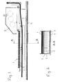
- FIG. 1 an apparatus for scattering chips by way of using a roller array 1 for scattering while the classification of chips is enhanced by air flow.
- the air flow can be implemented by suction and/or blowing.
- One such scattering roller array is disclosed in FI Pat. No. 90746 .
- the chips are fed from the scattering chamber 2 in a conventional fashion onto the roller array 1, wherefrom the chips fall onto a band conveyor 4 so as to form a particle mat 3.
- the travel direction of the band conveyor is denoted by an arrow.
- Between the band conveyor 4 and the roller array 1 is situated a volume called scattering space.
- the scattering space discussed in this invention may as well be situated, e.g., between two roller arrays or does not necessarily need a roller array at all.
- An example of such scattering space is formed in an air-jet spreading chamber ( FIGS. 12 and 13 ).
- an apparatus 5 for preventing turbulence, particularly lateral turbulence, in the inflowing air and particulate material being scattered.
- the scattering space is divided in its longitudinal direction (air flow direction) into plural smaller subspaces.
- the apparatus is provided with thin, plate-like, elongated elements 6 attached to transverse bars 7.
- the thickness of the plate-like elements 6 can be in the order of 1 mm, for instance.
- the plate elements prevent drift of the air flow and chips in the lateral direction, whereby the chips fall smoothly so as to form a homogeneous particle mat 3.
- the air flow through the scattering chamber is indicated by a thick arrow 8.
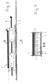
- FIGS. 3 and 4 is shown an apparatus 5 for dividing the scattering space in its longitudinal direction into plural subspaces, whereby in this apparatus the thin plate-like elements do not have a length extending over the entire length of the scattering space, but instead, are made shorter with a length of about 1/3 of the chamber length in the illustrated embodiment.
- these plate elements of a given longitudinal vane are staggered so that the plate in the center position is laterally shifted in regard with the preceding and succeeding plate.
- the purpose of the longitudinally staggered disposition is to avoid the formation of tracks on the laid mat of particulate material.
- arrow 8 is drawn in an intermitted fashion.
- FIGS. 5 and 6 is shown an embodiment similar to that of FIGS. 3 and 4 , the only difference being in the placement of the plate-like elements of a longitudinal vane that are here aligned in line thus allowing the air flow (arrow 8) to travel directly.
- FIG. 7 is shown an apparatus having a construction different from those described above. Lateral turbulence in the scattering space of this embodiment is prevented with the help of thin disc-like elements 9 by means of which the scattering space is divided in its longitudinal direction into narrower subspaces.
- the discs 9 are mounted on shafts 10 substantially equispaced in the cross-machine direction of the scattering space. In the longitudinal direction of the scattering space, the shafts are also substantially equispaced.
- FIG. 7 is shown an embodiment wherein the discs mounted on the successive shafts are spaced tightly close to each other thus allowing a simple removal of a shaft during maintenance.
- FIGS. 8 and 9 are shown sectional views of alternative embodiments taken along line D-D in FIG. 7 .
- the discs are shown aligned in line, whereby the longitudinal air flow channels of the scattering space are straight in a top view.
- FIG. 9 respectively is shown an embodiment having the discs 9 mounted on the successive shafts laterally stairwise staggered, whereby the longitudinal air flow channels become meandering in lieu of being straight.
- the discs 9 are advantageously made very thin with a thickness of about 1 mm, whereby they cannot interfere with outcome of scattering. Should the discs be made thicker, the density of the particle mat forming right below them would become different from the average thickness of the mat.
- the mutual spacing of discs 9 is set substantially wider than the largest dimension of the scattered chips, whereby the discs cannot essentially affect the alignment of the particles landing on the mat.
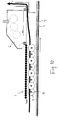
- FIG. 10 is shown an embodiment having the discs aligned not only in a staggered fashion but also in a partially interdigitated. In other details this construction is similar to that shown in FIGS. 7-9 .
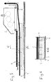
- FIG. 11 is shown an embodiment similar to that of FIG. 7 , now complemented in the space between conveyor 4 and roller array 1 at the exit end of roller array 1 with a flow-homogenizing element 11 disclosed in FI Pat. Appl. 2006 0437 additionally having air blow adapted thereto.
- FIG. 12 is shown an embodiment having the invention adapted to air-jet spreading alone.
- shafts 10 with discs 9 mounted thereon advantageously across the entire width of the air-jet spreading chamber.
- the number of shafts and discs can be varied freely as required in a particular application. Also their placement in the air-jet spreading chamber may be varied.
- FIG. 13 is shown an alternative embodiment for use in an air-jet spreading chamber.
- the apparatus preventing lateral turbulence comprises plate-like elements 12 whose number and placement may be implemented in a fashion suited for a particular application.
- the elements serving to prevent lateral turbulence must obviously be kept sufficiently clean to avoid formation of undesirable clump that may fall onto the mat of particles and like disturbances.
- Cleaning the elements may be arranged, e.g., by complementing the elements with a vibrator or making them otherwise actuatable.
- the discs 9 can be made rotatable.
- separate cleaning means may be adapted to the apparatus.
Landscapes
- Life Sciences & Earth Sciences (AREA)
- Engineering & Computer Science (AREA)
- Manufacturing & Machinery (AREA)
- Wood Science & Technology (AREA)
- Forests & Forestry (AREA)
- Dry Formation Of Fiberboard And The Like (AREA)
- Drying Of Solid Materials (AREA)
- Combined Means For Separation Of Solids (AREA)
- Disintegrating Or Milling (AREA)
- Fertilizers (AREA)
- Filling Or Emptying Of Bunkers, Hoppers, And Tanks (AREA)
- Artificial Filaments (AREA)
- Nozzles (AREA)
- Preliminary Treatment Of Fibers (AREA)
Applications Claiming Priority (2)
| Application Number | Priority Date | Filing Date | Title |
|---|---|---|---|
| FI20061067A FI122575B (fi) | 2006-12-04 | 2006-12-04 | Laitteisto kuitujen, kuten lastujen sirottelemiseksi |
| PCT/FI2007/050596 WO2008068378A1 (en) | 2006-12-04 | 2007-11-07 | Apparatus for scattering fibrous material, e.g. chips |
Publications (3)
| Publication Number | Publication Date |
|---|---|
| EP2091706A1 EP2091706A1 (en) | 2009-08-26 |
| EP2091706A4 EP2091706A4 (en) | 2011-01-05 |
| EP2091706B1 true EP2091706B1 (en) | 2012-03-28 |
Family
ID=37623704
Family Applications (1)
| Application Number | Title | Priority Date | Filing Date |
|---|---|---|---|
| EP07823233A Active EP2091706B1 (en) | 2006-12-04 | 2007-11-07 | Apparatus for scattering fibrous material, e.g. chips |
Country Status (8)
| Country | Link |
|---|---|
| US (1) | US8241025B2 (fi) |
| EP (1) | EP2091706B1 (fi) |
| CN (1) | CN101616779B (fi) |
| AT (1) | ATE551129T1 (fi) |
| CA (1) | CA2670946C (fi) |
| FI (1) | FI122575B (fi) |
| RU (1) | RU2452617C2 (fi) |
| WO (1) | WO2008068378A1 (fi) |
Families Citing this family (9)
| Publication number | Priority date | Publication date | Assignee | Title |
|---|---|---|---|---|
| DE102009047125A1 (de) * | 2009-11-25 | 2011-05-26 | Dieffenbacher Gmbh + Co. Kg | Anlage und Verfahren zur Formung einer Streugutmatte aus Streugut auf einem Formband im Zuge der Herstellung von Werkstoffplatten |
| EP2626179B1 (en) | 2012-02-09 | 2015-05-13 | IKEA Supply AG | Apparatus and method for scattering particles in a particle board production |
| WO2014110663A1 (en) * | 2013-01-18 | 2014-07-24 | Ainsworth Lumber Co. Ltd. | Strand orientation system and method |
| FI125434B (fi) * | 2013-12-20 | 2015-10-15 | Dieffenbacher Panelboard Oy | Menetelmä ja laitteisto kuitujen, kuten lastujen sirottelemiseksi |
| FI125435B (fi) * | 2013-12-20 | 2015-10-15 | Dieffenbacher Panelboard Oy | Menetelmä ja laitteisto kuitujen, kuten lastujen sirottelemiseksi |
| CN204687853U (zh) * | 2015-03-20 | 2015-10-07 | 京东方科技集团股份有限公司 | 一种车载显示系统和汽车 |
| JP3215714U (ja) * | 2015-04-10 | 2018-04-12 | メイフェア フェアメーゲンスフェアヴァルテゥングス エスエー | パネルを製造するための装置と、この装置で製造されるパネル、この装置に備えらえる散布ヘッド及び外層散布ヘッド |
| CN112299059A (zh) * | 2020-11-18 | 2021-02-02 | 武汉轻工大学 | 方形粮仓平摊装置 |
| CN113386237B (zh) * | 2021-05-18 | 2025-04-11 | 广西高峰桂山人造板有限公司 | 用于刨花板生产的铺装箱 |
Family Cites Families (23)
| Publication number | Priority date | Publication date | Assignee | Title |
|---|---|---|---|---|
| US3115431A (en) * | 1959-09-10 | 1963-12-24 | Abitibi Power & Paper Co | Method and apparatus for making oriented wood particle board |
| US3202743A (en) * | 1961-09-06 | 1965-08-24 | Elmendorf Armin | Method of forming a composite panel |
| US3807931A (en) * | 1971-08-20 | 1974-04-30 | Potlatch Corp | Apparatus for orienting wood strands |
| US4058201A (en) | 1974-12-20 | 1977-11-15 | Elmendorf Research, Inc. | Method and apparatus for orienting wood strands into parallelism |
| DE2851779C2 (de) * | 1978-11-30 | 1984-05-30 | G. Siempelkamp Gmbh & Co, 4150 Krefeld | Streuvorrichtung |
| DE3018683C2 (de) * | 1980-05-16 | 1986-05-15 | Carl Schenck Ag, 6100 Darmstadt | Vorrichtung zum Ausrichten von Spänen in eine Vorzugsrichtung bei der Herstellung von Spanplatten |
| US4494919A (en) * | 1982-09-20 | 1985-01-22 | Macmillan Bloedel Limited | Apparatus for laying a mat of wood strands |
| EP0175015B1 (de) | 1984-09-21 | 1990-08-22 | Carl Schenck Ag | Verfahren zum Längsorientieren von Spänen sowie Vorrichtung hierzu |
| DE3567496D1 (en) | 1984-10-30 | 1989-02-16 | Planya Ag | Venetian blind |
| US5325954A (en) * | 1993-06-29 | 1994-07-05 | Trus Joist Macmillan | Orienter |
| US5487460A (en) * | 1994-07-29 | 1996-01-30 | Macmillan Bloedel Limited | Short strand orienter |
| DE19632773A1 (de) | 1996-08-14 | 1998-02-19 | Basf Ag | Neue Thrombininhibitoren |
| US5676236A (en) * | 1996-09-17 | 1997-10-14 | Macmillan Bloedel Limited | Vane orienter with wipers |
| SE509665C2 (sv) * | 1997-02-24 | 1999-02-22 | Flaekt Ab | MDF-Formare |
| DE29707143U1 (de) * | 1997-04-21 | 1997-07-03 | Kvaerner Panel Systems GmbH Maschinen- und Anlagenbau, 31832 Springe | Vorrichtung zum Ausrichten und Ablegen von länglichen Teilchen wie Holzspänen, Holzfasern o.dgl. auf einer kontinuierlich bewegten Unterlage |
| RU2122945C1 (ru) * | 1997-12-04 | 1998-12-10 | Хабаровский государственный технический университет | Устройство для формирования древесностружечного ковра |
| DE19835419A1 (de) * | 1998-08-05 | 2000-02-10 | Kvaerner Panel Sys Gmbh | Vorrichtung und Verfahren zur Windsichtung |
| DE19846106A1 (de) | 1998-10-07 | 2000-04-13 | Dieffenbacher Schenck Panel | Streustation |
| DE19916447A1 (de) * | 1999-04-12 | 2000-10-19 | Dieffenbacher Schenck Panel | Formstation |
| DE10230606B4 (de) * | 2002-07-08 | 2016-09-08 | Dieffenbacher GmbH Maschinen- und Anlagenbau | Vorrichtung zur Längsorientierung von länglichen Holzspänen |
| US6752256B2 (en) * | 2002-08-26 | 2004-06-22 | Forintek Canada Corp. | System for improving wood strand orientation in a wood strand orienter using rotating orienting fingers |
| DE10304133A1 (de) * | 2003-02-03 | 2004-08-05 | Dieffenbacher Gmbh + Co. Kg | Vorrichtung zur Orientierung von länglichen Holzspänen |
| FI117129B (fi) * | 2004-05-19 | 2006-06-30 | Metso Panelboard Oy | Menetelmä ja laitteisto lastujen sirottelemiseksi |
-
2006
- 2006-12-04 FI FI20061067A patent/FI122575B/fi active IP Right Grant
-
2007
- 2007-11-07 WO PCT/FI2007/050596 patent/WO2008068378A1/en not_active Ceased
- 2007-11-07 EP EP07823233A patent/EP2091706B1/en active Active
- 2007-11-07 CA CA2670946A patent/CA2670946C/en not_active Expired - Fee Related
- 2007-11-07 CN CN2007800449428A patent/CN101616779B/zh not_active Expired - Fee Related
- 2007-11-07 AT AT07823233T patent/ATE551129T1/de active
- 2007-11-07 US US12/517,522 patent/US8241025B2/en not_active Expired - Fee Related
- 2007-11-07 RU RU2009125571/13A patent/RU2452617C2/ru active
Also Published As
| Publication number | Publication date |
|---|---|
| ATE551129T1 (de) | 2012-04-15 |
| EP2091706A4 (en) | 2011-01-05 |
| RU2009125571A (ru) | 2011-01-20 |
| EP2091706A1 (en) | 2009-08-26 |
| RU2452617C2 (ru) | 2012-06-10 |
| FI20061067L (fi) | 2008-06-05 |
| US8241025B2 (en) | 2012-08-14 |
| CN101616779A (zh) | 2009-12-30 |
| FI122575B (fi) | 2012-03-30 |
| CA2670946A1 (en) | 2008-06-12 |
| CN101616779B (zh) | 2013-07-03 |
| FI20061067A0 (sv) | 2006-12-04 |
| US20100003356A1 (en) | 2010-01-07 |
| WO2008068378A1 (en) | 2008-06-12 |
| CA2670946C (en) | 2015-01-20 |
Similar Documents
| Publication | Publication Date | Title |
|---|---|---|
| EP2091706B1 (en) | Apparatus for scattering fibrous material, e.g. chips | |
| KR100501306B1 (ko) | 도광판 제조방법 및 제조장치와 이를 위한 도광판 제조용입자분사장치 | |
| US3897185A (en) | Apparatus for spreading material serving for the manufacture of fiberboards | |
| JP3305802B2 (ja) | ウエブ材の無接触空気乾燥方法並びに該方法によるノズル吹き出しボックス及びパルプドライヤ | |
| JP7525399B2 (ja) | メルトブローンダイチップアセンブリ及び方法 | |
| JPH0995854A (ja) | 熱可塑性樹脂の無端繊維からスピンフリースウェブを製造するための装置 | |
| JP2000513055A (ja) | フローテーションドライヤユニット | |
| FI125435B (fi) | Menetelmä ja laitteisto kuitujen, kuten lastujen sirottelemiseksi | |
| WO2007117990A2 (en) | Stabilized filament drawing device for a meltspinning apparatus and meltspinning apparatus including such stabilized filament drawing devices | |
| US5388704A (en) | Relating to conveying and separation apparatus | |
| CA2569924C (en) | Vacuum belt conveying device for guiding a moving web | |
| FI58886C (fi) | Anordning foer framstaellning av en bana av stroegods | |
| WO2007128870A1 (en) | Apparatus for scattering fibres, such as chips | |
| CA1098305A (en) | Nozzle for web processing apparatus | |
| FI125434B (fi) | Menetelmä ja laitteisto kuitujen, kuten lastujen sirottelemiseksi | |
| EP0006696A1 (en) | Apparatus and method for spreading fibres uniformly over a forming surface | |
| CN102770250B (zh) | 用于在生产材料板过程中在成型带上形成由散布材料制成的散布材料垫的设备和方法 | |
| CN115679730A (zh) | 解纤装置、纤维体制造装置 | |
| FI121784B (fi) | Järjestelmä ja menetelmä mineraalivillan valmistuksessa sekä kuidutinlaite | |
| EP2626179B1 (en) | Apparatus and method for scattering particles in a particle board production | |
| CN117203061A (zh) | 用于微滴喷射头的喷嘴板、微滴喷射装置及其操作方法 | |
| CN117999155A (zh) | 用于在成型带上散布可自由流动材料并使其成型的风散布室和方法 | |
| CN120513141A (zh) | 用于制造多层的散布料垫的散布头、散布系统以及方法 | |
| FI127025B (fi) | Menetelmä mineraalivillan valmistuksessa | |
| FI84572C (fi) | Foerfarande och anordning foer reglering av vindspridningens tvaereffekt vid spaonskiveframstaellning. |
Legal Events
| Date | Code | Title | Description |
|---|---|---|---|
| PUAI | Public reference made under article 153(3) epc to a published international application that has entered the european phase |
Free format text: ORIGINAL CODE: 0009012 |
|
| 17P | Request for examination filed |
Effective date: 20090615 |
|
| AK | Designated contracting states |
Kind code of ref document: A1 Designated state(s): AT BE BG CH CY CZ DE DK EE ES FI FR GB GR HU IE IS IT LI LT LU LV MC MT NL PL PT RO SE SI SK TR |
|
| DAX | Request for extension of the european patent (deleted) | ||
| A4 | Supplementary search report drawn up and despatched |
Effective date: 20101206 |
|
| REG | Reference to a national code |
Ref country code: DE Ref legal event code: R079 Ref document number: 602007021660 Country of ref document: DE Free format text: PREVIOUS MAIN CLASS: B27N0003140000 Ipc: B08B0007020000 |
|
| GRAP | Despatch of communication of intention to grant a patent |
Free format text: ORIGINAL CODE: EPIDOSNIGR1 |
|
| RIC1 | Information provided on ipc code assigned before grant |
Ipc: B27N 3/14 20060101ALI20111107BHEP Ipc: B08B 7/02 20060101AFI20111107BHEP |
|
| GRAS | Grant fee paid |
Free format text: ORIGINAL CODE: EPIDOSNIGR3 |
|
| GRAA | (expected) grant |
Free format text: ORIGINAL CODE: 0009210 |
|
| AK | Designated contracting states |
Kind code of ref document: B1 Designated state(s): AT BE BG CH CY CZ DE DK EE ES FI FR GB GR HU IE IS IT LI LT LU LV MC MT NL PL PT RO SE SI SK TR |
|
| REG | Reference to a national code |
Ref country code: GB Ref legal event code: FG4D |
|
| REG | Reference to a national code |
Ref country code: CH Ref legal event code: EP |
|
| REG | Reference to a national code |
Ref country code: AT Ref legal event code: REF Ref document number: 551129 Country of ref document: AT Kind code of ref document: T Effective date: 20120415 |
|
| REG | Reference to a national code |
Ref country code: IE Ref legal event code: FG4D |
|
| REG | Reference to a national code |
Ref country code: DE Ref legal event code: R096 Ref document number: 602007021660 Country of ref document: DE Effective date: 20120524 |
|
| REG | Reference to a national code |
Ref country code: NL Ref legal event code: VDEP Effective date: 20120328 |
|
| PG25 | Lapsed in a contracting state [announced via postgrant information from national office to epo] |
Ref country code: LT Free format text: LAPSE BECAUSE OF FAILURE TO SUBMIT A TRANSLATION OF THE DESCRIPTION OR TO PAY THE FEE WITHIN THE PRESCRIBED TIME-LIMIT Effective date: 20120328 |
|
| LTIE | Lt: invalidation of european patent or patent extension |
Effective date: 20120328 |
|
| PG25 | Lapsed in a contracting state [announced via postgrant information from national office to epo] |
Ref country code: FI Free format text: LAPSE BECAUSE OF FAILURE TO SUBMIT A TRANSLATION OF THE DESCRIPTION OR TO PAY THE FEE WITHIN THE PRESCRIBED TIME-LIMIT Effective date: 20120328 Ref country code: GR Free format text: LAPSE BECAUSE OF FAILURE TO SUBMIT A TRANSLATION OF THE DESCRIPTION OR TO PAY THE FEE WITHIN THE PRESCRIBED TIME-LIMIT Effective date: 20120629 Ref country code: LV Free format text: LAPSE BECAUSE OF FAILURE TO SUBMIT A TRANSLATION OF THE DESCRIPTION OR TO PAY THE FEE WITHIN THE PRESCRIBED TIME-LIMIT Effective date: 20120328 |
|
| PG25 | Lapsed in a contracting state [announced via postgrant information from national office to epo] |
Ref country code: CY Free format text: LAPSE BECAUSE OF FAILURE TO SUBMIT A TRANSLATION OF THE DESCRIPTION OR TO PAY THE FEE WITHIN THE PRESCRIBED TIME-LIMIT Effective date: 20120328 |
|
| PG25 | Lapsed in a contracting state [announced via postgrant information from national office to epo] |
Ref country code: EE Free format text: LAPSE BECAUSE OF FAILURE TO SUBMIT A TRANSLATION OF THE DESCRIPTION OR TO PAY THE FEE WITHIN THE PRESCRIBED TIME-LIMIT Effective date: 20120328 Ref country code: IS Free format text: LAPSE BECAUSE OF FAILURE TO SUBMIT A TRANSLATION OF THE DESCRIPTION OR TO PAY THE FEE WITHIN THE PRESCRIBED TIME-LIMIT Effective date: 20120728 Ref country code: SE Free format text: LAPSE BECAUSE OF FAILURE TO SUBMIT A TRANSLATION OF THE DESCRIPTION OR TO PAY THE FEE WITHIN THE PRESCRIBED TIME-LIMIT Effective date: 20120328 Ref country code: RO Free format text: LAPSE BECAUSE OF FAILURE TO SUBMIT A TRANSLATION OF THE DESCRIPTION OR TO PAY THE FEE WITHIN THE PRESCRIBED TIME-LIMIT Effective date: 20120328 Ref country code: PL Free format text: LAPSE BECAUSE OF FAILURE TO SUBMIT A TRANSLATION OF THE DESCRIPTION OR TO PAY THE FEE WITHIN THE PRESCRIBED TIME-LIMIT Effective date: 20120328 Ref country code: SI Free format text: LAPSE BECAUSE OF FAILURE TO SUBMIT A TRANSLATION OF THE DESCRIPTION OR TO PAY THE FEE WITHIN THE PRESCRIBED TIME-LIMIT Effective date: 20120328 Ref country code: BE Free format text: LAPSE BECAUSE OF FAILURE TO SUBMIT A TRANSLATION OF THE DESCRIPTION OR TO PAY THE FEE WITHIN THE PRESCRIBED TIME-LIMIT Effective date: 20120328 |
|
| PG25 | Lapsed in a contracting state [announced via postgrant information from national office to epo] |
Ref country code: PT Free format text: LAPSE BECAUSE OF FAILURE TO SUBMIT A TRANSLATION OF THE DESCRIPTION OR TO PAY THE FEE WITHIN THE PRESCRIBED TIME-LIMIT Effective date: 20120730 Ref country code: SK Free format text: LAPSE BECAUSE OF FAILURE TO SUBMIT A TRANSLATION OF THE DESCRIPTION OR TO PAY THE FEE WITHIN THE PRESCRIBED TIME-LIMIT Effective date: 20120328 |
|
| PG25 | Lapsed in a contracting state [announced via postgrant information from national office to epo] |
Ref country code: NL Free format text: LAPSE BECAUSE OF FAILURE TO SUBMIT A TRANSLATION OF THE DESCRIPTION OR TO PAY THE FEE WITHIN THE PRESCRIBED TIME-LIMIT Effective date: 20120328 Ref country code: DK Free format text: LAPSE BECAUSE OF FAILURE TO SUBMIT A TRANSLATION OF THE DESCRIPTION OR TO PAY THE FEE WITHIN THE PRESCRIBED TIME-LIMIT Effective date: 20120328 |
|
| PLBE | No opposition filed within time limit |
Free format text: ORIGINAL CODE: 0009261 |
|
| STAA | Information on the status of an ep patent application or granted ep patent |
Free format text: STATUS: NO OPPOSITION FILED WITHIN TIME LIMIT |
|
| 26N | No opposition filed |
Effective date: 20130103 |
|
| REG | Reference to a national code |
Ref country code: DE Ref legal event code: R097 Ref document number: 602007021660 Country of ref document: DE Effective date: 20130103 |
|
| PG25 | Lapsed in a contracting state [announced via postgrant information from national office to epo] |
Ref country code: ES Free format text: LAPSE BECAUSE OF FAILURE TO SUBMIT A TRANSLATION OF THE DESCRIPTION OR TO PAY THE FEE WITHIN THE PRESCRIBED TIME-LIMIT Effective date: 20120709 |
|
| REG | Reference to a national code |
Ref country code: CH Ref legal event code: PL |
|
| GBPC | Gb: european patent ceased through non-payment of renewal fee |
Effective date: 20121107 |
|
| PG25 | Lapsed in a contracting state [announced via postgrant information from national office to epo] |
Ref country code: BG Free format text: LAPSE BECAUSE OF FAILURE TO SUBMIT A TRANSLATION OF THE DESCRIPTION OR TO PAY THE FEE WITHIN THE PRESCRIBED TIME-LIMIT Effective date: 20120628 Ref country code: CH Free format text: LAPSE BECAUSE OF NON-PAYMENT OF DUE FEES Effective date: 20121130 Ref country code: LI Free format text: LAPSE BECAUSE OF NON-PAYMENT OF DUE FEES Effective date: 20121130 |
|
| REG | Reference to a national code |
Ref country code: IE Ref legal event code: MM4A |
|
| PG25 | Lapsed in a contracting state [announced via postgrant information from national office to epo] |
Ref country code: IE Free format text: LAPSE BECAUSE OF NON-PAYMENT OF DUE FEES Effective date: 20121107 |
|
| PG25 | Lapsed in a contracting state [announced via postgrant information from national office to epo] |
Ref country code: GB Free format text: LAPSE BECAUSE OF NON-PAYMENT OF DUE FEES Effective date: 20121107 Ref country code: MT Free format text: LAPSE BECAUSE OF FAILURE TO SUBMIT A TRANSLATION OF THE DESCRIPTION OR TO PAY THE FEE WITHIN THE PRESCRIBED TIME-LIMIT Effective date: 20120328 |
|
| PG25 | Lapsed in a contracting state [announced via postgrant information from national office to epo] |
Ref country code: MC Free format text: LAPSE BECAUSE OF NON-PAYMENT OF DUE FEES Effective date: 20121130 Ref country code: TR Free format text: LAPSE BECAUSE OF FAILURE TO SUBMIT A TRANSLATION OF THE DESCRIPTION OR TO PAY THE FEE WITHIN THE PRESCRIBED TIME-LIMIT Effective date: 20120328 |
|
| PG25 | Lapsed in a contracting state [announced via postgrant information from national office to epo] |
Ref country code: LU Free format text: LAPSE BECAUSE OF NON-PAYMENT OF DUE FEES Effective date: 20121107 |
|
| PG25 | Lapsed in a contracting state [announced via postgrant information from national office to epo] |
Ref country code: HU Free format text: LAPSE BECAUSE OF FAILURE TO SUBMIT A TRANSLATION OF THE DESCRIPTION OR TO PAY THE FEE WITHIN THE PRESCRIBED TIME-LIMIT Effective date: 20071107 |
|
| REG | Reference to a national code |
Ref country code: FR Ref legal event code: PLFP Year of fee payment: 9 |
|
| REG | Reference to a national code |
Ref country code: FR Ref legal event code: PLFP Year of fee payment: 10 |
|
| REG | Reference to a national code |
Ref country code: FR Ref legal event code: PLFP Year of fee payment: 11 |
|
| PGFP | Annual fee paid to national office [announced via postgrant information from national office to epo] |
Ref country code: CZ Payment date: 20191106 Year of fee payment: 13 |
|
| PGFP | Annual fee paid to national office [announced via postgrant information from national office to epo] |
Ref country code: AT Payment date: 20191121 Year of fee payment: 13 |
|
| REG | Reference to a national code |
Ref country code: AT Ref legal event code: MM01 Ref document number: 551129 Country of ref document: AT Kind code of ref document: T Effective date: 20201107 |
|
| PG25 | Lapsed in a contracting state [announced via postgrant information from national office to epo] |
Ref country code: CZ Free format text: LAPSE BECAUSE OF NON-PAYMENT OF DUE FEES Effective date: 20201107 |
|
| PG25 | Lapsed in a contracting state [announced via postgrant information from national office to epo] |
Ref country code: AT Free format text: LAPSE BECAUSE OF NON-PAYMENT OF DUE FEES Effective date: 20201107 |
|
| PGFP | Annual fee paid to national office [announced via postgrant information from national office to epo] |
Ref country code: FR Payment date: 20211122 Year of fee payment: 15 |
|
| PGFP | Annual fee paid to national office [announced via postgrant information from national office to epo] |
Ref country code: IT Payment date: 20211119 Year of fee payment: 15 |
|
| PG25 | Lapsed in a contracting state [announced via postgrant information from national office to epo] |
Ref country code: IT Free format text: LAPSE BECAUSE OF NON-PAYMENT OF DUE FEES Effective date: 20221107 |
|
| PG25 | Lapsed in a contracting state [announced via postgrant information from national office to epo] |
Ref country code: FR Free format text: LAPSE BECAUSE OF NON-PAYMENT OF DUE FEES Effective date: 20221130 |
|
| PGFP | Annual fee paid to national office [announced via postgrant information from national office to epo] |
Ref country code: DE Payment date: 20241121 Year of fee payment: 18 |