EP2091687B1 - Debris removal system for cutting tools - Google Patents
Debris removal system for cutting tools Download PDFInfo
- Publication number
- EP2091687B1 EP2091687B1 EP07837237A EP07837237A EP2091687B1 EP 2091687 B1 EP2091687 B1 EP 2091687B1 EP 07837237 A EP07837237 A EP 07837237A EP 07837237 A EP07837237 A EP 07837237A EP 2091687 B1 EP2091687 B1 EP 2091687B1
- Authority
- EP
- European Patent Office
- Prior art keywords
- chamber
- fluid
- debris
- workpiece
- passageway
- Prior art date
- Legal status (The legal status is an assumption and is not a legal conclusion. Google has not performed a legal analysis and makes no representation as to the accuracy of the status listed.)
- Not-in-force
Links
- 238000005520 cutting process Methods 0.000 title claims abstract description 53
- 238000002156 mixing Methods 0.000 claims abstract description 25
- 239000012530 fluid Substances 0.000 claims description 58
- 238000000034 method Methods 0.000 claims description 13
- 239000000203 mixture Substances 0.000 abstract description 4
- 238000000605 extraction Methods 0.000 abstract description 3
- 239000003570 air Substances 0.000 description 23
- 238000005553 drilling Methods 0.000 description 19
- 239000000428 dust Substances 0.000 description 15
- 230000001133 acceleration Effects 0.000 description 4
- VNWKTOKETHGBQD-UHFFFAOYSA-N methane Chemical class C VNWKTOKETHGBQD-UHFFFAOYSA-N 0.000 description 3
- XLYOFNOQVPJJNP-UHFFFAOYSA-N water Substances O XLYOFNOQVPJJNP-UHFFFAOYSA-N 0.000 description 3
- 229920000049 Carbon (fiber) Polymers 0.000 description 2
- 229910000831 Steel Inorganic materials 0.000 description 2
- 239000012080 ambient air Substances 0.000 description 2
- 239000004917 carbon fiber Substances 0.000 description 2
- 238000010276 construction Methods 0.000 description 2
- 230000007423 decrease Effects 0.000 description 2
- 239000000284 extract Substances 0.000 description 2
- 239000000463 material Substances 0.000 description 2
- 239000010959 steel Substances 0.000 description 2
- OKTJSMMVPCPJKN-UHFFFAOYSA-N Carbon Chemical compound [C] OKTJSMMVPCPJKN-UHFFFAOYSA-N 0.000 description 1
- 229910052799 carbon Inorganic materials 0.000 description 1
- 230000006835 compression Effects 0.000 description 1
- 238000007906 compression Methods 0.000 description 1
- 239000000839 emulsion Substances 0.000 description 1
- 238000000227 grinding Methods 0.000 description 1
- 238000009434 installation Methods 0.000 description 1
- 239000007788 liquid Substances 0.000 description 1
- 238000003754 machining Methods 0.000 description 1
- 239000002184 metal Substances 0.000 description 1
- 238000002360 preparation method Methods 0.000 description 1
- 238000007789 sealing Methods 0.000 description 1
Images


Classifications
-
- B—PERFORMING OPERATIONS; TRANSPORTING
- B23—MACHINE TOOLS; METAL-WORKING NOT OTHERWISE PROVIDED FOR
- B23Q—DETAILS, COMPONENTS, OR ACCESSORIES FOR MACHINE TOOLS, e.g. ARRANGEMENTS FOR COPYING OR CONTROLLING; MACHINE TOOLS IN GENERAL CHARACTERISED BY THE CONSTRUCTION OF PARTICULAR DETAILS OR COMPONENTS; COMBINATIONS OR ASSOCIATIONS OF METAL-WORKING MACHINES, NOT DIRECTED TO A PARTICULAR RESULT
- B23Q11/00—Accessories fitted to machine tools for keeping tools or parts of the machine in good working condition or for cooling work; Safety devices specially combined with or arranged in, or specially adapted for use in connection with, machine tools
- B23Q11/0042—Devices for removing chips
- B23Q11/0046—Devices for removing chips by sucking
-
- Y—GENERAL TAGGING OF NEW TECHNOLOGICAL DEVELOPMENTS; GENERAL TAGGING OF CROSS-SECTIONAL TECHNOLOGIES SPANNING OVER SEVERAL SECTIONS OF THE IPC; TECHNICAL SUBJECTS COVERED BY FORMER USPC CROSS-REFERENCE ART COLLECTIONS [XRACs] AND DIGESTS
- Y10—TECHNICAL SUBJECTS COVERED BY FORMER USPC
- Y10T—TECHNICAL SUBJECTS COVERED BY FORMER US CLASSIFICATION
- Y10T408/00—Cutting by use of rotating axially moving tool
- Y10T408/03—Processes
-
- Y—GENERAL TAGGING OF NEW TECHNOLOGICAL DEVELOPMENTS; GENERAL TAGGING OF CROSS-SECTIONAL TECHNOLOGIES SPANNING OVER SEVERAL SECTIONS OF THE IPC; TECHNICAL SUBJECTS COVERED BY FORMER USPC CROSS-REFERENCE ART COLLECTIONS [XRACs] AND DIGESTS
- Y10—TECHNICAL SUBJECTS COVERED BY FORMER USPC
- Y10T—TECHNICAL SUBJECTS COVERED BY FORMER US CLASSIFICATION
- Y10T408/00—Cutting by use of rotating axially moving tool
- Y10T408/44—Cutting by use of rotating axially moving tool with means to apply transient, fluent medium to work or product
- Y10T408/46—Cutting by use of rotating axially moving tool with means to apply transient, fluent medium to work or product including nozzle
-
- Y—GENERAL TAGGING OF NEW TECHNOLOGICAL DEVELOPMENTS; GENERAL TAGGING OF CROSS-SECTIONAL TECHNOLOGIES SPANNING OVER SEVERAL SECTIONS OF THE IPC; TECHNICAL SUBJECTS COVERED BY FORMER USPC CROSS-REFERENCE ART COLLECTIONS [XRACs] AND DIGESTS
- Y10—TECHNICAL SUBJECTS COVERED BY FORMER USPC
- Y10T—TECHNICAL SUBJECTS COVERED BY FORMER US CLASSIFICATION
- Y10T408/00—Cutting by use of rotating axially moving tool
- Y10T408/50—Cutting by use of rotating axially moving tool with product handling or receiving means
-
- Y—GENERAL TAGGING OF NEW TECHNOLOGICAL DEVELOPMENTS; GENERAL TAGGING OF CROSS-SECTIONAL TECHNOLOGIES SPANNING OVER SEVERAL SECTIONS OF THE IPC; TECHNICAL SUBJECTS COVERED BY FORMER USPC CROSS-REFERENCE ART COLLECTIONS [XRACs] AND DIGESTS
- Y10—TECHNICAL SUBJECTS COVERED BY FORMER USPC
- Y10T—TECHNICAL SUBJECTS COVERED BY FORMER US CLASSIFICATION
- Y10T408/00—Cutting by use of rotating axially moving tool
- Y10T408/55—Cutting by use of rotating axially moving tool with work-engaging structure other than Tool or tool-support
- Y10T408/554—Magnetic or suction means
-
- Y—GENERAL TAGGING OF NEW TECHNOLOGICAL DEVELOPMENTS; GENERAL TAGGING OF CROSS-SECTIONAL TECHNOLOGIES SPANNING OVER SEVERAL SECTIONS OF THE IPC; TECHNICAL SUBJECTS COVERED BY FORMER USPC CROSS-REFERENCE ART COLLECTIONS [XRACs] AND DIGESTS
- Y10—TECHNICAL SUBJECTS COVERED BY FORMER USPC
- Y10T—TECHNICAL SUBJECTS COVERED BY FORMER US CLASSIFICATION
- Y10T408/00—Cutting by use of rotating axially moving tool
- Y10T408/55—Cutting by use of rotating axially moving tool with work-engaging structure other than Tool or tool-support
- Y10T408/561—Having tool-opposing, work-engaging surface
- Y10T408/5623—Having tool-opposing, work-engaging surface with presser foot
- Y10T408/56245—Having tool-opposing, work-engaging surface with presser foot including tool-guide [or bushing]
-
- Y—GENERAL TAGGING OF NEW TECHNOLOGICAL DEVELOPMENTS; GENERAL TAGGING OF CROSS-SECTIONAL TECHNOLOGIES SPANNING OVER SEVERAL SECTIONS OF THE IPC; TECHNICAL SUBJECTS COVERED BY FORMER USPC CROSS-REFERENCE ART COLLECTIONS [XRACs] AND DIGESTS
- Y10—TECHNICAL SUBJECTS COVERED BY FORMER USPC
- Y10T—TECHNICAL SUBJECTS COVERED BY FORMER US CLASSIFICATION
- Y10T409/00—Gear cutting, milling, or planing
- Y10T409/30—Milling
- Y10T409/304088—Milling with means to remove chip
Definitions
- This invention generally relates to cutting tools such as drills, and deals more particularly with a system for removing chips and other debris produced by cutting operations on a workpiece.
- Portable machine tools such as semi-automatic, portable drills are commonly used throughout industry for performing machining operations on workpieces.
- portable drills are extensively used in the aircraft industry to produce countersunk holes that receive rivets attaching an outer skin to frame members.
- the drill is carried on a portable fixture that includes a clamp for clamping the fixture onto a workpiece so that the drill is held in a precise, fixed position throughout a drilling operation.
- the drill body is mounted on a slide on the fixture to allow a cutting tool such as a countersink drill bit to be fed in a drill stroke between a retracted position and a cutting position in which the drill bit engages the desired location on the workpiece.
- EP 1 604 777 A1 describes a suction device having a suction plate for releasable fixing of the device to a flat surface, a mounting position for mounting a removable suction chamber, and a clamping area for holding a drill.
- a suction duct leads from the mounting position.
- the suction chamber is arranged to couple to the suction duct and has openings to allow air into the chamber.
- a device for removing cutting debris produced by a cutting tool as defined in claim 1 of the appended claims In a second aspect of the invention there is provided a method as defined in claim 7.
- a device for removing cutting debris produced by a cutting tool performing cutting operations on a work piece.
- the device comprises a clamping member for clamping the tool to the work piece; a chamber in the clamping member for receiving debris produced by the cutting tool; fluid inlets communicating with the chamber for allowing the fluid to enter the chamber; and, at least one exhaust outlet communicating with the chamber for allowing fluid and debris to exit the chamber.
- a vacuum source coupled with the outlet draws fluid and debris in the chamber out through the exhaust outlet.
- the chamber includes an enlarged diameter portion which encourages cyclonic flow of the fluid and debris before exiting the chamber.
- the clamp includes an electromagnet body having a clamping ring that seals the area surrounding the cutter-work piece interface so that all cutting debris is forced into the chamber.
- a closure is mounted for movement with the cutter which functions to close off one of the inlets as a cutting operation is commenced, thereby increasing the velocity of fluid and debris passing through the chamber.
- a debris removal system for use with cutting tools comprising: a clamp for clamping the tool to a workpiece; a passageway through the clamp which communicates with the surface of the workpiece where a cutting operation is performed, and including a chamber for receiving debris produced by a cutting operation; first and second fluid inlets in the passageway for allowing the fluid to enter the chamber; an exhaust outlet in the passageway for allowing fluid and debris to exit the chamber; and, a vacuum source coupled with the exhaust outlet for exhausting fluid and debris from the chamber. Fluid entering the first and second inlets in the passageway carry the debris into the chamber where they are mixed with the fluid before being drawn away from the clamp through the exhaust outlet.
- a cutting debris removal system for a portable machine tool having a workpiece cutter, comprising: a clamp for clamping the portable machine tool to the workpiece; a passageway in the clamp through which the cutter may pass between a retracted position and a cutting position engaging the workpiece, the passageway including a chamber for receiving debris produced by the cutter; at least one fluid supply channel in the clamp communicating with the chamber for supplying fluid to the chamber; at least one fluid exhaust channel in the clamp communicating with the chamber for allowing fluid and debris to be exhausted from the chamber during a cutting operation; and, a pressure source for exhausting fluid from the chamber through the exhaust channel.
- the chamber preferably includes a first section for mixing fluid with the debris and a second circular section for encouraging cyclonic flow of the fluid and debris before passing into the exhaust channel.
- the clamp includes one side facing and spaced from the workpiece to form a gap between the clamp and the workpiece, and the fluid supply channel communicates with the gap.
- the clamp includes a ring surrounding one end of the passageway for sealing the gap from the chamber so that all of the debris produced by the cutting operation is directed into the chamber.
- a method for removing cutting debris produced by a cutting machine tool held on a workpiece by a clamp comprising the steps of: introducing a flow of fluid into a passageway in the clamp; moving a cutter on the machine tool through the passageway into cutting engagement with the workpiece, resulting in cutting debris entering the passageway; and, exhausting the fluid and cutting debris from the passageway through a channel in the clamp.
- the fluid flow is preferably performed by sucking fluid into the passageway from fluid supply channels formed in the clamp.
- the method further comprises the step of mixing the fluid and the cutter debris in a chamber within the passageway before being exhausted from the clamp.
- the velocity of the fluid flowing through the passageway is increased when the cutter moves into cutting engagement with the workpiece.
- the increased fluid velocity is preferably performed by reducing the area of inlets allowing fluid to enter the passageway.
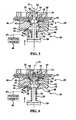
- a portable machine tool generally indicated by the numeral 18 is temporarily attached to a workpiece 16 by means of an electromagnetic clamp generally shown by the numeral 10.
- the machine tool 18 comprises a drill which includes a drill motor 20 that drives a shank 22 for rotation.
- a cutter 24 is mounted on the end of the shank 22 and includes a twist drill 25 portion and a tapered cutter portion 26 for producing a countersink in the workpiece 16 surrounding the hole produced by the drill 25.
- the machine tool 18 and the electromagnetic clamp 10 are mounted on a common, portable tool fixture (not shown).
- the drill motor 20 includes an internal, linear feed mechanism (not shown) which feeds the cutter 24 along a central axis 21 between the retracted position shown in Figure 1 and displaced, cutting positions which will be discussed below.
- a ring shaped disc 30 is loosely sleeved over the shank 22 and is biased into engagement with a shoulder on the cutter by a compression spring 29 passing over the shank 22. As will be discussed later, the disc 30 functions as a closure to control airflows that extract debris produced by the cutter 24.
- the workpiece 16 comprises a pair of metal sheets in which a countersunk hole is to be formed which will receive a fastening rivet (not shown).
- a backing plate 32 of rigid material such as steel is placed on the back side of the workpiece 16 prior to the drilling operation in order to provide workpiece support during the drilling operation.
- the backing plate 32 includes a through hole 34 aligned with the central cutter axis 21 in order to allow the cutter 24 to freely pass through the backing plate 32 at the end of the drill stroke.
- the electromagnetic clamp 10 includes an electromagnet body 12 connected to an electrical power source (not shown), causing the body 12 to act as an electromagnet which clamps itself to the metallic workpiece 16. Where the workpiece 16 is formed of non-metallic plates or pieces, then the steel backing plate 32 completes the magnetic circuit required to produce the necessary clamping force.
- the magnetic clamping force is concentrated through a clamping ring 14 secured to body 12, which surrounds a central passageway 36 extending through the clamp body 12.
- the clamping ring 14 holds the body 12 in spaced relationship to the workpiece 16 so as to form a gap 46 between body 12 and workpiece 16.
- the clamping ring 14 forms a seal between the body 12 and workpiece 16 so that cutting debris from the workpiece 16 cannot escape other than through the passageway 36.
- passageway 36 is a cylindrically shaped through-hole.
- the upper end of passageway 36 functions as a mixing chamber 37 wherein a later discussed supply of fluid is mixed with the cutter debris to improve its flow characteristics.
- the lower end of the passageway 36 includes a section of increased diameter that defines an acceleration chamber 40 having a curved outer curved sidewall 41.
- the end of the passageway 36 opposite the workpiece 16 includes an inlet opening 38 surrounding the shank 22. The inlet opening 38 allows the cutter 24 to pass into the passageway 36 and also permits a relatively large volume of air to enter the passageway 36.
- the body 12 includes fluid supply channels 42 which extend from one side of the body 12, laterally inwardly and communicate with the passageway 36 through inlets 43. In the illustrated example, two, opposing fluid supply channels 42 are provided, however more or less than this number of channels may be provided, depending upon the particular application, geometries, fluid flow rate and other factors.
- the body 12 further includes a debris and fluid exhaust channel 44 which extends from the other side of the body 12 and communicates with the acceleration chamber 40 through an exhaust outlet 45 in the sidewall 41.
- the exhaust channel 44 is connected by a pneumatic line 47 to a source of negative pressure, such as the vacuum source 48 which, as will become later apparent, extracts fluid and debris through the exhaust channel 44.
- the drill motor 20 is turned on and the cutter rpm and feed rate are selected.
- the vacuum source 48 is turned on which draws fluid out of the clamp body 12 through the exhaust channel 44.
- the fluid comprises ambient air surrounding the clamp 10.
- the air being drawn out through the exhaust channel 44 is derived from airflow m 1 which enters the passageway 36 through the inlet opening 38 surrounding the cutter 24. At this point, the air flow m 2 entering the passageway through supply channels 42 is essentially zero.
- Figure 2 shows the cutter 24 having advanced in its feed stroke to contact the workpiece 16.
- the disc 30 moves into engagement with the outer face of the clamp body 12, covering the inlet opening 38 in its entirety.
- the spring 28 holds the disk 30 on the outer face of clamp body 12 while the cutter 24, along with shank 22, continue being displaced toward the workpiece 16.
- airflow m 1 into the passageway 36 goes to zero, and the airflow m 2 through supply channels 42 shifts to a high rate so that the total airflow m tot being exhausted is equal to the supply airflow m 2 .
- FIG 3 shows the twist drill portion 25 of cutter 24 having partially penetrated the workpiece 16, resulting in cutter debris being generated at the interface between the twist drill 25 and workpiece 16.
- the airflow m 2 draws the debris into the mixing chamber 37 where it becomes mixed with the incoming air before passing into the acceleration chamber 40.
- the flow of the air-debris mixture in chamber 40 circulates around the outside area of the chamber 40 in a cyclonic fashion due in part to the curved shape of the sidewall 41 and the fact that the exhaust outlet 45 is positioned in the side wall 41.
- airflow m 1 continues to be zero, the airflow m 2 is at its highest rate, and the total exhaust airflow m tot is equal to airflow m 2 .
- Figure 4 shows the twist drill portion 25 having fully penetrated the workpiece 16, thus completing the hole drilling portion of cutting operation.
- the twist drill 25 penetrates through the workpiece 16
- ambient air within the backing plate opening 24 flows through the flutes/helicoils of the cutter 24, producing an additional source of airflow m 3 into the passageway 36.
- airflow m 1 remains zero while both airflows m 2 and m 3 are at high rates. Consequently the total exhaust flow m tot is the sum of airflows m 2 and m 3 .
- the additional airflow m 3 through the newly formed hole increases the total volume of air through the passageway 36, but decreases the flow velocity.
- the velocity of the air flowing through the passageway 36 must be sufficient to reliably carry the debris to the exhaust channel 44. Accordingly, depending on the particular application and size/geometries of the various features, it may be necessary to partially or even fully close the supply channels 42, which will result in a corresponding increase the velocity of airflow through the passageway 36.
- Figure 5 shows the cutter 24 having advanced further in its stroke, with the tapered section 26 forming a countersink in the hole that has just been drilled.
- airflow m 1 remains zero while both m 2 and m 3 remain high so that the total airflow exhausted from the chamber continues to be the sum of airflows m 2 and m 3 .
- the airflow m 3 carries dust and debris in the flutes and helicoils of the cutter 24 into the passageway 36 where the additional airflow m 2 entering the passageway chamber 36 through inlets 43 is combined with the debris in the mixing chamber 37. Following mixing in the chamber 37, the mixture passes into the acceleration chamber 40 where it is accelerated before being extracted through the exhaust channel 44.
- Figure 6 shows the cutter 24 during the first part of its retraction stroke. Airflow m 2 and m 3 remain high, while airflow m 1 remains zero. As the end of the drill twist 25 begins to clear the workpiece 16, airflow m 3 carries in any remaining debris and dust in the countersink hole into the passageway 36 where it is mixed with additional airflow m 2 and accelerated in chamber 40 before being exhausted through the exhaust channel 44.
- the exact size of the mixing chamber 37, airflow passages 42, 44, 46, etc. will depend on the particular application, size of the machine tool 18, etc. Importantly, however, the velocity of the airflow passing through the mixing chamber 37 must be controlled in order to successfully remove the debris when the maximum amount of debris is being generated, as occurs during the cutting operations shown in Figure 4 , 5 and 6 . For example, during the drilling operation depicted in Figure 3 (when the hole is not yet finished), it can be seen that only airflow m 2 is entering the mixing chamber 37, and the entry channel cross section is optimized for achieving high air velocity.
- a variety of devices and construction features can be devised to control the airflow so that the requisite airflow velocity is maintained in the mixing chamber 37 at the necessary times.
- An example of one such construction is shown in Figure 8 .
- a body 50 which may be part of a workpiece clamp, has a cylindrical central opening defining the mixing chamber 37. Tubes 52, 54 supply airflow m 2 to the mixing chamber 37. The airflow m 2 can be shut off by closing valves 58, 60 controlled by either a solenoid 56 or a mechanical switch 62.
- the airflow m 2 can be supplied to the mixing chamber 37 using a first set of lateral air entry ports 68 formed the wall of body 50, and a second set of air entry ports 70 formed in a rotatable ring 64 that surrounds the body 50.
- a first set of lateral air entry ports 68 formed the wall of body 50 and a second set of air entry ports 70 formed in a rotatable ring 64 that surrounds the body 50.
- maximum airflow is allowed to enter the mixing chamber 37 through these ports.
- the ring 64 is rotated relative to the body 50, the overlapping cross sectional area of the connected ports 68, 70 decreases until the ports 68, 70 are fully closed off, terminating the airflow m 2 .
Landscapes
- Engineering & Computer Science (AREA)
- Mechanical Engineering (AREA)
- Auxiliary Devices For Machine Tools (AREA)
- Drilling And Boring (AREA)
- Processing Of Stones Or Stones Resemblance Materials (AREA)
- Finish Polishing, Edge Sharpening, And Grinding By Specific Grinding Devices (AREA)
Applications Claiming Priority (2)
| Application Number | Priority Date | Filing Date | Title |
|---|---|---|---|
| US11/510,980 US8002503B2 (en) | 2006-08-28 | 2006-08-28 | Debris removal system for cutting tools |
| PCT/US2007/018610 WO2008027266A1 (en) | 2006-08-28 | 2007-08-22 | Debris removal system for cutting tools |
Publications (2)
| Publication Number | Publication Date |
|---|---|
| EP2091687A1 EP2091687A1 (en) | 2009-08-26 |
| EP2091687B1 true EP2091687B1 (en) | 2011-05-25 |
Family
ID=38871600
Family Applications (1)
| Application Number | Title | Priority Date | Filing Date |
|---|---|---|---|
| EP07837237A Not-in-force EP2091687B1 (en) | 2006-08-28 | 2007-08-22 | Debris removal system for cutting tools |
Country Status (6)
| Country | Link |
|---|---|
| US (1) | US8002503B2 (https=) |
| EP (1) | EP2091687B1 (https=) |
| JP (1) | JP5171826B2 (https=) |
| CN (1) | CN101522365B (https=) |
| AT (1) | ATE510655T1 (https=) |
| WO (1) | WO2008027266A1 (https=) |
Families Citing this family (25)
| Publication number | Priority date | Publication date | Assignee | Title |
|---|---|---|---|---|
| US8002503B2 (en) | 2006-08-28 | 2011-08-23 | The Boeing Company | Debris removal system for cutting tools |
| US20080240877A1 (en) * | 2007-03-30 | 2008-10-02 | Ronald Jude Kirby | Cutting device with chip collector |
| JP4795377B2 (ja) * | 2008-03-27 | 2011-10-19 | 日立ビアメカニクス株式会社 | レーザ加工装置 |
| CN101905338A (zh) * | 2009-06-03 | 2010-12-08 | 鸿富锦精密工业(深圳)有限公司 | 除屑器及钻头 |
| US8484795B2 (en) * | 2010-08-11 | 2013-07-16 | Seagate Technology Llc | Collecting debris from a tool |
| FR2975316B1 (fr) * | 2011-05-20 | 2014-05-09 | Airbus Operations Sas | Outil coupant optimise pour un usinage avec aspiration des copeaux |
| ITTO20110492A1 (it) * | 2011-06-07 | 2012-12-08 | Alenia Aeronautica Spa | Ugello e procedimento per l'aspirazione di polveri e trucioli risultanti da operazioni di foratura |
| CN102717124A (zh) * | 2012-06-05 | 2012-10-10 | 江苏天工工具有限公司 | 一种带永磁体的薄板钻 |
| DE102014200198A1 (de) * | 2014-01-09 | 2015-07-09 | Robert Bosch Gmbh | Vorrichtung zur spanabhebenden Bearbeitung eines metallischen Bauteils |
| CN104690598B (zh) * | 2015-02-28 | 2017-02-22 | 蚌埠市金林数控机床制造有限公司 | 一种方便除铁屑的机床 |
| US9682429B2 (en) * | 2015-04-22 | 2017-06-20 | The Boeing Company | Reaction tool and method for forming openings in an aircraft fuselage joint |
| JP6465747B2 (ja) * | 2015-05-21 | 2019-02-06 | ジヤトコ株式会社 | エアブロー装置 |
| DE102015218650B3 (de) * | 2015-06-12 | 2016-10-20 | Schuler Automation Gmbh & Co. Kg | Vorrichtung zum Schneiden von Blechplatinen aus einem Blechband |
| US9884371B2 (en) * | 2015-11-16 | 2018-02-06 | The Boeing Company | Multi-step drilling apparatus and methods utilizing air flow sensing control |
| CN105252316A (zh) * | 2015-11-30 | 2016-01-20 | 苏州众捷汽车零部件有限公司 | 一种带电磁铁的夹具 |
| CN105252315A (zh) * | 2015-11-30 | 2016-01-20 | 苏州众捷汽车零部件有限公司 | 一种夹持工具 |
| US10040155B2 (en) * | 2016-01-19 | 2018-08-07 | The Boeing Company | Air cooled spindle exhaust air redirection system for enhanced machining byproduct recovery |
| US9895750B2 (en) * | 2016-07-19 | 2018-02-20 | The Boeing Company | Fastener and method for fastening to associated structural assembly |
| JP6696948B2 (ja) * | 2017-10-03 | 2020-05-20 | 株式会社スギノマシン | 清掃装置 |
| CN110860941A (zh) * | 2019-11-22 | 2020-03-06 | 深圳市文地科技有限公司 | 一种用于加工零件的具有清洁功能的数控机床 |
| WO2021210076A1 (ja) * | 2020-04-14 | 2021-10-21 | 三菱重工業株式会社 | 穴あけ装置および穴あけ方法 |
| IT202000018625A1 (it) * | 2020-07-30 | 2022-01-30 | Leonardo Spa | Dispositivo ausiliario per la guida di un trapano e per l'aspirazione di polvere e sfridi |
| CN112108695B (zh) * | 2020-08-31 | 2021-08-10 | 珠海视新医用科技有限公司 | 一种内窥镜通道机构制造工艺 |
| CN112705750A (zh) * | 2020-12-16 | 2021-04-27 | 江西昌浩实业有限公司 | 一种铝合金塑钢门窗合页的加工装置 |
| CN117484258B (zh) * | 2023-12-06 | 2026-04-10 | 江苏昶屹电子科技有限公司 | 一种cnc五轴切削铣床 |
Family Cites Families (22)
| Publication number | Priority date | Publication date | Assignee | Title |
|---|---|---|---|---|
| US1857748A (en) * | 1922-06-22 | 1932-05-10 | Clymer Mfg Company | Glass cutting machine |
| US1651353A (en) * | 1924-02-15 | 1927-12-06 | Fyrac Mfg Co | Portable windshield cutter |
| US3351143A (en) * | 1965-06-01 | 1967-11-07 | Alvin V Seibold | Concrete drill bit guide and dust remover |
| US4915550A (en) * | 1988-12-22 | 1990-04-10 | Hitachi Seiko Ltd. | Pressure foot of printed circuit board drilling apparatus |
| US4917547A (en) * | 1989-02-09 | 1990-04-17 | Frederickson Jeffrey W | Apparatus and method for dispensing solution to prevent smear in the manufacture of printed circuit boards |
| JPH03104534A (ja) * | 1989-09-19 | 1991-05-01 | Hitachi Elevator Eng & Service Co Ltd | 電気ドリルの切粉飛散防止工具 |
| DE4037716C1 (https=) * | 1990-11-27 | 1992-04-09 | Hitachi Seiko, Ltd., Ebina, Kanagawa, Jp | |
| GB2262159A (en) * | 1991-12-06 | 1993-06-09 | Kontor Moulding Systems Ltd | Thrust-applying drill hood |
| JPH0755404B2 (ja) * | 1992-12-14 | 1995-06-14 | 富士重工業株式会社 | 穿孔機の冷却集塵装置 |
| US5482411A (en) * | 1994-12-22 | 1996-01-09 | Mcdonnell Douglas Corporation | Method and apparatus for securely clamping a drill motor to a drill plate |
| JPH10337604A (ja) * | 1997-06-05 | 1998-12-22 | Toray Eng Co Ltd | 穴あけ加工装置 |
| US6200075B1 (en) * | 2000-05-16 | 2001-03-13 | The Boeing Company | Drill motor vacuum attachment |
| US6413022B1 (en) * | 2000-09-18 | 2002-07-02 | The Boeing Company | Vacuum clamp device |
| US6902361B2 (en) * | 2001-06-18 | 2005-06-07 | Novator Ab | Fixation device for a portable orbital drilling unit |
| US20030170082A1 (en) * | 2002-03-08 | 2003-09-11 | The Boeing Company | Multiple-port drill plate and method for debris containment |
| US6729811B2 (en) * | 2002-04-01 | 2004-05-04 | K-Line Industries, Inc. | Cutter tool for bore liners |
| US6905291B2 (en) * | 2002-05-30 | 2005-06-14 | The Boeing Company | Apparatus and method for drilling holes and optionally inserting fasteners |
| EP2248619A1 (en) * | 2002-09-16 | 2010-11-10 | Novator AB | An orbital machining apparatus for producing holes and a radial offset mechanism of such an apparatus |
| US7195429B2 (en) * | 2003-10-20 | 2007-03-27 | The Boeing Company | Drill template with integral vacuum attach |
| DE10358030A1 (de) * | 2003-12-11 | 2005-07-07 | Hilti Ag | Zyklonabscheider |
| DE502004001486D1 (de) * | 2004-06-09 | 2006-10-26 | Metabowerke Gmbh | Vorrichtung zum Handhaben eines Bohrwerkzeugs oder Bohrwerkzeuggeräts |
| US8002503B2 (en) | 2006-08-28 | 2011-08-23 | The Boeing Company | Debris removal system for cutting tools |
-
2006
- 2006-08-28 US US11/510,980 patent/US8002503B2/en not_active Expired - Fee Related
-
2007
- 2007-08-22 CN CN2007800364928A patent/CN101522365B/zh not_active Expired - Fee Related
- 2007-08-22 AT AT07837237T patent/ATE510655T1/de not_active IP Right Cessation
- 2007-08-22 WO PCT/US2007/018610 patent/WO2008027266A1/en not_active Ceased
- 2007-08-22 EP EP07837237A patent/EP2091687B1/en not_active Not-in-force
- 2007-08-22 JP JP2009526641A patent/JP5171826B2/ja not_active Expired - Fee Related
Also Published As
| Publication number | Publication date |
|---|---|
| CN101522365A (zh) | 2009-09-02 |
| US20080050193A1 (en) | 2008-02-28 |
| JP5171826B2 (ja) | 2013-03-27 |
| HK1128440A1 (en) | 2009-10-30 |
| JP2010502453A (ja) | 2010-01-28 |
| ATE510655T1 (de) | 2011-06-15 |
| EP2091687A1 (en) | 2009-08-26 |
| WO2008027266A1 (en) | 2008-03-06 |
| US8002503B2 (en) | 2011-08-23 |
| CN101522365B (zh) | 2012-10-24 |
Similar Documents
| Publication | Publication Date | Title |
|---|---|---|
| EP2091687B1 (en) | Debris removal system for cutting tools | |
| US8821213B2 (en) | Piercing and/or cutting devices for abrasive waterjet systems and associated systems and methods | |
| US20030170082A1 (en) | Multiple-port drill plate and method for debris containment | |
| WO2012157468A1 (ja) | ドリル及びそれを用いた穿孔装置 | |
| JP6154202B2 (ja) | 穿孔治具、穿孔ユニット及び穿孔方法 | |
| KR102491059B1 (ko) | 민감성 재료를 절단하기 위한 연마제 유체 제트 절단 시스템, 구성요소 및 관련 방법 | |
| KR100624651B1 (ko) | 다이 및 다이 장치 | |
| EP3466576B1 (en) | Automatic drilling machine for drilling in one-shot at least two holes in a crosspiece structure | |
| KR20130048697A (ko) | 천공 장치의 클램핑 장치 및 에어 구동 드릴 장치 | |
| EP4289535A1 (en) | System and method for drilling a hole for a countersink fastener | |
| HK1128440B (en) | Debris removal system for cutting tools | |
| JPH11170104A (ja) | 穴明け機の工具清掃装置および清掃方法 | |
| CN212217133U (zh) | 一种精加工的钻孔机床 | |
| JP7331250B2 (ja) | 穴あけ装置および穴あけ方法 | |
| KR20170090990A (ko) | 카운터싱크 장치 및 이와 관련된 방법 | |
| EP2835199B1 (en) | Tool holder device | |
| CN221336748U (zh) | 一种直径可调的钻头 | |
| JP2002178207A (ja) | 細穴加工方法とこれに使用する工具ホルダ及びマシニングセンタ | |
| CN222059497U (zh) | 一种便于取出工件的法兰盘夹具 | |
| CN121023110A (zh) | 一种皮革压力机的冲针结构 | |
| KR20110071263A (ko) | 절삭유 공급 조립체 | |
| TWM578332U (zh) | Impeller dust discharge device | |
| JP2004106058A (ja) | ダイ金型及びダイ装置 | |
| KR970069207A (ko) | 다량절삭 성형방법 및 이에 사용되는 cnc 절삭성형기 | |
| JP2001259553A (ja) | エアー・コンプレッサーを使用せず、送風機等を使用する高効率、低騒音、省エネルギー化を可能にする新機構のサンド・ブラスト機器 |
Legal Events
| Date | Code | Title | Description |
|---|---|---|---|
| PUAI | Public reference made under article 153(3) epc to a published international application that has entered the european phase |
Free format text: ORIGINAL CODE: 0009012 |
|
| 17P | Request for examination filed |
Effective date: 20090330 |
|
| AK | Designated contracting states |
Kind code of ref document: A1 Designated state(s): AT BE BG CH CY CZ DE DK EE ES FI FR GB GR HU IE IS IT LI LT LU LV MC MT NL PL PT RO SE SI SK TR |
|
| AX | Request for extension of the european patent |
Extension state: AL BA HR MK RS |
|
| 17Q | First examination report despatched |
Effective date: 20090924 |
|
| REG | Reference to a national code |
Ref country code: HK Ref legal event code: DE Ref document number: 1128440 Country of ref document: HK |
|
| DAX | Request for extension of the european patent (deleted) | ||
| GRAP | Despatch of communication of intention to grant a patent |
Free format text: ORIGINAL CODE: EPIDOSNIGR1 |
|
| GRAS | Grant fee paid |
Free format text: ORIGINAL CODE: EPIDOSNIGR3 |
|
| GRAA | (expected) grant |
Free format text: ORIGINAL CODE: 0009210 |
|
| AK | Designated contracting states |
Kind code of ref document: B1 Designated state(s): AT BE BG CH CY CZ DE DK EE ES FI FR GB GR HU IE IS IT LI LT LU LV MC MT NL PL PT RO SE SI SK TR |
|
| REG | Reference to a national code |
Ref country code: GB Ref legal event code: FG4D |
|
| REG | Reference to a national code |
Ref country code: CH Ref legal event code: EP |
|
| REG | Reference to a national code |
Ref country code: IE Ref legal event code: FG4D |
|
| REG | Reference to a national code |
Ref country code: DE Ref legal event code: R096 Ref document number: 602007014892 Country of ref document: DE Effective date: 20110707 |
|
| REG | Reference to a national code |
Ref country code: NL Ref legal event code: VDEP Effective date: 20110525 |
|
| PG25 | Lapsed in a contracting state [announced via postgrant information from national office to epo] |
Ref country code: PT Free format text: LAPSE BECAUSE OF FAILURE TO SUBMIT A TRANSLATION OF THE DESCRIPTION OR TO PAY THE FEE WITHIN THE PRESCRIBED TIME-LIMIT Effective date: 20110926 Ref country code: SE Free format text: LAPSE BECAUSE OF FAILURE TO SUBMIT A TRANSLATION OF THE DESCRIPTION OR TO PAY THE FEE WITHIN THE PRESCRIBED TIME-LIMIT Effective date: 20110525 Ref country code: LT Free format text: LAPSE BECAUSE OF FAILURE TO SUBMIT A TRANSLATION OF THE DESCRIPTION OR TO PAY THE FEE WITHIN THE PRESCRIBED TIME-LIMIT Effective date: 20110525 |
|
| PG25 | Lapsed in a contracting state [announced via postgrant information from national office to epo] |
Ref country code: SI Free format text: LAPSE BECAUSE OF FAILURE TO SUBMIT A TRANSLATION OF THE DESCRIPTION OR TO PAY THE FEE WITHIN THE PRESCRIBED TIME-LIMIT Effective date: 20110525 Ref country code: BE Free format text: LAPSE BECAUSE OF FAILURE TO SUBMIT A TRANSLATION OF THE DESCRIPTION OR TO PAY THE FEE WITHIN THE PRESCRIBED TIME-LIMIT Effective date: 20110525 Ref country code: CY Free format text: LAPSE BECAUSE OF FAILURE TO SUBMIT A TRANSLATION OF THE DESCRIPTION OR TO PAY THE FEE WITHIN THE PRESCRIBED TIME-LIMIT Effective date: 20110525 Ref country code: LV Free format text: LAPSE BECAUSE OF FAILURE TO SUBMIT A TRANSLATION OF THE DESCRIPTION OR TO PAY THE FEE WITHIN THE PRESCRIBED TIME-LIMIT Effective date: 20110525 Ref country code: FI Free format text: LAPSE BECAUSE OF FAILURE TO SUBMIT A TRANSLATION OF THE DESCRIPTION OR TO PAY THE FEE WITHIN THE PRESCRIBED TIME-LIMIT Effective date: 20110525 Ref country code: IS Free format text: LAPSE BECAUSE OF FAILURE TO SUBMIT A TRANSLATION OF THE DESCRIPTION OR TO PAY THE FEE WITHIN THE PRESCRIBED TIME-LIMIT Effective date: 20110925 Ref country code: AT Free format text: LAPSE BECAUSE OF FAILURE TO SUBMIT A TRANSLATION OF THE DESCRIPTION OR TO PAY THE FEE WITHIN THE PRESCRIBED TIME-LIMIT Effective date: 20110525 Ref country code: GR Free format text: LAPSE BECAUSE OF FAILURE TO SUBMIT A TRANSLATION OF THE DESCRIPTION OR TO PAY THE FEE WITHIN THE PRESCRIBED TIME-LIMIT Effective date: 20110826 Ref country code: ES Free format text: LAPSE BECAUSE OF FAILURE TO SUBMIT A TRANSLATION OF THE DESCRIPTION OR TO PAY THE FEE WITHIN THE PRESCRIBED TIME-LIMIT Effective date: 20110905 |
|
| REG | Reference to a national code |
Ref country code: HK Ref legal event code: GR Ref document number: 1128440 Country of ref document: HK |
|
| PG25 | Lapsed in a contracting state [announced via postgrant information from national office to epo] |
Ref country code: MT Free format text: LAPSE BECAUSE OF FAILURE TO SUBMIT A TRANSLATION OF THE DESCRIPTION OR TO PAY THE FEE WITHIN THE PRESCRIBED TIME-LIMIT Effective date: 20110525 Ref country code: NL Free format text: LAPSE BECAUSE OF FAILURE TO SUBMIT A TRANSLATION OF THE DESCRIPTION OR TO PAY THE FEE WITHIN THE PRESCRIBED TIME-LIMIT Effective date: 20110525 |
|
| PG25 | Lapsed in a contracting state [announced via postgrant information from national office to epo] |
Ref country code: EE Free format text: LAPSE BECAUSE OF FAILURE TO SUBMIT A TRANSLATION OF THE DESCRIPTION OR TO PAY THE FEE WITHIN THE PRESCRIBED TIME-LIMIT Effective date: 20110525 Ref country code: CZ Free format text: LAPSE BECAUSE OF FAILURE TO SUBMIT A TRANSLATION OF THE DESCRIPTION OR TO PAY THE FEE WITHIN THE PRESCRIBED TIME-LIMIT Effective date: 20110525 |
|
| PG25 | Lapsed in a contracting state [announced via postgrant information from national office to epo] |
Ref country code: PL Free format text: LAPSE BECAUSE OF FAILURE TO SUBMIT A TRANSLATION OF THE DESCRIPTION OR TO PAY THE FEE WITHIN THE PRESCRIBED TIME-LIMIT Effective date: 20110525 Ref country code: RO Free format text: LAPSE BECAUSE OF FAILURE TO SUBMIT A TRANSLATION OF THE DESCRIPTION OR TO PAY THE FEE WITHIN THE PRESCRIBED TIME-LIMIT Effective date: 20110525 Ref country code: DK Free format text: LAPSE BECAUSE OF FAILURE TO SUBMIT A TRANSLATION OF THE DESCRIPTION OR TO PAY THE FEE WITHIN THE PRESCRIBED TIME-LIMIT Effective date: 20110525 Ref country code: SK Free format text: LAPSE BECAUSE OF FAILURE TO SUBMIT A TRANSLATION OF THE DESCRIPTION OR TO PAY THE FEE WITHIN THE PRESCRIBED TIME-LIMIT Effective date: 20110525 |
|
| PG25 | Lapsed in a contracting state [announced via postgrant information from national office to epo] |
Ref country code: MC Free format text: LAPSE BECAUSE OF NON-PAYMENT OF DUE FEES Effective date: 20110831 |
|
| PLBE | No opposition filed within time limit |
Free format text: ORIGINAL CODE: 0009261 |
|
| REG | Reference to a national code |
Ref country code: CH Ref legal event code: PL |
|
| STAA | Information on the status of an ep patent application or granted ep patent |
Free format text: STATUS: NO OPPOSITION FILED WITHIN TIME LIMIT |
|
| PG25 | Lapsed in a contracting state [announced via postgrant information from national office to epo] |
Ref country code: CH Free format text: LAPSE BECAUSE OF NON-PAYMENT OF DUE FEES Effective date: 20110831 Ref country code: LI Free format text: LAPSE BECAUSE OF NON-PAYMENT OF DUE FEES Effective date: 20110831 |
|
| 26N | No opposition filed |
Effective date: 20120228 |
|
| REG | Reference to a national code |
Ref country code: IE Ref legal event code: MM4A |
|
| PG25 | Lapsed in a contracting state [announced via postgrant information from national office to epo] |
Ref country code: IT Free format text: LAPSE BECAUSE OF FAILURE TO SUBMIT A TRANSLATION OF THE DESCRIPTION OR TO PAY THE FEE WITHIN THE PRESCRIBED TIME-LIMIT Effective date: 20110525 |
|
| REG | Reference to a national code |
Ref country code: DE Ref legal event code: R097 Ref document number: 602007014892 Country of ref document: DE Effective date: 20120228 |
|
| PG25 | Lapsed in a contracting state [announced via postgrant information from national office to epo] |
Ref country code: IE Free format text: LAPSE BECAUSE OF NON-PAYMENT OF DUE FEES Effective date: 20110822 |
|
| PG25 | Lapsed in a contracting state [announced via postgrant information from national office to epo] |
Ref country code: LU Free format text: LAPSE BECAUSE OF NON-PAYMENT OF DUE FEES Effective date: 20110822 |
|
| PG25 | Lapsed in a contracting state [announced via postgrant information from national office to epo] |
Ref country code: BG Free format text: LAPSE BECAUSE OF FAILURE TO SUBMIT A TRANSLATION OF THE DESCRIPTION OR TO PAY THE FEE WITHIN THE PRESCRIBED TIME-LIMIT Effective date: 20110825 |
|
| PG25 | Lapsed in a contracting state [announced via postgrant information from national office to epo] |
Ref country code: TR Free format text: LAPSE BECAUSE OF FAILURE TO SUBMIT A TRANSLATION OF THE DESCRIPTION OR TO PAY THE FEE WITHIN THE PRESCRIBED TIME-LIMIT Effective date: 20110525 |
|
| PG25 | Lapsed in a contracting state [announced via postgrant information from national office to epo] |
Ref country code: HU Free format text: LAPSE BECAUSE OF FAILURE TO SUBMIT A TRANSLATION OF THE DESCRIPTION OR TO PAY THE FEE WITHIN THE PRESCRIBED TIME-LIMIT Effective date: 20110525 |
|
| REG | Reference to a national code |
Ref country code: FR Ref legal event code: PLFP Year of fee payment: 10 |
|
| REG | Reference to a national code |
Ref country code: FR Ref legal event code: PLFP Year of fee payment: 11 |
|
| REG | Reference to a national code |
Ref country code: FR Ref legal event code: PLFP Year of fee payment: 12 |
|
| PGFP | Annual fee paid to national office [announced via postgrant information from national office to epo] |
Ref country code: GB Payment date: 20220829 Year of fee payment: 16 Ref country code: DE Payment date: 20220829 Year of fee payment: 16 |
|
| PGFP | Annual fee paid to national office [announced via postgrant information from national office to epo] |
Ref country code: FR Payment date: 20220825 Year of fee payment: 16 |
|
| REG | Reference to a national code |
Ref country code: DE Ref legal event code: R119 Ref document number: 602007014892 Country of ref document: DE |
|
| GBPC | Gb: european patent ceased through non-payment of renewal fee |
Effective date: 20230822 |
|
| PG25 | Lapsed in a contracting state [announced via postgrant information from national office to epo] |
Ref country code: GB Free format text: LAPSE BECAUSE OF NON-PAYMENT OF DUE FEES Effective date: 20230822 |
|
| PG25 | Lapsed in a contracting state [announced via postgrant information from national office to epo] |
Ref country code: GB Free format text: LAPSE BECAUSE OF NON-PAYMENT OF DUE FEES Effective date: 20230822 Ref country code: FR Free format text: LAPSE BECAUSE OF NON-PAYMENT OF DUE FEES Effective date: 20230831 Ref country code: DE Free format text: LAPSE BECAUSE OF NON-PAYMENT OF DUE FEES Effective date: 20240301 |