EP2090736A1 - Rollladen - Google Patents
Rollladen Download PDFInfo
- Publication number
- EP2090736A1 EP2090736A1 EP08169455A EP08169455A EP2090736A1 EP 2090736 A1 EP2090736 A1 EP 2090736A1 EP 08169455 A EP08169455 A EP 08169455A EP 08169455 A EP08169455 A EP 08169455A EP 2090736 A1 EP2090736 A1 EP 2090736A1
- Authority
- EP
- European Patent Office
- Prior art keywords
- coupling piece
- roller shutter
- winding shaft
- groove
- shutter according
- Prior art date
- Legal status (The legal status is an assumption and is not a legal conclusion. Google has not performed a legal analysis and makes no representation as to the accuracy of the status listed.)
- Granted
Links
- 230000008878 coupling Effects 0.000 claims abstract description 50
- 238000010168 coupling process Methods 0.000 claims abstract description 50
- 238000005859 coupling reaction Methods 0.000 claims abstract description 50
- 238000004804 winding Methods 0.000 claims description 31
- 230000000717 retained effect Effects 0.000 abstract 1
- 241000446313 Lamella Species 0.000 description 3
- 229910000831 Steel Inorganic materials 0.000 description 2
- 239000010959 steel Substances 0.000 description 2
- XAGFODPZIPBFFR-UHFFFAOYSA-N aluminium Chemical compound [Al] XAGFODPZIPBFFR-UHFFFAOYSA-N 0.000 description 1
- 229910052782 aluminium Inorganic materials 0.000 description 1
- 238000003780 insertion Methods 0.000 description 1
- 230000037431 insertion Effects 0.000 description 1
- 238000009434 installation Methods 0.000 description 1
- 238000012805 post-processing Methods 0.000 description 1
- 230000037072 sun protection Effects 0.000 description 1
- 230000007704 transition Effects 0.000 description 1
- 230000000007 visual effect Effects 0.000 description 1
Images


Classifications
-
- E—FIXED CONSTRUCTIONS
- E06—DOORS, WINDOWS, SHUTTERS, OR ROLLER BLINDS IN GENERAL; LADDERS
- E06B—FIXED OR MOVABLE CLOSURES FOR OPENINGS IN BUILDINGS, VEHICLES, FENCES OR LIKE ENCLOSURES IN GENERAL, e.g. DOORS, WINDOWS, BLINDS, GATES
- E06B9/00—Screening or protective devices for wall or similar openings, with or without operating or securing mechanisms; Closures of similar construction
- E06B9/02—Shutters, movable grilles, or other safety closing devices, e.g. against burglary
- E06B9/08—Roll-type closures
- E06B9/11—Roller shutters
- E06B9/17—Parts or details of roller shutters, e.g. suspension devices, shutter boxes, wicket doors, ventilation openings
- E06B9/171—Rollers therefor; Fastening roller shutters to rollers
- E06B9/172—Rollers therefor; Fastening roller shutters to rollers by clamping bars
Definitions
- the present invention relates to a roller shutter, with a rotatable winding shaft, on which a plurality of fins are wound.
- At least one coupling piece is fixed to the winding shaft on a groove on which the slats are held.
- the coupling piece is embraced on opposite sides by the groove U-shaped, so that accidental release is avoided.
- the groove on one side may have a groove wall which extends higher in the radial direction of the winding shaft than on the opposite side of the groove.
- the coupling piece can be clamped by a screw.
- the screw can be supported with an end portion against a wall on the winding shaft.
- a webbing is fixed to the coupling piece, which may be designed to hold the slats as a band, rope or chain.
- the webbing is guided through a slot on the coupling piece.
- a plurality of spaced-apart coupling pieces are preferably mounted on the winding shaft.
- the winding shaft is preferably made of an extruded extruded profile on which a groove for pivoting one or more coupling pieces is formed. This eliminates post-processing steps.
- the length of the webbing is adjustable.
- an adjustment screw may be provided for adjusting the length of the webbing on the coupling piece.
- a roller shutter 1 comprises a plurality of fins 2, which together form a Lamellenbehang 3.
- the roller shutter 1 or the Lamellenbehang 3 is usually a building opening, such as windows, doors or gates completely or partially closed.
- the roller shutter 1 is mainly a visual and sun protection, but can also act burglar-resistant and heat-insulating.
- the slats 2 are guided laterally in rails 4 and can be wound in an upper and / or lower roller shutter housing 5.
- a rotatably mounted winding shaft 6 is located in the roller shutter housing 5.
- a groove 7 is formed on which a plurality of spaced-apart coupling pieces 8 are mounted.
- a webbing 9 is attached, which serves for the connection of the individual slats 2 to a Lamellenbehang 3.
- the coupling pieces 8 can be adjusted in the axial direction of the winding shaft 6. Further, the length of the straps 9 can be adjusted to the coupling piece 8 to change the Behanginate.
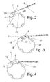
- FIG. 2 is a side view of the winding shaft 6 shown during assembly.
- the winding shaft 6 is made as extruded extruded profile, preferably made of aluminum, and comprises a groove 7, on which a coupling piece 8 can be fixed.
- the groove 7 comprises on a first side a receptacle 10, which is bounded by a directed into the groove 7 in the projection 20.
- a strip-shaped projection 21 of the coupling piece 8 substantially form-fitting inserted.
- a receptacle 11 is formed, into which a portion of the coupling piece 8 can be inserted.
- the receptacle 11 is bounded by a web 19 in the circumferential direction, on which a radially inwardly directed groove 12 is formed.
- FIG. 2 First, the coupling piece 8 is pivoted with one end into the receptacle 11 in the radial direction. Subsequently, the coupling piece 8 is pivoted so that it engages with a projection 21 in the receptacle 20. Then the in FIG. 3 reached shown position.
- the wedge-shaped projection 21 is first inserted into the receptacle 10, and an overlying end portion 22 of the coupling piece 8 is inserted into the groove 12 which is formed on the web 19.
- the coupling piece 8 is thereby held self-locking on the groove 7.
- the coupling piece 8 is fixed by means of a screw 13, preferably a pointed grub screw, wherein the screw 13 is pressed against a bottom of the groove 7, so that the coupling piece 8 is clamped to the groove 7 and the groove 12.
- one side of the groove 7 is formed higher than the opposite side, so that after insertion of the coupling piece 8 when winding the slats 2, first, a circular Aufwickelkontur arises.
- This has the advantage that no transition edge is formed at the beginning of the slat curtain when the slats 2 are wound on the winding shaft 6. This avoids unwanted buckling of the slats. 2
- the coupling piece 8 comprises a slot 15 through which the webbing 9, in this case a steel cable, is performed.
- the steel cable or the webbing 9 are thereby secured and clamped on the slot 15 via a screw 14 arranged perpendicular thereto.
- a screw 13 is provided on the coupling piece 8, which can fix and secure the coupling piece 8 to the groove 7.
- the coupling piece 8 can be flexibly adjusted to the winding shaft 6. First, there is an adjustment in the longitudinal direction of the groove 7, as indicated by the arrow 16. By fixing the screw 13, the coupling piece is then secured. In order to adjust the length of the webbing 9, the screw 14 is first loosened, and then fixed the webbing 9 in the desired position again.
- a contact surface 18 is further formed, which serves to bear a first lamella 2 or so-called lamella holders. These lamellae holder can be arranged on the webbing 9 in order to facilitate the hanging and fixing of the webbing 9 and thus the lamellae. If no lamella holders or similar stoppers are arranged on the belt 9, can the Behangin be determined by the contact surface 18 to adjust the position of the webbing 9 according to, as shown by the arrow 17.
- the coupling piece 8 can be positioned on the groove 7 by pivoting and then fixed. Different mechanical means for fixing the coupling piece 8 to the winding shaft 6 can be provided.
- 3 spaced-apart coupling pieces 8 are mounted on the winding shaft 6, wherein depending on the width of the shutter 1 and more or fewer coupling pieces 8 are fixed to the winding shaft 6.
Landscapes
- Engineering & Computer Science (AREA)
- Structural Engineering (AREA)
- Architecture (AREA)
- Civil Engineering (AREA)
- Operating, Guiding And Securing Of Roll- Type Closing Members (AREA)
Abstract
Description
- Die vorliegende Erfindung betrifft einen Rollladen, mit einer drehbaren Wickelwelle, auf die eine Vielzahl von Lamellen aufwickelbar sind.
- Bei bekannten Rollläden werden meist die Gurtbänder, an denen die einzelnen Lamellen befestigt sind, an einer Wickelwelle verschraubt. Dadurch kann der aus Lamellen gebildete Behang durch Drehen der Wickelwelle auf- und abgewickelt werden. Bei einem solchen Rollladen ist nachteilig, dass die Montage und Justierung der Lamellen aufwendig ist.
- Es ist daher Aufgabe der vorliegenden Erfindung, einen Rollladen zu schaffen, der leicht zu montieren ist und eine einfache Verstellung ermöglicht. Diese Aufgabe wird mit einem Rollladen mit den Merkmalen des Anspruches 1 gelöst.
- Erfindungsgemäß ist an der Wickelwelle an einer Nut mindestens ein Kopplungsstück festgelegt, an dem die Lamellen gehalten sind. Dadurch kann über das Kopplungsstück auf einfache Weise eine Montage des Lamellenbehanges erfolgen, wobei bei der Fixierung des Kopplungsstückes nur eine geringe Anzahl an Arbeitsschritten notwendig ist.
- Gemäß einer bevorzugten Ausgestaltung der Erfindung ist das Kopplungsstück an gegenüberliegenden Seiten durch die Nut U-förmig umgriffen, so dass ein versehentliches Lösen vermieden wird. Dabei kann die Nut an einer Seite eine Nutwand besitzen, die sich in radiale Richtung der Wickelwelle höher erstreckt als an der gegenüberliegenden Seite der Nut. Dadurch kann die erste Wicklung auf der Wickelwelle so erfolgen, dass die Lamellen ohne Stufe auf der Wickelwelle aufgewickelt werden können, bis die erste Lage an Lamellen erreicht wird. Auf der Wickelwelle bilden sich dadurch geringere Stufen beim Aufwickeln der Lamellen in radiale Richtung aus.
- Für eine einfache Montage kann das Kopplungsstück über eine Schraube klemmend fixierbar sein. Die Schraube kann dabei mit einem Endabschnitt gegen eine Wand an der Wickelwelle abgestützt sein.
- Vorzugsweise ist an dem Kopplungsstück ein Gurtband festgelegt, das zur Halterung der Lamellen als Band, Seil oder Kette ausgebildet sein kann. Gemäß einer bevorzugten Ausgestaltung ist das Gurtband dabei durch einen Schlitz an dem Kopplungsstück geführt.
- Für eine stabile Befestigung der Lamellen an dem Rollladen sind an der Wickelwelle vorzugsweise mehrere voneinander beabstandete Kopplungsstücke montiert.
- Die Wickelwelle ist vorzugsweise aus einem extrudierten Strangpressprofil hergestellt, an dem eine Nut zum Einschwenken ein oder mehrerer Kopplungsstücke ausgebildet ist. Dadurch entfallen Nachbearbeitungsschritte.
- Um die Lage der Lamellen einstellen zu können, ist vorzugsweise die Länge des Gurtbandes verstellbar ausgebildet. Dabei kann zum Verstellen der Länge des Gurtbandes an dem Kopplungsstück eine Justierschraube vorgesehen sein.
- Die Erfindung wird nachfolgend anhand eines Ausführungsbeispieles mit Bezug auf die beigefügten Zeichnungen näher erläutert. Es zeigen:
- Figur 1
- eine perspektivische Ansicht eines Ausführungsbeispieles eines erfindungsgemäßem Rollladens;
- Figuren 2 bis 4
- mehrere Seitenansichten des Rollladens der
Figur 1 im Bereich der Wickelwelle bei der Montage, und - Figuren 5 und 6
- zwei perspektivische Ansichten eines Kopplungsstückes der
Figur 1 . - Ein Rollladen 1 umfasst eine Vielzahl von Lamellen 2, die zusammen einen Lamellenbehang 3 bilden. Mit dem Rollladen 1 bzw. dem Lamellenbehang 3 wird meist eine Gebäudeöffnung, wie Fenster, Türen oder Tore ganz oder teilweise verschlossen. Der Rollladen 1 ist dabei hauptsächlich ein Sicht- und Sonnenschutz, kann aber auch einbruchshemmend und wärmedämmend wirken. Die Lamellen 2 sind seitlich in Schienen 4 geführt und können in einem oberen und/oder unteren Rollladengehäuse 5 aufgewickelt werden. Hierfür befindet sich in dem Rollladengehäuse 5 eine drehbar gelagerte Wickelwelle 6.
- An der Wickelwelle 6 ist eine Nut 7 ausgebildet, an der mehrere voneinander beabstandete Kopplungsstücke 8 montiert sind. An jedem Kopplungsstück 8 ist ein Gurtband 9 befestigt, das zur Verbindung der einzelnen Lamellen 2 zu einem Lamellenbehang 3 dient. Die Kopplungsstücke 8 können dabei in Achsrichtung der Wickelwelle 6 verstellt werden. Ferner kann die Länge der Gurtbänder 9 an dem Kopplungsstück 8 justiert werden, um die Behanglänge zu verändern.
- In
Figur 2 ist eine Seitenansicht der Wickelwelle 6 bei der Montage dargestellt. Die Wickelwelle 6 ist als extrudiertes Strangpressprofil, vorzugsweise aus Aluminium, hergestellt und umfasst eine Nut 7, an der ein Kopplungsstück 8 festlegbar ist. Die Nut 7 umfasst an einer ersten Seite eine Aufnahme 10, die durch einen nach innen in die Nut 7 gerichteten Vorsprung 20 begrenzt ist. In die Aufnahme 20 ist ein leistenförmiger Vorsprung 21 des Kopplungsstückes 8 im Wesentlichen formschlüssig einfügbar. - An der gegenüberliegenden Seite ist eine Aufnahme 11 ausgebildet, in die ein Abschnitt des Kopplungsstückes 8 einfügbar ist. Die Aufnahme 11 ist dabei durch einen Steg 19 in Umfangsrichtung begrenzt, an dem eine radial nach innen gerichtete Nut 12 ausgebildet ist. In
Figur 2 wird zunächst das Kopplungsstück 8 mit einem Ende in die Aufnahme 11 in radialer Richtung eingeschwenkt. Anschließend wird das Kopplungsstück 8 so verschwenkt, dass es mit einem Vorsprung 21 in die Aufnahme 20 eingreift. Dann wird die inFigur 3 gezeigte Position erreicht. - Um das Kopplungsstück 8 anschließend zu fixieren, wird zunächst der keilförmige Vorsprung 21 in die Aufnahme 10 eingefügt, und ein überliegender Endabschnitt 22 des Kopplungsstückes 8 wird in die Nut 12 eingefügt, die an dem, Steg 19 ausgebildet ist. Das Kopplungsstück 8 ist dadurch selbstsichernd an der Nut 7 gehalten. Zusätzlich wird mittels einer Schraube 13, vorzugsweise einer spitzen Madenschraube das Kopplungsstück 8 fixiert, wobei die Schraube 13 gegen einen Boden der Nut 7 gedrückt wird, so dass das Kopplungsstück 8 an der Nut 7 und der Nut 12 festgeklemmt wird. Dabei ist eine Seite der Nut 7 höher ausgebildet als die gegenüberliegende Seite, so dass nach dem Einsetzen des Kopplungsstückes 8 beim Aufwickeln der Lamellen 2 zunächst eine kreisförmige Aufwickelkontur entsteht. Dies hat den Vorteil, dass keine Übergangskante am Anfang des Lamellenbehanges entsteht, wenn die Lamellen 2 auf der Wickelwelle 6 aufgewickelt werden. Dies vermeidet ein ungewolltes Knicken der Lamellen 2.
- In den
Figuren 5 und 6 ist das Kopplungsstück 8 im Detail dargestellt. Das Kopplungsstück 8 umfasst einen Schlitz 15, durch den das Gurtband 9, in diesem Fall ein Stahlseil, durchgeführt ist. Das Stahlseil bzw. das Gurtband 9 werden dabei an dem Schlitz 15 über eine senkrecht dazu angeordnete Schraube 14 gesichert und eingeklemmt. Dadurch kann die Länge des Gurtbandes 9 justiert werden, in dem die Schraube 14 leicht geöffnet und das Gurtband 9 in der gewünschten Position fixiert wird. Ferner ist an dem Kopplungsstück 8 eine Schraube 13 vorgesehen, die das Kopplungsstück 8 an der Nut 7 fixieren und sichern kann. - Das Kopplungsstück 8 lässt sich flexibel an der Wickelwelle 6 einstellen. Zunächst besteht eine Verstellmöglichkeit in Längsrichtung der Nut 7, wie dies mit dem Pfeil 16 angedeutet ist. Durch Fixieren der Schraube 13 wird das Kopplungsstück dann gesichert. Um die Länge des Gurtbandes 9 einstellen zu können, wird die Schraube 14 zunächst gelockert, und dann das Gurtband 9 in der gewünschten Position wieder fixiert.
- An dem Kopplungsstück 8 ist ferner eine Anlagefläche 18 ausgebildet, die zur Anlage einer ersten Lamelle 2 oder von sogenannten Lamellenhaltern dient. Diese Lamellenhalter können an dem Gurtband 9 angeordnet sein, um das Einhängen und Fixieren des Gurtbandes 9 und damit des Lamellenbehanges zu erleichtern. Sind keine Lamellenhalter oder ähnliche Stopper an dem Gurtband 9 angeordnet, kann die Behanglänge durch die Anlagefläche 18 vorbestimmt werden, um die Lage des Gurtbandes 9 entsprechend einzustellen, wie dies mit dem Pfeil 17 dargestellt ist.
- In dem dargestellten Ausführungsbeispiel kann das Kopplungsstück 8 an der Nut 7 durch Einschwenken positioniert und anschließend festgelegt werden. Es können unterschiedliche mechanische Mittel zum Festlegen des Kopplungsstückes 8 an der Wickelwelle 6 vorgesehen sein. In dem dargestellten Ausführungsbeispiel sind 3 voneinander beabstandete Kopplungsstücke 8 an der Wickelwelle 6 montiert, wobei je nach Breite des Rollladens 1 auch mehr oder weniger Kopplungsstücke 8 an der Wickelwelle 6 festgelegt werden.
Claims (11)
- Rollladen (1), mit einer drehbaren Wickelwelle (6), auf die eine Vielzahl von Lamellen (2) aufwickelbar sind, dadurch gekennzeichnet, dass an der Wickelwelle (6) an einer Nut (7) mindestens ein Kopplungsstück (8) festgelegt ist, an dem die Lamellen (2) gehalten sind.
- Rollladen nach Anspruch 1, dadurch gekennzeichnet, dass das Kopplungsstück (8) in die Nut (7) an der Wickelwelle (6) in radiale Richtung einschwenkbar ist.
- Rollladen nach Anspruch 1 oder 2, dadurch gekennzeichnet, dass das Kopplungsstück (8) an gegenüberliegenden Seiten durch die Nut (7) U-förmig umgriffen ist.
- Rollladen nach einem der Ansprüche 1 bis 3, dadurch gekennzeichnet, dass die Nut (7) an einer Seite eine Nutwand (19) besitzt, die sich in radiale Richtung der Wickelwelle (6) höher erstreckt als an der gegenüberliegenden Seite (20) der Nut (7).
- Rollladen nach einem der Ansprüche 1 bis 4, dadurch gekennzeichnet, dass das Kopplungsstück (8) über eine Schraube (13) klemmend fixierbar ist.
- Rollladen nach einem der Ansprüche 1 bis 5, dadurch gekennzeichnet, dass an dem Kopplungsstück (8) ein Gurtband (9) festgelegt ist.
- Rollladen nach Anspruch 6, dadurch gekennzeichnet, dass das Gurtband (9) durch einen Schlitz (15) an dem Kopplungsstück (8) geführt ist.
- Rollladen nach einem der Ansprüche 1 bis 7, dadurch gekennzeichnet, dass an der Wickelwelle (6) mehrere voneinander beabstandete Kopplungsstücke (8) montiert sind.
- Rollladen nach einem der Ansprüche 1 bis 8, dadurch gekennzeichnet, dass die Wickelwelle (6) aus einem extrudierten Strangpressprofil hergestellt ist.
- Rollladen nach einem der Ansprüche 1 bis 9, dadurch gekennzeichnet, dass die Länge des Gurtbandes (9) verstellbar ausgebildet ist.
- Rollladen nach Anspruch 10, dadurch gekennzeichnet, dass zum Verstellen der Länge des Gurtbandes (9) an dem Kopplungsstück (8) eine Justierschraube (14) vorgesehen ist.
Applications Claiming Priority (1)
| Application Number | Priority Date | Filing Date | Title |
|---|---|---|---|
| DE200820002073 DE202008002073U1 (de) | 2008-02-15 | 2008-02-15 | Rollladen |
Publications (2)
| Publication Number | Publication Date |
|---|---|
| EP2090736A1 true EP2090736A1 (de) | 2009-08-19 |
| EP2090736B1 EP2090736B1 (de) | 2016-01-27 |
Family
ID=40343585
Family Applications (1)
| Application Number | Title | Priority Date | Filing Date |
|---|---|---|---|
| EP08169455.6A Not-in-force EP2090736B1 (de) | 2008-02-15 | 2008-11-19 | Rollladen |
Country Status (3)
| Country | Link |
|---|---|
| EP (1) | EP2090736B1 (de) |
| DE (1) | DE202008002073U1 (de) |
| ES (1) | ES2566733T3 (de) |
Cited By (1)
| Publication number | Priority date | Publication date | Assignee | Title |
|---|---|---|---|---|
| US11865910B2 (en) | 2019-03-18 | 2024-01-09 | Hbpo Gmbh | Device for controlling and guiding a closure element |
Citations (4)
| Publication number | Priority date | Publication date | Assignee | Title |
|---|---|---|---|---|
| FR2547617A1 (fr) | 1983-06-16 | 1984-12-21 | Griesser Sa | Attache pour fixer les sangles d'attache d'un tablier sur l'axe d'enroulement d'un volet roulant ou d'une construction similaire |
| FR2816299A3 (fr) * | 2000-11-08 | 2002-05-10 | Somfy | Tube d'enroulement pour produit enroulable tel que toile ou volet roulant |
| EP1233141A1 (de) | 2001-02-20 | 2002-08-21 | Deprat Jean S.A. | Sicherheitsvorrichtung gegen das Hochschieben von Rolladenpanzer |
| EP1336717A2 (de) * | 2002-02-14 | 2003-08-20 | Hörmann Kg Dissen | Rolltor |
Family Cites Families (3)
| Publication number | Priority date | Publication date | Assignee | Title |
|---|---|---|---|---|
| DE7017599U (de) * | 1970-05-12 | 1971-01-28 | Aeberli Kurt | Rolladenwelle. |
| AT397979B (de) * | 1991-11-15 | 1994-08-25 | Kraler Franz | Rolladen |
| US5275223A (en) * | 1992-02-28 | 1994-01-04 | Sebastian Magro | Support roller provided with roll-up mechanism for rolling doors, gates and the like |
-
2008
- 2008-02-15 DE DE200820002073 patent/DE202008002073U1/de not_active Expired - Lifetime
- 2008-11-19 ES ES08169455.6T patent/ES2566733T3/es active Active
- 2008-11-19 EP EP08169455.6A patent/EP2090736B1/de not_active Not-in-force
Patent Citations (4)
| Publication number | Priority date | Publication date | Assignee | Title |
|---|---|---|---|---|
| FR2547617A1 (fr) | 1983-06-16 | 1984-12-21 | Griesser Sa | Attache pour fixer les sangles d'attache d'un tablier sur l'axe d'enroulement d'un volet roulant ou d'une construction similaire |
| FR2816299A3 (fr) * | 2000-11-08 | 2002-05-10 | Somfy | Tube d'enroulement pour produit enroulable tel que toile ou volet roulant |
| EP1233141A1 (de) | 2001-02-20 | 2002-08-21 | Deprat Jean S.A. | Sicherheitsvorrichtung gegen das Hochschieben von Rolladenpanzer |
| EP1336717A2 (de) * | 2002-02-14 | 2003-08-20 | Hörmann Kg Dissen | Rolltor |
Cited By (1)
| Publication number | Priority date | Publication date | Assignee | Title |
|---|---|---|---|---|
| US11865910B2 (en) | 2019-03-18 | 2024-01-09 | Hbpo Gmbh | Device for controlling and guiding a closure element |
Also Published As
| Publication number | Publication date |
|---|---|
| EP2090736B1 (de) | 2016-01-27 |
| DE202008002073U1 (de) | 2009-07-02 |
| ES2566733T3 (es) | 2016-04-15 |
Similar Documents
| Publication | Publication Date | Title |
|---|---|---|
| DE69519764T2 (de) | Jalousierbarer Rolladen | |
| EP0519241B1 (de) | Zugvorrichtung vorzugsweise zum Ein- und Ausziehen eines Tuches für eine Store, sowie dazugehörige Store | |
| EP1923533A2 (de) | Rolltor | |
| EP2631414A2 (de) | Führungsschiene für Senkrechtmarkise und Senkrechtmarkise | |
| DE4006212C2 (de) | Jalousie | |
| DE3037759A1 (de) | Rafflamellenstore | |
| DE202011051989U1 (de) | Pflanzenkastenhalterung zur Befestigung eines Pflanzenkastens an Handläufen und Brüstungen | |
| DE4036892A1 (de) | Spannvorrichtung fuer ein flexibles, flaechiges abdeckmittel | |
| DE4034614C2 (de) | ||
| EP2199527B1 (de) | Rollraumverkleidungsbausatz sowie Rollladenbausatz | |
| EP2090736B1 (de) | Rollladen | |
| WO2019038030A1 (de) | Fingerschutzvorrichtung | |
| DE70451C (de) | Rollvorhang mit in der Breiten-Richtung gekrümmten Querscbienen | |
| DE19844146C2 (de) | Sonnenschutzeinrichtung | |
| DE2733461A1 (de) | Verriegelung fuer rolladen und rolltore | |
| DE10031275C1 (de) | Flexibles Aufhängeband für Rolladenpanzer | |
| DE69715451T2 (de) | Rolladen | |
| DE102014003498B4 (de) | Verfahren zum Einbau einer Wickelwelle einer Gebäudeöffnungsverschattungsvorrichtung | |
| DE1683177A1 (de) | Kordelantriebsvorrichtung fuer Jalousien mit Lamellen | |
| AT7883U1 (de) | Rollo | |
| DE10236869A1 (de) | Raffstore mit Wendelager | |
| LU102269B1 (de) | Raffstore und Verfahren zum Modifizieren eines Raffstores | |
| EP1267031A1 (de) | Sicherungseinrichtung für Rolläden oder dergleichen | |
| DE4015995A1 (de) | Solarbeschattung | |
| LU102268B1 (de) | Raffstore und Verfahren zum Modifizieren eines Raffstores |
Legal Events
| Date | Code | Title | Description |
|---|---|---|---|
| PUAI | Public reference made under article 153(3) epc to a published international application that has entered the european phase |
Free format text: ORIGINAL CODE: 0009012 |
|
| AK | Designated contracting states |
Kind code of ref document: A1 Designated state(s): AT BE BG CH CY CZ DE DK EE ES FI FR GB GR HR HU IE IS IT LI LT LU LV MC MT NL NO PL PT RO SE SI SK TR |
|
| AX | Request for extension of the european patent |
Extension state: AL BA MK RS |
|
| 17P | Request for examination filed |
Effective date: 20091208 |
|
| 17Q | First examination report despatched |
Effective date: 20100203 |
|
| AKX | Designation fees paid |
Designated state(s): AT BE BG CH CY CZ DE DK EE ES FI FR GB GR HR HU IE IS IT LI LT LU LV MC MT NL NO PL PT RO SE SI SK TR |
|
| REG | Reference to a national code |
Ref country code: DE Ref legal event code: R079 Ref document number: 502008013776 Country of ref document: DE Free format text: PREVIOUS MAIN CLASS: E06B0009171000 Ipc: E06B0009172000 |
|
| RIC1 | Information provided on ipc code assigned before grant |
Ipc: E06B 9/172 20060101AFI20150803BHEP |
|
| GRAP | Despatch of communication of intention to grant a patent |
Free format text: ORIGINAL CODE: EPIDOSNIGR1 |
|
| INTG | Intention to grant announced |
Effective date: 20150921 |
|
| GRAS | Grant fee paid |
Free format text: ORIGINAL CODE: EPIDOSNIGR3 |
|
| GRAA | (expected) grant |
Free format text: ORIGINAL CODE: 0009210 |
|
| AK | Designated contracting states |
Kind code of ref document: B1 Designated state(s): AT BE BG CH CY CZ DE DK EE ES FI FR GB GR HR HU IE IS IT LI LT LU LV MC MT NL NO PL PT RO SE SI SK TR |
|
| REG | Reference to a national code |
Ref country code: GB Ref legal event code: FG4D Free format text: NOT ENGLISH |
|
| REG | Reference to a national code |
Ref country code: CH Ref legal event code: EP |
|
| REG | Reference to a national code |
Ref country code: AT Ref legal event code: REF Ref document number: 772813 Country of ref document: AT Kind code of ref document: T Effective date: 20160215 |
|
| REG | Reference to a national code |
Ref country code: IE Ref legal event code: FG4D Free format text: LANGUAGE OF EP DOCUMENT: GERMAN |
|
| REG | Reference to a national code |
Ref country code: CH Ref legal event code: NV Representative=s name: ISLER AND PEDRAZZINI AG, CH |
|
| REG | Reference to a national code |
Ref country code: DE Ref legal event code: R096 Ref document number: 502008013776 Country of ref document: DE |
|
| REG | Reference to a national code |
Ref country code: ES Ref legal event code: FG2A Ref document number: 2566733 Country of ref document: ES Kind code of ref document: T3 Effective date: 20160415 |
|
| REG | Reference to a national code |
Ref country code: LT Ref legal event code: MG4D |
|
| REG | Reference to a national code |
Ref country code: NL Ref legal event code: MP Effective date: 20160127 |
|
| PG25 | Lapsed in a contracting state [announced via postgrant information from national office to epo] |
Ref country code: NL Free format text: LAPSE BECAUSE OF FAILURE TO SUBMIT A TRANSLATION OF THE DESCRIPTION OR TO PAY THE FEE WITHIN THE PRESCRIBED TIME-LIMIT Effective date: 20160127 |
|
| PG25 | Lapsed in a contracting state [announced via postgrant information from national office to epo] |
Ref country code: FI Free format text: LAPSE BECAUSE OF FAILURE TO SUBMIT A TRANSLATION OF THE DESCRIPTION OR TO PAY THE FEE WITHIN THE PRESCRIBED TIME-LIMIT Effective date: 20160127 Ref country code: GR Free format text: LAPSE BECAUSE OF FAILURE TO SUBMIT A TRANSLATION OF THE DESCRIPTION OR TO PAY THE FEE WITHIN THE PRESCRIBED TIME-LIMIT Effective date: 20160428 Ref country code: HR Free format text: LAPSE BECAUSE OF FAILURE TO SUBMIT A TRANSLATION OF THE DESCRIPTION OR TO PAY THE FEE WITHIN THE PRESCRIBED TIME-LIMIT Effective date: 20160127 Ref country code: NO Free format text: LAPSE BECAUSE OF FAILURE TO SUBMIT A TRANSLATION OF THE DESCRIPTION OR TO PAY THE FEE WITHIN THE PRESCRIBED TIME-LIMIT Effective date: 20160427 |
|
| PG25 | Lapsed in a contracting state [announced via postgrant information from national office to epo] |
Ref country code: IS Free format text: LAPSE BECAUSE OF FAILURE TO SUBMIT A TRANSLATION OF THE DESCRIPTION OR TO PAY THE FEE WITHIN THE PRESCRIBED TIME-LIMIT Effective date: 20160527 Ref country code: LV Free format text: LAPSE BECAUSE OF FAILURE TO SUBMIT A TRANSLATION OF THE DESCRIPTION OR TO PAY THE FEE WITHIN THE PRESCRIBED TIME-LIMIT Effective date: 20160127 Ref country code: PL Free format text: LAPSE BECAUSE OF FAILURE TO SUBMIT A TRANSLATION OF THE DESCRIPTION OR TO PAY THE FEE WITHIN THE PRESCRIBED TIME-LIMIT Effective date: 20160127 Ref country code: PT Free format text: LAPSE BECAUSE OF FAILURE TO SUBMIT A TRANSLATION OF THE DESCRIPTION OR TO PAY THE FEE WITHIN THE PRESCRIBED TIME-LIMIT Effective date: 20160527 Ref country code: SE Free format text: LAPSE BECAUSE OF FAILURE TO SUBMIT A TRANSLATION OF THE DESCRIPTION OR TO PAY THE FEE WITHIN THE PRESCRIBED TIME-LIMIT Effective date: 20160127 Ref country code: LT Free format text: LAPSE BECAUSE OF FAILURE TO SUBMIT A TRANSLATION OF THE DESCRIPTION OR TO PAY THE FEE WITHIN THE PRESCRIBED TIME-LIMIT Effective date: 20160127 |
|
| REG | Reference to a national code |
Ref country code: DE Ref legal event code: R097 Ref document number: 502008013776 Country of ref document: DE |
|
| PG25 | Lapsed in a contracting state [announced via postgrant information from national office to epo] |
Ref country code: EE Free format text: LAPSE BECAUSE OF FAILURE TO SUBMIT A TRANSLATION OF THE DESCRIPTION OR TO PAY THE FEE WITHIN THE PRESCRIBED TIME-LIMIT Effective date: 20160127 Ref country code: DK Free format text: LAPSE BECAUSE OF FAILURE TO SUBMIT A TRANSLATION OF THE DESCRIPTION OR TO PAY THE FEE WITHIN THE PRESCRIBED TIME-LIMIT Effective date: 20160127 |
|
| PG25 | Lapsed in a contracting state [announced via postgrant information from national office to epo] |
Ref country code: CZ Free format text: LAPSE BECAUSE OF FAILURE TO SUBMIT A TRANSLATION OF THE DESCRIPTION OR TO PAY THE FEE WITHIN THE PRESCRIBED TIME-LIMIT Effective date: 20160127 Ref country code: RO Free format text: LAPSE BECAUSE OF FAILURE TO SUBMIT A TRANSLATION OF THE DESCRIPTION OR TO PAY THE FEE WITHIN THE PRESCRIBED TIME-LIMIT Effective date: 20160127 Ref country code: SK Free format text: LAPSE BECAUSE OF FAILURE TO SUBMIT A TRANSLATION OF THE DESCRIPTION OR TO PAY THE FEE WITHIN THE PRESCRIBED TIME-LIMIT Effective date: 20160127 |
|
| PLBE | No opposition filed within time limit |
Free format text: ORIGINAL CODE: 0009261 |
|
| STAA | Information on the status of an ep patent application or granted ep patent |
Free format text: STATUS: NO OPPOSITION FILED WITHIN TIME LIMIT |
|
| 26N | No opposition filed |
Effective date: 20161028 |
|
| PG25 | Lapsed in a contracting state [announced via postgrant information from national office to epo] |
Ref country code: BG Free format text: LAPSE BECAUSE OF FAILURE TO SUBMIT A TRANSLATION OF THE DESCRIPTION OR TO PAY THE FEE WITHIN THE PRESCRIBED TIME-LIMIT Effective date: 20160427 Ref country code: SI Free format text: LAPSE BECAUSE OF FAILURE TO SUBMIT A TRANSLATION OF THE DESCRIPTION OR TO PAY THE FEE WITHIN THE PRESCRIBED TIME-LIMIT Effective date: 20160127 |
|
| GBPC | Gb: european patent ceased through non-payment of renewal fee |
Effective date: 20161119 |
|
| REG | Reference to a national code |
Ref country code: IE Ref legal event code: MM4A |
|
| REG | Reference to a national code |
Ref country code: FR Ref legal event code: ST Effective date: 20170731 |
|
| PG25 | Lapsed in a contracting state [announced via postgrant information from national office to epo] |
Ref country code: LU Free format text: LAPSE BECAUSE OF NON-PAYMENT OF DUE FEES Effective date: 20161130 |
|
| PG25 | Lapsed in a contracting state [announced via postgrant information from national office to epo] |
Ref country code: FR Free format text: LAPSE BECAUSE OF NON-PAYMENT OF DUE FEES Effective date: 20161130 |
|
| PG25 | Lapsed in a contracting state [announced via postgrant information from national office to epo] |
Ref country code: GB Free format text: LAPSE BECAUSE OF NON-PAYMENT OF DUE FEES Effective date: 20161119 Ref country code: IE Free format text: LAPSE BECAUSE OF NON-PAYMENT OF DUE FEES Effective date: 20161119 |
|
| PGFP | Annual fee paid to national office [announced via postgrant information from national office to epo] |
Ref country code: ES Payment date: 20171201 Year of fee payment: 10 Ref country code: BE Payment date: 20171122 Year of fee payment: 10 |
|
| PG25 | Lapsed in a contracting state [announced via postgrant information from national office to epo] |
Ref country code: CY Free format text: LAPSE BECAUSE OF FAILURE TO SUBMIT A TRANSLATION OF THE DESCRIPTION OR TO PAY THE FEE WITHIN THE PRESCRIBED TIME-LIMIT Effective date: 20160127 Ref country code: HU Free format text: LAPSE BECAUSE OF FAILURE TO SUBMIT A TRANSLATION OF THE DESCRIPTION OR TO PAY THE FEE WITHIN THE PRESCRIBED TIME-LIMIT; INVALID AB INITIO Effective date: 20081119 |
|
| PG25 | Lapsed in a contracting state [announced via postgrant information from national office to epo] |
Ref country code: MC Free format text: LAPSE BECAUSE OF FAILURE TO SUBMIT A TRANSLATION OF THE DESCRIPTION OR TO PAY THE FEE WITHIN THE PRESCRIBED TIME-LIMIT Effective date: 20160127 Ref country code: TR Free format text: LAPSE BECAUSE OF FAILURE TO SUBMIT A TRANSLATION OF THE DESCRIPTION OR TO PAY THE FEE WITHIN THE PRESCRIBED TIME-LIMIT Effective date: 20160127 |
|
| PG25 | Lapsed in a contracting state [announced via postgrant information from national office to epo] |
Ref country code: MT Free format text: LAPSE BECAUSE OF FAILURE TO SUBMIT A TRANSLATION OF THE DESCRIPTION OR TO PAY THE FEE WITHIN THE PRESCRIBED TIME-LIMIT Effective date: 20160127 |
|
| REG | Reference to a national code |
Ref country code: BE Ref legal event code: MM Effective date: 20181130 |
|
| PG25 | Lapsed in a contracting state [announced via postgrant information from national office to epo] |
Ref country code: BE Free format text: LAPSE BECAUSE OF NON-PAYMENT OF DUE FEES Effective date: 20181130 |
|
| REG | Reference to a national code |
Ref country code: ES Ref legal event code: FD2A Effective date: 20200103 |
|
| PG25 | Lapsed in a contracting state [announced via postgrant information from national office to epo] |
Ref country code: ES Free format text: LAPSE BECAUSE OF NON-PAYMENT OF DUE FEES Effective date: 20181120 |
|
| PGFP | Annual fee paid to national office [announced via postgrant information from national office to epo] |
Ref country code: CH Payment date: 20191113 Year of fee payment: 12 Ref country code: AT Payment date: 20191114 Year of fee payment: 12 |
|
| PGFP | Annual fee paid to national office [announced via postgrant information from national office to epo] |
Ref country code: IT Payment date: 20201130 Year of fee payment: 13 |
|
| PGFP | Annual fee paid to national office [announced via postgrant information from national office to epo] |
Ref country code: DE Payment date: 20201218 Year of fee payment: 13 |
|
| REG | Reference to a national code |
Ref country code: CH Ref legal event code: PL |
|
| REG | Reference to a national code |
Ref country code: AT Ref legal event code: MM01 Ref document number: 772813 Country of ref document: AT Kind code of ref document: T Effective date: 20201119 |
|
| PG25 | Lapsed in a contracting state [announced via postgrant information from national office to epo] |
Ref country code: CH Free format text: LAPSE BECAUSE OF NON-PAYMENT OF DUE FEES Effective date: 20201130 Ref country code: AT Free format text: LAPSE BECAUSE OF NON-PAYMENT OF DUE FEES Effective date: 20201119 Ref country code: LI Free format text: LAPSE BECAUSE OF NON-PAYMENT OF DUE FEES Effective date: 20201130 |
|
| REG | Reference to a national code |
Ref country code: DE Ref legal event code: R119 Ref document number: 502008013776 Country of ref document: DE |
|
| PG25 | Lapsed in a contracting state [announced via postgrant information from national office to epo] |
Ref country code: DE Free format text: LAPSE BECAUSE OF NON-PAYMENT OF DUE FEES Effective date: 20220601 |
|
| PG25 | Lapsed in a contracting state [announced via postgrant information from national office to epo] |
Ref country code: IT Free format text: LAPSE BECAUSE OF NON-PAYMENT OF DUE FEES Effective date: 20211119 |