EP2089531B1 - Biosensorsystem mit verbesserter stabilität und hämatokrit-ausführung - Google Patents
Biosensorsystem mit verbesserter stabilität und hämatokrit-ausführung Download PDFInfo
- Publication number
- EP2089531B1 EP2089531B1 EP07814768.3A EP07814768A EP2089531B1 EP 2089531 B1 EP2089531 B1 EP 2089531B1 EP 07814768 A EP07814768 A EP 07814768A EP 2089531 B1 EP2089531 B1 EP 2089531B1
- Authority
- EP
- European Patent Office
- Prior art keywords
- mediator
- reagent
- sample
- sensor strip
- seconds
- Prior art date
- Legal status (The legal status is an assumption and is not a legal conclusion. Google has not performed a legal analysis and makes no representation as to the accuracy of the status listed.)
- Active
Links
- 238000005534 hematocrit Methods 0.000 title description 72
- 239000003153 chemical reaction reagent Substances 0.000 claims description 145
- 102000004190 Enzymes Human genes 0.000 claims description 95
- 108090000790 Enzymes Proteins 0.000 claims description 95
- 239000012491 analyte Substances 0.000 claims description 66
- 239000000203 mixture Substances 0.000 claims description 64
- 230000005284 excitation Effects 0.000 claims description 61
- 230000008021 deposition Effects 0.000 claims description 58
- 238000005259 measurement Methods 0.000 claims description 47
- 239000004020 conductor Substances 0.000 claims description 46
- 229920002134 Carboxymethyl cellulose Polymers 0.000 claims description 26
- 238000001208 nuclear magnetic resonance pulse sequence Methods 0.000 claims description 26
- 239000001768 carboxy methyl cellulose Substances 0.000 claims description 24
- 235000010948 carboxy methyl cellulose Nutrition 0.000 claims description 24
- 239000008112 carboxymethyl-cellulose Substances 0.000 claims description 24
- 229940105329 carboxymethylcellulose Drugs 0.000 claims description 24
- 238000000034 method Methods 0.000 claims description 24
- 239000000463 material Substances 0.000 claims description 23
- 239000011230 binding agent Substances 0.000 claims description 19
- 230000027756 respiratory electron transport chain Effects 0.000 claims description 11
- YAGKRVSRTSUGEY-UHFFFAOYSA-N ferricyanide Chemical compound [Fe+3].N#[C-].N#[C-].N#[C-].N#[C-].N#[C-].N#[C-] YAGKRVSRTSUGEY-UHFFFAOYSA-N 0.000 claims description 8
- -1 poly(ethylene oxide) Polymers 0.000 claims description 8
- XLYOFNOQVPJJNP-UHFFFAOYSA-N water Substances O XLYOFNOQVPJJNP-UHFFFAOYSA-N 0.000 claims description 7
- 229920003171 Poly (ethylene oxide) Polymers 0.000 claims description 5
- 239000004372 Polyvinyl alcohol Substances 0.000 claims description 5
- 238000006703 hydration reaction Methods 0.000 claims description 5
- 229920002451 polyvinyl alcohol Polymers 0.000 claims description 5
- 229920002678 cellulose Polymers 0.000 claims description 3
- 239000001913 cellulose Substances 0.000 claims description 3
- 230000036571 hydration Effects 0.000 claims description 3
- DLZPPUIHGWXDNJ-UHFFFAOYSA-N n-phenylphenothiazin-3-imine Chemical class C1=CC=CC=C1N=C1C=C2SC3=CC=CC=C3N=C2C=C1 DLZPPUIHGWXDNJ-UHFFFAOYSA-N 0.000 claims description 3
- LJXXBBCNKKOAHS-UHFFFAOYSA-N n-phenylphenoxazin-3-imine Chemical class C1=CC=CC=C1N=C1C=C2OC3=CC=CC=C3N=C2C=C1 LJXXBBCNKKOAHS-UHFFFAOYSA-N 0.000 claims description 3
- 150000003839 salts Chemical class 0.000 claims description 3
- 239000002253 acid Substances 0.000 claims description 2
- 150000007513 acids Chemical class 0.000 claims description 2
- 229940088598 enzyme Drugs 0.000 description 95
- 239000000523 sample Substances 0.000 description 77
- 238000000151 deposition Methods 0.000 description 65
- WQZGKKKJIJFFOK-GASJEMHNSA-N Glucose Natural products OC[C@H]1OC(O)[C@H](O)[C@@H](O)[C@@H]1O WQZGKKKJIJFFOK-GASJEMHNSA-N 0.000 description 58
- 239000008103 glucose Substances 0.000 description 58
- 241000894007 species Species 0.000 description 38
- 230000000694 effects Effects 0.000 description 37
- 238000007254 oxidation reaction Methods 0.000 description 31
- 230000003647 oxidation Effects 0.000 description 29
- 239000000243 solution Substances 0.000 description 29
- 238000004458 analytical method Methods 0.000 description 28
- 210000004369 blood Anatomy 0.000 description 25
- 239000008280 blood Substances 0.000 description 25
- 238000006722 reduction reaction Methods 0.000 description 22
- 230000009467 reduction Effects 0.000 description 21
- 229920000642 polymer Polymers 0.000 description 19
- 230000002829 reductive effect Effects 0.000 description 19
- 238000003860 storage Methods 0.000 description 19
- 230000007774 longterm Effects 0.000 description 17
- 239000000872 buffer Substances 0.000 description 13
- 210000003743 erythrocyte Anatomy 0.000 description 13
- 229910052799 carbon Inorganic materials 0.000 description 11
- MMXZSJMASHPLLR-UHFFFAOYSA-N pyrroloquinoline quinone Chemical compound C12=C(C(O)=O)C=C(C(O)=O)N=C2C(=O)C(=O)C2=C1NC(C(=O)O)=C2 MMXZSJMASHPLLR-UHFFFAOYSA-N 0.000 description 11
- 239000008363 phosphate buffer Substances 0.000 description 10
- 238000006479 redox reaction Methods 0.000 description 10
- 230000035945 sensitivity Effects 0.000 description 10
- 239000000126 substance Substances 0.000 description 10
- OKTJSMMVPCPJKN-UHFFFAOYSA-N Carbon Chemical compound [C] OKTJSMMVPCPJKN-UHFFFAOYSA-N 0.000 description 9
- 239000013060 biological fluid Substances 0.000 description 9
- 238000006243 chemical reaction Methods 0.000 description 9
- 229910052751 metal Inorganic materials 0.000 description 9
- 239000002184 metal Substances 0.000 description 9
- 108090000854 Oxidoreductases Proteins 0.000 description 8
- 102000004316 Oxidoreductases Human genes 0.000 description 8
- 230000007423 decrease Effects 0.000 description 8
- 238000009792 diffusion process Methods 0.000 description 8
- 238000012546 transfer Methods 0.000 description 8
- 108010050375 Glucose 1-Dehydrogenase Proteins 0.000 description 7
- 235000019420 glucose oxidase Nutrition 0.000 description 7
- 239000007788 liquid Substances 0.000 description 7
- 108010015776 Glucose oxidase Proteins 0.000 description 6
- 239000004366 Glucose oxidase Substances 0.000 description 6
- KDLHZDBZIXYQEI-UHFFFAOYSA-N Palladium Chemical compound [Pd] KDLHZDBZIXYQEI-UHFFFAOYSA-N 0.000 description 6
- 238000003556 assay Methods 0.000 description 6
- 238000000840 electrochemical analysis Methods 0.000 description 6
- 229940116332 glucose oxidase Drugs 0.000 description 6
- BASFCYQUMIYNBI-UHFFFAOYSA-N platinum Chemical compound [Pt] BASFCYQUMIYNBI-UHFFFAOYSA-N 0.000 description 6
- 230000004044 response Effects 0.000 description 6
- 229910052723 transition metal Inorganic materials 0.000 description 6
- 231100000673 dose–response relationship Toxicity 0.000 description 5
- XEEYBQQBJWHFJM-UHFFFAOYSA-N iron Substances [Fe] XEEYBQQBJWHFJM-UHFFFAOYSA-N 0.000 description 5
- 238000004519 manufacturing process Methods 0.000 description 5
- 150000002990 phenothiazines Chemical class 0.000 description 5
- QVGXLLKOCUKJST-UHFFFAOYSA-N atomic oxygen Chemical compound [O] QVGXLLKOCUKJST-UHFFFAOYSA-N 0.000 description 4
- 230000008859 change Effects 0.000 description 4
- 108010029645 galactitol 2-dehydrogenase Proteins 0.000 description 4
- 230000001965 increasing effect Effects 0.000 description 4
- 239000003446 ligand Substances 0.000 description 4
- 238000011068 loading method Methods 0.000 description 4
- 230000001590 oxidative effect Effects 0.000 description 4
- 229910052760 oxygen Inorganic materials 0.000 description 4
- 239000001301 oxygen Substances 0.000 description 4
- 238000007639 printing Methods 0.000 description 4
- 238000012360 testing method Methods 0.000 description 4
- 150000003624 transition metals Chemical class 0.000 description 4
- MYMOFIZGZYHOMD-UHFFFAOYSA-N Dioxygen Chemical compound O=O MYMOFIZGZYHOMD-UHFFFAOYSA-N 0.000 description 3
- YXFVVABEGXRONW-UHFFFAOYSA-N Toluene Chemical compound CC1=CC=CC=C1 YXFVVABEGXRONW-UHFFFAOYSA-N 0.000 description 3
- XJLXINKUBYWONI-DQQFMEOOSA-N [[(2r,3r,4r,5r)-5-(6-aminopurin-9-yl)-3-hydroxy-4-phosphonooxyoxolan-2-yl]methoxy-hydroxyphosphoryl] [(2s,3r,4s,5s)-5-(3-carbamoylpyridin-1-ium-1-yl)-3,4-dihydroxyoxolan-2-yl]methyl phosphate Chemical compound NC(=O)C1=CC=C[N+]([C@@H]2[C@H]([C@@H](O)[C@H](COP([O-])(=O)OP(O)(=O)OC[C@@H]3[C@H]([C@@H](OP(O)(O)=O)[C@@H](O3)N3C4=NC=NC(N)=C4N=C3)O)O2)O)=C1 XJLXINKUBYWONI-DQQFMEOOSA-N 0.000 description 3
- 239000012472 biological sample Substances 0.000 description 3
- 125000004432 carbon atom Chemical group C* 0.000 description 3
- 150000004696 coordination complex Chemical class 0.000 description 3
- 206010012601 diabetes mellitus Diseases 0.000 description 3
- 238000010586 diagram Methods 0.000 description 3
- 229910001882 dioxygen Inorganic materials 0.000 description 3
- 238000009472 formulation Methods 0.000 description 3
- PCHJSUWPFVWCPO-UHFFFAOYSA-N gold Chemical compound [Au] PCHJSUWPFVWCPO-UHFFFAOYSA-N 0.000 description 3
- 229910052737 gold Inorganic materials 0.000 description 3
- 239000010931 gold Substances 0.000 description 3
- 239000004615 ingredient Substances 0.000 description 3
- 229930027945 nicotinamide-adenine dinucleotide Natural products 0.000 description 3
- 229910052763 palladium Inorganic materials 0.000 description 3
- 229910052697 platinum Inorganic materials 0.000 description 3
- 230000002441 reversible effect Effects 0.000 description 3
- 239000011550 stock solution Substances 0.000 description 3
- AZQWKYJCGOJGHM-UHFFFAOYSA-N 1,4-benzoquinone Chemical compound O=C1C=CC(=O)C=C1 AZQWKYJCGOJGHM-UHFFFAOYSA-N 0.000 description 2
- IJGRMHOSHXDMSA-UHFFFAOYSA-N Atomic nitrogen Chemical compound N#N IJGRMHOSHXDMSA-UHFFFAOYSA-N 0.000 description 2
- BPYKTIZUTYGOLE-IFADSCNNSA-N Bilirubin Chemical compound N1C(=O)C(C)=C(C=C)\C1=C\C1=C(C)C(CCC(O)=O)=C(CC2=C(C(C)=C(\C=C/3C(=C(C=C)C(=O)N\3)C)N2)CCC(O)=O)N1 BPYKTIZUTYGOLE-IFADSCNNSA-N 0.000 description 2
- 241000218691 Cupressaceae Species 0.000 description 2
- 101710088194 Dehydrogenase Proteins 0.000 description 2
- LFQSCWFLJHTTHZ-UHFFFAOYSA-N Ethanol Chemical compound CCO LFQSCWFLJHTTHZ-UHFFFAOYSA-N 0.000 description 2
- IMROMDMJAWUWLK-UHFFFAOYSA-N Ethenol Chemical group OC=C IMROMDMJAWUWLK-UHFFFAOYSA-N 0.000 description 2
- 239000001856 Ethyl cellulose Substances 0.000 description 2
- 229920002153 Hydroxypropyl cellulose Polymers 0.000 description 2
- BAWFJGJZGIEFAR-NNYOXOHSSA-N NAD zwitterion Chemical compound NC(=O)C1=CC=C[N+]([C@H]2[C@@H]([C@H](O)[C@@H](COP([O-])(=O)OP(O)(=O)OC[C@@H]3[C@H]([C@@H](O)[C@@H](O3)N3C4=NC=NC(N)=C4N=C3)O)O2)O)=C1 BAWFJGJZGIEFAR-NNYOXOHSSA-N 0.000 description 2
- VYPSYNLAJGMNEJ-UHFFFAOYSA-N Silicium dioxide Chemical compound O=[Si]=O VYPSYNLAJGMNEJ-UHFFFAOYSA-N 0.000 description 2
- 230000032683 aging Effects 0.000 description 2
- 125000004429 atom Chemical group 0.000 description 2
- 230000009286 beneficial effect Effects 0.000 description 2
- 150000001721 carbon Chemical group 0.000 description 2
- 230000015556 catabolic process Effects 0.000 description 2
- 239000003795 chemical substances by application Substances 0.000 description 2
- HVYWMOMLDIMFJA-DPAQBDIFSA-N cholesterol Chemical compound C1C=C2C[C@@H](O)CC[C@]2(C)[C@@H]2[C@@H]1[C@@H]1CC[C@H]([C@H](C)CCCC(C)C)[C@@]1(C)CC2 HVYWMOMLDIMFJA-DPAQBDIFSA-N 0.000 description 2
- 239000011248 coating agent Substances 0.000 description 2
- 238000000576 coating method Methods 0.000 description 2
- 238000007796 conventional method Methods 0.000 description 2
- 230000000875 corresponding effect Effects 0.000 description 2
- 125000004093 cyano group Chemical group *C#N 0.000 description 2
- 230000003247 decreasing effect Effects 0.000 description 2
- 238000006731 degradation reaction Methods 0.000 description 2
- 238000013461 design Methods 0.000 description 2
- 239000012992 electron transfer agent Substances 0.000 description 2
- 230000006353 environmental stress Effects 0.000 description 2
- 229920001249 ethyl cellulose Polymers 0.000 description 2
- 235000019325 ethyl cellulose Nutrition 0.000 description 2
- VWWQXMAJTJZDQX-UYBVJOGSSA-N flavin adenine dinucleotide Chemical compound C1=NC2=C(N)N=CN=C2N1[C@@H]([C@H](O)[C@@H]1O)O[C@@H]1CO[P@](O)(=O)O[P@@](O)(=O)OC[C@@H](O)[C@@H](O)[C@@H](O)CN1C2=NC(=O)NC(=O)C2=NC2=C1C=C(C)C(C)=C2 VWWQXMAJTJZDQX-UYBVJOGSSA-N 0.000 description 2
- 235000019162 flavin adenine dinucleotide Nutrition 0.000 description 2
- 239000011714 flavin adenine dinucleotide Substances 0.000 description 2
- 229940093632 flavin-adenine dinucleotide Drugs 0.000 description 2
- 239000011888 foil Substances 0.000 description 2
- 239000001863 hydroxypropyl cellulose Substances 0.000 description 2
- 235000010977 hydroxypropyl cellulose Nutrition 0.000 description 2
- 230000003993 interaction Effects 0.000 description 2
- 230000002452 interceptive effect Effects 0.000 description 2
- 229910052742 iron Inorganic materials 0.000 description 2
- YTOVAWUSMUMHIM-UHFFFAOYSA-N iron(2+);5-methylcyclopenta-1,3-diene Chemical compound [Fe+2].C[C-]1C=CC=C1.C[C-]1C=CC=C1 YTOVAWUSMUMHIM-UHFFFAOYSA-N 0.000 description 2
- 238000000691 measurement method Methods 0.000 description 2
- 150000002739 metals Chemical class 0.000 description 2
- 229950006238 nadide Drugs 0.000 description 2
- 229920000036 polyvinylpyrrolidone Polymers 0.000 description 2
- 239000001267 polyvinylpyrrolidone Substances 0.000 description 2
- 235000013855 polyvinylpyrrolidone Nutrition 0.000 description 2
- 239000011148 porous material Substances 0.000 description 2
- 230000008569 process Effects 0.000 description 2
- 229910052707 ruthenium Inorganic materials 0.000 description 2
- 210000003296 saliva Anatomy 0.000 description 2
- 239000002002 slurry Substances 0.000 description 2
- 239000007787 solid Substances 0.000 description 2
- 239000000758 substrate Substances 0.000 description 2
- 210000002700 urine Anatomy 0.000 description 2
- LNAZSHAWQACDHT-XIYTZBAFSA-N (2r,3r,4s,5r,6s)-4,5-dimethoxy-2-(methoxymethyl)-3-[(2s,3r,4s,5r,6r)-3,4,5-trimethoxy-6-(methoxymethyl)oxan-2-yl]oxy-6-[(2r,3r,4s,5r,6r)-4,5,6-trimethoxy-2-(methoxymethyl)oxan-3-yl]oxyoxane Chemical compound CO[C@@H]1[C@@H](OC)[C@H](OC)[C@@H](COC)O[C@H]1O[C@H]1[C@H](OC)[C@@H](OC)[C@H](O[C@H]2[C@@H]([C@@H](OC)[C@H](OC)O[C@@H]2COC)OC)O[C@@H]1COC LNAZSHAWQACDHT-XIYTZBAFSA-N 0.000 description 1
- 150000005208 1,4-dihydroxybenzenes Chemical class 0.000 description 1
- WJFKNYWRSNBZNX-UHFFFAOYSA-N 10H-phenothiazine Chemical compound C1=CC=C2NC3=CC=CC=C3SC2=C1 WJFKNYWRSNBZNX-UHFFFAOYSA-N 0.000 description 1
- SMZOUWXMTYCWNB-UHFFFAOYSA-N 2-(2-methoxy-5-methylphenyl)ethanamine Chemical compound COC1=CC=C(C)C=C1CCN SMZOUWXMTYCWNB-UHFFFAOYSA-N 0.000 description 1
- NIXOWILDQLNWCW-UHFFFAOYSA-N 2-Propenoic acid Natural products OC(=O)C=C NIXOWILDQLNWCW-UHFFFAOYSA-N 0.000 description 1
- WHBMMWSBFZVSSR-UHFFFAOYSA-N 3-hydroxybutyric acid Chemical compound CC(O)CC(O)=O WHBMMWSBFZVSSR-UHFFFAOYSA-N 0.000 description 1
- BKIKFYRTTUYTJZ-UHFFFAOYSA-N 7-hydroxy-9,9-dimethylacridin-2-one Chemical compound C1=C(O)C=C2C(C)(C)C3=CC(=O)C=CC3=NC2=C1 BKIKFYRTTUYTJZ-UHFFFAOYSA-N 0.000 description 1
- 108010021809 Alcohol dehydrogenase Proteins 0.000 description 1
- 102000007698 Alcohol dehydrogenase Human genes 0.000 description 1
- 102100039702 Alcohol dehydrogenase class-3 Human genes 0.000 description 1
- 108010025188 Alcohol oxidase Proteins 0.000 description 1
- 108010006591 Apoenzymes Proteins 0.000 description 1
- WSNMPAVSZJSIMT-UHFFFAOYSA-N COc1c(C)c2COC(=O)c2c(O)c1CC(O)C1(C)CCC(=O)O1 Chemical compound COc1c(C)c2COC(=O)c2c(O)c1CC(O)C1(C)CCC(=O)O1 WSNMPAVSZJSIMT-UHFFFAOYSA-N 0.000 description 1
- RYGMFSIKBFXOCR-UHFFFAOYSA-N Copper Chemical compound [Cu] RYGMFSIKBFXOCR-UHFFFAOYSA-N 0.000 description 1
- 108020005199 Dehydrogenases Proteins 0.000 description 1
- 229920002307 Dextran Polymers 0.000 description 1
- 229920000896 Ethulose Polymers 0.000 description 1
- ZZSNKZQZMQGXPY-UHFFFAOYSA-N Ethyl cellulose Chemical compound CCOCC1OC(OC)C(OCC)C(OCC)C1OC1C(O)C(O)C(OC)C(CO)O1 ZZSNKZQZMQGXPY-UHFFFAOYSA-N 0.000 description 1
- 239000001859 Ethyl hydroxyethyl cellulose Substances 0.000 description 1
- 108010010803 Gelatin Proteins 0.000 description 1
- 102000002794 Glucosephosphate Dehydrogenase Human genes 0.000 description 1
- 108010018962 Glucosephosphate Dehydrogenase Proteins 0.000 description 1
- 102000003855 L-lactate dehydrogenase Human genes 0.000 description 1
- 108700023483 L-lactate dehydrogenases Proteins 0.000 description 1
- JVTAAEKCZFNVCJ-UHFFFAOYSA-M Lactate Chemical compound CC(O)C([O-])=O JVTAAEKCZFNVCJ-UHFFFAOYSA-M 0.000 description 1
- 108010026217 Malate Dehydrogenase Proteins 0.000 description 1
- 102000013460 Malate Dehydrogenase Human genes 0.000 description 1
- CERQOIWHTDAKMF-UHFFFAOYSA-N Methacrylic acid Chemical compound CC(=C)C(O)=O CERQOIWHTDAKMF-UHFFFAOYSA-N 0.000 description 1
- 150000001204 N-oxides Chemical class 0.000 description 1
- 229930192627 Naphthoquinone Natural products 0.000 description 1
- BWUHFIMIYXLIIO-FYJGNVAPSA-N OC(=O)C1=CC(C(=O)O)=CC(\N=C/2C=C3SC4=CC=CC=C4N=C3C=C\2)=C1 Chemical compound OC(=O)C1=CC(C(=O)O)=CC(\N=C/2C=C3SC4=CC=CC=C4N=C3C=C\2)=C1 BWUHFIMIYXLIIO-FYJGNVAPSA-N 0.000 description 1
- VBLYLVNRHJELKI-YBFXNURJSA-N OS(=O)(=O)C1=CC=C(S(O)(=O)=O)C(\N=C/2C=C3SC4=CC=CC=C4N=C3C=C\2)=C1 Chemical compound OS(=O)(=O)C1=CC=C(S(O)(=O)=O)C(\N=C/2C=C3SC4=CC=CC=C4N=C3C=C\2)=C1 VBLYLVNRHJELKI-YBFXNURJSA-N 0.000 description 1
- 239000002202 Polyethylene glycol Substances 0.000 description 1
- 108010039918 Polylysine Proteins 0.000 description 1
- 108091007187 Reductases Proteins 0.000 description 1
- KJTLSVCANCCWHF-UHFFFAOYSA-N Ruthenium Chemical compound [Ru] KJTLSVCANCCWHF-UHFFFAOYSA-N 0.000 description 1
- BQCADISMDOOEFD-UHFFFAOYSA-N Silver Chemical compound [Ag] BQCADISMDOOEFD-UHFFFAOYSA-N 0.000 description 1
- 229920002472 Starch Polymers 0.000 description 1
- NINIDFKCEFEMDL-UHFFFAOYSA-N Sulfur Chemical compound [S] NINIDFKCEFEMDL-UHFFFAOYSA-N 0.000 description 1
- LEHOTFFKMJEONL-UHFFFAOYSA-N Uric Acid Chemical compound N1C(=O)NC(=O)C2=C1NC(=O)N2 LEHOTFFKMJEONL-UHFFFAOYSA-N 0.000 description 1
- TVWHNULVHGKJHS-UHFFFAOYSA-N Uric acid Natural products N1C(=O)NC(=O)C2NC(=O)NC21 TVWHNULVHGKJHS-UHFFFAOYSA-N 0.000 description 1
- 0 [*-]c1cc(C(O)=O)cc(N=C2C=C3Sc4ccccc4N=C3C=C2)c1 Chemical compound [*-]c1cc(C(O)=O)cc(N=C2C=C3Sc4ccccc4N=C3C=C2)c1 0.000 description 1
- OVHMNBDWISAPSD-PGCULMPHSA-N [NH4+].[O-]C(=O)C1=CC(C(=O)O)=CC(\N=C/2C=C3SC4=CC=CC=C4N=C3C=C\2)=C1 Chemical compound [NH4+].[O-]C(=O)C1=CC(C(=O)O)=CC(\N=C/2C=C3SC4=CC=CC=C4N=C3C=C\2)=C1 OVHMNBDWISAPSD-PGCULMPHSA-N 0.000 description 1
- 230000005856 abnormality Effects 0.000 description 1
- 239000004480 active ingredient Substances 0.000 description 1
- 230000004075 alteration Effects 0.000 description 1
- 150000003863 ammonium salts Chemical class 0.000 description 1
- 238000004082 amperometric method Methods 0.000 description 1
- 230000004888 barrier function Effects 0.000 description 1
- 230000008901 benefit Effects 0.000 description 1
- 150000004054 benzoquinones Chemical class 0.000 description 1
- WQZGKKKJIJFFOK-VFUOTHLCSA-N beta-D-glucose Chemical compound OC[C@H]1O[C@@H](O)[C@H](O)[C@@H](O)[C@@H]1O WQZGKKKJIJFFOK-VFUOTHLCSA-N 0.000 description 1
- 150000001732 carboxylic acid derivatives Chemical class 0.000 description 1
- 230000003197 catalytic effect Effects 0.000 description 1
- 239000013626 chemical specie Substances 0.000 description 1
- 238000005229 chemical vapour deposition Methods 0.000 description 1
- 235000012000 cholesterol Nutrition 0.000 description 1
- 238000004891 communication Methods 0.000 description 1
- 150000001875 compounds Chemical class 0.000 description 1
- 229920001940 conductive polymer Polymers 0.000 description 1
- 239000000470 constituent Substances 0.000 description 1
- 238000010924 continuous production Methods 0.000 description 1
- 229910052802 copper Inorganic materials 0.000 description 1
- 239000010949 copper Substances 0.000 description 1
- 230000002596 correlated effect Effects 0.000 description 1
- 125000000058 cyclopentadienyl group Chemical group C1(=CC=CC1)* 0.000 description 1
- 230000001934 delay Effects 0.000 description 1
- 230000001419 dependent effect Effects 0.000 description 1
- 238000009795 derivation Methods 0.000 description 1
- 239000002274 desiccant Substances 0.000 description 1
- 238000003745 diagnosis Methods 0.000 description 1
- 239000003989 dielectric material Substances 0.000 description 1
- 230000037213 diet Effects 0.000 description 1
- 235000005911 diet Nutrition 0.000 description 1
- 238000010790 dilution Methods 0.000 description 1
- 239000012895 dilution Substances 0.000 description 1
- 229940079593 drug Drugs 0.000 description 1
- 239000003814 drug Substances 0.000 description 1
- 230000000081 effect on glucose Effects 0.000 description 1
- 238000002848 electrochemical method Methods 0.000 description 1
- 238000003487 electrochemical reaction Methods 0.000 description 1
- 238000006056 electrooxidation reaction Methods 0.000 description 1
- 239000000839 emulsion Substances 0.000 description 1
- ZSWFCLXCOIISFI-UHFFFAOYSA-N endo-cyclopentadiene Natural products C1C=CC=C1 ZSWFCLXCOIISFI-UHFFFAOYSA-N 0.000 description 1
- 230000002708 enhancing effect Effects 0.000 description 1
- 235000019326 ethyl hydroxyethyl cellulose Nutrition 0.000 description 1
- 230000005279 excitation period Effects 0.000 description 1
- KTWOOEGAPBSYNW-UHFFFAOYSA-N ferrocene Chemical compound [Fe+2].C=1C=C[CH-]C=1.C=1C=C[CH-]C=1 KTWOOEGAPBSYNW-UHFFFAOYSA-N 0.000 description 1
- 239000000706 filtrate Substances 0.000 description 1
- 238000001914 filtration Methods 0.000 description 1
- 150000002211 flavins Chemical class 0.000 description 1
- 239000005350 fused silica glass Substances 0.000 description 1
- 239000000499 gel Substances 0.000 description 1
- 239000008273 gelatin Substances 0.000 description 1
- 229920000159 gelatin Polymers 0.000 description 1
- 235000019322 gelatine Nutrition 0.000 description 1
- 235000011852 gelatine desserts Nutrition 0.000 description 1
- 239000011521 glass Substances 0.000 description 1
- 108010051015 glutathione-independent formaldehyde dehydrogenase Proteins 0.000 description 1
- 125000005842 heteroatom Chemical group 0.000 description 1
- BHEPBYXIRTUNPN-UHFFFAOYSA-N hydridophosphorus(.) (triplet) Chemical compound [PH] BHEPBYXIRTUNPN-UHFFFAOYSA-N 0.000 description 1
- 150000002443 hydroxylamines Chemical class 0.000 description 1
- 230000006872 improvement Effects 0.000 description 1
- 238000011534 incubation Methods 0.000 description 1
- 238000007641 inkjet printing Methods 0.000 description 1
- 238000001540 jet deposition Methods 0.000 description 1
- 238000003475 lamination Methods 0.000 description 1
- 239000012633 leachable Substances 0.000 description 1
- 230000000670 limiting effect Effects 0.000 description 1
- FPYJFEHAWHCUMM-UHFFFAOYSA-N maleic anhydride Chemical class O=C1OC(=O)C=C1 FPYJFEHAWHCUMM-UHFFFAOYSA-N 0.000 description 1
- 230000001404 mediated effect Effects 0.000 description 1
- 229910021645 metal ion Inorganic materials 0.000 description 1
- 229920000609 methyl cellulose Polymers 0.000 description 1
- 239000001923 methylcellulose Substances 0.000 description 1
- 235000010981 methylcellulose Nutrition 0.000 description 1
- 238000012544 monitoring process Methods 0.000 description 1
- BRTPYBXQVFNPCB-UHFFFAOYSA-N n-phenyl-3h-phenoxazin-3-amine Chemical class C1=CC2=NC3=CC=CC=C3OC2=CC1NC1=CC=CC=C1 BRTPYBXQVFNPCB-UHFFFAOYSA-N 0.000 description 1
- 150000002791 naphthoquinones Chemical class 0.000 description 1
- 230000007935 neutral effect Effects 0.000 description 1
- BOPGDPNILDQYTO-NNYOXOHSSA-N nicotinamide-adenine dinucleotide Chemical compound C1=CCC(C(=O)N)=CN1[C@H]1[C@H](O)[C@H](O)[C@@H](COP(O)(=O)OP(O)(=O)OC[C@@H]2[C@H]([C@@H](O)[C@@H](O2)N2C3=NC=NC(N)=C3N=C2)O)O1 BOPGDPNILDQYTO-NNYOXOHSSA-N 0.000 description 1
- 229910052757 nitrogen Inorganic materials 0.000 description 1
- 150000002832 nitroso derivatives Chemical class 0.000 description 1
- 229910052755 nonmetal Inorganic materials 0.000 description 1
- 150000004880 oxines Chemical class 0.000 description 1
- 125000001791 phenazinyl group Chemical class C1(=CC=CC2=NC3=CC=CC=C3N=C12)* 0.000 description 1
- 229950000688 phenothiazine Drugs 0.000 description 1
- 125000001644 phenoxazinyl group Chemical class C1(=CC=CC=2OC3=CC=CC=C3NC12)* 0.000 description 1
- 229920001308 poly(aminoacid) Polymers 0.000 description 1
- 229920001467 poly(styrenesulfonates) Polymers 0.000 description 1
- 229920002401 polyacrylamide Polymers 0.000 description 1
- 229920001223 polyethylene glycol Polymers 0.000 description 1
- 229920000656 polylysine Polymers 0.000 description 1
- 229960002796 polystyrene sulfonate Drugs 0.000 description 1
- 239000011970 polystyrene sulfonate Substances 0.000 description 1
- 239000000843 powder Substances 0.000 description 1
- 239000002244 precipitate Substances 0.000 description 1
- 238000002360 preparation method Methods 0.000 description 1
- 238000012545 processing Methods 0.000 description 1
- 238000011002 quantification Methods 0.000 description 1
- 150000004053 quinones Chemical class 0.000 description 1
- 238000011160 research Methods 0.000 description 1
- YAYGSLOSTXKUBW-UHFFFAOYSA-N ruthenium(2+) Chemical compound [Ru+2] YAYGSLOSTXKUBW-UHFFFAOYSA-N 0.000 description 1
- BPEVHDGLPIIAGH-UHFFFAOYSA-N ruthenium(3+) Chemical compound [Ru+3] BPEVHDGLPIIAGH-UHFFFAOYSA-N 0.000 description 1
- 238000007650 screen-printing Methods 0.000 description 1
- 229910052709 silver Inorganic materials 0.000 description 1
- 239000004332 silver Substances 0.000 description 1
- 239000008107 starch Substances 0.000 description 1
- 235000019698 starch Nutrition 0.000 description 1
- 229910052717 sulfur Inorganic materials 0.000 description 1
- 239000011593 sulfur Substances 0.000 description 1
- 229940066767 systemic antihistamines phenothiazine derivative Drugs 0.000 description 1
- 230000009466 transformation Effects 0.000 description 1
- WFKWXMTUELFFGS-UHFFFAOYSA-N tungsten Chemical compound [W] WFKWXMTUELFFGS-UHFFFAOYSA-N 0.000 description 1
- 229910052721 tungsten Inorganic materials 0.000 description 1
- 239000010937 tungsten Substances 0.000 description 1
- 229940116269 uric acid Drugs 0.000 description 1
- 239000003232 water-soluble binding agent Substances 0.000 description 1
Images


Classifications
-
- G—PHYSICS
- G01—MEASURING; TESTING
- G01N—INVESTIGATING OR ANALYSING MATERIALS BY DETERMINING THEIR CHEMICAL OR PHYSICAL PROPERTIES
- G01N27/00—Investigating or analysing materials by the use of electric, electrochemical, or magnetic means
- G01N27/26—Investigating or analysing materials by the use of electric, electrochemical, or magnetic means by investigating electrochemical variables; by using electrolysis or electrophoresis
- G01N27/28—Electrolytic cell components
- G01N27/30—Electrodes, e.g. test electrodes; Half-cells
- G01N27/327—Biochemical electrodes, e.g. electrical or mechanical details for in vitro measurements
- G01N27/3271—Amperometric enzyme electrodes for analytes in body fluids, e.g. glucose in blood
- G01N27/3274—Corrective measures, e.g. error detection, compensation for temperature or hematocrit, calibration
-
- G—PHYSICS
- G01—MEASURING; TESTING
- G01N—INVESTIGATING OR ANALYSING MATERIALS BY DETERMINING THEIR CHEMICAL OR PHYSICAL PROPERTIES
- G01N27/00—Investigating or analysing materials by the use of electric, electrochemical, or magnetic means
- G01N27/26—Investigating or analysing materials by the use of electric, electrochemical, or magnetic means by investigating electrochemical variables; by using electrolysis or electrophoresis
- G01N27/28—Electrolytic cell components
- G01N27/30—Electrodes, e.g. test electrodes; Half-cells
- G01N27/327—Biochemical electrodes, e.g. electrical or mechanical details for in vitro measurements
- G01N27/3271—Amperometric enzyme electrodes for analytes in body fluids, e.g. glucose in blood
- G01N27/3272—Test elements therefor, i.e. disposable laminated substrates with electrodes, reagent and channels
-
- C—CHEMISTRY; METALLURGY
- C12—BIOCHEMISTRY; BEER; SPIRITS; WINE; VINEGAR; MICROBIOLOGY; ENZYMOLOGY; MUTATION OR GENETIC ENGINEERING
- C12Q—MEASURING OR TESTING PROCESSES INVOLVING ENZYMES, NUCLEIC ACIDS OR MICROORGANISMS; COMPOSITIONS OR TEST PAPERS THEREFOR; PROCESSES OF PREPARING SUCH COMPOSITIONS; CONDITION-RESPONSIVE CONTROL IN MICROBIOLOGICAL OR ENZYMOLOGICAL PROCESSES
- C12Q1/00—Measuring or testing processes involving enzymes, nucleic acids or microorganisms; Compositions therefor; Processes of preparing such compositions
- C12Q1/001—Enzyme electrodes
- C12Q1/004—Enzyme electrodes mediator-assisted
-
- C—CHEMISTRY; METALLURGY
- C12—BIOCHEMISTRY; BEER; SPIRITS; WINE; VINEGAR; MICROBIOLOGY; ENZYMOLOGY; MUTATION OR GENETIC ENGINEERING
- C12Q—MEASURING OR TESTING PROCESSES INVOLVING ENZYMES, NUCLEIC ACIDS OR MICROORGANISMS; COMPOSITIONS OR TEST PAPERS THEREFOR; PROCESSES OF PREPARING SUCH COMPOSITIONS; CONDITION-RESPONSIVE CONTROL IN MICROBIOLOGICAL OR ENZYMOLOGICAL PROCESSES
- C12Q1/00—Measuring or testing processes involving enzymes, nucleic acids or microorganisms; Compositions therefor; Processes of preparing such compositions
- C12Q1/001—Enzyme electrodes
- C12Q1/005—Enzyme electrodes involving specific analytes or enzymes
- C12Q1/006—Enzyme electrodes involving specific analytes or enzymes for glucose
-
- G—PHYSICS
- G01—MEASURING; TESTING
- G01N—INVESTIGATING OR ANALYSING MATERIALS BY DETERMINING THEIR CHEMICAL OR PHYSICAL PROPERTIES
- G01N27/00—Investigating or analysing materials by the use of electric, electrochemical, or magnetic means
- G01N27/26—Investigating or analysing materials by the use of electric, electrochemical, or magnetic means by investigating electrochemical variables; by using electrolysis or electrophoresis
- G01N27/28—Electrolytic cell components
- G01N27/30—Electrodes, e.g. test electrodes; Half-cells
- G01N27/327—Biochemical electrodes, e.g. electrical or mechanical details for in vitro measurements
- G01N27/3271—Amperometric enzyme electrodes for analytes in body fluids, e.g. glucose in blood
- G01N27/3273—Devices therefor, e.g. test element readers, circuitry
-
- G—PHYSICS
- G01—MEASURING; TESTING
- G01N—INVESTIGATING OR ANALYSING MATERIALS BY DETERMINING THEIR CHEMICAL OR PHYSICAL PROPERTIES
- G01N33/00—Investigating or analysing materials by specific methods not covered by groups G01N1/00 - G01N31/00
- G01N33/48—Biological material, e.g. blood, urine; Haemocytometers
- G01N33/483—Physical analysis of biological material
- G01N33/487—Physical analysis of biological material of liquid biological material
- G01N33/49—Blood
-
- G—PHYSICS
- G01—MEASURING; TESTING
- G01N—INVESTIGATING OR ANALYSING MATERIALS BY DETERMINING THEIR CHEMICAL OR PHYSICAL PROPERTIES
- G01N33/00—Investigating or analysing materials by specific methods not covered by groups G01N1/00 - G01N31/00
- G01N33/48—Biological material, e.g. blood, urine; Haemocytometers
- G01N33/50—Chemical analysis of biological material, e.g. blood, urine; Testing involving biospecific ligand binding methods; Immunological testing
- G01N33/53—Immunoassay; Biospecific binding assay; Materials therefor
- G01N33/543—Immunoassay; Biospecific binding assay; Materials therefor with an insoluble carrier for immobilising immunochemicals
- G01N33/54366—Apparatus specially adapted for solid-phase testing
- G01N33/54373—Apparatus specially adapted for solid-phase testing involving physiochemical end-point determination, e.g. wave-guides, FETS, gratings
- G01N33/5438—Electrodes
-
- Y—GENERAL TAGGING OF NEW TECHNOLOGICAL DEVELOPMENTS; GENERAL TAGGING OF CROSS-SECTIONAL TECHNOLOGIES SPANNING OVER SEVERAL SECTIONS OF THE IPC; TECHNICAL SUBJECTS COVERED BY FORMER USPC CROSS-REFERENCE ART COLLECTIONS [XRACs] AND DIGESTS
- Y10—TECHNICAL SUBJECTS COVERED BY FORMER USPC
- Y10S—TECHNICAL SUBJECTS COVERED BY FORMER USPC CROSS-REFERENCE ART COLLECTIONS [XRACs] AND DIGESTS
- Y10S435/00—Chemistry: molecular biology and microbiology
- Y10S435/817—Enzyme or microbe electrode
Definitions
- Biosensors provide an analysis of a biological fluid, such as whole blood, urine, or saliva.
- a biosensor analyzes a sample of the biological fluid to determine the concentration of one or more analytes, such as glucose, uric acid, lactate, cholesterol, or bilirubin, in the biological fluid.
- the analysis is useful in the diagnosis and treatment of physiological abnormalities. For example, a diabetic individual may use a biosensor to determine the glucose level in whole blood for adjustments to diet and/or medication.
- Biosensors may be implemented using bench-top, portable, and like devices.
- the portable devices may be hand-held.
- Biosensors may be designed to analyze one or more analytes and may use different volumes of biological fluids. Some biosensors may analyze a single drop of whole blood, such as from 0.25-15 microliters ( ⁇ L) in volume.
- portable measurement devices include the Ascensia Breeze® and Elite® meters of Bayer Corporation; the Precision® biosensors available from Abbott in Abbott Park, Illinois; Accucheck® biosensors available from Roche in Indianapolis, Indiana; and OneTouch Ultra® biosensors available from Lifescan in Milpitas, California.
- bench-top measurement devices examples include the BAS 100B Analyzer available from BAS Instruments in West Lafayette, Indiana; the CH Instruments' Electrochemical Workstation available from CH Instruments in Austin, Texas; the Cypress Electrochemical Workstation available from Cypress Systems in Lawrence, Kansas; and the EG&G Electrochemical Instrument available from Princeton Research Instruments in Princeton, New Jersey.
- Biosensors usually measure an electrical signal to determine the analyte concentration in a sample of the biological fluid.
- the analyte typically undergoes an oxidation/reduction or redox reaction when an input signal is applied to the sample.
- An enzyme or similar species may be added to the sample to enhance the redox reaction.
- the input signal usually is an electrical signal, such as a current or potential.
- the redox reaction generates an output signal in response to the input signal.
- the output signal usually is an electrical signal, such as a current or potential, which may be measured and correlated with the concentration of the analyte in the biological fluid.
- biosensors have a measurement device and a sensor strip.
- a sample of the biological fluid is introduced into a sample chamber in the sensor strip.
- the sensor strip is placed in the measurement device for analysis.
- the measurement device usually has electrical contacts that connect with electrical conductors in the sensor strip.
- the electrical conductors typically connect to working, counter, and/or other electrodes that extend into a sample chamber.
- the measurement device applies the input signal through the electrical contacts to the electrical conductors in the sensor strip.
- the electrical conductors convey the input signal through the electrodes into a sample deposited in the sample chamber.
- the redox reaction of the analyte generates an output signal in response to the input signal.
- the measurement device determines the analyte concentration in response to the output signal.
- the sensor strip may include reagents that react with the analyte in the sample of biological fluid.
- the reagents may include an ionizing agent for facilitating the redox reaction of the analyte, as well as mediators or other substances that assist in transferring electrons between the analyte and the conductor.
- the ionizing agent may be an oxidoreductase, such as an analyte specific enzyme, which catalyzes the oxidation of glucose in a whole blood sample.
- the reagents may include a binder that holds the enzyme and mediator together.
- reagent compositions used in conventional biosensors are the change in measurement performance, either accuracy or precision, that occurs when the sensor strip is stored.
- the electronics and analysis methods used by the measurement device to determine the analyte concentration of the sample are generally selected in view of the reagent composition on the sensor strip performing as initially manufactured.
- the reagent composition degrades with time and temperature. This change in the chemistry of the reagent composition may result in a reduction of measurement performance.
- conventional biosensors generally rely on a substantial excess of enzyme and mediator in relation to the amount of these reagents required to analyze the sample.
- conventional reagent compositions include substantially greater amounts of enzyme and/or mediator than required to stoichiometrically react with the analyte.
- the unnecessary reagents may require a larger sample volume, longer analysis time, and decrease the measurement performance of the biosensor due to many factors.
- PCT publication WO 88/03270 discloses an overall deposition density of 3 mg/cm 2 (30 ⁇ g/mm 2 ) with a screen printing method.
- the relative amount of K 3 Fe(CN) 6 was 57.7%, phosphate buffer at 28.8%, and glucose oxidase (GO) at 3.6%.
- Translating these percentages into deposition densities on the sensor strip results in a K 3 Fe(CN) 6 density of 17.31 ⁇ g/mm 2 , a phosphate buffer density of 8.64 ⁇ g/mm 2 , and a GO density of 1.08 ⁇ g/mm 2 .
- 4,711,245 discloses the deposition of 15 ⁇ L of a 0.1 M solution of 1,1'-dimethylferrocene in toluene onto a disk electrode having a diameter of 4 mm.
- 5,958,199 discloses the deposition onto the sensor electrode of 4 ⁇ L of a solution including 40 mg of GO, 16 mg of K 3 Fe(CN) 6 , and 20 mg of CMC in 1 mL of water.
- the deposition densities were 6.67 ⁇ g/mm 2 for GO, 10.67 ⁇ g/mm 2 for K 3 Fe(CN) 6 , and 13.33 ⁇ g/mm 2 for CMC with an estimated electrode area (deposition area) of 6 mm 2 .
- U.S. Pat. No. 5,997,817 describes a reagent formulation including 59 g of K 3 Fe(CN) 6 dissolved in approximately 900 mL water with other ingredients.
- the reagent compositions had mediator deposition densities in the 10 - 25 ⁇ g/mm 2 range, while the enzyme deposition density was in the 1 - 6 ⁇ g/mm 2 range.
- This large mediator loading in relation to the enzyme may be attributable to the single application of the composition to both the working and counter electrodes.
- mediator may function at the counter electrode to support the electrochemical activity at the working electrode.
- a single reagent composition deposition covering both electrodes may result in substantially overloading the working electrode with mediator.
- reduced mediator may be produced from interactions between the oxidized mediator and the enzyme system and polymer. This is a natural process believed to be governed by thermodynamics. The larger the amount of mediator or enzyme, the larger the amount of reduced mediator that is produced. As the concentration of reduced mediator increases over time, the background current will increase toward the end of the shelf-life of the sensor strips.
- Genshaw et al. in U.S. Patent No. 5,653,863 disclosed a method of using a relatively long initial pulse before the analysis to oxidize mediator that was reduced during transport and storage. While effective, this method lengthened the time required to complete the analysis.
- a long-term stability increase of the reagent composition may increase the measurement performance of the biosensor and provide a longer shelf-life for the sensor strips. It also would be desirable to reduce the amount of sacrificial enzyme and/or mediator included in the reagent composition and to decrease the time required to complete the analysis.
- WB samples contain red blood cells (RBC).
- RBC red blood cells
- Hematocrit is the volume of a WB sample occupied by RBC in relation to the total volume of the WB sample and is often expressed as a percentage.
- the hematocrit effect occurs when red blood cells block the diffusion of the analyte and/or mediator to one or more electrodes of the biosensor. Since the output signal measured by the biosensor corresponds to the rate of diffusion of the analyte and/or mediator, the RBC may introduce error to the analysis by interfering with this diffusion process.
- the greater the hematocrit percent (volume of red blood cells) deviates from the %-hematocrit system calibration for a WB sample, the greater the hematocrit bias (error) in the glucose readings obtained from the biosensor.
- WB samples generally have hematocrit percentages ranging from 20 to 60%, with ⁇ 40% being the average. If WB samples containing identical glucose levels, but having hematocrits of 20, 40, and 60%, are tested, three different glucose readings will be reported by a system based on one set of calibration constants (slope and intercept of the 40% hematocrit containing WB sample, for instance). Even though the glucose concentrations are the same, the system will report that the 20% hematocrit WB sample contains more glucose than the 40% hematocrit WB sample, and that the 60% hematocrit WB sample contains less glucose than the 40% hematocrit WB sample due to the RBC interfering with diffusion of the analyte and/or mediator to the electrode surface. Thus, conventional biosensors may not be able to distinguish between a lower analyte concentration and a higher analyte concentration where the RBC interfere with diffusion.
- a second electron transfer agent such as an enzyme, can be added to facilitate the electrooxidation or electroreduction of the analyte.
- a mediator may amount in the reagent layer of 60 ⁇ g/cm 2
- a mediator may amount in the reagent layer of 500 ⁇ g/cm 2 .
- US2005/016844A1 discloses a reagent stripe for test strips with very low mediator and enzyme deposition densities.
- the reagent layer disclosed in US2005/016844A1 is deposited with a coat weight of 53 g/m 2 and comprises 0.86 wt% of mediator and 0.40 wt% of enzyme. As mentioned above, long-term stability and longer shelf-life still remain challenges, though.
- an electrochemical sensor strip includes a base, first and second electrodes on the base, and a lid on the base.
- the strip includes at least one first layer on a first conductor, the first layer including a reagent layer including 1.72 to 2 ⁇ g/mm 2 of a mediator and an enzyme system at a deposition density from 0.42 to 0.8 ⁇ g/ mm 2 .
- the strip provides a determined concentration value having at least one of a stability bias of less than ⁇ 10% after storage at 50° C for 2 weeks when compared to a comparison strip stored at -20° C for 2 weeks, a hematocrit bias of less than ⁇ 10% for whole blood samples including from 20 to 60% hematocrit, and an intercept to slope ratio of at most 20 mg/dL.
- the first and second electrodes of the strip may be in substantially the same plane and the second electrode may include the first layer on a second conductor.
- the second electrode may include a second layer on the second conductor, and the second layer may include a reagent layer different in composition from the reagent layer of the first layer.
- the electrodes may be separated by greater than 200 ⁇ m and may be separated from an upper portion of the lid by at least 100 ⁇ m.
- the average initial thickness of the reagent layer of the strip may be less than 8 ⁇ m or may be from 0.25 to 3 ⁇ m.
- the reagent layer of the strip may be formed at a deposition density of at most 0.2 ⁇ L/mm 2 from a reagent solution.
- the reagent layer may include poly(ethylene oxide), polyvinyl alcohol, hydroxyethylene cellulose, carboxy methyl cellulose, or a combination thereof as a polymeric binder.
- the deposition density of the polymeric binder may be at most 2 ⁇ g/mm 2 on the first conductor.
- the polymeric binder may be partially water soluble and/or may form a gel-like material on hydration.
- the reagent layer includes an enzyme system at a deposition density from 0.42 to 0.8 ⁇ g/mm 2 . It may include at most 1.3 Units of enzyme.
- the reagent layer on the working electrode includes 1.72 to 2 ⁇ g/mm 2 of the mediator.
- the mediator may be a two electron transfer mediator and may be 3-phenylimino-3H-phenothiazines, 3-phenylimino-3H-phenoxazines, salts thereof, acids thereof, derivatives thereof, or combinations thereof.
- the mediator may have a redox potential at least 100 mV lower than that of ferricyanide.
- the strip may have a stability bias less than ⁇ 5% after storage at 50° C for 2 or 4 weeks when compared a comparison strip stored at -20° C for 2 or 4 weeks, respectively.
- the strip may have a hematocrit bias less than ⁇ 5% for whole blood samples including from 20 to 60% hematocrit.
- the strip may have an intercept to slope ratio of at most 10 mg/dL or at most 1 mg/dL.
- a method of determining the concentration of an analyte in a sample with an electrochemical sensor strip includes applying a pulse sequence to the sample, the pulse sequence including at least 3 duty cycles within 30 seconds, and where each duty cycle comprises an excitation and a relaxation.
- the method also includes measuring at least one of the excitations; and determining the concentration of the analyte in the sample, where the concentration has at least one of a stability bias of less than ⁇ 10%, a hematocrit bias of less than ⁇ 10% for whole blood samples over a 20 to 60% hematocrit range, and an intercept to slope ratio of at most 20 mg/dL.
- Each duty cycle includes an excitation and a relaxation, where each excitation may have a duration from 0.01 to 3 seconds.
- the excitations may have a summed duration of at most 10 seconds or at most 2 seconds, and the excitations may have amplitudes differing by 500 mV.
- the excitations may be at most 45% of the time of the pulse sequence.
- the relaxations each may have a duration of at least 0.2 seconds or may have a duration of from 0.2 to 3 seconds.
- the pulse sequence may include an initial excitation from 0.75 to 3 seconds in duration, where this initial excitation is longer in duration than the excitations of the duty cycles.
- the method may determine a concentration having a stability bias less than ⁇ 5% after storage at 50° C for 2 or 4 weeks when compared a comparison strip stored at -20° C for 2 or 4 weeks, respectively.
- the concentration may have a hematocrit bias less than ⁇ 5% for whole blood samples including from 20 to 60% hematocrit.
- the concentration may have an intercept to slope ratio of at most 10 mg/dL or at most 1 mg/dL.
- Biosensors provide patients with the benefit of nearly instantaneous measurement of glucose levels. Errors in these measurements may be attributable to a degradation of the reagent composition and/or the hematocrit effect. Degradation of the reagent composition is a continuous process that occurs during the time period that the sensor strip is transported and stored after manufacture. Multiple factors may affect the rate at which the reagent composition degrades, including temperature. The hematocrit effect arises when red blood cells randomly affect the diffusion rate of measurable species to the conductor surface of the working electrode.
- the long-term stability of the reagent composition may be increased in relation to conventional biosensors and reagent compositions.
- the stability bias and intercept to slope ratios of the sensor strip may be improved.
- the hematocrit effect may be reduced.
- one or any combination of these and other performance parameters may be improved in accord with the present invention.
- the biosensors of the present invention demonstrate a stability bias of preferably less than ⁇ 10%, more preferably less than ⁇ 5%, after storage at 50° C for 4 weeks when compared to sensor strips stored at -20° C for 4 weeks. Moreover, the biosensors of the present invention demonstrate a hematocrit bias of preferably less than ⁇ 10%, more preferably less than ⁇ 5% for WB samples including from 20 to 60% hematocrit. Furthermore, the biosensors of the present invention preferably demonstrate an intercept to slope ratio of at most 20 mg/dL, more preferably at most 10 mg/dL or at most 6 mg/dL, and even more preferably at most 1 mg/dL. These and other performance parameters of the sensor strip may be improved.
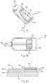
- FIGs. 1A and 1B depict a sensor strip 100, which may be used in the present invention.
- FIG. 1A is a perspective representation of an assembled sensor strip 100 including a sensor base 110, at least partially covered by a lid 120 that includes a vent 130, a sample coverage area 140, and an input end opening 150.
- a partially-enclosed volume 160 (the capillary gap or cap-gap) is formed between the base 110 and the lid 120.
- Other sensor strip designs compatible with the present invention also may be used, such as those described in U.S. Patent Nos. 5,120,420 and 5,798,031 .
- a liquid sample for analysis may be transferred into the cap-gap 160 by introducing the liquid to the opening 150.
- the liquid fills the cap-gap 160 while expelling the previously contained air through the vent 130.
- the cap-gap 160 may contain a composition (not shown) that assists in retaining the liquid sample in the cap-gap.
- Such compositions include water-swellable polymers, such as carboxymethyl cellulose and polyethylene glycol; and porous polymer matrices, such as dextran and polyacrylamide.
- FIG. 1B depicts a top-view of the sensor strip 100, with the lid 120 removed.
- Conductors 170 and 180 may run under a dielectric layer 190 from the opening 150 to a working electrode 175 and a counter electrode 185, respectively.
- the working and counter electrodes 175, 185 may be in substantially the same plane, as depicted in the figure.
- the working and counter electrodes 175, 185 may be separated by greater than 200 or 250 ⁇ m and may be separated from an upper portion of the lid 120 by at least 100 ⁇ m.
- the working and counter electrodes 175, 185 may be separated by less than 200 ⁇ m.
- the dielectric layer 190 may partially cover the electrodes 175, 185 and may be made from any suitable dielectric material, such as an insulating polymer.
- the counter electrode 185 may support the electrochemical activity at the working electrode 175 of the sensor strip 100.
- the potential to support the electrochemical activity at the working electrode 175 may be provided to the sensor system by forming the counter electrode 185 from an inert material, such as carbon, and including a soluble redox species, such as ferricyanide, within the cap-gap 160.
- the potential at the counter electrode 185 may be a reference potential achieved by forming the counter electrode 185 from a redox pair, such as Ag/AgCI, to provide a combined reference-counter electrode.
- the sensor strip 100 may be provided with a third conductor and electrode (not shown) to provide a reference potential to the sensor system.
- FIG. 2A depicts an end-view diagram of the sensor strip depicted in FIG. 1B showing the layer structure of the working electrode 175 and the counter electrode 185.
- the conductors 170 and 180 may lie directly on the base 110.
- Surface conductor layers 270 and 280 optionally may be deposited on the conductors 170 and 180, respectively.
- the surface conductor layers 270, 280 may be made from the same or from different materials.
- the material or materials used to form the conductors 170, 180 and the surface conductor layers 270, 280 may include any electrical conductor. Preferable electrical conductors are non-ionizing, such that the material does not undergo a net oxidation or a net reduction during analysis of the sample.
- the conductors 170, 180 preferably include a thin layer of a metal paste or metal, such as gold, silver, platinum, palladium, copper, or tungsten.
- the surface conductor layers 270, 280 preferably include carbon, gold, platinum, palladium, or combinations thereof. If a surface conductor layer is not present on a conductor, the conductor is preferably made from a non-ionizing material.
- the surface conductor material may be deposited on the conductors 170, 180 by any conventional means compatible with the operation of the sensor strip, including foil deposition, chemical vapor deposition, slurry deposition, and the like.
- the mixture may be applied as an ink to the conductors 170, 180, as described in U.S. Pat. No. 5,798,031 .
- the reagent layers 275 and 285 may be deposited on the conductors 170 and 180, respectively.
- the layers are formed from at least one reagent composition that includes reagents and optionally a binder.
- the binder is preferably a polymeric material that is at least partially water-soluble.
- the binder may form a gel or gel-like material when hydrated by the sample.
- the binder may filter red blood cells.
- Suitable partially water-soluble polymeric materials for use as the binder may include poly(ethylene oxide) (PEO), carboxy methyl cellulose (CMC), polyvinyl alcohol (PVA), hydroxyethylene cellulose (HEC), hydroxypropyl cellulose (HPC), methyl cellulose, ethyl cellulose, ethyl hydroxyethyl cellulose, carboxymethyl ethyl cellulose, polyvinyl pyrrolidone (PVP), polyamino acids, such as polylysine, polystyrene sulfonate, gelatin, acrylic acid, methacrylic acid, starch, maleic anhydride salts thereof, derivatives thereof, and combinations thereof.
- PEO poly(ethylene oxide)
- CMC carboxy methyl cellulose
- PVA polyvinyl alcohol
- HEC hydroxyethylene cellulose
- HPC hydroxypropyl cellulose
- PEO poly(ethylene oxide)
- CMC carboxy methyl cellulose
- PVA polyvinyl alcohol
- the reagent layers 275 and 285 may include the same or different reagents. When including the same reagents, the reagent layers 275 and 285 may be the same layer. In one aspect, the reagents present in the first layer 275 may be selected for use with the working electrode 175, while the reagents present in the second layer 285 may be selected for use with the counter electrode 185. For example, the reagents in the layer 285 may facilitate the free flow of electrons between the sample and the conductor 180. Similarly, the reagents in the layer 275 may facilitate the reaction of the analyte.
- the reagent layer 275 includes an enzyme system specific to the analyte that may facilitate the reaction of the analyte while enhancing the specificity of the sensor system to the analyte, especially in complex biological samples.
- the enzyme system may include one or more enzyme, cofactor, and/or other moiety that participates in the redox reaction with the analyte.
- an alcohol oxidase can be used to provide a sensor strip that is sensitive to the presence of alcohol in a sample.
- glucose dehydrogenase or glucose oxidase may be used to provide a sensor strip that is sensitive to the presence of glucose in a sample. This system could be useful in measuring blood glucose concentrations, for example in patients known or suspected to have diabetes.
- Enzymes for use in the enzyme system include alcohol dehydrogenase, lactate dehydrogenase, ⁇ -hydroxybutyrate dehydrogenase, glucose-6-phosphate dehydrogenase, glucose dehydrogenase, formaldehyde dehydrogenase, malate dehydrogenase, and 3-hydroxysteroid dehydrogenase.
- Preferable enzyme systems are oxygen independent, thus not substantially oxidized by oxygen.
- GDH glucose dehydrogenase
- FAD flavin adenine dinucleotide
- PQQ Pyrroloquinolinequinone
- the co-factor in each of these enzyme systems may either be permanently held by the host enzyme or the co-enzyme and the apo-enzyme may be re-constituted before the enzyme system is added to the reagent composition.
- the co-enzyme also may be independently added to the host enzyme moiety in the reagent composition to assist in the catalytic function of the host enzyme, such as in the cases of nicotinamide adenine dinucleotide NAD/NADH + or nicotinamide adenine dinucleotide phosphate NADP/NADPH + .
- the reagent layer 275 also includes a mediator to more effectively communicate the results of the analyte reaction to the surface conductor 270 and/or the conductor 170.
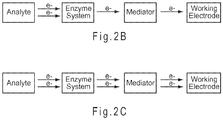
- Mediators may be separated into two groups based on their electrochemical activity.
- One electron transfer mediators are chemical moieties capable of taking on one additional electron during the conditions of the electrochemical reaction, while two electron transfer mediators are chemical moieties capable of taking on two additional electrons during the conditions of the reaction.
- one electron transfer mediators can transfer one electron from the enzyme to the working electrode, while as depicted in FIG. 2C , two electron transfer mediators can transfer two electrons.
- the sensor strips of the present invention may demonstrate an increase in long-term stability. This stability increase may be attributable to a reduction in enzyme denaturization by the mediator during storage. The stability increase also may be attributable to a reduction in the amount of mediator available to oxidize the enzyme during storage.
- Examples of one electron transfer mediators include compounds, such as 1,1'-dimethyl ferrocene, ferrocyanide and ferricyanide, and ruthenium(III) and ruthenium(II) hexaamine.
- Two electron mediators include the organic quinones and hydroquinones, such as phenathroline quinone; phenothiazine and phenoxazine derivatives; 3-(phenylamino)-3H-phenoxazines; phenothiazines; and 7-hydroxy-9,9-dimethyl-9H-acridin-2-one and its derivatives.
- Examples of additional two electron mediators include the electro-active organic molecules described in U.S. Pat. Nos. 5,393,615 ; 5,498,542 ; and 5,520,786 , for example.
- Preferred two electron transfer mediators include 3-phenylimino-3H-phenothiazines (PIPT) and 3-phenylimino-3H-phenoxazines (PIPO). More preferred two electron mediators include the carboxylic acid or salt, such as ammonium salts, of phenothiazine derivatives.
- especially preferred two electron mediators include (E)-2-(3H-phenothiazine-3-ylideneamino)benzene-1,4-disulfonic acid (Structure I), (E)-5-(3H-phenothiazine-3-ylideneamino)isophthalic acid (Structure II), ammonium (E)-3-(3H-phenothiazine-3-ylideneamino)-5-carboxybenzoate (Structure III), and combinations thereof.
- the structural formulas of these mediators are presented below.
- preferred two electron mediators have a redox potential that is at least 100 mV lower, more preferably at least 150 mV lower, than ferricyanide.
- the reagent layers 275, 285 may be deposited by any convenient means, such as printing, liquid deposition, or ink-jet deposition. In one aspect, the layers are deposited by printing. With other factors being equal, the angle of the printing blade may inversely affect the thickness of the reagent layers. For example, when the blade is moved at an approximately 82° angle to the base 110, the layer may have a thickness of approximately 10 ⁇ m. Similarly, when a blade angle of approximately 62° to the base 110 is used, a thicker 30 ⁇ m layer may be produced. Thus, lower blade angles may provide thicker reagent layers. In addition to blade angle, other factors, such as the viscosity of the material being applied as well as the screen-size and emulsion combination, may affect the resulting thickness of the reagent layers 275, 285.
- deposition methods other than printing such as micro-pipetting, ink jetting, or pin-deposition
- These deposition methods generally give the dry reagent layers at micrometer or sub-micrometer thickness, such as 1 -2 ⁇ m.
- pin-deposition methods may provide average reagent layer thicknesses of 1 ⁇ m.
- the thickness of the reagent layer resulting from pin-deposition may be controlled by the amount of polymer included in the reagent composition, with higher polymer content providing thicker reagent layers. Thinner reagent layers may require shorter pulse widths than thicker reagent layers to maintain the desired measurement performance and/or substantially measure analyte within the diffusion barrier layer (DBL).
- DBL diffusion barrier layer
- the working electrode 175 also may include a DBL that is integral to a reagent layer 275 or that is a distinct layer 290, such as depicted in FIG. 2A .
- the DBL may be formed as a combination reagent/DBL on the conductor, as a distinct layer on the conductor, or as a distinct layer on the reagent layer.
- the reagent layer 275 may or may not reside on the DBL 290. Instead of residing on the DBL 290, the reagent layer 275 may reside on any portion of the sensor strip 100 that allows the reagent to solubilize in the sample.
- the reagent layer 175 may reside on the base 110 or on the lid 120.
- the DBL provides a porous space having an internal volume where a measurable species may reside.
- the pores of the DBL may be selected so that the measurable species may diffuse into the DBL, while physically larger sample constituents, such as RBCs, are substantially excluded.
- sample constituents such as RBCs
- conventional sensor strips have used various materials to filter RBCs from the surface of the working electrode, a DBL provides an internal porous space to contain and isolate a portion of the measurable species from the sample.
- any portion of the binder that does not solubilize into the sample prior to the application of an excitation may function as an integral DBL.
- the average initial thickness of a combination DBL/reagent layer is preferably less than 16 or 8 micrometers ( ⁇ m) and more preferably less than 4 ⁇ m. At present, an especially preferred average initial thicknesses of a combination DBL/reagent layer is from 0.25 to 3 ⁇ m or from 0.5 to 2 ⁇ m.
- the desired average initial thickness of a combination DBL/reagent layer may be selected for a specific excitation length on the basis of when the diffusion rate of the measurable species from the DBL to a conductor surface, such as the surface of the conductor 170 or the surface of the surface conductor 270 from FIG. 2A , becomes relatively constant.
- the DBL/reagent layer may have an average initial thickness of 1 ⁇ m or less when combined with an excitation pulse width of 0.25 seconds or less.
- the distinct DBL 290 may include any material that provides the desired pore space, while being partially or slowly soluble in the sample.
- the distinct DBL 290 may include a reagent binder material lacking reagents.
- the distinct DBL 290 may have an average initial thickness of from 1 to 15 ⁇ m, and more preferably from 2 to 5 ⁇ m.
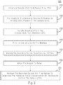
- FIG. 3 represents an electrochemical analysis 300 for determining the presence and optionally the concentration of an analyte 322 in a sample 312.
- the sample 312 is introduced to a sensor strip 314, such as the sensor strip depicted in FIGs. 1A-1B and 2A .
- the reagent layers such as 275 and/or 285 from FIG. 2A , begin to solubilize into the sample 312, thus allowing reaction.
- the initial time delay may be from 0.5 to 5 seconds.
- a more in-depth treatment of initial time delays may be found in U.S. Pat. Nos. 5,620,579 and 5,653,863 .
- a portion of the analyte 322 present in the sample 312 is chemically or biochemically oxidized or reduced in 320, such as by an oxidoreductase.
- electrons may be transferred between the analyte 322 and a mediator 332 in 330, such as through the oxidoreductase.
- the charged mediator 332 is electrochemically excited (oxidized or reduced).
- the sample 312 is whole blood containing glucose oxidized by the PQQ-GDH enzyme system in 320, which then transfers two electrons to reduce a phenothiazine derivative mediator in 330
- the excitation of 340 oxidizes the phenothiazine derivative mediator at the working electrode. In this manner, electrons are selectively transferred from the glucose analyte to the working electrode of the sensor strip where they may be detected by a measurement device.
- the current resulting from the excitation 340 may be recorded during the excitation 340 as a function of time in 350.
- the sample undergoes relaxation.
- the current is not recorded during the relaxation 360.
- the recorded current and time values may be analyzed to determine the presence and/or concentration of the analyte 322 in the sample 312 in 370.
- Amperometric sensor systems apply a potential (voltage) to the sensor strip to excite the measurable species while the current (amperage) is monitored.
- Conventional amperometric sensor systems may maintain the potential while measuring the current for a continuous read pulse length of from 5 to 10 seconds, for example.
- the duty cycles used in the electrochemical analysis 300 replace continuous, long-duration read pulses with multiple excitations and relaxations of short duration.
- multiple excitation and relaxation or "gated" pulse sequences may be found in PCT/US2006/028013, filed July 19, 2006 , entitled “Gated Amperometry.”
- the excitation 340, the recordation 350, and the relaxation 360 constitute a single duty cycle.
- at least 2, 4, 6, or 7 duty cycles are applied during an independently selected 3, 5, 7, 9, or 14 second time period.
- the duty cycles are applied during a 3 to 14 second time period.
- at least 4 duty cycles are applied within 30 seconds, 9 seconds, or less.
- from 2 to 6 duty cycles may be applied within 10 seconds or less.
- from 2 to 4 duty cycles may be applied within 3 to 9 seconds.
- the measurement device may open the circuit through the sensor strip 314, thus allowing the system to relax.
- the current present during the excitation 340 is substantially reduced by at least one-half, preferably by an order of magnitude, and more preferably to zero.
- a zero current state is provided by an open circuit or other method known to those of ordinary skill in the art to provide a substantially zero current flow.
- the relaxation 360 is at least 0.5 or at least 0.2 seconds in duration. In another aspect, the relaxation 360 is from 0.2 to 3 seconds or from 0.5 to 1 second in duration.
- FIGs. 4A-4D depict examples of gated amperometric pulse sequences where multiple duty cycles were applied to the sensor strip after introduction of the sample.
- square-wave pulses were used; however, other wave types compatible with the sensor system and the test sample also may be used.
- Each depicted pulse sequence includes an initial one second excitation pulse 420 followed by multiple 0.25 second excitations 430.
- the initial excitation pulse 420 may be of longer duration than the subsequent excitations 430.
- the initial excitation pulse 420 may range from 0.75 to 3 seconds in duration.
- the length of the excitation pulse 420 may be tailored to oxidize the relatively small amount of enzyme system deposited on the strip.
- the pulse sequence may include the initial excitation pulse 420 having a duration of 2 seconds, followed by an open circuit relaxation of 3 seconds, followed by the subsequent excitation 430 having a duration of 0.125 seconds.
- the multiple excitations 430 may range from 0.01 to 3 seconds in duration. In one aspect, the total excitation length is two seconds or less, thus including the initial one second pulse 420 followed by four of the 0.25 second excitations 430. In another aspect, the total excitation length is 1.5 seconds or less, thus including the initial one second pulse 420 followed by one or two of the 0.25 second excitations 430.
- the pulse sequence may include additional excitations, such as excitation 440 depicted in FIG. 4A .
- the excitations may be of different amplitudes, such as depicted in FIGs. 4C and 4D . In a preferred aspect, when excitations of different amplitudes are used, the difference in amplitudes may be within 500 mV.
- the short excitations may permit the accurate analysis of the sample with reagent compositions having reduced polymer, enzyme system, and mediator concentrations in relation to conventional compositions. Furthermore, the short excitations allow for the analysis to be completed within 8.5 seconds or less, or more preferably, 5 seconds or less from the initial application of a signal to the sensor strip.
- Either short or long excitations may be used.
- the current measurement that the analyte concentration is determined from is taken within 2 seconds or 1 second of the initial application of the signal. More preferably, multiple short excitations are combined with a current measurement taken within 2 seconds, 1 second, or less from the initial application of the signal to determine the analyte concentration of the sample.
- reagent compositions including specific amounts of polymeric binder, enzyme system, and/or mediator were found to reduce hematocrit bias and/or increase long-term stability. While conventional strips are often described in terms of the percent of each reagent composition ingredient, it is the density of each reagent composition ingredient (absolute amount per area) that is relevant to long-term stability.
- the amount of environmentally reduced mediator may be substantially reduced. Thus, providing a beneficial reduction in background current.
- hematocrit biases were larger with the higher polymer concentrations of 2%, 1.5%, and 1% than with a 0.5% (w/w) polymer concentration in the reagent solution when using high enzyme loading. This may be attributable to higher polymer concentrations producing thicker reagent layers that affect hematocrit bias on re-hydration. Thus, as assay times become shorter, rapid re-hydration without an increase in hematocrit bias may be preferred. In this manner, a preferable balance may be reached between the polymer content and enzyme loading of the reagent composition to provide the desired level of hydration during the time of the assay.
- polymer deposition densities of 2 ⁇ g/mm 2 or less may be preferred, with polymer deposition densities from 0.8 to 1.5 ⁇ g/mm 2 being more preferred.
- the amount of the enzyme system present on the working electrode is controlled.
- depositing approximately 0.24 ⁇ L of a solution including 1.2 U of the PQQ-GDH enzyme system, 2.57 ⁇ g of the Structure I mediator, 1.18 ⁇ g of the CMC polymer, and 3.28 ⁇ g of phosphate buffer provides a reagent solution concentration of 5 U/ ⁇ L enzyme system, 24 mM mediator, 0.5% polymer, and 100 mM phosphate buffer.
- Depositing this reagent solution on a deposition area of 1.5 mm 2 including a working electrode area of 1 mm 2 provides an enzyme system deposition density at the working electrode of about 0.8 U/mm 2 (1.2 U/1.5 mm 2 ), a mediator deposition density of 1.72 ⁇ g/mm 2 (2.57 ⁇ g/1.5 mm 2 ), a polymer deposition density of 0.8 ⁇ g/mm 2 , and a phosphate buffer deposition density of 2.2 ⁇ g/mm 2 .
- the enzyme system deposition density will be about 0.3 U/mm 2 .
- the specific activity of an enzyme system may be translated into weight density in terms of ⁇ g/mm 2 . For example, if the activity of an enzyme system is 770 U/mg, the enzyme system's activity density of 0.3 U/mm 2 becomes 0.39 ⁇ g/mm 2 in weight density. Thus, the activity of an enzyme system may be taken into account when determining the deposition density for the enzyme system.
- reagent layers include enzyme deposition densities of 1 to 6 ⁇ g/mm 2 .
- reagent compositions of the present invention include enzyme system deposition densities between 0.42 and 0.8 ⁇ g/mm 2 .
- the deposition solutions of the present invention may include about 4 U/ ⁇ L or less of the enzyme system or may include about 3 U/ ⁇ L or less of the enzyme system.
- 2.2 U/ ⁇ L or less of the PQQ-GDH enzyme system may be included in the reagent solution.
- the reagent composition when the reagent composition is applied to the sensor strip, 1.3 Units or less of the enzyme system may be present on the sensor strip, with from 0.3 to 0.8 Units being more preferred.
- a reagent layer according to the invention comprises from 1.72 to 2 ⁇ g/mm 2 of a mediator.
- two electron mediators are preferable to one electron mediators.
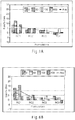
- Table I provides the deposition densities of the polymeric binder, buffer, enzyme system, and mediator components in the reagent compositions used in FIGs. 5A-5E and FIGs. 6A-6C , discussed below.
- the enzyme system deposition density for reagent composition 3 (RC3) at 0.42 ⁇ g/mm 2 is nearly 60 % less than the lowest 1 ⁇ g/mm 2 value of the previously discussed conventional strips.
- RC1, RC2, RC3 and RC4 of Table I only RC3 is according to the present invention.
- the mediator densities given in Table I are approximately one order of magnitude smaller than those of conventional sensor strips.
- the mediator deposition density of RC3 was approximately one-fifth that of a conventional sensor strip. This reduction in the deposition density of the mediator in relation to conventional sensor strips may provide a substantial increase in the long-term stability of RC3, which is a reagent composition according to the present invention.
- Table I CMC, Buffer, PQQ/GDH, Mediator, ⁇ g/mm 2 ⁇ g/mm 2 ⁇ g/mm 2 ⁇ g/mm 2 RC1 1.59 2.17 3.99 1.72 RC2 0.79 2.19 1.07 1.72 RC3 0.79 2.19 0.42 1.72 RC4 0.77 2.22 0.99 1.36
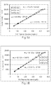
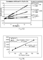
- FIG. 5A depicts the glucose dose response curves at different hematocrit levels in WB samples for the RC2 sensor strip that included 1.2 unit per sensor (U/sensor) at a deposition density of 0.8 U/mm 2 of the PQQ-GDH enzyme.
- FIG. 5B depicts the glucose dose response curves at different hematocrit levels in WB samples for the RC3 sensor strip that included 0.5 U/sensor at a deposition density of 0.3 U/mm 2 of the PQQ-GDH enzyme.
- Both the 1.2 U and 0.5 U sensors delivered hematocrit biases less than ⁇ 5%. However, a difference between the 1.2 U and 0.5 U sensors was observed with regard to the system sensitivity and intercept.
- a reduction in the ratio of intercept-to-slope may be seen for the 0.5 U/sensor of FIG. 5B by comparing the intercept to slope (I/S) ratios, expressed in units of mg/dL, with those of the 1.2 U/sensor of FIG. 5A , with lower ratios representing a reduction in background signal.
- the I/S ratio for the 1.2 U/sensor of FIG. 5A is ⁇ 6 mg/dL
- the I/S ratio for the 0.5 U/sensor of FIG. 5B is ⁇ 0.15 mg/dL, an approximate 40 time reduction at the 40% hematocrit concentration.
- the superior background signal performance of the 0.5 U sensor in relation to a 1.5 U sensor was established.
- the performance characteristic of low background may be provided by relatively low mediator and enzyme deposition densities.
- the performance characteristic of high sensitivity may be provided by optimizing the timing ratio of the excitations and relaxations of the pulse sequence. For example, combining a relatively long relaxation period of 1.5 seconds with a relatively short excitation period of 0.25 second provides a large current density at the surface of the working electrode. Numerically, the relatively small intercept value over the relatively large slope value further improves the I/S.
- preferable sensor performance characteristics small I/S values may be provided by the reagent composition and the measurement method in combination.
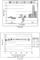
- current imprecision describes the variance between the current measurements of multiple sensor strips.
- current imprecision represents the amount that a recorded current value differs from the mean current value when identical glucose samples are analyzed using multiple sensor strips. The more a recorded current value from a particular strip deviates from the mean value for multiple strips, the poorer the current recorded from that strip correlates with the actual glucose concentration of the sample.
- the current measurement precision may be measured by its imprecision or %-CV i
- the glucose measurement precision also may be measured by its imprecision or %-CV G .
- Table II below, provides slopes (1/G values) calculated with Equation (1) from multiple glucose concentrations in mg/dL.
- 1/57.6 0.0174
- 1/111 0.009
- 1/222.25 0.0045
- 1/444.75 0.0022
- 1/669 0.0015
- the denominators are the plasma glucose concentrations tested.
- the slope value decreases according to equation (1).
- Table II Glucose Concentration in mg/dL I/S Ratio Calculated from Equation (1) Experimentally Determined I/S Ratio 57.6 0.0174 0.0174 111 0.009 0.009 222.25 0.0045 0.0045 444.75 0.0022 0.0022 669 0.0015 0.0015 0.0015
- FIG. 5C presents I/S ratios in mg/dL determined from experimental data.
- the current values were obtained with gated amperometric pulse sequences from WB samples including 40% hematocrit and glucose concentrations of 57.6, 111, 222.25, 444.75, or 669 mg/dL.
- Calibration constants were determined at 4, 5.5, 7, 8.5, 10, 11.5, 13, and 14.5 seconds into the analysis.
- the calculated and experimentally determined values are the same, confirming the ability of Equation (1) to describe the behavior of the sensor strip regarding glucose and current imprecision.
- the typical imprecision in the recorded current values is 3.5%, a system having an I/S ratio of 50 mg/dL results in a glucose imprecision of 7%.
- FIG. 5D shows I/S ratios from 0 to 20 mg/dL for glucose concentrations of 55.375, 112.25, and 433.5 mg/dL determined from sensor strips having reagent compositions RC2, RC3, or RC4 from Table I, above. As the I/S ratios decrease from 20, the imprecision associated with the determined glucose concentration also decrease. Thus, demonstrating that lower I/S ratios are preferred at lower glucose concentrations, as previously discussed.
- sensor strips having an I/S ratio of 20 mg/dL or less are preferred, with those having I/S ratios of 10 mg/dL or less or 6 mg/dL or less being more preferred. At present, strips having an I/S ratio of 1 mg/dL or less are even more preferred.
- FIG. 5E shows the nearly identical hematocrit performance of a sensor system used with plasma and 40 % hematocrit whole blood samples.
- the reagent composition of the sensor strip was RC2, as described in Table I, above.
- the gated pulse sequences in combination with the reagent compositions provide a substantial reduction in the hematocrit effect observed for WB samples.
- FIG. 6A shows the effect of environmental stress on the long-term stability of sensor strips.
- the Y-axis of the graph shows the absolute stability bias in terms of mg/dL for glucose concentrations below 75 mg/dL or the %-bias for glucose concentrations at and above 75 mg/dL for environmentally stressed sensor strips in relation to sensor strips stored at -20° C.
- the stressed sensor strips had been stored at 50° C for two weeks as an accelerated process simulating storage at 25° C for 18 months. Since the mediator density was initially low (1.72 ug/mm 2 ), the average stability bias line in FIG.
- FIG. 6A also established that a reagent composition like RC3 in accord with the present invention provides long-term stability sufficient to not require an initial long oxidative pulse before the analysis, such as that described in U.S. Pat. No. 5,653,863 to Genshaw et al.
- the analysis that generated the data of FIG. 6A had a total duration of 4.5 seconds with a total oxidation time of 1.5 seconds (corresponding to pulse sequence of FIG. 4A ).
- only 30 % of the assay time was spent oxidizing the WB sample in FIG. 6A , compared to ⁇ 67% of the total assay time in the U.S. Pat. No. 5,653,863 analysis (20 seconds of oxidation over a 30 second total analysis time).
- 45% or less of the total assay time is spent oxidizing the sample.
- 35% or less of the total assay time is spent oxidizing the sample.
- FIG. 6B shows the effect of environmental stress on the long-term stability of sensor strips stored at 50° C for four weeks.
- the Y-axis of the graph shows the absolute stability bias in terms of mg/dL for glucose concentrations below 75 mg/dL or the %-bias for glucose concentrations at and above 75 mg/dL for environmentally stressed sensor strips in relation to sensor strips stored at -20° C.
- the increase in stability bias for the 4 week storage period of FIG. 6B in relation to the shorter 2 week storage period of FIG. 6A is seen in the Y-axis values for RC1. Since the mediator density was initially low (1.72 ug/mm 2 ), the average stability bias line in FIG.
- FIG. 6C shows the stability bias for three reagent compositions including the PQQ-GDH enzyme system after 52 weeks at 25° C under 60% relative humidity. Unlike in FIG. 6A and 6B a longer time period at a lower temperature was used to age the strips.
- the bias values for RC2 and RC3 were similar to those observed under accelerated aging, being less than ⁇ 5% on average.
- RC4 showed an increase in bias in relation to the accelerated aging results of FIG. 6A and 6B , increasing to a bit less than the ⁇ 10% level on average. This increase may be attributable to experimental error or to a stability issue with the lot of Structure III mediator used in RC4 under the specific circumstances of this test.
- FIG. 6D shows the stability bias values for sensor strips including RC2 where the data point used to calculate the analyte concentration was taken at a specific time after starting the analysis.
- the 2.75 second line represents the bias/%-bias values of analyte concentration as determined after the first short excitation pulse, such as the excitation 430 in FIG. 4A .
- the 4.375 second line represents the bias/%-bias values of analyte concentration as determined after a second short excitation pulse.
- sensor strips were made using pin-deposition.
- the counter electrode reagent solution was prepared by making a stock solution of 100 mM phosphate buffer in 1% carboxylmethyl cellulose (CMC). Then, enough powdered mediator was dissolved into the buffer/CMC solution to make a final solution of 100 mM mediator in 100 mM phosphate buffer and 1% CMC.
- Pin-deposition was used to deposit the counter electrode reagent solution on one of the carbon surfaces to form the counter electrode.
- the volume delivered by each deposition was from about 0.2 to 0.24 ⁇ L, which spread to cover an area of about 1.5 to 2 mm 2 .
- pin-deposition was used to deposit the working electrode reagent solution on one of the carbon surfaces to form the working electrode.
- the volume for each working electrode deposition was also about 0.2 - 0.24 ⁇ L with a similar solution spread over the carbon to form the working electrode.
- the completed sensor sheet was allowed to air-dry for 15 minutes followed by storage in a desiccated container before final lamination to form the completed sensor strips.
- reagent solution deposition densities of 0.16 ⁇ L/mm 2 (0.24 uL/1.5 mm 2 ) or less at the working electrode are preferred.
- Example 2 Donor Study (exemplary sensor strips SS1 to SS4 are not according to the invention)
- SS1 through which are exemplary sensor strips not according to the invention, as provided in Table III, below.
- Different working and counter electrode reagent compositions were used for SS1 through SS3, while SS4 used a single reagent composition substantially covering both conductors.
- SS1, SS2, and SS3 represent different manufacturing lots using the same reagent amounts.
- the volume of reagent composition deposited on the individual conductors for SS1 through SS3 was about 0.24 ⁇ L, with two deposition areas of about 1.5 mm 2 each.
- the volume of reagent composition deposited to cover both conductors for SS1 was about 0.3 ⁇ L, with a total deposition area of about 3 mm 2 .
- Table III Working Electrode Deposition Counter Electrode Deposition 1.62 ⁇ g/mm 2 CMC 1.11 ⁇ g/mm 2 Buffer 1.62 ⁇ g/mm 2 CMC 0.58 ⁇ g/mm 2 PQQ/GDH Enzyme System 1.11 ⁇ g/mm 2 Buffer 1.39 ⁇ g/mm 2 Structure I Mediator 1.39 ⁇ g/mm 2 Structure I Mediator SS1 pH 7.2 ⁇ 0.1 pH 7.2 ⁇ 0.1 1.62 ⁇ g/mm 2 CMC 1.11 ⁇ g/mm 2 Buffer 1.62 ⁇ g/mm 2 CMC 0.58 ⁇ g/mm 2 PQQ/GDH Enzyme System 1.11 ⁇ g/mm 2 Buffer 1.39 ⁇ g/mm 2 Structure I Mediator 1.39 ⁇ g/mm 2 Structure I Mediator SS2 pH 7.2 ⁇ 0.1 pH 7.2 ⁇ 0.1 1.62 ⁇ g/mm 2
- the samples were analyzed with a pulse sequence having an initial excitation including two short excitations separated by about 0.25 second followed by a 1 second relaxation. After the initial excitation and relaxation, a sequence of three about 0.375 second excitations separated by two about 1 second relaxations was applied. An output current recorded after about 5 seconds from the application of the initial input signal was used to determine the glucose concentration of the sample.
- Tables IV and V below, provide the statistical hematocrit bias results for SS1 through SS4, where two analyses were performed with each type of sensor strip for each of the 21 blood samples to provide 42 readings.
- Table IV shows the slope, intercept and I/S ratio for each sensor strip lot, while Table V shows the percentage of readings having biases within ⁇ 15/ ⁇ 15%, ⁇ 10/ ⁇ 10%, or ⁇ 5/ ⁇ 5% of the YSI reference value.
- For glucose concentrations less than 75 mg/dL bias is expressed as mg/dL (absolute) and for glucose concentrations of 75 mg/dL and greater bias is expressed in percent (relative).
- Table IV establishes that each of the sensor strip lots had an I/S ratio of less than 5 mg/dL, thus establishing the superior background signal performance of the strips.
- the performance of a sensor system may be characterized by the spread of the biases against the reference values. This spread may be measured by the percentage of bias values falling within certain limits, such as ⁇ 15 mg/dL/ ⁇ 15% or ⁇ 10 mg/dL/ ⁇ 10%. The smaller the limit, the better the performance. Multiple factors, including measurement imprecision and the hematocrit effect, will contribute to the bias values. Normally, the performance is judged by having at least 95% of the data population being within a certain performance limit.
- Table V establishes that 100% of the data population from SS1 through SS4 was within the limit of ⁇ 15 mg/dL/ ⁇ 15%. Furthermore, more than 95% of the data population from SS1 through SS4 was within the limit of ⁇ 10 mg/dL/ ⁇ 10%.
- FIG. 7A depicts the dose response curve from the SS1 lot for the 21 whole blood samples.
- the R 2 value of 0.997 established the ability of the strip to provide current values accurately reflecting the actual glucose concentration of the samples.
- FIG. 7B depicts the bias spreads for lots SS1 through SS4 with the 42 readings from 21 samples across the glucose concentration range in the donor study. The figure establishes that 100% of the bias values for all of the sensor strips fell within ⁇ 15%, and that the performance of the SS1 and SS3 manufacturing lots was superior under the conditions of the study with 93% of the data population being within the ⁇ 5% limit.
- the narrow bias spread for the senor strips may be attributed to the enhanced sensitivity and precision, reflected in the small I/S ratios, and to the small hematocrit effect provided by the strips.
- FIG. 7C depicts the hematocrit sensitivity, hematocrit bias in relation to hematocrit content of the sample, obtained from lot SS1 in comparison to a conventional strip having a deposition density of 2.96 ⁇ g/mm 2 for a HEC polymer, 0.69 ⁇ g/mm 2 for a citric buffer, 2.14 ⁇ g/mm 2 for a glucose oxidase enzyme, and 13 ⁇ g/mm 2 for the ferricyanide mediator.
- a hematocrit sensitivity of -0.26 was obtained for the SS1 lot, while the conventional sensor strips had a slope of -1.26, with numerically larger slope values indicating greater hematocrit sensitivity.
- the hematocrit sensitivity of the SS1 lot was approximately 79% less than that provided by the conventional strips.
- System is defined as an electrochemical sensor strip in electrical communication through its conductors with an electronic measurement device, which allows for the quantification of an analyte in a sample.
- Measurement device is defined as an electronic device that can apply an electrical input signal and measure the resulting output signal.
- the measurement device also may include the processing capability to determine the presence and/or concentration of one or more analytes in response to the output signal.
- Analyte is defined as one or more substances present in a sample. An analysis determines the presence and/or concentration of the analyte present in the sample.
- sample is defined as a composition that may contain an unknown amount of the analyte.
- a sample for electrochemical analysis is in liquid form, and preferably the sample is an aqueous mixture.
- a sample may be a biological sample, such as blood, urine, or saliva.
- a sample also may be a derivative of a biological sample, such as an extract, a dilution, a filtrate, or a reconstituted precipitate.
- Conductor is defined as an electrically conductive substance that remains stationary during an electrochemical analysis.
- Examples of conductor materials include solid metals, metal pastes, conductive carbon, conductive carbon pastes, and conductive polymers.
- Non-ionizing material is defined as a material that does not ionize during the electrochemical analysis of an analyte. Examples of non-ionizing materials include carbon, gold, platinum and palladium.
- Measurement performance is defined in terms of accuracy and/or precision. Thus, an increase in measurement performance may be an increase in accuracy and/or precision of the measurement.
- Precision is defined as how close multiple analyte measurements are for the same sample. Precision may be expressed in terms of the spread or variance among multiple measurements in relation to a mean.
- Accuracy is defined as how close the amount of analyte measured by a sensor strip corresponds to the true amount of analyte in the sample. Accuracy may be expressed in terms of bias, with larger bias values reflecting less accuracy.
- Bias is defined as the difference between a measured value and the accepted reference value. Bias may be expressed in terms of “absolute bias” or “relative bias”. Absolute bias may be expressed in the units of the measurement, such as mg/dL, while relative bias may be expressed as a percentage of the absolute bias value over the reference value. Either hematocrit or stability bias may be expressed in terms of an absolute bias value or as a percentage. Hematocrit bias uses an analyte concentration obtained with a reference instrument, such as the YSI 2300 STAT PLUSTM available from YSI Inc., Yellow Springs, Ohio, as the accepted reference value. Stability bias uses an analyte concentration obtained from a sensor strip stored at a temperature of-20° C to substantially reduce thermal alteration of the reagent composition.
- Hematocrit sensitivity is defined as the degree to which changes in the hematocrit level of a sample affect the hematocrit bias values for an analysis.
- Long-term stability is defined in relation to sensor strips packaged, such as with foil and desiccant, and stored at -20° C for 2 or 4 weeks after manufacture versus sensor strips exposed to 50° C for 2 or 4 weeks, respectively. Storage at 50° C for 2 weeks may be considered to approximate 18 months of room temperature storage.
- the average change or deviation for the 0%, 50%, 100%, and 400% hematocrit levels in measurement performance for the 50° C versus the -20° C stored strip indicates the long-term stability drift or "stability bias" for the sensor strip. In this instance, an increase in background signal or bias shows a decrease in measurement performance for the sensor strip.
- an indication of how much bias will increase for sensor strips remaining on store shelves for various time periods may be obtained.
- Mediator is defined as a substance that may be oxidized or reduced and that may transfer one or more electrons.
- a mediator is a reagent in an electrochemical analysis and is not the analyte of interest, but provides for the indirect measurement of the analyte. In a simple system, the mediator undergoes a redox reaction in response to the oxidation or reduction of the analyte. The oxidized or reduced mediator then undergoes the opposite reaction at the working electrode of the sensor strip and is regenerated to its original oxidation number.
- Measurable species is defined as any electrochemically active species that may be oxidized or reduced under an appropriate potential at the electrode surface of an electrochemical sensor strip.
- measurable species include an analyte, a substrate, or a mediator.
- Oxidoreductase is defined as any enzyme that facilitates the oxidation or reduction of a measurable species.
- An oxidoreductase is a reagent.
- the term oxidoreductase includes "oxidases,” which facilitate oxidation reactions where molecular oxygen is the electron acceptor; “reductases,” which facilitate reduction reactions where the analyte is reduced and molecular oxygen is not the analyte; and “dehydrogenases,” which facilitate oxidation reactions in which molecular oxygen is not the electron acceptor. See, for example, Oxford Dictionary of Biochemistry and Molecular Biology, Revised Edition, A.D. Smith, Ed., New York: Oxford University Press (1997) pp. 161, 476, 477, and 560 .
- Electro-active organic molecule is defined as an organic molecule lacking a metal that is capable of undergoing a redox reaction. Electro-active organic molecules can behave as redox species and/or as mediators. Examples of electro-active organic molecules include coenzyme pyrroloquinoline quinone (PQQ), benzoquinones and naphthoquinones, N-oxides, nitroso compounds, hydroxylamines, oxines, flavins, phenazines, phenothiazines, indophenols, and indamines.
- PQQ coenzyme pyrroloquinoline quinone
- Binder is defined as a material that provides physical support and containment to the reagents while having chemical compatibility with the reagents.
- Average initial thickness is defined as the average height of a layer in its dry state prior to introduction of a liquid sample. The term average is used because the top surface of the layer is uneven, having peaks and valleys.
- Deposition density is defined as the mass of a material deposited on an area. For example, when 0.24 ⁇ L of a solution containing 2.57 ⁇ g of a solid is deposited on a surface having an area of 1.5 mm 2 , a deposition density of 1.72 ⁇ g/mm 2 (2.57 ⁇ g/1.5 mm 2 ) results.
- Enzyme unit (U) is defined as the amount of an enzyme system that will catalyze the transformation (oxidation or reduction) of 1 micromole of substrate (analyte) in 1 minute under standard conditions.
- Redox reaction is defined as a chemical reaction between two species involving the transfer of at least one electron from a first species to a second species.
- a redox reaction includes an oxidation and a reduction.
- the oxidation portion of the reaction involves the loss of at least one electron by the first species, and the reduction portion involves the addition of at least one electron to the second species.
- the ionic charge of a species that is oxidized is made more positive by an amount equal to the number of electrons transferred.
- the ionic charge of a species that is reduced is made less positive by an amount equal to the number of electrons transferred.
- Oxidation number is defined as the formal ionic charge of a chemical species, such as an atom.
- a higher oxidation number, such as (III), is more positive, and a lower oxidation number, such as (II), is less positive.
- a neutral species has an ionic charge of zero (0). The oxidation of a species results in an increase in the oxidation number of that species, and reduction of a species results in a decrease in the oxidation number of that species.
- Redox pair is defined as two conjugate species of a chemical substance having different oxidation numbers. Reduction of the species having the higher oxidation number produces the species having the lower oxidation number. Alternatively, oxidation of the species having the lower oxidation number produces the species having the higher oxidation number.
- Oxidizable species is defined as the species of a redox pair having the lower oxidation number, and which is thus capable of being oxidized into the species having the higher oxidation number.
- reducible species is defined as the species of a redox pair having the higher oxidation number, and which is thus capable of being reduced into the species having the lower oxidation number.
- Soluble redox species is defined as a substance that is capable of undergoing oxidation or reduction and that is soluble in water (pH 7, 25° C) at a level of at least 1.0 grams per Liter. Soluble redox species include electro-active organic molecules, organotransition metal complexes, and transition metal coordination complexes. The term “soluble redox species” excludes elemental metals and lone metal ions, especially those that are insoluble or sparingly soluble in water.
- Organictransition m etal complex also referred to as “OTM complex” is defined as a complex where a transition metal is bonded to at least one carbon atom through a sigma bond (formal charge of -1 on the carbon atom sigma bonded to the transition metal) or a pi bond (formal charge of 0 on the carbon atoms pi bonded to the transition metal).
- OTM complex is defined as a complex where a transition metal is bonded to at least one carbon atom through a sigma bond (formal charge of -1 on the carbon atom sigma bonded to the transition metal) or a pi bond (formal charge of 0 on the carbon atoms pi bonded to the transition metal).
- ferrocene is an OTM complex with two cyclopentadienyl (Cp) rings, each bonded through its five carbon atoms to an iron center by two pi bonds and one sigma bond.
- OTM complex ferricyanide (III) and its reduced ferrocyanide (II) counterpart, where six cyano ligands (formal charge of -1 on each of the 6 ligands) are sigma bonded to an iron center through the carbon atoms of the cyano groups.
- Coordinating complex is defined as a complex having well-defined coordination geometry, such as octahedral or square planar geometry. Unlike OTM complexes, which are defined by their bonding, coordination complexes are defined by their geometry. Thus, coordination complexes may be OTM complexes (such as the previously mentioned ferricyanide), or complexes where non-metal atoms other than carbon, such as heteroatoms including nitrogen, sulfur, oxygen, and phosphorous, are datively bonded to the transition metal center.
- OTM complexes such as the previously mentioned ferricyanide
- non-metal atoms other than carbon such as heteroatoms including nitrogen, sulfur, oxygen, and phosphorous
- ruthenium hexaamine is a coordination complex having a well-defined octahedral geometry where six NH 3 ligands (formal charge of 0 on each of the 6 ligands) are datively bonded to the ruthenium center.
- organotransition metal complexes, coordination complexes, and transition metal bonding may be found in Collman et al., Principles and Applications of Organotransition Metal Chemistry (1987 ) and Miessler & Tarr, Inorganic Chemistry (1991 ).
- Handheld device is defined as a device that may be held in a human hand and is portable.
- An example of a handheld device is the measurement device accompanying Ascensia® Elite Blood Glucose Monitoring System, available from Bayer HealthCare, LLC, Elkhart, IN.
- On is defined as “above” and is relative to the orientation being described. For example, if a first element is deposited over at least a portion of a second element, the first element is said to be “deposited on” the second. In another example, if a first element is present above at least a portion of a second element, the first element is said to be “on” the second.
- the use of the term “on” does not exclude the presence of substances between the upper and lower elements being described.
- a first element may have a coating over its top surface, yet a second element over at least a portion of the first element and its top coating can be described as "on” the first element.
- the use of the term “on” may or may not mean that the two elements being related are in physical contact with each other.
Claims (16)
- Ein elektrochemischer Sensorstreifen (100) mit einer ersten Elektrode (175),
einer zweiten Elektrode (185) und einem Deckel (120) auf einer Grundplatte (110), gekennzeichnet durch:
eine erste Elektrode (175) auf der Grundplatte (110) mit wenigstens einer ersten Schicht auf einem ersten Leiter (270), wobei die erste Schicht eine Reagenzschicht (275) mit 1,72 bis 2 µg/mm2 eines Mediators und ein Enzymsystem mit einer Abscheidungsdichte von 0,42 bis 0,8 µg/mm2 umfasst;
wobei der Streifen (100) dazu eingerichtet ist, einen bestimmten Analytenkonzentrationswert bereitzustellen. - Der elektrochemische Sensorstreifen (100) aus Anspruch 1, ferner dadurch gekennzeichnet, dass die zweite Elektrode eine zweite Schicht auf einem zweiten Leiter (280) umfasst, wobei die zweite Schicht eine weitere Reagenzschicht (285) umfasst, die sich in ihrer Zusammensetzung von der Reagenzschicht (275) der ersten Schicht unterscheidet.
- Der elektrochemische Sensorstreifen (100) aus einem der vorhergehenden Ansprüche, wobei die erste und zweite Elektrode (175, 185) von einem oberen Abschnitt des Deckels (120) um mindestens 100 µm beabstandet sind.
- Der elektrochemische Sensorstreifen (100) aus einem der vorhergehenden Ansprüche, wobei die durchschnittliche Anfangsdicke der Reagenzschicht (275, 285) weniger als 8 µm beträgt und wobei die Reagenzschicht (275, 285) eine Abscheidungsdichte von höchstens 0,2 µL/mm2 aus einer Reagenzlösung aufweist.
- Der elektrochemische Sensorstreifen (100) aus einem der vorhergehenden Ansprüche, wobei die Reagenzschicht (275, 285) ein polymeres Bindemittel umfasst, ausgewählt aus der Gruppe bestehend aus Poly(ethylenoxid), Polyvinylalkohol, Hydroxyehtylencellulose, Carboxymethylcellulose und Kombinationen derselben, und wobei die Abscheidungsdichte des polymeren Bindemittels höchstens 2 µg/mm2 auf dem ersten Leiter beträgt.
- Der elektrochemische Sensorstreifen (100) aus einem der vorhergehenden Ansprüche, wobei die Reagenzschicht (275, 285) ein teilweise wasserlösliches polymeres Bindemittel umfasst, das bei Hydratation ein gelartiges Material bildet.
- Der elektrochemische Sensorstreifen (100) aus einem der vorhergehenden Ansprüche, wobei die Reagenzschicht höchstens 1,3 Einheiten eines Enzymsystems umfasst.
- Der elektrochemische Sensorstreifen (100) aus einem der vorhergehenden Ansprüche, wobei der Mediator ein Zwei-Elektronen-Transfer-Mediator ist, und wobei der Zwei-Elektronen-Transfer-Mediator mindestens einer aus 3 Phenylimino-3H-phenothiazinen, 3 Phenylimino-3H-phenoxazinen, Salzen davon, Säuren davon und Derivaten davon ist.
- Der elektrochemische Sensorstreifen (100) aus einem der vorhergehenden Ansprüche, wobei der Mediator ein Redoxpotential um mindestens 100 mV niedriger als Ferricyanid aufweist.
- Ein Verfahren zur Bestimmung der Konzentration eines Analyten in einer Probe mit einem elektrochemischen Sensorstreifen (100) nach einem der vorhergehenden Ansprüche,
gekennzeichnet durch:Umsetzen der Probe mit einer Reagenzschicht (275), wobei die Reagenzschicht (275) 1,72 bis 2 µg/mm2 eines Mediators und ein Enzymsystem mit einer Abscheidungsdichte von 0,42 bis 0,8 µg/mm2 umfasst;Anwenden einer Impulsfolge auf eine Analyt beinhaltende Probe, wobei die Impulsfolge mindestens 3 Arbeitszyklen innerhalb von 30 Sekunden, vorzugsweise mindestens 3 Arbeitszyklen innerhalb von 9 Sekunden oder stärker bevorzugt mindestens 3 Arbeitszyklen in höchstens 5 Sekunden umfasst, und wobei jeder Arbeitszyklus eine Anregung und eine Entspannung umfasst;Messen mindestens einer der Anregungen; und Bestimmen der Konzentration des Analyten in der Probe aus der Messung. - Das Verfahren aus dem vorhergehenden Anspruch, ferner gekennzeichnet durch das Bestimmen der Konzentration des Analyten in der Probe aus einer Strommessung, die innerhalb von 2 Sekunden nach Anwendung der Impulsfolge durchgeführt wird.
- Das Verfahren aus einem der beiden vorhergehenden Ansprüche, wobei die Anregungen jeweils eine Dauer von 0,01 bis 3 Sekunden oder vorzugsweise höchstens 2 Sekunden aufweisen.
- Das Verfahren aus einem der drei vorhergehenden Ansprüche, wobei die Anregungen eine summierte Dauer von höchstens 10 Sekunden aufweisen, oder wobei die Anregungen höchstens 45% der Zeit der Impulsfolge umfassen.
- Das Verfahren aus einem der vier vorhergehenden Ansprüche, wobei die Anregungen Amplituden mit einer Differenz innerhalb von 500 mV sind.
- Das Verfahren aus einem der fünf vorhergehenden Ansprüche, wobei die Entspannungen jeweils eine Dauer von 0,2 bis 3 Sekunden aufweisen.
- Das Verfahren aus einem der sechs vorhergehenden Ansprüche, wobei die Impulsfolge eine initiale Anregung von 0,75 bis 3 Sekunden Dauer umfasst und wobei die initiale Anregung länger ist als die Anregungen der mindestens 3 Arbeitszyklen.
Priority Applications (1)
| Application Number | Priority Date | Filing Date | Title |
|---|---|---|---|
| EP19173431.8A EP3543348B1 (de) | 2006-09-22 | 2007-09-09 | Biosensorsystem mit verbesserter stabilität und hämatokrit-ausführung |
Applications Claiming Priority (2)
| Application Number | Priority Date | Filing Date | Title |
|---|---|---|---|
| US84668806P | 2006-09-22 | 2006-09-22 | |
| PCT/US2007/077955 WO2008036516A1 (en) | 2006-09-22 | 2007-09-09 | Biosensor system having enhanced stability and hematocrit performance |
Related Child Applications (2)
| Application Number | Title | Priority Date | Filing Date |
|---|---|---|---|
| EP19173431.8A Division EP3543348B1 (de) | 2006-09-22 | 2007-09-09 | Biosensorsystem mit verbesserter stabilität und hämatokrit-ausführung |
| EP19173431.8A Division-Into EP3543348B1 (de) | 2006-09-22 | 2007-09-09 | Biosensorsystem mit verbesserter stabilität und hämatokrit-ausführung |
Publications (2)
| Publication Number | Publication Date |
|---|---|
| EP2089531A1 EP2089531A1 (de) | 2009-08-19 |
| EP2089531B1 true EP2089531B1 (de) | 2019-07-10 |
Family
ID=38777711
Family Applications (2)
| Application Number | Title | Priority Date | Filing Date |
|---|---|---|---|
| EP19173431.8A Active EP3543348B1 (de) | 2006-09-22 | 2007-09-09 | Biosensorsystem mit verbesserter stabilität und hämatokrit-ausführung |
| EP07814768.3A Active EP2089531B1 (de) | 2006-09-22 | 2007-09-09 | Biosensorsystem mit verbesserter stabilität und hämatokrit-ausführung |
Family Applications Before (1)
| Application Number | Title | Priority Date | Filing Date |
|---|---|---|---|
| EP19173431.8A Active EP3543348B1 (de) | 2006-09-22 | 2007-09-09 | Biosensorsystem mit verbesserter stabilität und hämatokrit-ausführung |
Country Status (13)
| Country | Link |
|---|---|
| US (6) | US7862696B2 (de) |
| EP (2) | EP3543348B1 (de) |
| JP (2) | JP5395665B2 (de) |
| CN (1) | CN101517093B (de) |
| BR (1) | BRPI0717430A2 (de) |
| CA (1) | CA2664186C (de) |
| ES (1) | ES2748685T3 (de) |
| HK (1) | HK1136605A1 (de) |
| MX (1) | MX2009002830A (de) |
| NO (1) | NO20091572L (de) |
| RU (1) | RU2450263C2 (de) |
| TW (1) | TW200829214A (de) |
| WO (1) | WO2008036516A1 (de) |
Families Citing this family (47)
| Publication number | Priority date | Publication date | Assignee | Title |
|---|---|---|---|---|
| RU2413002C2 (ru) * | 2004-12-13 | 2011-02-27 | Байер Хелткэр Ллк | Самостоятельно ограничивающие размер композиции и тестирующие устройства для измерения содержания анализируемых веществ в биологических жидкостях |
| US9636450B2 (en) | 2007-02-19 | 2017-05-02 | Udo Hoss | Pump system modular components for delivering medication and analyte sensing at seperate insertion sites |
| US7826879B2 (en) | 2006-02-28 | 2010-11-02 | Abbott Diabetes Care Inc. | Analyte sensors and methods of use |
| WO2008036516A1 (en) | 2006-09-22 | 2008-03-27 | Bayer Healthcare Llc | Biosensor system having enhanced stability and hematocrit performance |
| WO2008154225A2 (en) | 2007-06-06 | 2008-12-18 | Bayer Healthcare Llc | Microdeposition system for a biosensor |
| CN101896619B (zh) * | 2007-12-10 | 2017-04-05 | 安晟信医疗科技控股公司 | 速读门控电流分析法 |
| US8876755B2 (en) | 2008-07-14 | 2014-11-04 | Abbott Diabetes Care Inc. | Closed loop control system interface and methods |
| JP5773883B2 (ja) * | 2008-12-08 | 2015-09-02 | バイエル・ヘルスケア・エルエルシーBayer HealthCareLLC | バイオセンサのための低全塩試薬組成物およびシステム |
| CN104825171B (zh) * | 2009-02-26 | 2017-08-04 | 雅培糖尿病护理公司 | 改进的分析物传感器及其制造和使用方法 |
| EP3714788B8 (de) * | 2009-02-26 | 2023-06-14 | Abbott Diabetes Care, Inc. | Verfahren zur herstellung von verbesserten analytsensoren |
| EP4289355A3 (de) | 2009-07-23 | 2024-02-28 | Abbott Diabetes Care Inc. | System zur kontinuierlichen analytmessung |
| WO2011012848A1 (en) * | 2009-07-27 | 2011-02-03 | Suresensors Ltd | Improvements relating to sensor devices |
| US8691075B2 (en) * | 2009-12-30 | 2014-04-08 | Roche Diagnostics Operations, Inc. | Method for measuring analyte concentration in a liquid sample |
| IN2012DN05912A (de) * | 2010-01-22 | 2015-09-18 | Bayer Healthcare Llc | |
| US9233788B2 (en) | 2010-01-22 | 2016-01-12 | Bayer Healthcare Llc | Biosensor desiccant system having enhanced measurement performance |
| CN103210310B (zh) * | 2010-06-07 | 2015-03-18 | 拜尔健康护理有限责任公司 | 包含次级输出信号的基于斜率的补偿 |
| EP2659268A4 (de) | 2010-12-31 | 2017-01-18 | Cilag GmbH International | Systeme und verfahren für hochpräzise analytmessung |
| TWI565943B (zh) * | 2011-07-22 | 2017-01-11 | 拜耳保健公司 | 具有增進測量性能之生物感測器乾燥劑系統 |
| US20130052673A1 (en) * | 2011-08-26 | 2013-02-28 | Lifescan Scotland Ltd. | Use of enzyme emulsion thickness to affect calibration code factors in test strip manufacturing |
| CN103946701A (zh) * | 2011-11-18 | 2014-07-23 | 株式会社村田制作所 | 物质的测定方法 |
| US9903830B2 (en) * | 2011-12-29 | 2018-02-27 | Lifescan Scotland Limited | Accurate analyte measurements for electrochemical test strip based on sensed physical characteristic(s) of the sample containing the analyte |
| US9535027B2 (en) * | 2012-07-25 | 2017-01-03 | Abbott Diabetes Care Inc. | Analyte sensors and methods of using same |
| GB201223166D0 (en) * | 2012-12-21 | 2013-02-06 | Alere Switzerland Gmbh | Test strip |
| US9097659B2 (en) | 2013-03-14 | 2015-08-04 | Bayer Healthcare Llc | Maintaining electrode function during manufacture with a protective layer |
| JP6352954B2 (ja) | 2013-03-15 | 2018-07-04 | エフ.ホフマン−ラ ロシュ アーゲーF. Hoffmann−La Roche Aktiengesellschaft | 電気化学的な分析物測定において回復パルスからの情報を使用する方法およびデバイス、装置とそれらを組み込むシステム |
| EP3388823A1 (de) | 2013-03-15 | 2018-10-17 | Roche Diabetes Care GmbH | Verfahren zur skalierung von daten zur konstruktion von biosensoralgorithmen sowie vorrichtungen, einrichtungen und systeme damit |
| WO2014140172A1 (en) | 2013-03-15 | 2014-09-18 | Roche Diagnostics Gmbh | Methods of failsafing electrochemical measurements of an analyte as well as devices, apparatuses and systems incorporating the same |
| WO2014140178A1 (en) * | 2013-03-15 | 2014-09-18 | Roche Diagnostics Gmbh | Methods of electrochemically measuring an analyte with a test sequence having a pulsed dc block as well as devices, apparatuses and systems incorporating the same |
| WO2014140173A1 (en) | 2013-03-15 | 2014-09-18 | Roche Diagnostics Gmbh | Descriptor-based methods of electrochemically measuring an analyte as well as devices, apparatuses and systems incoporating the same |
| JP6356707B2 (ja) | 2013-03-15 | 2018-07-11 | エフ.ホフマン−ラ ロシュ アーゲーF. Hoffmann−La Roche Aktiengesellschaft | 電気化学的測定中に高抗酸化物質レベルを検出してそれから分析物濃度をフェイルセイフする方法並びにそれを組み込んだデバイス、装置、及びシステム |
| US9459231B2 (en) | 2013-08-29 | 2016-10-04 | Lifescan Scotland Limited | Method and system to determine erroneous measurement signals during a test measurement sequence |
| US9243276B2 (en) | 2013-08-29 | 2016-01-26 | Lifescan Scotland Limited | Method and system to determine hematocrit-insensitive glucose values in a fluid sample |
| RU2552942C2 (ru) * | 2013-10-28 | 2015-06-10 | Федеральное государственное бюджетное образовательное учреждение высшего профессионального образования "Уральский государственный экономический университет" (ФГБОУ ВПО "УрГЭУ") | Устройство для неинвазивного потенциометрического определения оксидантной/антиоксидантной активности биологических тканей |
| WO2015137929A1 (en) * | 2014-03-11 | 2015-09-17 | Google Inc. | Sensor |
| BR112017001444B1 (pt) | 2014-08-25 | 2022-08-16 | F. Hoffmann-La Roche Ag | Método para detectar pelo menos um analito em uma amostra de teste, elemento sensor, dispositivo de teste, sistema de teste, uso do elemento sensor e portador de dados |
| US10501770B2 (en) | 2015-02-05 | 2019-12-10 | The Regents Of The University Of California | Multiple-use renewable electrochemical sensors based on direct drawing of enzymatic inks |
| GB201507509D0 (en) * | 2015-04-30 | 2015-06-17 | Inside Biometrics Ltd | Electrochemical Test Device |
| WO2017058806A1 (en) * | 2015-09-28 | 2017-04-06 | The Regents Of The University Of California | Wearable sensor arrays for in-situ body fluid analysis |
| JP6403653B2 (ja) * | 2015-11-05 | 2018-10-10 | シラグ・ゲーエムベーハー・インターナショナルCilag GMBH International | 高精度分析物測定用システム及び方法 |
| CA3028348A1 (en) * | 2016-07-12 | 2018-01-18 | Ascensia Diabetes Care Holdings Ag | Method for electrochemical analysis by use of alternating output signals from two electrodes |
| KR102372113B1 (ko) * | 2016-10-05 | 2022-03-07 | 에프. 호프만-라 로슈 아게 | 다중 분석물 진단 테스트 엘리먼트들을 위한 검출 시약들 및 전극 배열들, 그리고 그것을 사용하는 방법들 |
| JP6680702B2 (ja) * | 2017-01-27 | 2020-04-15 | シラグ・ゲーエムベーハー・インターナショナルCilag GMBH International | 高精度分析物測定用システム及び方法 |
| KR102197061B1 (ko) * | 2017-10-23 | 2020-12-30 | 주식회사 비바이오 | 커피링 효과에 강인한 바이오센서 |
| JP6609001B2 (ja) * | 2018-06-04 | 2019-11-20 | シラグ・ゲーエムベーハー・インターナショナル | 高精度分析物測定用システム及び方法 |
| WO2021133144A1 (ko) | 2019-12-26 | 2021-07-01 | 주식회사 아이센스 | 신규한 유기 전자전달매개체 및 이를 포함하는 장치 |
| CA3200244A1 (en) * | 2020-12-15 | 2022-06-23 | Tianmei Ouyang | Nad(p) depot for nad(p)-dependent enzyme-based sensors |
| WO2023009720A1 (en) * | 2021-07-28 | 2023-02-02 | Cleu Diagnostics, Llc | Oxygen scavengers for electrochemical biosensors |
Citations (2)
| Publication number | Priority date | Publication date | Assignee | Title |
|---|---|---|---|---|
| US6120676A (en) * | 1997-02-06 | 2000-09-19 | Therasense, Inc. | Method of using a small volume in vitro analyte sensor |
| US20050016844A1 (en) * | 2003-06-20 | 2005-01-27 | Burke David W. | Reagent stripe for test strip |
Family Cites Families (72)
| Publication number | Priority date | Publication date | Assignee | Title |
|---|---|---|---|---|
| US36268A (en) * | 1862-08-26 | Improvement in horse-rakes | ||
| US3791933A (en) * | 1971-02-25 | 1974-02-12 | Geomet | Rapid methods for assay of enzyme substrates and metabolites |
| US3791988A (en) * | 1972-03-23 | 1974-02-12 | Hoffmann La Roche | Diagnostic test for glucose |
| GB1595616A (en) | 1977-01-21 | 1981-08-12 | Hitachi Ltd | Air conditioning system |
| US5682884A (en) * | 1983-05-05 | 1997-11-04 | Medisense, Inc. | Strip electrode with screen printing |
| CA1219040A (en) | 1983-05-05 | 1987-03-10 | Elliot V. Plotkin | Measurement of enzyme-catalysed reactions |
| US4746607A (en) * | 1985-02-07 | 1988-05-24 | Eastman Kodak Company | Use of substituted quinone electron transfer agents in analytical determinations |
| GB8626081D0 (en) | 1986-10-31 | 1986-12-03 | Unilever Plc | Printing processes |
| US5126247A (en) | 1988-02-26 | 1992-06-30 | Enzymatics, Inc. | Method, system and devices for the assay and detection of biochemical molecules |
| US5108564A (en) * | 1988-03-15 | 1992-04-28 | Tall Oak Ventures | Method and apparatus for amperometric diagnostic analysis |
| US5128015A (en) * | 1988-03-15 | 1992-07-07 | Tall Oak Ventures | Method and apparatus for amperometric diagnostic analysis |
| USRE36268E (en) | 1988-03-15 | 1999-08-17 | Boehringer Mannheim Corporation | Method and apparatus for amperometric diagnostic analysis |
| DE68924026T3 (de) | 1988-03-31 | 2008-01-10 | Matsushita Electric Industrial Co., Ltd., Kadoma | Biosensor und dessen herstellung. |
| DE3826922A1 (de) * | 1988-08-09 | 1990-02-22 | Boehringer Mannheim Gmbh | Verfahren zur kolorimetrischen bestimmung eines analyten mittels enzymatischer oxidation |
| US5320725A (en) * | 1989-08-02 | 1994-06-14 | E. Heller & Company | Electrode and method for the detection of hydrogen peroxide |
| US5264104A (en) * | 1989-08-02 | 1993-11-23 | Gregg Brian A | Enzyme electrodes |
| US5262035A (en) * | 1989-08-02 | 1993-11-16 | E. Heller And Company | Enzyme electrodes |
| KR0171222B1 (ko) * | 1989-12-15 | 1999-02-18 | 스티브 올드함 | 산화 환원 조정시약 및 바이오센서 |
| US5288387A (en) * | 1990-06-12 | 1994-02-22 | Daikin Industries, Ltd. | Apparatus for maintaining the activity of an enzyme electrode |
| US5545519A (en) * | 1990-09-13 | 1996-08-13 | Victoria University Of Manchester | Electrolytic analytical methods |
| JPH04278450A (ja) * | 1991-03-04 | 1992-10-05 | Adam Heller | バイオセンサー及び分析物を分析する方法 |
| US5393615A (en) | 1994-02-03 | 1995-02-28 | Miles Inc. | Mediators suitable for the electrochemical regeneration of NADH, NADPH or analogs thereof |
| US5762770A (en) * | 1994-02-21 | 1998-06-09 | Boehringer Mannheim Corporation | Electrochemical biosensor test strip |
| US5498542A (en) | 1994-09-29 | 1996-03-12 | Bayer Corporation | Electrode mediators for regeneration of NADH and NADPH |
| US6153069A (en) * | 1995-02-09 | 2000-11-28 | Tall Oak Ventures | Apparatus for amperometric Diagnostic analysis |
| US5631863A (en) * | 1995-02-14 | 1997-05-20 | Honeywell Inc. | Random access memory cell resistant to radiation induced upsets |
| US5582697A (en) * | 1995-03-17 | 1996-12-10 | Matsushita Electric Industrial Co., Ltd. | Biosensor, and a method and a device for quantifying a substrate in a sample liquid using the same |
| US5620579A (en) | 1995-05-05 | 1997-04-15 | Bayer Corporation | Apparatus for reduction of bias in amperometric sensors |
| US5520786A (en) | 1995-06-06 | 1996-05-28 | Bayer Corporation | Mediators suitable for the electrochemical regeneration of NADH, NADPH or analogs thereof |
| US5695947A (en) * | 1995-06-06 | 1997-12-09 | Biomedix, Inc. | Amperometric cholesterol biosensor |
| AUPN363995A0 (en) * | 1995-06-19 | 1995-07-13 | Memtec Limited | Electrochemical cell |
| US5628890A (en) | 1995-09-27 | 1997-05-13 | Medisense, Inc. | Electrochemical sensor |
| US5631371A (en) * | 1995-11-22 | 1997-05-20 | Bayer Corporation | Method for the preparation of substituted 3-(phenylimino)-3H-phenothiazines and phenoxazines |
| US5708247A (en) | 1996-02-14 | 1998-01-13 | Selfcare, Inc. | Disposable glucose test strips, and methods and compositions for making same |
| JP3370504B2 (ja) | 1996-03-13 | 2003-01-27 | 松下電器産業株式会社 | バイオセンサ |
| DE69730376T2 (de) * | 1996-06-01 | 2005-08-18 | Agfa-Gevaert | (Photo)thermographisches Material mit verbesserten Transporteigenschaften |
| JPH10104192A (ja) * | 1996-09-30 | 1998-04-24 | Matsushita Electric Ind Co Ltd | バイオセンサ |
| US5798031A (en) | 1997-05-12 | 1998-08-25 | Bayer Corporation | Electrochemical biosensor |
| US5997817A (en) * | 1997-12-05 | 1999-12-07 | Roche Diagnostics Corporation | Electrochemical biosensor test strip |
| US6134461A (en) * | 1998-03-04 | 2000-10-17 | E. Heller & Company | Electrochemical analyte |
| US6475372B1 (en) | 2000-02-02 | 2002-11-05 | Lifescan, Inc. | Electrochemical methods and devices for use in the determination of hematocrit corrected analyte concentrations |
| US6229390B1 (en) * | 1999-03-09 | 2001-05-08 | Tripath Technology, Inc. | Methods and apparatus for noise shaping a mixed signal power output |
| US6258229B1 (en) * | 1999-06-02 | 2001-07-10 | Handani Winarta | Disposable sub-microliter volume sensor and method of making |
| US6287451B1 (en) * | 1999-06-02 | 2001-09-11 | Handani Winarta | Disposable sensor and method of making |
| CA2305922C (en) * | 1999-08-02 | 2005-09-20 | Bayer Corporation | Improved electrochemical sensor design |
| US6413398B1 (en) * | 1999-09-13 | 2002-07-02 | Her Majesty The Queen In Right Of Canada, As Represented By The Canadian Food Inspection Agency | Method for electrochemical detection |
| DE60024965T2 (de) * | 1999-10-05 | 2006-07-13 | Matsushita Electric Industrial Co., Ltd., Kadoma | Glukosesensor |
| DE60019547T2 (de) * | 1999-12-27 | 2005-10-06 | Matsushita Electric Industrial Co., Ltd., Kadoma | Biosensor |
| CN1187610C (zh) * | 2000-03-29 | 2005-02-02 | 松下电器产业株式会社 | 生物传感器 |
| US6494873B2 (en) * | 2000-03-31 | 2002-12-17 | Sca Hygiene Products | Absorbent article provided with a belt |
| JP4653870B2 (ja) * | 2000-05-31 | 2011-03-16 | 株式会社テクノメデイカ | コレステロール測定用センサ |
| US7163616B2 (en) | 2001-09-14 | 2007-01-16 | Bayer Corporation | Reagents and methods for detecting analytes, and devices comprising reagents for detecting analytes |
| US7291256B2 (en) * | 2002-09-12 | 2007-11-06 | Lifescan, Inc. | Mediator stabilized reagent compositions and methods for their use in electrochemical analyte detection assays |
| KR100554649B1 (ko) | 2003-06-09 | 2006-02-24 | 주식회사 아이센스 | 전기화학적 바이오센서 |
| GB0314357D0 (en) * | 2003-06-19 | 2003-07-23 | Pii Ltd | Electromagnetic acoustic transducer |
| JP2005083965A (ja) * | 2003-09-10 | 2005-03-31 | Rohm Co Ltd | 酵素機能電極及びコレステロールセンサ |
| JP4458802B2 (ja) * | 2003-10-02 | 2010-04-28 | パナソニック株式会社 | 血液中のグルコースの測定方法およびそれに用いるセンサ |
| ES2366030T3 (es) | 2003-10-24 | 2011-10-14 | Bayer Healthcare, Llc | Biosensor electroquímico enzimático. |
| JP4088312B2 (ja) | 2003-10-30 | 2008-05-21 | アークレイ株式会社 | バイオセンサおよびその製造方法 |
| KR101049330B1 (ko) | 2003-12-04 | 2011-07-13 | 파나소닉 주식회사 | 헤마토크릿의 측정 방법 및 그것에 이용하는 센서 및 측정장치 |
| EP3273232A2 (de) * | 2003-12-04 | 2018-01-24 | Panasonic Healthcare Holdings Co., Ltd. | Verfahren zur messung einer blutkomponente, sensor zur verwendung in dem verfahren und messgerät |
| WO2005073708A2 (de) * | 2004-01-29 | 2005-08-11 | Siemens Aktiengesellschaft | Verfahren zur messung der konzentration oder konzentrationsänderung einer redoxaktiven substanz und zugehörige vorrichtung |
| US7138041B2 (en) | 2004-02-23 | 2006-11-21 | General Life Biotechnology Co., Ltd. | Electrochemical biosensor by screen printing and method of fabricating same |
| EP3115777B1 (de) | 2004-04-19 | 2020-01-08 | PHC Holdings Corporation | Verfahren zur messung von blutbestandteilen |
| CA2887517C (en) * | 2004-10-12 | 2017-09-12 | Bayer Healthcare Llc | Concentration determination in a diffusion barrier layer |
| KR20070114802A (ko) * | 2005-03-04 | 2007-12-04 | 바이엘 헬쓰케어, 엘엘씨 | 전기화학적 바이오센서에서 효소 활성의 안정화 |
| AU2006272909B2 (en) * | 2005-07-20 | 2013-02-07 | Bayer Healthcare Llc | Gated amperometry |
| AU2006297572B2 (en) * | 2005-09-30 | 2012-11-15 | Ascensia Diabetes Care Holdings Ag | Gated Voltammetry |
| JP5111388B2 (ja) | 2005-11-14 | 2013-01-09 | バイエル・ヘルスケア・エルエルシー | セルロースポリマーを有する試験センサ試薬 |
| WO2008036516A1 (en) | 2006-09-22 | 2008-03-27 | Bayer Healthcare Llc | Biosensor system having enhanced stability and hematocrit performance |
| CN101896619B (zh) * | 2007-12-10 | 2017-04-05 | 安晟信医疗科技控股公司 | 速读门控电流分析法 |
| CN101896618B (zh) | 2007-12-10 | 2015-04-22 | 拜尔健康护理有限责任公司 | 检测分析物的试剂和方法 |
-
2007
- 2007-09-09 WO PCT/US2007/077955 patent/WO2008036516A1/en active Application Filing
- 2007-09-09 MX MX2009002830A patent/MX2009002830A/es active IP Right Grant
- 2007-09-09 JP JP2009529302A patent/JP5395665B2/ja active Active
- 2007-09-09 CN CN200780034836.1A patent/CN101517093B/zh active Active
- 2007-09-09 EP EP19173431.8A patent/EP3543348B1/de active Active
- 2007-09-09 BR BRPI0717430-6A patent/BRPI0717430A2/pt not_active IP Right Cessation
- 2007-09-09 CA CA2664186A patent/CA2664186C/en not_active Expired - Fee Related
- 2007-09-09 RU RU2009115202/28A patent/RU2450263C2/ru active
- 2007-09-09 ES ES07814768T patent/ES2748685T3/es active Active
- 2007-09-09 EP EP07814768.3A patent/EP2089531B1/de active Active
- 2007-09-10 US US11/853,010 patent/US7862696B2/en active Active
- 2007-09-14 TW TW096134412A patent/TW200829214A/zh unknown
-
2009
- 2009-04-21 NO NO20091572A patent/NO20091572L/no not_active Application Discontinuation
-
2010
- 2010-02-24 HK HK10101922.9A patent/HK1136605A1/zh not_active IP Right Cessation
- 2010-11-22 US US12/951,382 patent/US8702965B2/en active Active
-
2013
- 2013-03-26 JP JP2013064125A patent/JP5738914B2/ja active Active
- 2013-11-14 US US14/079,922 patent/US8728299B2/en active Active
-
2014
- 2014-04-14 US US14/252,226 patent/US9239312B2/en active Active
-
2015
- 2015-12-10 US US14/964,721 patent/US9459229B2/en active Active
-
2016
- 2016-08-23 US US15/244,212 patent/US10261044B2/en active Active
Patent Citations (2)
| Publication number | Priority date | Publication date | Assignee | Title |
|---|---|---|---|---|
| US6120676A (en) * | 1997-02-06 | 2000-09-19 | Therasense, Inc. | Method of using a small volume in vitro analyte sensor |
| US20050016844A1 (en) * | 2003-06-20 | 2005-01-27 | Burke David W. | Reagent stripe for test strip |
Also Published As
| Publication number | Publication date |
|---|---|
| US20140061062A1 (en) | 2014-03-06 |
| US10261044B2 (en) | 2019-04-16 |
| CN101517093A (zh) | 2009-08-26 |
| US9459229B2 (en) | 2016-10-04 |
| JP5738914B2 (ja) | 2015-06-24 |
| CA2664186A1 (en) | 2008-03-27 |
| TW200829214A (en) | 2008-07-16 |
| ES2748685T3 (es) | 2020-03-17 |
| EP3543348A1 (de) | 2019-09-25 |
| WO2008036516A1 (en) | 2008-03-27 |
| US8702965B2 (en) | 2014-04-22 |
| RU2009115202A (ru) | 2010-10-27 |
| JP2013145243A (ja) | 2013-07-25 |
| US20140305808A1 (en) | 2014-10-16 |
| EP2089531A1 (de) | 2009-08-19 |
| US7862696B2 (en) | 2011-01-04 |
| US20160084792A1 (en) | 2016-03-24 |
| US20080156662A1 (en) | 2008-07-03 |
| US8728299B2 (en) | 2014-05-20 |
| JP5395665B2 (ja) | 2014-01-22 |
| MX2009002830A (es) | 2009-05-28 |
| US20110115504A1 (en) | 2011-05-19 |
| EP3543348B1 (de) | 2020-11-18 |
| CA2664186C (en) | 2021-02-23 |
| US9239312B2 (en) | 2016-01-19 |
| RU2450263C2 (ru) | 2012-05-10 |
| US20160356738A1 (en) | 2016-12-08 |
| JP2010504524A (ja) | 2010-02-12 |
| CN101517093B (zh) | 2016-01-06 |
| HK1136605A1 (zh) | 2010-07-02 |
| NO20091572L (no) | 2009-04-21 |
| BRPI0717430A2 (pt) | 2013-11-12 |
Similar Documents
| Publication | Publication Date | Title |
|---|---|---|
| US10261044B2 (en) | Electrochemical test sensor | |
| US9546974B2 (en) | Concentration determination in a diffusion barrier layer | |
| AU2016202064B2 (en) | Concentration determination in a diffusion barrier layer | |
| AU2014274588B2 (en) | Concentration determination in a diffusion barrier layer |
Legal Events
| Date | Code | Title | Description |
|---|---|---|---|
| PUAI | Public reference made under article 153(3) epc to a published international application that has entered the european phase |
Free format text: ORIGINAL CODE: 0009012 |
|
| 17P | Request for examination filed |
Effective date: 20090422 |
|
| AK | Designated contracting states |
Kind code of ref document: A1 Designated state(s): AT BE BG CH CY CZ DE DK EE ES FI FR GB GR HU IE IS IT LI LT LU LV MC MT NL PL PT RO SE SI SK TR |
|
| DAX | Request for extension of the european patent (deleted) | ||
| 17Q | First examination report despatched |
Effective date: 20121018 |
|
| RAP1 | Party data changed (applicant data changed or rights of an application transferred) |
Owner name: BAYER HEALTHCARE LLC |
|
| RAP1 | Party data changed (applicant data changed or rights of an application transferred) |
Owner name: ASCENSIA DIABETES CARE HOLDINGS AG |
|
| STAA | Information on the status of an ep patent application or granted ep patent |
Free format text: STATUS: EXAMINATION IS IN PROGRESS |
|
| REG | Reference to a national code |
Ref country code: DE Ref legal event code: R079 Ref document number: 602007058803 Country of ref document: DE Free format text: PREVIOUS MAIN CLASS: C12Q0001000000 Ipc: G01N0027327000 |
|
| RIC1 | Information provided on ipc code assigned before grant |
Ipc: C12Q 1/00 20060101ALI20181123BHEP Ipc: G01N 27/327 20060101AFI20181123BHEP Ipc: G01N 33/543 20060101ALI20181123BHEP Ipc: G01N 33/49 20060101ALI20181123BHEP |
|
| GRAP | Despatch of communication of intention to grant a patent |
Free format text: ORIGINAL CODE: EPIDOSNIGR1 |
|
| STAA | Information on the status of an ep patent application or granted ep patent |
Free format text: STATUS: GRANT OF PATENT IS INTENDED |
|
| INTG | Intention to grant announced |
Effective date: 20190205 |
|
| RIN1 | Information on inventor provided before grant (corrected) |
Inventor name: SPRADLIN, HOPE Inventor name: WU, HUAN-PING Inventor name: NELSON, CHRISTINE, D. Inventor name: MAURER, ERIC |
|
| GRAS | Grant fee paid |
Free format text: ORIGINAL CODE: EPIDOSNIGR3 |
|
| GRAA | (expected) grant |
Free format text: ORIGINAL CODE: 0009210 |
|
| STAA | Information on the status of an ep patent application or granted ep patent |
Free format text: STATUS: THE PATENT HAS BEEN GRANTED |
|
| AK | Designated contracting states |
Kind code of ref document: B1 Designated state(s): AT BE BG CH CY CZ DE DK EE ES FI FR GB GR HU IE IS IT LI LT LU LV MC MT NL PL PT RO SE SI SK TR |
|
| REG | Reference to a national code |
Ref country code: GB Ref legal event code: FG4D |
|
| REG | Reference to a national code |
Ref country code: CH Ref legal event code: EP Ref country code: AT Ref legal event code: REF Ref document number: 1154111 Country of ref document: AT Kind code of ref document: T Effective date: 20190715 |
|
| REG | Reference to a national code |
Ref country code: DE Ref legal event code: R096 Ref document number: 602007058803 Country of ref document: DE |
|
| REG | Reference to a national code |
Ref country code: IE Ref legal event code: FG4D |
|
| REG | Reference to a national code |
Ref country code: NL Ref legal event code: MP Effective date: 20190710 |
|
| REG | Reference to a national code |
Ref country code: LT Ref legal event code: MG4D |
|
| REG | Reference to a national code |
Ref country code: AT Ref legal event code: MK05 Ref document number: 1154111 Country of ref document: AT Kind code of ref document: T Effective date: 20190710 |
|
| PG25 | Lapsed in a contracting state [announced via postgrant information from national office to epo] |
Ref country code: FI Free format text: LAPSE BECAUSE OF FAILURE TO SUBMIT A TRANSLATION OF THE DESCRIPTION OR TO PAY THE FEE WITHIN THE PRESCRIBED TIME-LIMIT Effective date: 20190710 Ref country code: PT Free format text: LAPSE BECAUSE OF FAILURE TO SUBMIT A TRANSLATION OF THE DESCRIPTION OR TO PAY THE FEE WITHIN THE PRESCRIBED TIME-LIMIT Effective date: 20191111 Ref country code: AT Free format text: LAPSE BECAUSE OF FAILURE TO SUBMIT A TRANSLATION OF THE DESCRIPTION OR TO PAY THE FEE WITHIN THE PRESCRIBED TIME-LIMIT Effective date: 20190710 Ref country code: SE Free format text: LAPSE BECAUSE OF FAILURE TO SUBMIT A TRANSLATION OF THE DESCRIPTION OR TO PAY THE FEE WITHIN THE PRESCRIBED TIME-LIMIT Effective date: 20190710 Ref country code: BG Free format text: LAPSE BECAUSE OF FAILURE TO SUBMIT A TRANSLATION OF THE DESCRIPTION OR TO PAY THE FEE WITHIN THE PRESCRIBED TIME-LIMIT Effective date: 20191010 Ref country code: NL Free format text: LAPSE BECAUSE OF FAILURE TO SUBMIT A TRANSLATION OF THE DESCRIPTION OR TO PAY THE FEE WITHIN THE PRESCRIBED TIME-LIMIT Effective date: 20190710 Ref country code: LT Free format text: LAPSE BECAUSE OF FAILURE TO SUBMIT A TRANSLATION OF THE DESCRIPTION OR TO PAY THE FEE WITHIN THE PRESCRIBED TIME-LIMIT Effective date: 20190710 |
|
| PG25 | Lapsed in a contracting state [announced via postgrant information from national office to epo] |
Ref country code: IS Free format text: LAPSE BECAUSE OF FAILURE TO SUBMIT A TRANSLATION OF THE DESCRIPTION OR TO PAY THE FEE WITHIN THE PRESCRIBED TIME-LIMIT Effective date: 20191110 Ref country code: GR Free format text: LAPSE BECAUSE OF FAILURE TO SUBMIT A TRANSLATION OF THE DESCRIPTION OR TO PAY THE FEE WITHIN THE PRESCRIBED TIME-LIMIT Effective date: 20191011 Ref country code: LV Free format text: LAPSE BECAUSE OF FAILURE TO SUBMIT A TRANSLATION OF THE DESCRIPTION OR TO PAY THE FEE WITHIN THE PRESCRIBED TIME-LIMIT Effective date: 20190710 |
|
| REG | Reference to a national code |
Ref country code: ES Ref legal event code: FG2A Ref document number: 2748685 Country of ref document: ES Kind code of ref document: T3 Effective date: 20200317 |
|
| PG25 | Lapsed in a contracting state [announced via postgrant information from national office to epo] |
Ref country code: TR Free format text: LAPSE BECAUSE OF FAILURE TO SUBMIT A TRANSLATION OF THE DESCRIPTION OR TO PAY THE FEE WITHIN THE PRESCRIBED TIME-LIMIT Effective date: 20190710 |
|
| PG25 | Lapsed in a contracting state [announced via postgrant information from national office to epo] |
Ref country code: PL Free format text: LAPSE BECAUSE OF FAILURE TO SUBMIT A TRANSLATION OF THE DESCRIPTION OR TO PAY THE FEE WITHIN THE PRESCRIBED TIME-LIMIT Effective date: 20190710 Ref country code: EE Free format text: LAPSE BECAUSE OF FAILURE TO SUBMIT A TRANSLATION OF THE DESCRIPTION OR TO PAY THE FEE WITHIN THE PRESCRIBED TIME-LIMIT Effective date: 20190710 Ref country code: DK Free format text: LAPSE BECAUSE OF FAILURE TO SUBMIT A TRANSLATION OF THE DESCRIPTION OR TO PAY THE FEE WITHIN THE PRESCRIBED TIME-LIMIT Effective date: 20190710 Ref country code: RO Free format text: LAPSE BECAUSE OF FAILURE TO SUBMIT A TRANSLATION OF THE DESCRIPTION OR TO PAY THE FEE WITHIN THE PRESCRIBED TIME-LIMIT Effective date: 20190710 |
|
| PG25 | Lapsed in a contracting state [announced via postgrant information from national office to epo] |
Ref country code: SK Free format text: LAPSE BECAUSE OF FAILURE TO SUBMIT A TRANSLATION OF THE DESCRIPTION OR TO PAY THE FEE WITHIN THE PRESCRIBED TIME-LIMIT Effective date: 20190710 Ref country code: CZ Free format text: LAPSE BECAUSE OF FAILURE TO SUBMIT A TRANSLATION OF THE DESCRIPTION OR TO PAY THE FEE WITHIN THE PRESCRIBED TIME-LIMIT Effective date: 20190710 Ref country code: MC Free format text: LAPSE BECAUSE OF FAILURE TO SUBMIT A TRANSLATION OF THE DESCRIPTION OR TO PAY THE FEE WITHIN THE PRESCRIBED TIME-LIMIT Effective date: 20190710 Ref country code: IS Free format text: LAPSE BECAUSE OF FAILURE TO SUBMIT A TRANSLATION OF THE DESCRIPTION OR TO PAY THE FEE WITHIN THE PRESCRIBED TIME-LIMIT Effective date: 20200224 |
|
| REG | Reference to a national code |
Ref country code: DE Ref legal event code: R097 Ref document number: 602007058803 Country of ref document: DE |
|
| PLBE | No opposition filed within time limit |
Free format text: ORIGINAL CODE: 0009261 |
|
| STAA | Information on the status of an ep patent application or granted ep patent |
Free format text: STATUS: NO OPPOSITION FILED WITHIN TIME LIMIT |
|
| PG2D | Information on lapse in contracting state deleted |
Ref country code: IS |
|
| PG25 | Lapsed in a contracting state [announced via postgrant information from national office to epo] |
Ref country code: LU Free format text: LAPSE BECAUSE OF NON-PAYMENT OF DUE FEES Effective date: 20190909 Ref country code: IE Free format text: LAPSE BECAUSE OF NON-PAYMENT OF DUE FEES Effective date: 20190909 |
|
| REG | Reference to a national code |
Ref country code: BE Ref legal event code: MM Effective date: 20190930 |
|
| 26N | No opposition filed |
Effective date: 20200603 |
|
| PG25 | Lapsed in a contracting state [announced via postgrant information from national office to epo] |
Ref country code: SI Free format text: LAPSE BECAUSE OF FAILURE TO SUBMIT A TRANSLATION OF THE DESCRIPTION OR TO PAY THE FEE WITHIN THE PRESCRIBED TIME-LIMIT Effective date: 20190710 Ref country code: BE Free format text: LAPSE BECAUSE OF NON-PAYMENT OF DUE FEES Effective date: 20190930 |
|
| PGFP | Annual fee paid to national office [announced via postgrant information from national office to epo] |
Ref country code: CH Payment date: 20201002 Year of fee payment: 14 Ref country code: ES Payment date: 20201001 Year of fee payment: 14 |
|
| PG25 | Lapsed in a contracting state [announced via postgrant information from national office to epo] |
Ref country code: CY Free format text: LAPSE BECAUSE OF FAILURE TO SUBMIT A TRANSLATION OF THE DESCRIPTION OR TO PAY THE FEE WITHIN THE PRESCRIBED TIME-LIMIT Effective date: 20190710 |
|
| PG25 | Lapsed in a contracting state [announced via postgrant information from national office to epo] |
Ref country code: MT Free format text: LAPSE BECAUSE OF FAILURE TO SUBMIT A TRANSLATION OF THE DESCRIPTION OR TO PAY THE FEE WITHIN THE PRESCRIBED TIME-LIMIT Effective date: 20190710 Ref country code: HU Free format text: LAPSE BECAUSE OF FAILURE TO SUBMIT A TRANSLATION OF THE DESCRIPTION OR TO PAY THE FEE WITHIN THE PRESCRIBED TIME-LIMIT; INVALID AB INITIO Effective date: 20070909 |
|
| REG | Reference to a national code |
Ref country code: CH Ref legal event code: PL |
|
| PG25 | Lapsed in a contracting state [announced via postgrant information from national office to epo] |
Ref country code: LI Free format text: LAPSE BECAUSE OF NON-PAYMENT OF DUE FEES Effective date: 20210930 Ref country code: CH Free format text: LAPSE BECAUSE OF NON-PAYMENT OF DUE FEES Effective date: 20210930 |
|
| REG | Reference to a national code |
Ref country code: ES Ref legal event code: FD2A Effective date: 20221028 |
|
| PG25 | Lapsed in a contracting state [announced via postgrant information from national office to epo] |
Ref country code: ES Free format text: LAPSE BECAUSE OF NON-PAYMENT OF DUE FEES Effective date: 20210910 |
|
| P01 | Opt-out of the competence of the unified patent court (upc) registered |
Effective date: 20230512 |
|
| PGFP | Annual fee paid to national office [announced via postgrant information from national office to epo] |
Ref country code: IT Payment date: 20230921 Year of fee payment: 17 Ref country code: GB Payment date: 20230927 Year of fee payment: 17 |
|
| PGFP | Annual fee paid to national office [announced via postgrant information from national office to epo] |
Ref country code: FR Payment date: 20230925 Year of fee payment: 17 Ref country code: DE Payment date: 20230927 Year of fee payment: 17 |