EP2089192B1 - Mass oscillating unit for hand-held machine tools with a striking device - Google Patents
Mass oscillating unit for hand-held machine tools with a striking device Download PDFInfo
- Publication number
- EP2089192B1 EP2089192B1 EP07803568A EP07803568A EP2089192B1 EP 2089192 B1 EP2089192 B1 EP 2089192B1 EP 07803568 A EP07803568 A EP 07803568A EP 07803568 A EP07803568 A EP 07803568A EP 2089192 B1 EP2089192 B1 EP 2089192B1
- Authority
- EP
- European Patent Office
- Prior art keywords
- unit
- mass
- counterweight
- power tool
- counter
- Prior art date
- Legal status (The legal status is an assumption and is not a legal conclusion. Google has not performed a legal analysis and makes no representation as to the accuracy of the status listed.)
- Not-in-force
Links
Images


Classifications
-
- B—PERFORMING OPERATIONS; TRANSPORTING
- B25—HAND TOOLS; PORTABLE POWER-DRIVEN TOOLS; MANIPULATORS
- B25D—PERCUSSIVE TOOLS
- B25D17/00—Details of, or accessories for, portable power-driven percussive tools
- B25D17/24—Damping the reaction force
-
- B—PERFORMING OPERATIONS; TRANSPORTING
- B25—HAND TOOLS; PORTABLE POWER-DRIVEN TOOLS; MANIPULATORS
- B25D—PERCUSSIVE TOOLS
- B25D11/00—Portable percussive tools with electromotor or other motor drive
- B25D11/06—Means for driving the impulse member
- B25D11/12—Means for driving the impulse member comprising a crank mechanism
- B25D11/125—Means for driving the impulse member comprising a crank mechanism with a fluid cushion between the crank drive and the striking body
-
- B—PERFORMING OPERATIONS; TRANSPORTING
- B25—HAND TOOLS; PORTABLE POWER-DRIVEN TOOLS; MANIPULATORS
- B25D—PERCUSSIVE TOOLS
- B25D2216/00—Details of portable percussive machines with superimposed rotation, the rotational movement of the output shaft of a motor being modified to generate axial impacts on the tool bit
- B25D2216/0069—Locking means
-
- B—PERFORMING OPERATIONS; TRANSPORTING
- B25—HAND TOOLS; PORTABLE POWER-DRIVEN TOOLS; MANIPULATORS
- B25D—PERCUSSIVE TOOLS
- B25D2217/00—Details of, or accessories for, portable power-driven percussive tools
- B25D2217/0073—Arrangements for damping of the reaction force
- B25D2217/0076—Arrangements for damping of the reaction force by use of counterweights
- B25D2217/0084—Arrangements for damping of the reaction force by use of counterweights being fluid-driven
-
- B—PERFORMING OPERATIONS; TRANSPORTING
- B25—HAND TOOLS; PORTABLE POWER-DRIVEN TOOLS; MANIPULATORS
- B25D—PERCUSSIVE TOOLS
- B25D2217/00—Details of, or accessories for, portable power-driven percussive tools
- B25D2217/0073—Arrangements for damping of the reaction force
- B25D2217/0076—Arrangements for damping of the reaction force by use of counterweights
- B25D2217/0088—Arrangements for damping of the reaction force by use of counterweights being mechanically-driven
-
- B—PERFORMING OPERATIONS; TRANSPORTING
- B25—HAND TOOLS; PORTABLE POWER-DRIVEN TOOLS; MANIPULATORS
- B25D—PERCUSSIVE TOOLS
- B25D2217/00—Details of, or accessories for, portable power-driven percussive tools
- B25D2217/0073—Arrangements for damping of the reaction force
- B25D2217/0076—Arrangements for damping of the reaction force by use of counterweights
- B25D2217/0092—Arrangements for damping of the reaction force by use of counterweights being spring-mounted
-
- B—PERFORMING OPERATIONS; TRANSPORTING
- B25—HAND TOOLS; PORTABLE POWER-DRIVEN TOOLS; MANIPULATORS
- B25D—PERCUSSIVE TOOLS
- B25D2250/00—General details of portable percussive tools; Components used in portable percussive tools
- B25D2250/131—Idling mode of tools
-
- B—PERFORMING OPERATIONS; TRANSPORTING
- B25—HAND TOOLS; PORTABLE POWER-DRIVEN TOOLS; MANIPULATORS
- B25D—PERCUSSIVE TOOLS
- B25D2250/00—General details of portable percussive tools; Components used in portable percussive tools
- B25D2250/231—Sleeve details
Definitions
- the invention relates to a handheld power tool impact device according to the preamble of claim 1.
- a handheld power tool percussion device with a striking mechanism arrangement with at least one unit which is intended to generate a counterforce to a force resulting from the percussion mechanism, the unit being formed by a mass vibration unit is, wherein the mass vibration unit comprises a counterweight mass for striking mechanism arrangement, wherein the unit has a locking unit which is provided for securing the counterweight in an idle position, wherein the locking unit has at least one locking element and a fixing element and wherein for securing the counterweight in the axial direction of the Arresting element in a locking recess, which is arranged within the counter-vibration mass, is movable, wherein the fixing element is arranged movable within the locking element.
- an advantageous reduction of vibrations on a housing of a hand tool machine with a hand tool machine impact device, which are caused by the generation of a shock pulse of the impact mechanism, can be achieved.
- the generated counterforce and the force resulting from the hammer mechanism are preferably aligned in opposite directions, so that an advantageous and at least partial cancellation of the forces can be achieved in a vibration reduction and thus particularly advantageous a virtually vibration-free guidance for an operator of the power tool can be achieved.
- the unit is intended to generate the counterforce within a large speed range of a drive unit or a high impact frequency range of Schlagwerkan instructive so that the counterforce generated in the direction and time can be advantageously matched to a compression force of Schlagtechnikan für a maximum vibration reduction can be achieved
- the unit may be designed as a mechanical, an electrical and / or a magnetic and / or a pneumatic unit and / or as further, the expert appears reasonable unit and thereby a mechanical, electrical and / or magnetic, etc. counterforce to generate resultant force of the percussion arrangement.
- the unit is formed by a mass vibration unit, which structurally simple means of a mechanical excitation, especially if the unit formed by the mass vibration unit has a counterweight, a counterforce generated by a counter-vibration to the compression force of the hammer mechanism can be achieved.
- the unit has at least one spring means which supports the counterweight mass, whereby, after an excitation of the counterweight mass, an advantageous return of the counterweight mass to the rest position or starting position can be achieved and thus a renewed and in particular periodic excitation of the counterweight mass can be achieved.
- the spring means supports the mating mass on a housing of the power tool.
- the unit has at least one excitation means which can be driven by means of a drive means of the hammer mechanism, whereby a structurally simple adaptation or coupling of the generated counter-vibration or the generated counterforce to a rotational speed of the drive unit or to a beat frequency of the striking mechanism arrangement can be achieved.
- the excitation means can be formed by an electrical, a magnetic and / or a mechanical excitation means and / or further excitation means which appear expedient to the person skilled in the art.
- the countervibration mass can be excited by means of the excitation means counter to a drive direction of the striking mechanism arrangement, whereby an advantageous cancellation of the counterforce and the resulting force of the striking mechanism arrangement can be achieved.
- the excitation means is formed by an eccentric wheel, so that in particular a periodic excitation of the countervibration mass is achieved can, wherein the eccentric wheel is preferably coupled to a beat frequency of the striking mechanism arrangement or a rotational speed of the drive unit.
- the unit has a locking unit which is provided for securing the counterweight mass in an idling position.
- a locking unit which is provided for securing the counterweight mass in an idling position.
- a handheld power tool with a handheld power tool striking device is proposed, and thus an advantageous ease of operation with a low and / or particularly advantageous with a virtually vanishing resulting vibration of the power tool housing for an operator of the power tool is achieved.
- FIG. 1 is a handheld power tool 36a shown with a handheld power tool impactor device 10a.
- the handheld power tool impact device 10a ( FIG. 2 ) comprises a striking mechanism assembly 12a and a unit 14a formed by a mass vibration unit.
- the percussion arrangement 12a is for generating a impact impulse for a tool 40a, which is located in a tool holder 42a of the handheld power tool 36a ( FIG. 1 ), and for this purpose has a piston 44a, a pneumatic element 46a, a racket 48a and a firing pin, not shown.
- the percussion arrangement 12a comprises a hammer tube 32a, in which the piston 44a and the racket 48a along a drive direction 26a of the striking mechanism arrangement 12a are mounted axially movable. Between the piston 44a and the beater 48a, the pneumatic element 46a formed by an air cushion is arranged ( FIG. 2 ).
- a drive torque is generated by a drive unit of the handheld power tool 36a (not shown here in detail and formed by an electric motor).
- the drive unit transmits a drive torque to a drive means 38a formed by a drive shaft, which is oriented perpendicular to the drive direction 26a of the striking mechanism arrangement 12a ( FIG. 2 ).
- a drive shaft which is oriented perpendicular to the drive direction 26a of the striking mechanism arrangement 12a ( FIG. 2 ).
- this has an eccentric drive unit 52a with a non-rotatably connected to the drive shaft eccentric 54a and a bolt-shaped eccentric pin 56a.
- the eccentric pin 56a is aligned perpendicular to a main extension surface 58a of the eccentric wheel 54a and perpendicular to the drive direction 26a of the hammer mechanism 12a and arranged in a region of the eccentric wheel 54a, which is arranged outside a drive shaft 60a of the eccentric wheel 54a formed by a rotation axis.
- the eccentric pin 56a is connected to the piston 44a via a drive rod 62a of the striking mechanism assembly 12a.
- the mass vibration unit is disposed in a portion of the portable power tool 36a, that of the drive shaft From the perspective, the drive direction 26a of the hammer mechanism 12a is opposite.
- the mass vibration unit has a counterweight 20a, a spring means 22a and an excitation means 24a formed by an eccentric wheel 28a.
- the eccentric 28a is driven via the drive shaft of the drive unit, which is provided for driving the hammer mechanism assembly 12a, and is rotationally connected thereto.
- the eccentric wheel 28a has a cam-shaped, asymmetrical shape of a main extension surface 64a, which, relative to a circular shape, in a center has a recess 66a for rotationally fixed attachment to the drive shaft ( FIG. 3 ).
- the eccentric 28a and a drive cam 68a of the mass vibration unit and the eccentric 54a and the eccentric pin 56a of the striking mechanism 12a run in the direction of rotation 72a with a phase shift of 180 ° about the drive shaft, so that the drive cam 68a of the eccentric 28a of the mass vibration unit in one of Drive direction 26a opposite end position is when the eccentric pin 56a of the eccentric 54a of the percussion mechanism assembly 12a is in an in the drive direction 26a facing end position ( FIG. 2 ).
- the counterweight 20a is moved counter to a drive direction 26a of the hammer mechanism 12a.
- the counterweight 20a is moved counter to a spring force of a spring means 22a, wherein the spring means 22a, the counterweight 20a is supported on a housing 70a of the power tool 36a.
- a maximum of a compression force acts formed force 18a of the percussion mechanism 12a against the drive direction 26a of the striking mechanism assembly 12a.
- a counterforce 16a is generated which reaches a maximum, due to the arrangement of the mass vibration unit, almost simultaneously to the maximum resultant force 18a of the impact mechanism 12a.
- the opposing force 16a of the mass vibration unit is in the opposite direction to the resultant force 18a of the percussion mechanism 12a, so that the resultant force 18a of the percussion mechanism 12a and the counterforce 16a in the area of the drive shaft cancel as far as possible and resulting oscillations of the handheld power tool 36a are at least reduced and / or avoided ( FIG. 2 ).
- the spring means 22a of the mass vibration unit causes an automatic return of the counterweight 20a in the initial situation, the counterweight 20a after a periodic rotation about the axis of rotation of the drive shaft of the cam-shaped eccentric 28a again against the spring force of the spring means 22a and against the drive direction 26a of the striking mechanism 12a move.
- the counterforce 16a of the mass vibration unit is adapted to a momentary impact frequency of the striking mechanism arrangement 12a or to a direction and time of the force 18a resulting from the impact mechanism arrangement 12a.
- the spring means 22a causes an increased inertia when accelerating the counterweight 20a and the counterforce 16a thus acts over a longer period against the resulting force 18a of the impact mechanism assembly 12a.
- FIGS. 4 to 12 Alternative examples or embodiments of the invention are shown. Substantially identical components, features and functions are basically numbered by the same reference numerals. To distinguish the examples, however, the reference numerals of the embodiments, the letters a to f are added. The following description is essentially limited to the differences from the example in FIGS FIGS. 1 to 3 , wherein with respect to the same components, features and functions on the description of the example in the FIGS. 1 to 3 can be referenced.
- FIGS. 4 to 6 show an alternative portable power tool impactor apparatus 10b.
- An eccentric 28b for exciting a counterweight 20b is also provided for driving a striking mechanism 12b.
- the eccentric wheel 28b has two eccentric pins 56b, 74b which are arranged on mutually opposite edge regions 76b, 78b of the eccentric wheel 28b.
- the eccentric pin 74b extends for excitation of the counterweight 20b on a side facing away from the eccentric pin 56b to drive the striking mechanism 12b side of the eccentric 28b perpendicular to a main extension surface 64b of the eccentric 28b.
- another spring means 80b is arranged on a side facing in a drive direction 26b side.
- the spring means 80b allows a muted coupling of the eccentric pin 74b to the counterweight mass 20b, wherein the eccentric pin 74b has a direction of movement in a direction of rotation 72b of the eccentric 28b and a drive shaft.
- the eccentric pin 74b coupled to a Timing to the spring element 80b, in which a compression force is built up in the hammer mechanism assembly 12b.
- a compression force or a resultant force 18b increases against the drive direction 26b in the striking mechanism arrangement 12b and at the same time the countervailing mass 20b is pressed counter to the drive direction 26b and thus a counterforce 16b is generated by an acceleration of the countervailing mass 20b.
- a maximum force 18b results from the striking mechanism arrangement 12b against the drive direction 26b and from the mass vibration unit results in a maximum counterforce 16b in the direction of the drive direction 26b, wherein the force 18b and the counterforce 16b cancel each other at least partially.
- the mass vibration unit on a stop means 82b which is arranged in the drive direction 26b of the striking mechanism assembly 12b after the other spring means 80b.
- the stop means 82b prevents excessive back movement of the counterweight 20b by means of a spring means 22b and positions the counterweight 20b in a starting position for a renewed excitation by means of the eccentric wheel 28b.
- the stop means 82b is additionally coupled to the counterweight 20b with a spring element 84b, to prevent undesirable abutment of the spring means 80b and / or the countermass 20b on the stop means 82b.
- the counterweight 20b is positioned by means of the spring means 22b for support on the housing 70b of the power tool and the spring element 84b in a starting position for a new excitation.
- a handheld power tool impactor device 10c is shown with a locking unit 34c which is provided for securing a counterweight mass 20c in an idling position.
- the locking unit 34c has a spring element 86c, a locking element 88c, a fixing element 90c and a retaining ring 92c arranged on a hammer tube 32c.
- the spring element 86c supports the locking element 88c on a housing 70c of a hand-held power tool and is arranged in a chiseling operation in a prestressed position.
- the fixing element 90c is fixedly connected to the retaining ring 92c with an end 94c pointing in a drive direction 26c and movably arranged with the other end 96c within the locking element 88c.
- the locking element 88c has a recess 98c, which tapers in a direction which extends counter to the drive direction 26c, in which the fixing element 90c is arranged to be axially movable.
- the spring element 86c causes a displacement of the fixing element 90c in the drive direction 26c or a displacement of the tapered recess 98c Moving the locking member 88c upward or a movement of the locking member 88c, which is directed away from the housing 70c of the power tool.
- the locking element 88c moves into a locking recess 102c, which is arranged inside the counterweight 20c, so that the counterweight 20c is secured in the axial direction 100c.
- the idle position is coupled to an idle position of a striking mechanism 12c.
- the hammer tube 32c In the idling position of the striking mechanism arrangement 12c, the hammer tube 32c is displaced together with the retaining ring 92c in a drive direction 26c, and thus the fixing element 90c moves in the axial direction 100c out of the tapering recess 98c of the locking element 88c ( FIG. 7 ).
- the locking unit 34c in FIG. 8 differs from the locking unit 34c in FIG. 7 by a direct arrangement of the fixing element 90c on the hammer tube 32c, which has a holding element 104c for this purpose.
- a portable power tool impactor device 10d having a counterweight 20d which is cylindrically disposed around a hammer tube 32d of a striking mechanism assembly 12d.
- the counterweight 20d is thereby excited counter to a drive direction 26d of the impact mechanism 12d to a counter vibration, which generates a counter force 16d to a resultant force 18d of the impact mechanism 12d.
- the counterweight 20d is supported by a spring means 22d on a housing 70d of a hand tool, wherein the spring means 22d is arranged on one of the drive direction 26d of the hammer mechanism 12d opposite end 124d of the counterweight 20d.
- a stop means 126d arranged on the housing 70d of a hand tool that stops the counterweight 20d in a swing back to a starting position for a new excitation and prevents unwanted further movement of the counterweight 20d in the direction of the drive direction 26d.
- the counterweight 20d arranged around the hammer tube 32d is excited to counter oscillations via an eccentric gear 28d different from an eccentric gear 54d for driving the hammer mechanism 12d.
- the counterweight 20d is excited via an excitation rod 128d, which is set into an axial movement via the eccentric wheel 28d.
- the counterweight 20d arranged around the hammer tube 32d is driven via the eccentric gear 28d to drive the hammer mechanism 12d.
- the excitation rod 128d has an axial guide 130d aligned in the drive direction 26d for exciting the counterweight 20d.
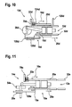
- FIG. 11 shows a portable power tool impact device 10e with a counterweight 20e of a mass vibration unit formed by a hammer tube 32e.
- An operation and an excitation of the counterweight 20e correspond to the example in FIG. 9 ,
- FIG. 12 shows a portable power tool impact device 10f with an excitation means 24f formed by a pneumatic means 30f.
- a counterweight 20f of a mass vibration unit in a housing 110f of the mass vibration unit.
- the housing 110f of the mass vibration unit has a cylindrical shape with two valves 132f, 134f.
- the counterweight 20f which is disk-shaped, is excited to counter vibrations of a hammer mechanism 12f, so that the counterweight 20f generates a counterforce 16f to a resultant force 18f of the hammer mechanism 12f.
- the counterweight 20f is supported on the housing 110f by means of a spring means 22f thereon.
- the two valves 132f, 134f are disposed on opposite housing walls 136f, 138f of the housing 110f, one of the two valves 132f for supplying air and the other of the two valves 134f for discharging air.
- the valve 132f for supplying Air is connected to a pneumatic element 46f of the impact mechanism assembly 12f via an air line 140f. Air is conducted via the air line 140f or the valve 132f by means of an overpressure in the pneumatic element 46f of the striking mechanism arrangement 12f into the housing 110f of the mass vibration unit and an overpressure is generated in the mass vibration unit.
- the positive air pressure in the housing 110f of the mass vibration unit pushes the counterweight 20f counter to a drive direction 26f of the hammer mechanism 12f against a spring force of the spring means 22f against the housing 110f, so as to produce a counter force 16f generated to the hammer mechanism 12f.
- the valve 134f for discharging air from the counterweight 20f is uncovered within a portion 142f of the housing 110f with the overpressure , air can be discharged into the hand tool.
Abstract
Description
Die Erfindung geht aus von einer Handwerkzeugmaschinenschlagwerkvorrichtung nach dem Oberbegriff des Anspruchs 1.The invention relates to a handheld power tool impact device according to the preamble of claim 1.
Aus der Patentanmeldung
Erfindungsgemäß eine Handwerkzeugmaschinenschlagwerkvorrichtung mit einer Schlagwerkanordnung gemäß Anspruch 1 vorgeschiagen, mit zumindest einer Einheit, die dazu vorgesehen ist, eine Gegenkraft zu einer aus der Schlagwerkanordnung resultierenden Kraft zu erzeugen, wobei die Einheit von einer Massenschwingungseinheit gebildet ist, wobei die Massenschwingungseinheit eine Gegenschwingungsmasse zur Schlagwerkanordnung aufweist, wobei die Einheit eine Arretiereinheit aufweist, die zu einer Sicherung der Gegenschwingungsmasse in einer Leerlaufposition vorgesehen ist, wobei die Arretiereinheit zumindest ein Arretierelement und ein Fixierelement aufweist und wobei zur Sicherung der Gegenschwingungsmasse in axialer Richtung das Arretierelement in eine Arretierausnehmung, die innerhalb der Gegenschwingungsmasse angeordnet ist, bewegbar ist, wobei das Fixierelement innerhalb des Arretierelements bewegbar angeordnet ist. Hierdurch kann eine vorteilhafte Reduzierung von Schwingungen an einem Gehäuse einer Handwerkzeugmaschine mit einer Handwerkzeugmaschinenschlagwerkvorrichtung, die durch die Generierung eines Schlagimpulses der Schlagwerkanordnung hervorgerufen werden, erreicht werden. Die erzeugte Gegenkraft und die aus der Schlagwerkanordnung resultierende Kraft sind vorzugsweise in entgegengesetzte Richtungen ausgerichtet, so dass eine vorteilhafte und zumindest teilweise Aufhebung der Kräfte bei einer Schwingungsreduzierung erzielt werden kann und somit besonders vorteilhaft eine nahezu vibrationsfreie Führung für einen Bediener der Handwerkzeugmaschine erreicht werden kann. Zweckmäßigerweise ist die Einheit dazu vorgesehen, die Gegenkraft innerhalb eines großen Drehzahlbereichs einer Antriebseinheit bzw. über einen hohen Schlagfrequenzbereich der Schlagwerkanordnung zu erzeugen, so dass die erzeugte Gegenkraft dabei in Richtung und Zeit auf eine Kompressionskraft der Schlagwerkanordnung vorteilhaft abgestimmt und eine maximale Schwingungsreduzierung erreicht werden kann. Die Einheit kann als eine mechanische, eine elektrische und/oder eine magnetische und/oder eine pneumatische Einheit und/oder als weitere, dem Fachmann als sinnvoll erscheinende Einheit ausgebildet sein und dabei eine mechanische, eine elektrische und/oder eine magnetische usw. Gegenkraft zur resultierenden Kraft der Schlagwerkanordnung erzeugen.According to the invention, a handheld power tool percussion device with a striking mechanism arrangement according to claim 1 is proposed, with at least one unit which is intended to generate a counterforce to a force resulting from the percussion mechanism, the unit being formed by a mass vibration unit is, wherein the mass vibration unit comprises a counterweight mass for striking mechanism arrangement, wherein the unit has a locking unit which is provided for securing the counterweight in an idle position, wherein the locking unit has at least one locking element and a fixing element and wherein for securing the counterweight in the axial direction of the Arresting element in a locking recess, which is arranged within the counter-vibration mass, is movable, wherein the fixing element is arranged movable within the locking element. In this way, an advantageous reduction of vibrations on a housing of a hand tool machine with a hand tool machine impact device, which are caused by the generation of a shock pulse of the impact mechanism, can be achieved. The generated counterforce and the force resulting from the hammer mechanism are preferably aligned in opposite directions, so that an advantageous and at least partial cancellation of the forces can be achieved in a vibration reduction and thus particularly advantageous a virtually vibration-free guidance for an operator of the power tool can be achieved. Conveniently, the unit is intended to generate the counterforce within a large speed range of a drive unit or a high impact frequency range of Schlagwerkanordnung so that the counterforce generated in the direction and time can be advantageously matched to a compression force of Schlagwerkanordnung and a maximum vibration reduction can be achieved , The unit may be designed as a mechanical, an electrical and / or a magnetic and / or a pneumatic unit and / or as further, the expert appears reasonable unit and thereby a mechanical, electrical and / or magnetic, etc. counterforce to generate resultant force of the percussion arrangement.
Erfindungsgemäß wird nach vorgeschlagen, dass die Einheit von einer Massenschwingungseinheit gebildet ist, wodurch konstruktiv einfach mittels einer mechanischen Anregung, insbesondere wenn die von der Massenschwingungseinheit gebildete Einheit eine Gegenschwingungsmasse aufweist, eine durch eine Gegenschwingung erzeugte Gegenkraft zur Kompressionskraft der Schlagwerkanordnung erzielt werden kann.According to the invention it is proposed that the unit is formed by a mass vibration unit, which structurally simple means of a mechanical excitation, especially if the unit formed by the mass vibration unit has a counterweight, a counterforce generated by a counter-vibration to the compression force of the hammer mechanism can be achieved.
Es wird optional vorgeschlagen, dass die Einheit zumindest ein Federmittel aufweist, das die Gegenschwingungsmasse abstützt, wodurch nach einer Anregung der Gegenschwingungsmasse eine vorteilhafte Rückführung der Gegenschwingungsmasse in die Ruheposition bzw. Ausgangsposition erreicht werden kann und somit eine erneute und insbesondere periodische Anregung der Gegenschwingungsmasse erreicht werden kann. Zudem wirkt durch das Federmittel bzw. durch eine Federkraft des Federmittels eine zusätzliche Kraft auf die Gegenschwingungsmasse entgegen einer Beschleunigungsrichtung der Gegenschwingungsmasse, so dass die Gegenkraft der Einheit vorteilhaft erhöht werden kann. Vorzugsweise stützt das Federmittel die Gegenschwingungsmasse an einem Gehäuse der Handwerkzeugmaschine ab.It is optionally proposed that the unit has at least one spring means which supports the counterweight mass, whereby, after an excitation of the counterweight mass, an advantageous return of the counterweight mass to the rest position or starting position can be achieved and thus a renewed and in particular periodic excitation of the counterweight mass can be achieved. In addition, acts by the spring means or by a spring force of the spring means an additional force on the countervailing mass against an acceleration direction of the countervailing mass, so that the counterforce of the unit can be advantageously increased. Preferably, the spring means supports the mating mass on a housing of the power tool.
Optional wird vorgeschlagen, dass die Einheit zumindest ein Anregungsmittel aufweist, welches mittels eines Antriebsmittels der Schlagwerkanordnung antreibbar ist, wodurch eine konstruktiv einfache Anpassung bzw. eine Kopplung der erzeugten Gegenschwingung bzw. der erzeugten Gegenkraft an eine Drehzahl der Antriebseinheit bzw. an eine Schlagfrequenz der Schlagwerkanordnung erreicht werden kann. Das Anregungsmittel kann dabei von einem elektrischen, einem magnetischen und/oder einem mechanischen Anregungsmittel und/oder weiteren, dem Fachmann als sinnvoll erscheinenden Anregungsmitteln gebildet sein.Optionally, it is proposed that the unit has at least one excitation means which can be driven by means of a drive means of the hammer mechanism, whereby a structurally simple adaptation or coupling of the generated counter-vibration or the generated counterforce to a rotational speed of the drive unit or to a beat frequency of the striking mechanism arrangement can be achieved. In this case, the excitation means can be formed by an electrical, a magnetic and / or a mechanical excitation means and / or further excitation means which appear expedient to the person skilled in the art.
Optional wird vorgeschlagen, dass die Gegenschwingungsmasse mittels des Anregungsmittels entgegen einer Antriebsrichtung der Schlagwerkanordnung anregbar ist, wodurch eine vorteilhafte Aufhebung der Gegenkraft und der resultierenden Kraft der Schlagwerkanordnung erreicht werden kann.Optionally, it is proposed that the countervibration mass can be excited by means of the excitation means counter to a drive direction of the striking mechanism arrangement, whereby an advantageous cancellation of the counterforce and the resulting force of the striking mechanism arrangement can be achieved.
Optional wird vorgeschlagen, dass das Anregungsmittel von einem Exzenterrad gebildet ist, so dass insbesondere eine periodische Anregung der Gegenschwingungsmasse erreicht werden kann, wobei das Exzenterrad vorzugsweise an eine Schlagfrequenz der Schlagwerkanordnung bzw. eine Drehzahl der Antriebseinheit gekoppelt ist.Optionally, it is proposed that the excitation means is formed by an eccentric wheel, so that in particular a periodic excitation of the countervibration mass is achieved can, wherein the eccentric wheel is preferably coupled to a beat frequency of the striking mechanism arrangement or a rotational speed of the drive unit.
Erfindungsgemäß wird vorgeschlagen, dass die Einheit eine Arretiereinheit aufweist, die zu einer Sicherung der Gegenschwingungsmasse in einer Leerlaufposition vorgesehen ist. Hierdurch kann eine unerwünschte Erzeugung von großen Gegenkräften bei einem Stillstand bzw. einem Verweilen eines Schlägers der Schlagwerkanordnung in einer Ruheposition vorteilhaft vermieden werden. Zudem kann somit ein unerwünschter Verschleiß der Handwerkzeugmaschinenschlagwerkvorrichtung vorteilhaft vermieden werden, und eine hohe Lebensdauer einzelner Bauteile bzw. Einheiten der Handwerkzeugmaschinenschlagwerkvorrichtung kann erzielt werden.According to the invention, it is proposed that the unit has a locking unit which is provided for securing the counterweight mass in an idling position. In this way, an undesired generation of large opposing forces during a standstill or a stay of a racket of Schlagwerkanordnung in a rest position can be advantageously avoided. In addition, undesired wear of the handheld power tool striking device can thus advantageously be avoided, and a high service life of individual components or units of the handheld power tool striking device can be achieved.
Es wird zudem eine Handwerkzeugmaschine mit einer Handwerkzeugmaschinenschlagwerkvorrichtung vorgeschlagen, und somit wird ein vorteilhafter Bedienkomfort mit einer geringen und/oder besonders vorteilhaft mit einer nahezu verschwindenden resultierenden Schwingung des Handwerkzeugmaschinengehäuses für einen Bediener der Handwerkzeugmaschine erreicht.In addition, a handheld power tool with a handheld power tool striking device is proposed, and thus an advantageous ease of operation with a low and / or particularly advantageous with a virtually vanishing resulting vibration of the power tool housing for an operator of the power tool is achieved.
Weitere Vorteile ergeben sich aus der folgenden Zeichnungsbeschreibung. In den
Bei den
Es zeigen:
- Fig. 1
- eine Handwerkzeugmaschine mit einer Handwerkzeugmaschinenschlagwerk- vorrichtung in einer schematischen Seitendar- stellung,
- Fig. 2
- die Handwerkzeugmaschinen- schlagwerkvorrichtung in einer schematischen Seitendarstellung,
- Fig. 3
- ein Exzenterrad der Handwerkzeugmaschinen- schlagwerkvorrichtung,
- Fig. 4
- eine zu
Figur 2 alternative Handwerkzeugma- schinenschlagwerkvorrichtung in einer schema- tischen Ansicht von oben, - Fig. 5
- die Handwerkzeugmaschinenschlagwerkvorrichtung aus
Figur 2 mit einem Anschlagmittel in einer schematischen Ansicht von oben, - Fig. 6
- die Handwerkzeugmaschinenschlagwerkvorrichtung aus
Figur 2 mit einem weiteren Federmittel in einer schematischen Ansicht von oben, - Fig. 7
- die erfindungsgemäße Handwerkzeugmaschinen- schlagwerkvorrichtung mit einer Arretierein- heit in einer schematischen Seitenansicht,
- Fig. 8
- die Handwerkzeugmaschinenschlagwerkvorrichtung aus
Figur 7 mit einer direkten Anordnung der Arretiereinheit an einem Hammerrohr in einer schematischen Seitenansicht, - Fig. 9
- eine weitere alternative Handwerkzeugmaschi- nenschlagwerkvorrichtung in einer schemati- schen Seitenansicht,
- Fig. 10
- die Handwerkzeugmaschinenschlagwerkvorrichtung aus
Figur 9 mit einer alternativen Anregung in einer schematischen Ansicht von oben, - Fig. 11
- eine weitere alternative Handwerkzeugmaschi- nenschlagwerkvorrichtung mit einer von einem Hammerrohr gebildeten Gegenschwingungsmasse in einer schematischen Seitenansicht und
- Fig. 12
- eine weitere alternative Handwerkzeugmaschi- nenschlagwerkvorrichtung mit einem Pneumatik- mittel als Anregungsmittel in einer schemati- schen Seitenansicht.
- Fig. 1
- a handheld power tool with a handheld power tool impactor in a schematic side view,
- Fig. 2
- the hand tool machine impact device in a schematic side view,
- Fig. 3
- an eccentric wheel of the portable power tool machine,
- Fig. 4
- one too
FIG. 2 alternative portable power tool impact device in a schematic view from above, - Fig. 5
- the hand tool machine strike device
FIG. 2 with a stop means in a schematic view from above, - Fig. 6
- the hand tool machine strike device
FIG. 2 with another spring means in a schematic view from above, - Fig. 7
- the hand-held power tool impacting device according to the invention with a locking unit in a schematic side view,
- Fig. 8
- the hand tool machine strike device
FIG. 7 with a direct arrangement of the locking unit on a hammer tube in a schematic side view, - Fig. 9
- FIG. 2 is a schematic side view of another alternative hand-held power tool impact device;
- Fig. 10
- the hand tool machine strike device
FIG. 9 with an alternative excitation in a schematic view from above, - Fig. 11
- a further alternative hand tool machine impact device with a counterweight formed by a hammer tube in a schematic side view and
- Fig. 12
- a further alternative hand tool machine impact device with a pneumatic medium as an excitation means in a schematic side view.
In
Zu einem Antrieb der Schlagwerkanordnung 12a wird von einer hier nicht näher dargestellten und von einem Elektromotor gebildeten Antriebseinheit der Handwerkzeugmaschine 36a ein Antriebsmoment erzeugt. Die Antriebseinheit überträgt ein Antriebsmoment auf ein von einer Antriebswelle gebildetes Antriebsmittel 38a, das senkrecht zur Antriebsrichtung 26a der Schlagwerkanordnung 12a ausgerichtet ist (
Die Massenschwingungseinheit ist in einem Bereich der Handwerkzeugmaschine 36a angeordnet, der, von der Antriebswelle aus betrachtet, der Antriebsrichtung 26a der Schlagwerkanordnung 12a entgegengerichtet ist. Zudem weist die Massenschwingungseinheit eine Gegenschwingungsmasse 20a, ein Federmittel 22a und ein von einem Exzenterrad 28a gebildetes Anregungsmittel 24a auf. Das Exzenterrad 28a wird über die Antriebswelle der Antriebseinheit, die zum Antrieb der Schlagwerkanordnung 12a vorgesehen ist, angetrieben und ist mit diesem verdrehfest verbunden. Das Exzenterrad 28a weist eine nockenförmige, asymmetrische Form einer Haupterstreckungsfläche 64a auf, die, bezogen auf eine kreisförmige Form, in einer Mitte eine Ausnehmung 66a zur drehfesten Befestigung mit der Antriebswelle aufweist (
Mittels des nockenförmigen Exzenterrads 28a wird die Gegenschwingungsmasse 20a entgegen einer Antriebsrichtung 26a der Schlagwerkanordnung 12a bewegt. Die Gegenschwingungsmasse 20a wird dabei entgegen einer Federkraft eines Federmittels 22a bewegt, wobei das Federmittel 22a die Gegenschwingungsmasse 20a an einem Gehäuse 70a der Handwerkzeugmaschine 36a abstützt. Zu einem Zeitpunkt der in Antriebsrichtung 26a weisenden Endstellung des Exzenterstifts 56a der Exzenterantriebseinheit 52a wirkt eine maximale von einer Kompressionskraft gebildete Kraft 18a der Schlagwerkanordnung 12a entgegen der Antriebsrichtung 26a der Schlagwerkanordnung 12a. Durch eine Anregung der Gegenschwingungsmasse 20a mittels des nockenförmigen Exzenterrads 28a wird eine Gegenkraft 16a erzeugt, die ein Maximum, bedingt durch die Anordnung der Massenschwingungseinheit, nahezu zeitgleich zur maximalen resultierenden Kraft 18a der Schlagwerkanordnung 12a erreicht. Die Gegenkraft 16a der Massenschwingungseinheit ist dabei der resultierenden Kraft 18a der Schlagwerkanordnung 12a entgegengerichtet, so dass sich die resultierende Kraft 18a der Schlagwerkanordnung 12a und die Gegenkraft 16a im Bereich der Antriebswelle möglichst aufheben und resultierende Schwingungen der Handwerkzeugmaschine 36a zumindest reduziert und/oder vermieden werden (
Das Federmittel 22a der Massenschwingungseinheit bewirkt dabei eine automatische Rückführung der Gegenschwingungsmasse 20a in die Ausgangssituation, um die Gegenschwingungsmasse 20a nach einem periodischen Umlauf um die Drehachse der Antriebswelle des nockenförmigen Exzenterrads 28a erneut entgegen der Federkraft des Federmittels 22a und entgegen der Antriebsrichtung 26a der Schlagwerkanordnung 12a zu bewegen. Mittels des von der Antriebswelle angetriebenen nockenförmigen Exzenterrads 28a ist die Gegenkraft 16a der Massenschwingungseinheit an eine momentane Schlagfrequenz der Schlagwerkanordnung 12a bzw. an eine Richtung und Zeit der aus der Schlagwerkanordnung 12a resultierenden Kraft 18a angepasst. Zudem bewirkt das Federmittel 22a eine erhöhte Trägheit bei einem Beschleunigen der Gegenschwingungsmasse 20a und die Gegenkraft 16a wirkt somit über einen längeren Zeitraum entgegen der resultierenden Kraft 18a der Schlagwerkanordnung 12a.The spring means 22a of the mass vibration unit causes an automatic return of the
In den
Die
An der Gegenschwingungsmasse 20b ist ein weiteres Federmittel 80b an einer in eine Antriebsrichtung 26b weisenden Seite angeordnet. Das Federmittel 80b ermöglicht ein gedämpftes Koppeln des Exzenterstifts 74b an die Gegenschwingungsmasse 20b, wobei der Exzenterstift 74b eine Bewegungsrichtung in eine Drehrichtung 72b des Exzenterrads 28b bzw. einer Antriebswelle aufweist. Der Exzenterstift 74b koppelt dabei zu einem Zeitpunkt an das Federelement 80b, in welchem in der Schlagwerkanordnung 12b eine Kompressionskraft aufgebaut wird. Bei weiterem Umdrehen des Exzenterrads 28b nimmt eine Kompressionskraft bzw. eine resultierende Kraft 18b entgegen der Antriebsrichtung 26b in der Schlagwerkanordnung 12b zu und gleichzeitig wird auch die Gegenschwingungsmasse 20b entgegen der Antriebsrichtung 26b gedrückt und damit eine Gegenkraft 16b durch eine Beschleunigung der Gegenschwingungsmasse 20b erzeugt. Befindet sich der Exzenterstift 56b zum Antrieb der Schlagwerkanordnung 12b in einer der Schlagwerkanordnung 12b zugewandten Endstellung bzw. befindet sich der Exzenterstift 74b zur Anregung der Gegenschwingungsmasse 20b in einer der Gegenschwingungsmasse 20b zugewandten Endstellung, resultiert aus der Schlagwerkanordnung 12b eine maximale Kraft 18b entgegen der Antriebsrichtung 26b und aus der Massenschwingungseinheit resultiert eine maximale Gegenkraft 16b in Richtung der Antriebsrichtung 26b, wobei sich die Kraft 18b und die Gegenkraft 16b zumindest teilweise gegenseitig aufheben.On the
Im Unterschied zur Anordnung in
In
In den
Wird die Leerlaufposition der Schlagwerkanordnung 12c aufgehoben, so wird das Hammerrohr 32c zusammen mit dem Haltering 92c in eine normale Meißelbetriebsposition geschoben und das Fixierelement 90c wird in die sich verjüngende Ausnehmung 98c des Arretierelements 88c entgegen der Antriebsrichtung 26c gedrückt. Hierdurch wird das Arretierelement 88c entgegen der Federkraft des Federelements 86c aus der Arretierausnehmung 102c der Gegenschwingungsmasse 20c gedrückt und die Gegenschwingungsmasse 20c mittels des Federmittels 22c in eine Ausgangsposition für eine erneute Anregung durch das Exzenterrad 28c gebracht (
Die Arretiereinheit 34c in
In den
In
In
Claims (4)
- Percussion mechanism apparatus for a portable power tool, comprising a percussion mechanism arrangement (12) and at least one unit (14) which is provided for generating a counterforce (16) to a force (18) resulting from the percussion mechanism arrangement (12), wherein the unit (14) is formed by a mass oscillating unit, wherein the mass oscillating unit has a counter oscillating mass (20c) relative to the percussion mechanism arrangement (12), wherein the unit (14) has a locking unit (34c) which is provided for securing the counter oscillating mass (20c) in an idling position, wherein the locking unit (34c) has at least one locking element (88c) and a fixing element (90c), and wherein, to secure the counter oscillating mass (20c) in the axial direction (100c), the locking element (88c) can be moved into a locking recess (102c) which is arranged within the counter oscillating mass (20c), characterized in that the fixing element (90c) is arranged so as to be movable within the locking element (88c).
- Percussion mechanism apparatus for a portable power tool according to Claim 1, characterized in that the unit (14) has at least one spring means (22) which supports the counter oscillating mass (20), wherein the unit (14) has at least one excitation means (24) which can be driven by a drive means (38) of the percussion mechanism arrangement (12), and wherein the counter oscillating mass (20) can be excited by the excitation means (24) against a drive direction (26) of the percussion mechanism arrangement (12).
- Percussion mechanism apparatus for a portable power tool according to Claim 2, characterized in that the excitation means (24) is formed by an eccentric wheel (28a; 28b; 28c; 28d; 28e).
- Portable power tool having a percussion mechanism apparatus for a portable power tool according to one of the preceding claims.
Applications Claiming Priority (2)
| Application Number | Priority Date | Filing Date | Title |
|---|---|---|---|
| DE102006053105A DE102006053105A1 (en) | 2006-11-10 | 2006-11-10 | Hand tools percussion device |
| PCT/EP2007/059988 WO2008055743A1 (en) | 2006-11-10 | 2007-09-20 | Mass oscillating unit for hand-held machine tools with a striking device |
Publications (2)
| Publication Number | Publication Date |
|---|---|
| EP2089192A1 EP2089192A1 (en) | 2009-08-19 |
| EP2089192B1 true EP2089192B1 (en) | 2011-03-23 |
Family
ID=38829021
Family Applications (1)
| Application Number | Title | Priority Date | Filing Date |
|---|---|---|---|
| EP07803568A Not-in-force EP2089192B1 (en) | 2006-11-10 | 2007-09-20 | Mass oscillating unit for hand-held machine tools with a striking device |
Country Status (6)
| Country | Link |
|---|---|
| EP (1) | EP2089192B1 (en) |
| CN (1) | CN101535007B (en) |
| AT (1) | ATE502732T1 (en) |
| DE (2) | DE102006053105A1 (en) |
| RU (1) | RU2466856C2 (en) |
| WO (1) | WO2008055743A1 (en) |
Families Citing this family (10)
| Publication number | Priority date | Publication date | Assignee | Title |
|---|---|---|---|---|
| DE102008044219A1 (en) * | 2008-12-01 | 2010-06-02 | Robert Bosch Gmbh | Hand machine tool device |
| DE102009027423A1 (en) * | 2009-07-02 | 2011-01-05 | Robert Bosch Gmbh | Device for reducing and / or compensating vibrations, in particular for a handheld power tool and for use in handheld power tools |
| DE102009044941A1 (en) * | 2009-09-24 | 2011-03-31 | Robert Bosch Gmbh | Counteroscillator, which is providable to compensate for housing vibrations of a power tool in this |
| DE102009047106A1 (en) * | 2009-11-25 | 2011-05-26 | Robert Bosch Gmbh | Variation of the natural frequency of vibrating means in power tools |
| DE102010039787A1 (en) * | 2010-08-26 | 2012-03-01 | Robert Bosch Gmbh | Hand tool |
| DE102012221517A1 (en) * | 2012-11-26 | 2014-05-28 | Robert Bosch Gmbh | Hand machine tool apparatus of powered hand tool e.g. drilling and/or percussion hammer, has sensor unit that is provided for detection of characteristic variable at portion of compensation unit |
| CN109404514B (en) * | 2017-08-14 | 2021-06-11 | 苏州宝时得电动工具有限公司 | Supporting structure of eccentric wheel, transmission mechanism and electric tool |
| US10814468B2 (en) | 2017-10-20 | 2020-10-27 | Milwaukee Electric Tool Corporation | Percussion tool |
| CN214723936U (en) | 2018-01-26 | 2021-11-16 | 米沃奇电动工具公司 | Impact tool |
| EP3626398A1 (en) * | 2018-09-19 | 2020-03-25 | Hilti Aktiengesellschaft | Forcibly energised biharmonic damper |
Family Cites Families (6)
| Publication number | Priority date | Publication date | Assignee | Title |
|---|---|---|---|---|
| SU130449A1 (en) * | 1959-12-18 | 1960-11-30 | Е.В. Александров | Electric hammer |
| GB2129733A (en) * | 1982-10-27 | 1984-05-23 | Jean Walton | More-vibration-free concrete breakers and percussion drills |
| DE10021355B4 (en) * | 2000-05-02 | 2005-04-28 | Hilti Ag | Beating electric hand tool with vibration-decoupled assemblies |
| CN2600223Y (en) * | 2002-12-11 | 2004-01-21 | 林青田 | Damping device of reciprocating pneumatic tool |
| CN101898352B (en) * | 2003-03-21 | 2013-01-23 | 百得有限公司 | Vibration reduction apparatus for power tool and power tool incorporating such apparatus |
| JP4527468B2 (en) * | 2004-08-17 | 2010-08-18 | 株式会社マキタ | Electric tool |
-
2006
- 2006-11-10 DE DE102006053105A patent/DE102006053105A1/en not_active Withdrawn
-
2007
- 2007-09-20 CN CN200780041828XA patent/CN101535007B/en not_active Expired - Fee Related
- 2007-09-20 WO PCT/EP2007/059988 patent/WO2008055743A1/en active Application Filing
- 2007-09-20 DE DE502007006800T patent/DE502007006800D1/en active Active
- 2007-09-20 EP EP07803568A patent/EP2089192B1/en not_active Not-in-force
- 2007-09-20 RU RU2009121814/02A patent/RU2466856C2/en not_active IP Right Cessation
- 2007-09-20 AT AT07803568T patent/ATE502732T1/en active
Also Published As
| Publication number | Publication date |
|---|---|
| ATE502732T1 (en) | 2011-04-15 |
| CN101535007B (en) | 2011-10-05 |
| EP2089192A1 (en) | 2009-08-19 |
| RU2009121814A (en) | 2010-12-20 |
| DE502007006800D1 (en) | 2011-05-05 |
| WO2008055743A1 (en) | 2008-05-15 |
| RU2466856C2 (en) | 2012-11-20 |
| CN101535007A (en) | 2009-09-16 |
| DE102006053105A1 (en) | 2008-05-15 |
Similar Documents
| Publication | Publication Date | Title |
|---|---|---|
| EP2089192B1 (en) | Mass oscillating unit for hand-held machine tools with a striking device | |
| EP2265420B1 (en) | Hand-held power tool for impacting driven tool attachments | |
| EP2017038B1 (en) | Hand tool machine with pneumatic striking mechanism | |
| EP2379282B1 (en) | Hand tool having counter-oscillator | |
| EP2265419A1 (en) | Hand-held power tool for percussively driven tool attachments | |
| EP2176036B1 (en) | Hand-held power tool comprising a spring unit | |
| DE102007061716A1 (en) | Tumbling drive of a hand tool machine | |
| EP2797721B1 (en) | Hand tool device | |
| WO2009103362A1 (en) | Handheld machine tool | |
| EP3638457B1 (en) | Hand-held power tool | |
| EP2269781A2 (en) | Device for reduction and/or compensation of vibrations, in particular for a handheld machine tool and for use in handheld machine tools | |
| EP2191939B1 (en) | Device for hand machine tool | |
| EP1787761A1 (en) | Motor-driven hammer drill | |
| WO2007090478A1 (en) | Portable power tool, in particular a hammer drill and/or a rotary demolition hammer | |
| DE102006059336A1 (en) | Handheld electrical machine tool comprises an electrical drive motor with a stator having a magnet arrangement fixed in an oscillating manner in a housing to form the damping body of an oscillation damper | |
| WO2005044521A1 (en) | Percussion device for a hand machine tool | |
| EP2646198A1 (en) | Hammer percussion mechanism | |
| WO2011000609A1 (en) | Device for reducing and/or compensating vibrations, in particular for a hand machine tool, and for application in hand machine tools | |
| EP2027972B1 (en) | Hand tool with reciprocating drive | |
| DE10142569A1 (en) | Manual tool machine has beater w ith piston connected to drive unit and transmission element, with rotarily driven curved element and piston rod | |
| EP2047951B1 (en) | Manual machine tool with a crank drive | |
| DE202016105294U1 (en) | Vibration damping device for a portable power tool, in particular a drill and / or chisel hammer | |
| EP2140982A1 (en) | Rotary and/or demolition hammer | |
| DE102015210177A1 (en) | Impact device for a hand tool | |
| EP4324597A1 (en) | Drill hammer or chisel hammer with a vibration-reduced impact mechanism unit |
Legal Events
| Date | Code | Title | Description |
|---|---|---|---|
| PUAI | Public reference made under article 153(3) epc to a published international application that has entered the european phase |
Free format text: ORIGINAL CODE: 0009012 |
|
| 17P | Request for examination filed |
Effective date: 20090610 |
|
| AK | Designated contracting states |
Kind code of ref document: A1 Designated state(s): AT BE BG CH CY CZ DE DK EE ES FI FR GB GR HU IE IS IT LI LT LU LV MC MT NL PL PT RO SE SI SK TR |
|
| 17Q | First examination report despatched |
Effective date: 20090914 |
|
| DAX | Request for extension of the european patent (deleted) | ||
| GRAP | Despatch of communication of intention to grant a patent |
Free format text: ORIGINAL CODE: EPIDOSNIGR1 |
|
| GRAC | Information related to communication of intention to grant a patent modified |
Free format text: ORIGINAL CODE: EPIDOSCIGR1 |
|
| GRAS | Grant fee paid |
Free format text: ORIGINAL CODE: EPIDOSNIGR3 |
|
| GRAA | (expected) grant |
Free format text: ORIGINAL CODE: 0009210 |
|
| AK | Designated contracting states |
Kind code of ref document: B1 Designated state(s): AT BE BG CH CY CZ DE DK EE ES FI FR GB GR HU IE IS IT LI LT LU LV MC MT NL PL PT RO SE SI SK TR |
|
| REG | Reference to a national code |
Ref country code: GB Ref legal event code: FG4D Free format text: NOT ENGLISH |
|
| REG | Reference to a national code |
Ref country code: CH Ref legal event code: EP |
|
| REG | Reference to a national code |
Ref country code: IE Ref legal event code: FG4D |
|
| REF | Corresponds to: |
Ref document number: 502007006800 Country of ref document: DE Date of ref document: 20110505 Kind code of ref document: P |
|
| REG | Reference to a national code |
Ref country code: DE Ref legal event code: R096 Ref document number: 502007006800 Country of ref document: DE Effective date: 20110505 |
|
| REG | Reference to a national code |
Ref country code: NL Ref legal event code: VDEP Effective date: 20110323 |
|
| PG25 | Lapsed in a contracting state [announced via postgrant information from national office to epo] |
Ref country code: LT Free format text: LAPSE BECAUSE OF FAILURE TO SUBMIT A TRANSLATION OF THE DESCRIPTION OR TO PAY THE FEE WITHIN THE PRESCRIBED TIME-LIMIT Effective date: 20110323 Ref country code: GR Free format text: LAPSE BECAUSE OF FAILURE TO SUBMIT A TRANSLATION OF THE DESCRIPTION OR TO PAY THE FEE WITHIN THE PRESCRIBED TIME-LIMIT Effective date: 20110624 Ref country code: LV Free format text: LAPSE BECAUSE OF FAILURE TO SUBMIT A TRANSLATION OF THE DESCRIPTION OR TO PAY THE FEE WITHIN THE PRESCRIBED TIME-LIMIT Effective date: 20110323 Ref country code: SE Free format text: LAPSE BECAUSE OF FAILURE TO SUBMIT A TRANSLATION OF THE DESCRIPTION OR TO PAY THE FEE WITHIN THE PRESCRIBED TIME-LIMIT Effective date: 20110323 |
|
| LTIE | Lt: invalidation of european patent or patent extension |
Effective date: 20110323 |
|
| PG25 | Lapsed in a contracting state [announced via postgrant information from national office to epo] |
Ref country code: CY Free format text: LAPSE BECAUSE OF FAILURE TO SUBMIT A TRANSLATION OF THE DESCRIPTION OR TO PAY THE FEE WITHIN THE PRESCRIBED TIME-LIMIT Effective date: 20110323 Ref country code: FI Free format text: LAPSE BECAUSE OF FAILURE TO SUBMIT A TRANSLATION OF THE DESCRIPTION OR TO PAY THE FEE WITHIN THE PRESCRIBED TIME-LIMIT Effective date: 20110323 Ref country code: SI Free format text: LAPSE BECAUSE OF FAILURE TO SUBMIT A TRANSLATION OF THE DESCRIPTION OR TO PAY THE FEE WITHIN THE PRESCRIBED TIME-LIMIT Effective date: 20110323 Ref country code: BG Free format text: LAPSE BECAUSE OF FAILURE TO SUBMIT A TRANSLATION OF THE DESCRIPTION OR TO PAY THE FEE WITHIN THE PRESCRIBED TIME-LIMIT Effective date: 20110623 |
|
| REG | Reference to a national code |
Ref country code: IE Ref legal event code: FD4D |
|
| PG25 | Lapsed in a contracting state [announced via postgrant information from national office to epo] |
Ref country code: EE Free format text: LAPSE BECAUSE OF FAILURE TO SUBMIT A TRANSLATION OF THE DESCRIPTION OR TO PAY THE FEE WITHIN THE PRESCRIBED TIME-LIMIT Effective date: 20110323 Ref country code: PT Free format text: LAPSE BECAUSE OF FAILURE TO SUBMIT A TRANSLATION OF THE DESCRIPTION OR TO PAY THE FEE WITHIN THE PRESCRIBED TIME-LIMIT Effective date: 20110725 |
|
| PG25 | Lapsed in a contracting state [announced via postgrant information from national office to epo] |
Ref country code: IS Free format text: LAPSE BECAUSE OF FAILURE TO SUBMIT A TRANSLATION OF THE DESCRIPTION OR TO PAY THE FEE WITHIN THE PRESCRIBED TIME-LIMIT Effective date: 20110723 Ref country code: SK Free format text: LAPSE BECAUSE OF FAILURE TO SUBMIT A TRANSLATION OF THE DESCRIPTION OR TO PAY THE FEE WITHIN THE PRESCRIBED TIME-LIMIT Effective date: 20110323 Ref country code: RO Free format text: LAPSE BECAUSE OF FAILURE TO SUBMIT A TRANSLATION OF THE DESCRIPTION OR TO PAY THE FEE WITHIN THE PRESCRIBED TIME-LIMIT Effective date: 20110323 Ref country code: ES Free format text: LAPSE BECAUSE OF FAILURE TO SUBMIT A TRANSLATION OF THE DESCRIPTION OR TO PAY THE FEE WITHIN THE PRESCRIBED TIME-LIMIT Effective date: 20110704 Ref country code: CZ Free format text: LAPSE BECAUSE OF FAILURE TO SUBMIT A TRANSLATION OF THE DESCRIPTION OR TO PAY THE FEE WITHIN THE PRESCRIBED TIME-LIMIT Effective date: 20110323 |
|
| PG25 | Lapsed in a contracting state [announced via postgrant information from national office to epo] |
Ref country code: NL Free format text: LAPSE BECAUSE OF FAILURE TO SUBMIT A TRANSLATION OF THE DESCRIPTION OR TO PAY THE FEE WITHIN THE PRESCRIBED TIME-LIMIT Effective date: 20110323 |
|
| PLBE | No opposition filed within time limit |
Free format text: ORIGINAL CODE: 0009261 |
|
| STAA | Information on the status of an ep patent application or granted ep patent |
Free format text: STATUS: NO OPPOSITION FILED WITHIN TIME LIMIT |
|
| PG25 | Lapsed in a contracting state [announced via postgrant information from national office to epo] |
Ref country code: IE Free format text: LAPSE BECAUSE OF FAILURE TO SUBMIT A TRANSLATION OF THE DESCRIPTION OR TO PAY THE FEE WITHIN THE PRESCRIBED TIME-LIMIT Effective date: 20110323 |
|
| 26N | No opposition filed |
Effective date: 20111227 |
|
| PG25 | Lapsed in a contracting state [announced via postgrant information from national office to epo] |
Ref country code: PL Free format text: LAPSE BECAUSE OF FAILURE TO SUBMIT A TRANSLATION OF THE DESCRIPTION OR TO PAY THE FEE WITHIN THE PRESCRIBED TIME-LIMIT Effective date: 20110323 Ref country code: DK Free format text: LAPSE BECAUSE OF FAILURE TO SUBMIT A TRANSLATION OF THE DESCRIPTION OR TO PAY THE FEE WITHIN THE PRESCRIBED TIME-LIMIT Effective date: 20110323 |
|
| BERE | Be: lapsed |
Owner name: ROBERT BOSCH G.M.B.H. Effective date: 20110930 |
|
| REG | Reference to a national code |
Ref country code: DE Ref legal event code: R097 Ref document number: 502007006800 Country of ref document: DE Effective date: 20111227 |
|
| PG25 | Lapsed in a contracting state [announced via postgrant information from national office to epo] |
Ref country code: MC Free format text: LAPSE BECAUSE OF NON-PAYMENT OF DUE FEES Effective date: 20110930 |
|
| REG | Reference to a national code |
Ref country code: CH Ref legal event code: PL |
|
| PG25 | Lapsed in a contracting state [announced via postgrant information from national office to epo] |
Ref country code: IT Free format text: LAPSE BECAUSE OF FAILURE TO SUBMIT A TRANSLATION OF THE DESCRIPTION OR TO PAY THE FEE WITHIN THE PRESCRIBED TIME-LIMIT Effective date: 20110323 |
|
| PG25 | Lapsed in a contracting state [announced via postgrant information from national office to epo] |
Ref country code: BE Free format text: LAPSE BECAUSE OF NON-PAYMENT OF DUE FEES Effective date: 20110930 |
|
| PG25 | Lapsed in a contracting state [announced via postgrant information from national office to epo] |
Ref country code: CH Free format text: LAPSE BECAUSE OF NON-PAYMENT OF DUE FEES Effective date: 20110930 Ref country code: LI Free format text: LAPSE BECAUSE OF NON-PAYMENT OF DUE FEES Effective date: 20110930 |
|
| PG25 | Lapsed in a contracting state [announced via postgrant information from national office to epo] |
Ref country code: MT Free format text: LAPSE BECAUSE OF FAILURE TO SUBMIT A TRANSLATION OF THE DESCRIPTION OR TO PAY THE FEE WITHIN THE PRESCRIBED TIME-LIMIT Effective date: 20110323 |
|
| PG25 | Lapsed in a contracting state [announced via postgrant information from national office to epo] |
Ref country code: LU Free format text: LAPSE BECAUSE OF NON-PAYMENT OF DUE FEES Effective date: 20110920 |
|
| PG25 | Lapsed in a contracting state [announced via postgrant information from national office to epo] |
Ref country code: TR Free format text: LAPSE BECAUSE OF FAILURE TO SUBMIT A TRANSLATION OF THE DESCRIPTION OR TO PAY THE FEE WITHIN THE PRESCRIBED TIME-LIMIT Effective date: 20110323 |
|
| PG25 | Lapsed in a contracting state [announced via postgrant information from national office to epo] |
Ref country code: HU Free format text: LAPSE BECAUSE OF FAILURE TO SUBMIT A TRANSLATION OF THE DESCRIPTION OR TO PAY THE FEE WITHIN THE PRESCRIBED TIME-LIMIT Effective date: 20110323 |
|
| REG | Reference to a national code |
Ref country code: AT Ref legal event code: MM01 Ref document number: 502732 Country of ref document: AT Kind code of ref document: T Effective date: 20120920 |
|
| PG25 | Lapsed in a contracting state [announced via postgrant information from national office to epo] |
Ref country code: AT Free format text: LAPSE BECAUSE OF NON-PAYMENT OF DUE FEES Effective date: 20120920 |
|
| PGFP | Annual fee paid to national office [announced via postgrant information from national office to epo] |
Ref country code: FR Payment date: 20140917 Year of fee payment: 8 |
|
| REG | Reference to a national code |
Ref country code: FR Ref legal event code: ST Effective date: 20160531 |
|
| PG25 | Lapsed in a contracting state [announced via postgrant information from national office to epo] |
Ref country code: FR Free format text: LAPSE BECAUSE OF NON-PAYMENT OF DUE FEES Effective date: 20150930 |
|
| PGFP | Annual fee paid to national office [announced via postgrant information from national office to epo] |
Ref country code: GB Payment date: 20170925 Year of fee payment: 11 |
|
| PGFP | Annual fee paid to national office [announced via postgrant information from national office to epo] |
Ref country code: DE Payment date: 20171128 Year of fee payment: 11 |
|
| REG | Reference to a national code |
Ref country code: DE Ref legal event code: R119 Ref document number: 502007006800 Country of ref document: DE |
|
| GBPC | Gb: european patent ceased through non-payment of renewal fee |
Effective date: 20180920 |
|
| PG25 | Lapsed in a contracting state [announced via postgrant information from national office to epo] |
Ref country code: DE Free format text: LAPSE BECAUSE OF NON-PAYMENT OF DUE FEES Effective date: 20190402 |
|
| PG25 | Lapsed in a contracting state [announced via postgrant information from national office to epo] |
Ref country code: GB Free format text: LAPSE BECAUSE OF NON-PAYMENT OF DUE FEES Effective date: 20180920 |