JP4527468B2 - Electric tool - Google Patents
Electric tool Download PDFInfo
- Publication number
- JP4527468B2 JP4527468B2 JP2004237255A JP2004237255A JP4527468B2 JP 4527468 B2 JP4527468 B2 JP 4527468B2 JP 2004237255 A JP2004237255 A JP 2004237255A JP 2004237255 A JP2004237255 A JP 2004237255A JP 4527468 B2 JP4527468 B2 JP 4527468B2
- Authority
- JP
- Japan
- Prior art keywords
- gear
- rotation
- internal gear
- power transmission
- planetary gear
- Prior art date
- Legal status (The legal status is an assumption and is not a legal conclusion. Google has not performed a legal analysis and makes no representation as to the accuracy of the status listed.)
- Expired - Fee Related
Links
- 230000007246 mechanism Effects 0.000 claims description 86
- 230000005540 biological transmission Effects 0.000 claims description 83
- 230000033001 locomotion Effects 0.000 claims description 43
- 230000002093 peripheral effect Effects 0.000 claims description 6
- 238000003754 machining Methods 0.000 claims description 4
- 210000000078 claw Anatomy 0.000 description 17
- 238000010586 diagram Methods 0.000 description 6
- 238000006243 chemical reaction Methods 0.000 description 5
- 239000004519 grease Substances 0.000 description 4
- 238000000034 method Methods 0.000 description 3
- 230000001105 regulatory effect Effects 0.000 description 3
- 230000001629 suppression Effects 0.000 description 3
- 238000013016 damping Methods 0.000 description 2
- 230000003247 decreasing effect Effects 0.000 description 2
- 238000005516 engineering process Methods 0.000 description 2
- 238000010276 construction Methods 0.000 description 1
- 238000006073 displacement reaction Methods 0.000 description 1
- 230000009931 harmful effect Effects 0.000 description 1
- 239000010687 lubricating oil Substances 0.000 description 1
- 230000000149 penetrating effect Effects 0.000 description 1
- 230000006641 stabilisation Effects 0.000 description 1
- 238000011105 stabilization Methods 0.000 description 1
Images


Classifications
-
- B—PERFORMING OPERATIONS; TRANSPORTING
- B25—HAND TOOLS; PORTABLE POWER-DRIVEN TOOLS; MANIPULATORS
- B25D—PERCUSSIVE TOOLS
- B25D17/00—Details of, or accessories for, portable power-driven percussive tools
- B25D17/24—Damping the reaction force
-
- B—PERFORMING OPERATIONS; TRANSPORTING
- B25—HAND TOOLS; PORTABLE POWER-DRIVEN TOOLS; MANIPULATORS
- B25D—PERCUSSIVE TOOLS
- B25D11/00—Portable percussive tools with electromotor or other motor drive
- B25D11/005—Arrangements for adjusting the stroke of the impulse member or for stopping the impact action when the tool is lifted from the working surface
-
- B—PERFORMING OPERATIONS; TRANSPORTING
- B25—HAND TOOLS; PORTABLE POWER-DRIVEN TOOLS; MANIPULATORS
- B25D—PERCUSSIVE TOOLS
- B25D11/00—Portable percussive tools with electromotor or other motor drive
- B25D11/06—Means for driving the impulse member
- B25D11/12—Means for driving the impulse member comprising a crank mechanism
- B25D11/125—Means for driving the impulse member comprising a crank mechanism with a fluid cushion between the crank drive and the striking body
-
- B—PERFORMING OPERATIONS; TRANSPORTING
- B25—HAND TOOLS; PORTABLE POWER-DRIVEN TOOLS; MANIPULATORS
- B25D—PERCUSSIVE TOOLS
- B25D2211/00—Details of portable percussive tools with electromotor or other motor drive
- B25D2211/003—Crossed drill and motor spindles
-
- B—PERFORMING OPERATIONS; TRANSPORTING
- B25—HAND TOOLS; PORTABLE POWER-DRIVEN TOOLS; MANIPULATORS
- B25D—PERCUSSIVE TOOLS
- B25D2216/00—Details of portable percussive machines with superimposed rotation, the rotational movement of the output shaft of a motor being modified to generate axial impacts on the tool bit
- B25D2216/0007—Details of percussion or rotation modes
- B25D2216/0046—Preventing rotation
-
- B—PERFORMING OPERATIONS; TRANSPORTING
- B25—HAND TOOLS; PORTABLE POWER-DRIVEN TOOLS; MANIPULATORS
- B25D—PERCUSSIVE TOOLS
- B25D2217/00—Details of, or accessories for, portable power-driven percussive tools
- B25D2217/0073—Arrangements for damping of the reaction force
- B25D2217/0076—Arrangements for damping of the reaction force by use of counterweights
- B25D2217/0088—Arrangements for damping of the reaction force by use of counterweights being mechanically-driven
-
- B—PERFORMING OPERATIONS; TRANSPORTING
- B25—HAND TOOLS; PORTABLE POWER-DRIVEN TOOLS; MANIPULATORS
- B25D—PERCUSSIVE TOOLS
- B25D2250/00—General details of portable percussive tools; Components used in portable percussive tools
- B25D2250/005—Adjustable tool components; Adjustable parameters
- B25D2250/021—Stroke length
Landscapes
- Engineering & Computer Science (AREA)
- Mechanical Engineering (AREA)
- Percussive Tools And Related Accessories (AREA)
Description
本発明は、駆動モータの回転出力を工具ビットの長軸方向への直線運動に変換する動力伝達機構を有する電動往復動式工具の構成技術に関する。 The present invention relates to a construction technique of an electric reciprocating tool having a power transmission mechanism that converts a rotational output of a drive motor into a linear motion of a tool bit in a major axis direction.
特公平4−31801号公報(特許文献1)では、いわゆる始動クラッチが設定された電動ハンマの構成が開示されている。この電動ハンマでは、ハンマビットを保持するスピンドル内に軸方向に摺動自在に設けられたストライカとプッシャを介してクラッチの入切が制御される。これにより、駆動モータを作動させても、ハンマビットが被加工材に押圧されていない状態では打撃手段が往復運動を行なうことがなく、被加工材にハンマビットを押圧することで初めて打撃手段の動作が開始されるように構成される。 Japanese Patent Publication No. 4-31801 (Patent Document 1) discloses a configuration of an electric hammer in which a so-called start clutch is set. In this electric hammer, on / off of the clutch is controlled via a striker and a pusher that are slidable in the axial direction in a spindle that holds the hammer bit. Thereby, even if the drive motor is operated, the hitting means does not reciprocate in a state where the hammer bit is not pressed against the workpiece, and the hitting means of the hitting means is not pressed until the hammer bit is pressed against the workpiece. The operation is configured to be started.
上記開示技術によれば、加工作業開始の際の始動特性を向上した始動クラッチとの協働によってハンマビットの駆動が制御されるが、かかる駆動機構の始動特性の向上に留まらず、ハンマビットに作用する負荷に応じた駆動機構の作動態様について一層合理的な機構を探求する要請が高い。
本発明は、かかる点に鑑みてなされたものであり、電動往復動式工具において、駆動モータの回転出力を工具ビットの長軸方向への直線運動に変換する動力伝達機構の一層の合理化に資する技術を提供することを目的とする。 The present invention has been made in view of the above points, and contributes to further rationalization of a power transmission mechanism that converts a rotational output of a drive motor into a linear motion in the long axis direction of a tool bit in an electric reciprocating tool. The purpose is to provide technology.
上記課題を達成するため、各請求項記載の発明が構成される。
請求項1に記載の発明によれば、工具ビット、駆動モータおよび動力伝達機構を有する電動往復動式工具が構成される。電動往復動式工具としては、ハンマ、ハンマドリル、ジグソー、レシプロソー等といったように、工具ビットが、直線運動することで被加工材に加工作業を行う態様の作業工具を広く包含するものとする。駆動モータは、かかる工具ビットを駆動する。動力伝達機構は、駆動モータの回転出力を前記工具ビット長軸方向への直線運動に変換する手段であり、インターナルギア、遊星歯車、および動力伝達部を有する。このうちインターナルギアは、回転自在に支持されるとともに、常時には回転規制機構によって回転が規制される構成とされる。また遊星歯車は、インターナルギアの中心回りに周回する構成とされる。動力伝達部は、遊星歯車に偏心状に設けられる。本発明における動力伝達機構では、駆動モータの回転出力によって遊星歯車をインターナルギアの中心回りに公転状に周回させることで、遊星歯車に設けられた動力伝達部を当該遊星歯車とともにインターナルギアの中心回りに周回動作させる。そして動力伝達部の周回動作のうち、上記工具ビット長軸方向への直線運動成分を利用して駆動モータの動力伝達が図られるよう構成されるものである。
In order to achieve the above object, the invention described in each claim is configured.
According to invention of
本発明に係る動力伝達機構では、動力伝達部は、遊星歯車に偏心状に設けられている。そして工具ビットに作用する負荷に基づいて回転規制機構によるインターナルギアの回転規制を解除して当該インターナルギアの所定方向への所定量の回転を許容することにより、インターナルギアと遊星歯車の近接部位に対する動力伝達部の位置を相対的に変化させることが可能とされる。換言すれば、インターナルギアに対し遊星歯車が公転するときの動力伝達部の軌道を工具ビットに対して相対的に変化させることが可能とされる。なお「所定方向」とは、インターナルギアの回転規制が解除されることに基づき当該インターナルギアが回転される方向であり、動力伝達機構を通じて当該インターナルギアを駆動する駆動モータの回転方向によって定められる。すなわち本発明では、所定方向に回転動作する駆動モータにより、動力伝達機構を経由してインターナルギアに当該駆動モータの回転力が作用するとともに、その回転力によるインターナルギアの自由な回転を規制する構成を採用する関係で、上記「所定方向」は、駆動モータの回転方向に基づいて特定される。更に言えば、駆動モータによって動力伝達機構が駆動されるときに当該インターナルギアに作用する回転力の方向によって特定される。また「工具ビットに作用する負荷に基づいてインターナルギアの所定量の回転を許容」とは、工具ビットに作用する負荷量が変化した場合にインターナルギアの回転を許容する態様を広く包含し、工具ビットの周方向に作用する負荷、工具ビットの軸方向に作用する負荷など、工具ビットの各種方向へ作用する負荷を包含するものとする。例えば加工作業の際に作業者による被加工材への工具の押圧が解除された場合に、インターナルギアの回転を許容するといった態様が採用可能である。また「インターナルギアと遊星歯車の近接部位」とは、インターナルギアと遊星歯車が最も近接している部位をいう。更に「動力伝達部の位置を相対的に変化」とは、インターナルギアと遊星歯車の近接部位に対する動力伝達部の位置が変化する態様を広く包含するものとする。 In the power transmission mechanism according to the present invention, the power transmission unit is provided eccentrically on the planetary gear. Based on the load acting on the tool bit, the rotation restriction of the internal gear by the rotation restriction mechanism is canceled and the internal gear is allowed to rotate in a predetermined direction by a predetermined amount. It is possible to relatively change the position of the power transmission unit. In other words, the trajectory of the power transmission portion when the planetary gear revolves with respect to the internal gear can be changed relative to the tool bit. The “predetermined direction” is a direction in which the internal gear is rotated based on the release of the internal gear rotation restriction, and is determined by the rotation direction of the drive motor that drives the internal gear through the power transmission mechanism. That is, in the present invention, the drive motor that rotates in a predetermined direction causes the rotational force of the drive motor to act on the internal gear via the power transmission mechanism, and restricts the free rotation of the internal gear by the rotational force. The “predetermined direction” is specified based on the rotation direction of the drive motor. More specifically, it is specified by the direction of the rotational force acting on the internal gear when the power transmission mechanism is driven by the drive motor. Further, “allowing a predetermined amount of rotation of the internal gear based on the load acting on the tool bit” widely includes a mode in which the rotation of the internal gear is permitted when the load amount acting on the tool bit changes. Loads acting in various directions of the tool bit, such as loads acting in the circumferential direction of the bit and loads acting in the axial direction of the tool bit, are included. For example, it is possible to adopt a mode in which the rotation of the internal gear is allowed when the pressing of the tool against the workpiece by the worker is released during the machining operation. The “proximal part of the internal gear and the planetary gear” means a part where the internal gear and the planetary gear are closest to each other. Further, “relatively changing the position of the power transmission unit” broadly encompasses an aspect in which the position of the power transmission unit with respect to the proximity of the internal gear and the planetary gear changes.
回転規制機構によるインターナルギアの回転規制を解除して当該インターナルギアの所定方向への所定量の回転を許容することにより(換言すれば、インターナルギアの回転規制位置を変更することにより)、例えば、インターナルギアと遊星歯車の近接部位が、工具ビットの長軸方向の前側端部領域ないし後側端部領域に位置している場合に、動力伝達部が当該近接部位近傍に配置されるように構成すれば、遊星歯車がインターナルギアの中心回りに周回することで、動力伝達部は、上記前側端部領域と後側端部領域との間で工具ビット長軸方向への直線運動成分を有しつつ周回動作することが可能となる。換言すれば、かかる構成により動力伝達部の工具ビット長軸方向への直線運動成分を大きく確保することが可能となる。なお上記の場合において、動力伝達部の工具ビット長軸方向への運動の周期性を確保するには、遊星歯車がインターナルギア中心回りに1回公転動作する毎に、遊星歯車が当該遊星歯車中心回りに2回自転するように設定する必要がある。また遊星歯車の自転方向は、公転方向に対して逆にするのが好ましい。 By releasing the rotation restriction of the internal gear by the rotation restriction mechanism and allowing the rotation of the internal gear in a predetermined direction (in other words, by changing the rotation restriction position of the internal gear), for example, When the proximity part of the internal gear and the planetary gear is located in the front end region or the rear end region in the long axis direction of the tool bit, the power transmission part is arranged near the proximity part Then, the planetary gear circulates around the center of the internal gear, so that the power transmission portion has a linear motion component in the tool bit long axis direction between the front end region and the rear end region. It is possible to operate while rotating. In other words, this configuration makes it possible to ensure a large linear motion component in the tool bit long axis direction of the power transmission unit. In the above case, in order to ensure the periodicity of the movement of the power transmission portion in the tool bit major axis direction, the planetary gear is centered on the planetary gear each time the planetary gear revolves once around the internal gear center. It is necessary to set it to rotate twice around. The rotation direction of the planetary gear is preferably reversed with respect to the revolution direction.
また、回転規制機構によるインターナルギアの回転規制を解除して当該インターナルギアの所定量の回転を許容することにより(換言すれば、インターナルギアの回転規制位置を変更することにより)、例えば、インターナルギアと遊星歯車の近接部位が、工具ビットの長軸方向の前側端部領域ないし後側端部領域に位置している場合に、動力伝達部が遊星歯車のうち当該近接部位と対向する側の周縁領域に配置されるように構成すれば、遊星歯車がインターナルギアの中心回りに周回することで、動力伝達部は、上記近接部位と対向する側の領域において工具ビット長軸方向に直線運動成分を有しつつ周回動作することが可能となる。かかる構成により動力伝達部の工具ビット長軸方向への運動成分を小さくすることが可能となる。なおこの場合において、遊星歯車の中心と当該遊星歯車上の動力伝達部との距離をa、遊星歯車の中心とインターナルギアの中心(遊星ギアの公転の中心)との距離をbとし、a=bに設定すれば、上記近接部位と対向する側に配置された動力伝達部は、遊星歯車の周回動作にもかかわらず、工具ビット長軸方向への直線運動成分がゼロとなり、動力伝達部の工具ビット長軸方向への直線運動成分をゼロに設定することが可能となる。 Further, by releasing the rotation restriction of the internal gear by the rotation restriction mechanism and allowing the rotation of the internal gear by a predetermined amount (in other words, by changing the rotation restriction position of the internal gear), for example, the internal gear And the planetary gear adjacent portion is located in the front end region or the rear end region in the long axis direction of the tool bit, the periphery of the planetary gear on the side facing the adjacent portion in the planetary gear If it is configured to be arranged in the region, the planetary gear circulates around the center of the internal gear, so that the power transmission unit generates a linear motion component in the tool bit long axis direction in the region on the side facing the adjacent portion. It is possible to operate around while holding. With this configuration, it is possible to reduce the motion component of the power transmission unit in the tool bit long axis direction. In this case, the distance between the center of the planetary gear and the power transmission portion on the planetary gear is a, the distance between the center of the planetary gear and the center of the internal gear (the center of revolution of the planetary gear) is b, and a = If it is set to b, the power transmission unit arranged on the side facing the adjacent part has zero linear motion component in the tool bit major axis direction despite the circular operation of the planetary gear, and the power transmission unit The linear motion component in the tool bit long axis direction can be set to zero.
このように遊星歯車に動力伝達部を偏心状に設け、インターナルギアの回転を許容することによってインターナルギアと遊星歯車の近接部位に対する動力伝達部の相対的な位置の変化を利用することで、動力伝達部の工具ビット長軸方向への運動量を変化させることが可能とされる。また上述のように「運動量を変化」させる態様として、運動量が増減する態様はもちろん、運動量がゼロとなる態様も好適に包含するものとする。 In this way, the planetary gear is provided with a power transmission portion eccentrically, and by allowing the internal gear to rotate, by utilizing the change in the relative position of the power transmission portion with respect to the vicinity of the internal gear and the planetary gear, It is possible to change the momentum of the transmission portion in the tool bit long axis direction. In addition, as described above, as a mode of “changing the amount of exercise”, a mode in which the amount of exercise is zero as well as a mode of increasing or decreasing the amount of exercise is suitably included.
本発明によれば、工具ビットに作用する負荷に基づいて動力伝達部の位置を相対的に変化させて当該動力伝達部の工具ビット長軸方向への運動量を可変とする構成を採用する。このため、かかる動力伝達部の運動量を利用した各種の駆動機構、例えば工具ビットの駆動機構、あるいは工具ビットを駆動する際の制振を行うカウンタウェイトの駆動機構において、工具ビットやカウンタウェイトといった駆動対象物の駆動量を適宜に変化させることが可能となる。特に、駆動対象物の駆動量は工具ビットに作用する負荷に基づいて可変とすることができるため、例えば工具ビットによる被加工材への加工作業の有無、すなわち工具ビットによる有負荷駆動・無負荷駆動といった作業状態に応じて駆動対象物の駆動量を変化させることが可能となり、電動往復動式工具における合理的な駆動制御を行うことが可能となる。 According to this invention, the structure which changes the position of a power transmission part relatively based on the load which acts on a tool bit, and makes the momentum of the tool bit long-axis direction of the said power transmission part variable is employ | adopted. For this reason, in various drive mechanisms using the momentum of the power transmission unit, such as a tool bit drive mechanism, or a counter weight drive mechanism that controls vibration when driving the tool bit, drive such as a tool bit or a counter weight. It becomes possible to appropriately change the driving amount of the object. In particular, the drive amount of the object to be driven can be made variable based on the load acting on the tool bit. For example, whether or not there is a machining operation on the workpiece by the tool bit, that is, loaded or unloaded by the tool bit. It becomes possible to change the driving amount of the driven object in accordance with the work state such as driving, and rational driving control in the electric reciprocating tool can be performed.
このように、工具ビットに作用する負荷に基づいて駆動対象物の駆動量を可変とする機構は、電動往復動式工具の様々な作業態様に適用することが可能である。例えば、工具ビットへの負荷が解除された場合に工具ビットの駆動量がゼロとなるように設定すれば、電動ハンマ等における始動クラッチとして利用することが可能となる。しかも、この場合には、駆動モータの回転出力を増減することなく、動力伝達部の相対位置を変更するだけで工具ビットの駆動制御を行なうことができるため、工具の始動特性を向上することが可能となる。 As described above, the mechanism that makes the drive amount of the driven object variable based on the load acting on the tool bit can be applied to various working modes of the electric reciprocating tool. For example, if the tool bit drive amount is set to zero when the load on the tool bit is released, the tool bit can be used as a starting clutch in an electric hammer or the like. In addition, in this case, since the drive control of the tool bit can be performed only by changing the relative position of the power transmission unit without increasing or decreasing the rotational output of the drive motor, the starting characteristics of the tool can be improved. It becomes possible.
本発明においては、インターナルギアにつき、前記回転規制機構による当該インターナルギアの回転の規制が解除された状態において前記所定方向への回転を許容し、かつこれとは反対側への回転を規制するための手段を備えている。すなわち、インターナルギアは、回転規制機構による回転の規制が解除された状態のときに、一方向にのみ、換言すれば、動力伝達部の工具ビット長軸方向への運動量を変化させる方向へのみ回転することが許容された構成とされ、典型的には、ワンウェイクラッチを用いることで好適に実現される。またインターナルギアの一方向のみの回転を許容する態様としては、インターナルギアを直接に一方向のみに回転できるようにする態様、あるいは当該インターナルギアの回転に基づいて回転する回転体を一方向のみに回転できるようにする態様のいずれも好適に包含する。工具ビットに作用する負荷に基づいて回転規制機構による回転規制作用が解除されてインターナルギアの所定量の回転が許容される際、換言すれば、インターナルギアの回転規制位置を変更する際、当該インターナルギアは、動力伝達部の工具ビット長軸方向への運動量を変化させる方向にのみ回転することが許容される。このことは、許容された方向の回転のみを規制することで、当該インターナルギアを回転規制位置にガタツキのない状態で固定することが可能になる。
例えば、インターナルギアを回転規制(固定)する場合において、当該インターナルギアが双方向に回転を許容される構成であれば、双方向につきそれぞれ回転を規制しない限り、いわゆるガタツキが生じてしまう。本発明によれば、上記のことから、回転規制機構によってインターナルギアを予め設定された位置に確実に固定することができ、固定状態の位置精度を向上することが可能となる。因みに、インターナルギアには、下記の如き回転力が作用している。1つは、駆動モータの回転出力によって駆動されて遊星歯車を回転自在に支持するキャリアとの接触に伴う摩擦あるいは潤滑油として封入されているグリース等を介して伝達される回転力であり、他の1つは、遊星歯車とキャリアとの摩擦に基づく遊星歯車の公転により作用する回転力であり、更に他の1つは、動力伝達部が駆動しようとしている物体からの反力による回転力である。
In the present invention, the internal gear is allowed to rotate in the predetermined direction in a state where the rotation restriction of the internal gear by the rotation restriction mechanism is released , and to restrict the rotation to the opposite side. It is equipped with the means. In other words, the internal gear rotates only in one direction when the rotation restriction by the rotation restriction mechanism is released, in other words, only in the direction in which the momentum of the power transmission portion in the tool bit long axis direction is changed. This configuration is permitted, and is typically realized by using a one-way clutch. Further, as a mode allowing rotation of the internal gear in only one direction, a mode in which the internal gear can be directly rotated in only one direction, or a rotating body that rotates based on the rotation of the internal gear in only one direction. Any embodiment that allows rotation is also suitably included. When the rotation restricting action by the rotation restricting mechanism is released based on the load acting on the tool bit and a predetermined amount of rotation of the internal gear is allowed, in other words, when changing the rotation restricting position of the internal gear, The gear is allowed to rotate only in the direction in which the momentum of the power transmission portion in the tool bit long axis direction is changed. By restricting only the rotation in the permitted direction, it is possible to fix the internal gear at the rotation restricting position without rattling.
For example, when the rotation of the internal gear is restricted (fixed), if the internal gear is allowed to rotate in both directions, so-called rattling occurs unless the rotation is restricted in both directions. According to the present invention, from the above, the internal gear can be reliably fixed at a preset position by the rotation restricting mechanism, and the positional accuracy in the fixed state can be improved. Incidentally, the following rotational force acts on the internal gear. One is the rotational force transmitted through the grease or the like enclosed as the lubricating oil or the friction accompanying the contact with the carrier that is driven by the rotational output of the drive motor and rotatably supports the planetary gear. One is the rotational force acting by the revolution of the planetary gear based on the friction between the planetary gear and the carrier, and the other one is the rotational force due to the reaction force from the object to be driven by the power transmission unit. is there.
(請求項2に記載の発明)
請求項2に記載の発明によれば、請求項1に記載の電動往復動式工具につき、動力伝達部の工具ビット長軸方向への運動を、工具ビットを駆動する際の制振を行うカウンタウェイトの駆動機構に利用した構成が得られる。すなわち請求項2に係る電動往復動式工具では、工具ビットは、打撃子による打撃力を受承して被加工材にハンマ作業を行うハンマビットとして構成され、動力伝達部は、カウンタウェイトの駆動に用いられるように構成される。かかる構成により、ハンマビットに作用する負荷に基づいて動力伝達部が相対的に変化可能とされる。これによって動力伝達部のハンマビット長軸方向への運動量を適宜変化させ、ハンマ作業の際のカウンタウェイトの駆動量を適宜変化させ、これによってハンマビット駆動の際の制振性能を作業状況に応じて適宜変化することが可能とされる。
(Invention of Claim 2)
According to the second aspect of the present invention, in the electric reciprocating tool according to the first aspect, the counter for performing vibration suppression when driving the tool bit with respect to the movement of the power transmission portion in the tool bit long axis direction. The structure used for the weight driving mechanism is obtained. That is, in the electric reciprocating tool according to claim 2, the tool bit is configured as a hammer bit that receives hammering force from the hammer and performs a hammering operation on the workpiece, and the power transmission unit drives the counterweight. It is comprised so that it may be used. With this configuration, the power transmission unit can be relatively changed based on the load acting on the hammer bit. As a result, the momentum of the power transmission part in the long axis direction of the hammer bit is appropriately changed, and the driving amount of the counterweight at the time of hammering work is appropriately changed. It is possible to change appropriately.
特に本発明では、カウンタウェイトの駆動量につき、ハンマビットに作用する負荷に基づいて変化することができるので、例えばハンマビットに負荷が作用する駆動態様、すなわち有負荷駆動状態と、ハンマビットに負荷が作用しない駆動態様、すなわち無負荷駆動状態との間でカウンタウェイトによる制振量あるいは制振の有無を自動的に調整することが可能となる。 In particular, in the present invention, the driving amount of the counter weight can be changed based on the load acting on the hammer bit. For example, the driving mode in which the load acts on the hammer bit, that is, the loaded driving state and the load on the hammer bit. It is possible to automatically adjust the damping amount by the counterweight or the presence / absence of damping between the driving mode in which no operation occurs, that is, the no-load driving state.
(請求項3に記載の発明)
請求項3に記載の発明によれば、請求項1に記載の電動往復動式工具につき、動力伝達部の工具ビット長軸方向への運動を、工具ビットの駆動機構に利用した構成が得られる。すなわち請求項3に係る電動往復動式工具では、工具ビットは打撃子による打撃力を受承して被加工材にハンマ作業を行なうハンマビットとして構成されるとともに、動力伝達部は、当該打撃子をハンマビット長軸方向へ直線状に駆動させるためのクランクアームに接続されるように構成される。かかる構成により、ハンマビットに作用する負荷に基づいて動力伝達部を相対的に変化させ、これによって動力伝達部のハンマビット長軸方向への運動量を適宜変化させてハンマ作業の際の利便性を図ることが可能とされる。
(Invention of Claim 3)
According to the third aspect of the present invention, the electric reciprocating tool according to the first aspect can be configured such that the movement of the power transmission portion in the tool bit long axis direction is utilized for the drive mechanism of the tool bit. . That is, in the electric reciprocating tool according to claim 3, the tool bit is configured as a hammer bit that receives a striking force from the striking element and performs a hammering operation on the workpiece, and the power transmission unit includes the striking element. Is configured to be connected to a crank arm for linearly driving the hammer bit in the longitudinal direction. With this configuration, the power transmission unit is relatively changed based on the load acting on the hammer bit, thereby changing the momentum of the power transmission unit in the longitudinal direction of the hammer bit as appropriate, thereby improving the convenience of the hammer operation. It is possible to plan.
(請求項4に記載の発明)
請求項4に記載の発明によれば、請求項1〜3のいずれかに記載の電動往復動式工具におけるインターナルギアは、外周面に外歯が形成された外歯付インターナルギアとして構成される。また回転規制機構は、外歯付インターナルギアの外歯に噛み合い係合するギアを固定することで当該外歯付インターナルギアの回転を規制し、ギアの固定を解除することで当該外歯付インターナルギアの回転を許容する構成としている。ここで「インターナルギアの外歯に噛み合い係合するギアを固定する」態様としては、インターナルギアに直接に噛み合い係合しているギアを固定する態様のみならず、インターナルギアにアイドルギアを介して間接的に噛み合い係合するギアを固定する態様を包含する。本発明においては、インターナルギアに設けた外歯に噛み合い係合するギアを固定し、あるいは固定を解除する構成のため、インターナルギアの回転規制機構を構成するに際し、例えばインターナルギアを直接に固定する構成に比べて回転規制機構のコンパクト化が可能になるとともに、レイアウト上の自由度を得ることができる。
(Invention of Claim 4)
According to the invention described in claim 4, the internal gear in the electric reciprocating tool according to any one of
(請求項5に記載の発明)
請求項5に記載の発明によれば、請求項1〜4のいずれかに記載の電動往復動式工具において、回転規制機構によるインターナルギアの回転の規制が解除された状態においてインターナルギアが、前記動力伝達部の前記工具ビット長軸方向への運動量を変化させる方向へ回転することを許容し、かつこれとは反対側へ回転することを規制する手段としてワンウェイクラッチを有する構成とされる。ワンウェイクラッチを設けることで、インターナルギアを一方向にのみ確実に回転させることが可能になる。なおワンウェイクラッチを設ける態様としては、インターナルギアを回転自在に支持する回転支持部に設ける態様、あるいはインターナルギアに直接にあるいは間接的に噛み合い係合するギアを回転自在に支持する回転支持部に設ける態様のいずれをも好適に包含する。
(Invention of Claim 5)
According to a fifth aspect of the present invention, in the electric reciprocating tool according to any one of the first to fourth aspects , the internal gear is in a state where the restriction of rotation of the internal gear by the rotation restriction mechanism is released. The power transmission unit is configured to have a one-way clutch as means for allowing rotation in a direction in which the momentum of the tool bit in the long axis direction is changed and restricting rotation to the opposite side. By providing the one-way clutch, the internal gear can be reliably rotated only in one direction. As a mode of providing the one-way clutch, a mode of providing a rotation support portion that rotatably supports the internal gear, or a rotation support portion that rotatably supports a gear that meshes directly or indirectly with the internal gear. Any of the embodiments are suitably included.
(請求項6に記載の発明)
請求項6に記載の発明によれば、請求項1〜5のいずれかに記載の電動往復動式工具における遊星歯車は、インターナルギアに対しアイドルギアを介して噛み合い係合される構成とされる。かかる構成によれば、インターナルギアに対する遊星歯車の周回半径位置(自転の中心位置)の設定、すなわち動力伝達部の配置位置の設定につき自由度を得ることができる。例えば、遊星歯車がインターナルギアに対して直接に噛み合い係合する構成であれば、インターナルギアに対する遊星歯車の周回半径位置は、一箇所に限定されてしまうこととなるが、本発明のように、アイドルギアを介在したときは、かかる限定を受けることなく適宜に定めることが可能となる。これにより、動力伝達部の工具ビット長軸方向運動成分のストロークを任意に設定することができる。また遊星歯車がインターナルギアに直接に噛み合い係合する方式の場合であれば、例えば、動力伝達部に直線運動を行わせるには、当該動力伝達部を遊星歯車のピッチ円上に設けなければならないが、本発明によれば、かかる制約を受けることなく遊星歯車に対する動力伝達部の設定位置を任意に定めることが可能となる。
(Invention of Claim 6)
According to the invention described in claim 6, the planetary gear in the electric reciprocating tool according to any one of
本発明によれば、電動往復動式工具において、駆動モータの回転出力を工具ビットの長軸方向への直線運動に変換する動力伝達機構の一層の合理化に資する技術が提供されることとなった。 According to the present invention, in the electric reciprocating tool, there is provided a technology that contributes to further rationalization of the power transmission mechanism that converts the rotational output of the drive motor into a linear motion in the long axis direction of the tool bit. .
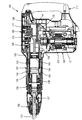
以下、本発明の実施の形態であるハンマにつき、図面を参照しつつ詳細に説明する。本実施の形態に係るハンマ101の全体構成が図1に示される。本実施の形態に係るハンマ101は、本発明の「電動往復動式工具」の一例に対応する。本実施の形態に係るハンマ101は、概括的に見て、モータハウジング105、ギアハウジング107およびハンドグリップ111を有する本体部103によってその外郭が形成される。そしてハンマ101の本体部103の先端側(図中左側端部領域)には、ハンマビット取付けチャック109を介してハンマビット113が取付けられている。ハンマビット113は、本発明における「工具ビット」に対応している。
Hereinafter, a hammer according to an embodiment of the present invention will be described in detail with reference to the drawings. The overall configuration of the
モータハウジング105内には駆動モータ121が配置されている。またギアハウジング107内には、クランク機構131、エアシリンダ機構133、打撃力伝達機構135が配置される。ギアハウジング107のうち、打撃力伝達機構135の先端側(図1において左端側)には上記ハンマビット113を保持するツールホルダ137が配置される。なおギアハウジング107内の各機構のうちクランク機構131については、駆動モータ121の出力軸123からの回転出力を適宜運動変換してハンマビット113に伝達し、当該ハンマビット113にハンマ動作を行なわせる。ツールホルダ137は、ハンマビット113につき、その長軸方向への相対的な往復動が可能に、かつその周方向への相対的な回動が規制された状態で保持する。
A
ハンマ101のクランク機構131を中心とした主要部の詳細な構成が図2に示される。ギアハウジング107内のクランク機構131は、ハウジングキャップ108の直下領域において、駆動モータ121の出力軸123のギア部125と噛み合い係合する変速ギア141、当該変速ギア141と一体状に回転するギアシャフト143、ギアシャフト143の回転を軸支するギアシャフト支持ベアリング145、ギアシャフト143の回転中心から所定距離偏心した位置において変速ギア141と一体状に形成されたクランクピン147を有する。クランクピン147はクランクアーム159の一端側に連接される。クランクアーム159の他端側は、連接ピン161を介してエアシリンダ機構131(図1参照)を構成するシリンダ165のボア内に配置された駆動子163に連接される。駆動子163は、シリンダ165内を摺動することで、いわゆる空気バネの作用を介し、ストライカ134(図1参照)を直線状に駆動し、更に中間子としてのインパクトボルト136を介してハンマビット129に対する衝撃荷重を発生させる。ストライカ134は、本発明における「打撃子」に対応する。
FIG. 2 shows a detailed configuration of the main part centering on the
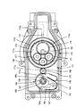
ハンマビット113を駆動する際の制振を行うカウンタウェイト171を駆動するカウンタウェイト駆動機構173の構成が図2〜図4に示される。カウンタウェイト171は、ハウジングキャップ108の上方領域に配置され、ハンマビット113の長軸方向と同方向に直線状に移動可能とされる。すなわち、カウンタウェイト171は、ハンマビット113の長軸方向と同方向に延在するガイド孔171bを有し、このガイド孔171bに貫通された複数本(本実施の形態では2本)ガイドピン172によってハンマビット113の長軸方向と同方向に直線運動するように案内される。なおガイドピン172は、ハウジングキャップ108に固定状に設けられている。
The structure of a
カウンタウェイト駆動機構173は、カウンタウェイト171に、例えばストライカ134の直線運動と対向状に直線運動を行わせるべく設けられており、クランク機構131とカウンタウェイト171との中間位置に配置されている。カウンタウェイト駆動機構173は、インターナルギア175、当該インターナルギア175の内歯175aに複数(本実施の形態では3個)のアイドルギア177を介して噛み合い係合する遊星歯車179、遊星歯車179および各アイドルギア177をそれぞれ回転自在に支持するキャリア181、遊星歯車179のキャリア181に対する回転中心から所定距離偏心した位置において当該遊星歯車179と一体状に形成されたカウンタウェイト駆動ピン183を主体にして構成されている。カウンタウェイト駆動ピン183は、本発明における「動力伝達部」に対応する。
The
キャリア181は、キャリア支持ベアリング182を介してハウジングキャップ108に回転自在に支持されるとともに、下面側に形成された係合凹部181aにクランク機構131におけるクランクピン147の先端ピン部147aが係合されており、当該クランクピン147の回転に基づき変速ギア141の回転軸線と平行な軸線回りに回転される。遊星歯車179は、軸部179aがキャリア181に回転自在に支持され、また各アイドルギア177も軸部177aがキャリア181に回転自在に支持される。インターナルギア175は、ハウジングキャップ108に回転自在に支持されるとともに、キャリア上面と直接にあるいは間接的に接触されており、当該接触部位の摩擦力あるいはギアハウジング107内に封入されるグリースを介してキャリア181の回転力が付与される構成とされる。なおインターナルギア175に付加される回転力としては、上記のほかに、遊星歯車179とキャリア181との摩擦に基づく遊星歯車179の公転(インターナルギア175の中心回りの周回移動)により作用する回転力、あるいはカウンタウェイト駆動ピン183が駆動しようとしているカウンタウェイト171からの反力による回転力がある。そしてインターナルギア175は、常時には後述する回転規制機構185によって回転を規制され、あるいは許容される構成とされる。カウンタウェイト駆動機構173および回転規制機構185は、本発明における「動力伝達機構」に対応する。
The
カウンタウェイト駆動ピン183は、カウンタウェイト171に形成されたハンマビット113の長軸方向と直交する方向に延在する直線状の長孔171aに摺動自在に嵌合されている。そしてインターナルギア175の回転が規制された状態で、クランクピン147によってキャリア181が回転されると、インターナルギア175とアイドルギア177を介して噛み合い係合する遊星歯車179が、軸部179aを中心として回転しつつ、インターナルギア175の回転中心回りに周回移動されるとき、ハンマビット113の長軸方向の運動成分によってカウンタウェイト171を直線運動させる。そしてこのカウンタウェイト171の直線運動は、例えば、前述したクランク機構131によりエアシリンダ機構133を介して駆動されるストライカ134の直線運動に概ね対向するように設定される。なお、なお、以下の説明では、遊星歯車179の軸部179aを中心とする回転を自転、遊星歯車179のインターナルギア175中心回りの周回移動を公転という場合もある。
The
インターナルギア175の回転を規制する回転規制機構185につき、図2〜図5を参照して説明する。なお図5は、回転規制機構185の作動態様を示しており、図3および図4の裏面視として描いてある。回転規制機構185は、インターナルギア175の回転規制位置を変えることによってカウンタウェイト駆動ピン183のハンマビット長軸方向への移動量(駆動量)を可変とし、これによってカウンタウェイト駆動ピン183によって駆動されるカウンタウェイト171のハンマビット長軸方向への直線運動量を可変とするものであり、カウンタウェイト171の駆動量調整手段を構成している。インターナルギア175は、外周面に外歯175bを有する外歯付インターナルギアとして構成される。回転規制機構185は、カム付ギア187、当該カム付ギア187が一方向にのみ回転することを許容するワンウェイクラッチ189、カム付ギア187の回転を規制する第1および第2ストッパ191,193(図3および図4参照)、ハンマビット113の長軸方向の移動動作(ツールホルダ137に対する出入動作)に連動して第1および第2ストッパ191,193を回転規制位置と回転規制解除位置との間で切替移動させるべく動作する切替ロッド195、当該切替ロッド195の動作に基づき第1および第2ストッパ191,193を回転規制位置あるいは回転規制解除位置へと移動するべく連動させる第1および第2リーフスプリング197,199(図3および図4参照)を主体として構成される。
The
カム付ギア187は、ハウジングキャップ108に設けたギア軸187aにワンウェイクラッチ189を介して一方向にのみ回転可能に取り付けられるとともに、外歯付インターナルギア175の外歯175bにアイドルギア186を介して噛み合い係合する。カム付ギア187のカム188は、当該カム付ギア187に一体状に設けられた円筒部からなり、外周面の一箇所に係合部188aを有する。図3および図4に示すように、第1および第2ストッパ191,193は、カム付ギア187のカム188を挟んで対向状に配置されるとともに、各一端部が共通の支持軸192を介してハウジングキャップ108に回動自在に支持されており、先端部(他端部)には、カム188の係合部188aに係合可能な爪191a,193aを有する。すなわち、第1ストッパ191の爪191aあるいは第2ストッパ193の爪193aがカム188の係合部188aに係合することによってカム付ギア187の回転を規制し、これによって外歯付インターナルギア175の回転を規制する構成とされる。第1および第2ストッパ191,193の爪191a,193aがカム188の係合部188aに係合可能な位置が上記の回動規制位置に相当し、係合が解除される位置が上記の回転規制解除位置に相当する。
The cam-equipped
切替ロッド195は、シリンダ165の外側領域に当該シリンダ165の長軸方向と平行に配置されるとともに、一端がシリンダ165の外周領域に配置されたスライドスリーブ194(図1参照)に当接され、他端が第1ストッパ191に当接されている。なお切替ロッド195は、ギアハウジング107に摺動自在に設けられている。スライドスリーブ194は、スライドスリーブ付勢スプリング196によってハンマビット113側に向って付勢されており、クッション体138(図1参照)を介してツールホルダ137に当接する位置に保持されている。そしてスライドスリーブ194がスライドスリーブ付勢スプリング196に抗して図中右方向へ移動されたときは、切替ロッド195が第1ストッパ191を背面側から加圧し、当該第1ストッパ191の爪191aをカム188の係合部188aから離脱する方向へと回動変位させる。このとき、第2ストッパ193は、第1リーフスプリング197により当該第2ストッパ193の爪193aがカム188の係合部188aに係合する方向へと回動変位される。なお第2リーフスプリング199は、切替ロッド195の加圧によって第1ストッパ191が回動変位されるとき、当該第1ストッパ191に押されて弾性変形される。このため、切替ロッド195による第1ストッパ191の加圧力が解除されたときは、当該第2リーフスプリング199は、その復元力によって第1ストッパ191を当該第1ストッパ191の爪191aがカム188の係合部188aに係合する方向へと回動させる。このとき、当該第1ストッパ191が第2ストッパ193を当該第2ストッパ193の爪193aがカム188の係合部から離脱する方向へと回動変位させる。すなわち、第1および第2リーフスプリング197,199は、第1ストッパ191と第2ストッパ193とを相互に同方向へ回動変位するように連動させる手段として設けられている。
The switching
本実施の形態に係るハンマ101は上記のように構成される。すなわち、本実施の形態にかかるハンマ101は、外歯付インターナルギア175の回転規制位置を変えることによって、カウンタウェイト駆動ピン183のハンマビット長軸方向への移動量(駆動量)を可変とし、これによってカウンタウェイト駆動ピン183によって駆動されるカウンタウェイト171のハンマビット長軸方向への直線運動量を可変とする構成を採用したものであり、その原理は、下記のとおりである。
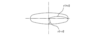
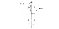
本実施の形態においては、外歯付インターナルギア175の内歯175aの歯数と、遊星歯車179の歯数は2:1の比率に設定されている。換言すれば、遊星歯車179は、外歯付インターナルギア175の中心回りに1回の周回動作をするとき、当該遊星歯車179の中心回りに2回の自転動作をするように設定されている。また外歯付インターナルギア175の外歯175bの歯数と、カム付ギア187の歯数は、2:1に設定されている。また、図6の模式図に示すように、キャリア181の回転中心軸と遊星歯車179の回転中心軸との距離をr1とし、遊星歯車179の回転中心軸とカウンタウェイト駆動ピン183の回転中心軸との距離をr2とする。
The
In the present embodiment, the number of teeth of the
上記の設定条件において、カム付ギア187をある位置で固定(したがって、外歯付インターナルギア175を固定)し、キャリア181を回転させた場合のカウンタウェイト駆動ピン183の運動軌跡は、図7の模式図に示すように、長軸方向に(r1+r2)、短軸方向に(r1−r2)の楕円状の軌跡を描く。ここで、(r1−r2=0)であれば、カウンタウェイト駆動ピン183の短軸方向の運動量はゼロになる。カム付ギア187の上記位置を180度回転すると、図7が90度回転した図8となる。つまり、カム付ギア187を180度毎に固定すると、カウンタウェイト駆動ピン183の軌跡を図7に示す状態と図8に示す状態とに切り替えることができる。このため、カウンタウェイト駆動ピン183にカウンタウェイト171を取り付ければ、当該カウンタウェイト171をハンマビット長軸方向への直線移動量を、大きく動く場合{2×(r1+r2)}と、小さく動く場合{2×(r1−r2)}とに切り替えることができる。
Under the above setting conditions, the movement locus of the
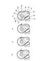
本実施の形態においては、図3に示すように、遊星歯車179がハンマビット長軸方向の後側端部領域(あるいは前側端部領域)に位置している場合において、カウンタウェイト駆動ピン183が外歯付インターナルギア175と遊星歯車179との近接部位に最も接近し、また図4に示すように、遊星歯車179がハンマビット長軸方向の後側端部領域(あるいは前側端部領域)に位置している場合において、カウンタウェイト駆動ピン183が外歯付インターナルギア175と遊星歯車179との近接部位から最も離間するように構成している。そして、図3に示す状態のときに、第2ストッパ193がカム188の係合部188aに係合して当該カム付ギア187を固定し、図4に示す状態のときに、第1ストッパ191がカム188のカム188の係合部188aに係合して当該カム付ギア187を固定する構成とされる。すなわち、第2ストッパ193と第1ストッパ191によるカム付ギア187の回転規制位置は、180度の位相差を有する構成とされている。このため、カム付ギア187の歯数に対し外歯175bの歯数比が1:2に設定された外歯付インターナルギア175は、90度の位相差で回転規制されることになる。
In the present embodiment, as shown in FIG. 3, when the
次に当該ハンマ101の作用および使用方法について説明する。まず図1に示すハンマ101のハンマビット113を被加工材に押圧して負荷を与えた駆動態様、すなわち有負荷駆動状態における作用について説明する。
Next, the operation and usage method of the
駆動モータ121が通電駆動されると、出力軸123、変速ギア141、クランクピン147、クランクアーム159、連接ピン161を介して駆動子163がシリンダ165のボア内で直線運動を行い、これによってエアシリンダ機構131および打撃力伝達機構135を介してハンマビット113が長軸方向に直線駆動される。すなわち、駆動子163がハンマビット113側へ摺動動作すると、それに伴う空気バネ作用を介してストライカ134がシリンダ165内を同方向へ直線運動してインパクトボルト136に衝突することで、その運動エネルギ(打撃力)をハンマビット113へと伝達し、これによってハンマビット113がツールホルダ137内を摺動動作して被加工材に対するハンマ作業を遂行する。
When the
ハンマ101の駆動時において、有負荷駆動状態においては、ハンマビット113の被加工材への押圧動作の反力により、スライドスリーブ付勢スプリング196の図中左方向への付勢力に対抗しつつ、スライドスリーブ194が図中右方向に移動される。スライドスリーブ194の移動により切替ロッド195が図中右方向へと移動し、第1ストッパ191を背面側から加圧してカム付ギア187のカム188に向って支持軸192回りに回動変位させる。この第1ストッパ191の回動変位に基づき第1リーフスプリング197を介して第2ストッパ193が第1ストッパ191と同方向へ回動される。これにより当該第1ストッパ191の爪191aがカム188の係合部188aから離間し、これによってカム付ギア187の回転規制が解除され、外歯付インターナルギア175の回転が許容される。
While driving the
図5には有負荷駆動状態のときの切替ロッド195による外歯付インターナルギア175の回転規制切替動作態様が示されており、上記の状態、すなわち切替ロッド195によって第1ストッパ191が加圧され、これによって当該第1ストッパ191および第2ストッパ193が回動され、外歯付インターナルギア175の回転規制が解除された状態が図5の(A)〜(C)に示されている。なお図5は図3および図4の裏面視であり、切替ロッド195による加圧力の入力方向が図3および図4の入力方向と逆向きとなる。このようにして、回転規制が解除されると、当該外歯付インターナルギア175には、キャリア181からの摩擦あるいはグリースによる回転力、遊星歯車179とキャリア181との摩擦に基づく遊星歯車179の公転により作用する回転力、あるいはカウンタウェイト駆動ピン183が駆動しようとしているカウンタウェイト171からの反力による回転力が作用しているため、カム付ギア187の回転規制が解除された瞬間に当該外歯付インターナルギア175は回転動作する。そして当該外歯付インターナルギア175が90度回転したとき、つまりカム付ギア187が180度回転したとき、図5の(D)に示すように、カム188の係合部188aに第2ストッパ193の爪193aが係合し、これによって外歯付インターナルギア175の回転を規制する。
FIG. 5 shows a rotation restriction switching operation mode of the
この状態においては、図3に示すように、遊星歯車179が外歯付インターナルギア175に対しハンマビット113の長軸方向の後側端部領域(あるいは前側端部領域)に位置した場合は、カウンタウェイト駆動ピン183は、外歯付インターナルギア175と遊星歯車179の近接部位に対し最も接近した位置に位置する関係とされる。この状態で、カウンタウェイト駆動ピン183が自転しつつ公転することにより、当該カウンタウェイト駆動ピン183が図7の模式図で示すようなハンマ101の長軸方向(図中左右方向)に対し、大きい運動量(ストローク量)を有することになる。そして当該カウンタウェイト駆動ピン183の運動量を利用して、カウンタウェイト171が、例えばストライカ134と対向状に長軸方向に駆動され、これによってハンマビット113のハンマ作業に際しての制振を効率的に行う。
In this state, as shown in FIG. 3, when the
次にハンマビット113に負荷が作用していない駆動態様、すなわち無負荷駆動状態における作用について説明する。無負荷駆動状態においては、ハンマビット113の被加工材への押圧動作の反力が作用しないことにより、スライドスリーブ付勢スプリング196の図中左方向への付勢力により、スライドスリーブ194は図中左方向に移動される。これにより切替ロッド195による第1ストッパ191の加圧力が除去(消去)される。図5の(D)に示されるように、切替ロッド195が第1ストッパ191を加圧した状態では、第2リーフスプリング199は第1ストッパ191を介して弾性変形される。このため、切替ロッド195による加圧力が除去されると、当該第2リーフスプリング199の復元力により、第1ストッパ191が押し戻されて爪193aがカム188の係合部188aに係合する側へと回動されるとともに、当該第1ストッパ191に押された第2ストッパ193がカム188から離れる方向へと回動される。これにより第2ストッパ193の爪193aがカム188の係合部188aから離脱してカム付ギア187の回転規制が解除され、外歯付インターナルギア175の回転が許容される。
Next, the driving mode in which no load is applied to the
すると外歯付インターナルギア175には、キャリア181からの摩擦あるいはグリースによる回転力、遊星歯車179とキャリア181との摩擦に基づく遊星歯車179の公転により作用する回転力、あるいはカウンタウェイト駆動ピン183が駆動しようとしているカウンタウェイト171からの反力による回転力が作用しているため、カム付ギア187の回転規制が解除された瞬間に当該外歯付インターナルギア175は回転動作する。本実施の形態では、外歯付インターナルギア175が90度回転したとき、第2ストッパ193の爪193aがカム188の係合部188aに係合することで、その回転が規制される。
Then, the externally toothed
このとき、図4に示すように、遊星歯車179が外歯付インターナルギア175に対しハンマビット113の長軸方向の後側端部領域(あるいは前側端部領域)に位置した場合は、カウンタウェイト駆動ピン183は、外歯付インターナルギア175と遊星歯車179の近接部位に対し最も離間した位置に位置する。この状態で、カウンタウェイト駆動ピン183が自転しつつ公転することにより、当該カウンタウェイト駆動ピン183が図8の模式図で示すようなハンマ101の長軸方向(図中左右方向)に対し、小さい運動量(ストローク量)を有することになる。この場合、図8において、(r1−r2=0)とすれば、外歯付インターナルギア175に対する遊星歯車179の近接位置から最も離間した位置に置かれたカウンタウェイト駆動ピン183は、遊星歯車179の公転にも拘わらず、ハンマ101の長軸方向に関しては運動量が見かけ上ゼロとなる。
At this time, as shown in FIG. 4, when the
この結果、無負荷駆動状態においては、遊星歯車179が外歯付インターナルギア175の中心回りに周回動作しても、カウンタウェイト駆動ピン183はハンマ101の長軸方向(図中左右方向)に関しては何ら運動をしないことが帰結される。換言すれば、無負荷駆動状態においては、駆動モータ121が駆動し、遊星歯車179が外歯付インターナルギア175の中心回りに周回動作をおこなっているにも拘らず、カウンタウェイト駆動ピン183は、ハンマ101の長軸方向にカウンタウェイト171を駆動しないこととなる。
As a result, in the no-load drive state, even if the
本実施の形態によれば、ハンマビット113に作用する負荷に基づいて外歯付インターナルギア175の回転を許容し、遊星歯車179と外歯付インターナルギア175の近接部位に対するカウンタウェイト駆動ピン183の位置を相対的に変化させる。これによってカウンタウェイト171の直線運動量を可変とし、ハンマ101におけるハンマビット113によるハンマ作業時の合理的な制振を行うことが可能となる。
According to the present embodiment, rotation of the
本実施の形態においては、カム付ギア187は、ワンウェイクラッチ189を介して一方向にしか回転できない構成としている。このため、カム188の係合部188aに対して第1ストッパ191の爪191aあるいは第2ストッパ193の爪193aが係合するだけで、すなわち、回転が許容された方向への回転のみを規制するだけで、カム付ギア187および外歯付インターナルギア175を双方向にガタツキを伴うことなく確実に固定することができる。例えば、インターナルギアを固定する場合において、双方向に回転を許容されたインターナルギアを固定する構成であれば、双方向につきそれぞれ回転を規制しない限り、いわゆるガタツキが生じてしまう。本実施の形態によれば、上記のように、外歯付インターナルギア175を予め設定された位置に確実に固定することができるため、固定位置精度を向上することが可能となるとともに、動作の安定化を図ることができる。
In the present embodiment, the
また本実施の形態においては、外歯付インターナルギア175の外歯175bに噛み合い係合するカム付ギア187を固定することで、当該外歯付インターナルギア175の回転を固定する構成としている。すなわち、外歯付インターナルギア175よりも小さいカム付ギア187を固定する構成のため、外歯付インターナルギア175の回転規制機構185を構成するに際し、例えば外歯付インターナルギア175を直接に固定する構成に比べて回転規制機構185のコンパクト化が可能になるとともに、レイアウト上の自由度を得ることができる。
In this embodiment, the rotation of the
また本実施の形態では、遊星歯車179は、外歯付インターナルギア175に対しアイドルギア177を介して噛み合い係合される構成とされる。かかる構成によれば、外歯付インターナルギア175に対する遊星歯車179の周回半径位置(自転の中心位置)の設定、すなわちカウンタウェイト駆動ピン183の配置位置の設定につき自由度を得ることができる。例えば、遊星歯車179が外歯付インターナルギア175に対して直接に噛み合い係合する構成であれば、外歯付インターナルギア175に対する遊星歯車179の周回半径は、一箇所に限定されてしまうこととなるが、本実施の形態のように、アイドルギア177を介在したときは、かかる限定を受けることなく適宜に定めることが可能となる。これにより、カウンタウェイト駆動ピン183の工具ビット長軸方向運動成分を任意に設定することができる。
In the present embodiment, the
また遊星歯車179がインターナルギア175に直接に噛み合い係合する方式の場合であれば、例えば、カウンタウェイト駆動ピン183に直線運動を行わせるには、遊星歯車179の中心から当該遊星歯車上のカウンタウェイト駆動ピン183中心までの距離と、遊星歯車179の中心からインターナルギア175の中心(遊星ギア179の公転の中心)までの距離とが等しくなるように設定しなければならず、そのためには、カウンタウェイト駆動ピン183を遊星歯車179のピッチ円上に設けなければならない。しかるに、本発明によれば、インターナルギア175に対し遊星歯車179がアイドルギア177を介して噛み合う構成としたことにより、上記のような制約が解消され、遊星歯車179に対するカウンタウェイト駆動ピン183の設定位置を任意に定めることが可能となる。またカウンタウェイト駆動ピン183を遊星歯車179のピッチ円上に設けるには、例えば図6において、遊星歯車179の上面とカウンタウェイト駆動ピン183の下端面との間に介在物が必要とされる。その結果、カウンタウェイト駆動ピン183の軸方向高さ(長さ)が大となり、本体部103の駆動モータ121軸線方向寸法が大きくなるとか、遊星歯車179に作用するカウンタウェイト駆動時の反力によるモーメントが大きくなるといった弊害が生じるが、本実施の形態によれば、こういった問題を解消できる。
In the case of a system in which the
なお上述した実施の形態においては、ハンマ101のハンマビット113がハンマ作業を遂行する際の制振を行うカウンタウェイト171の直線運動量を可変とする場合として説明したが、ハンマビット113を駆動する駆動機構の直線運動量(ストローク量)を可変とする態様で適用することも可能である。
すなわち、ハンマビット113の有負荷駆動状態と無負荷駆動状態とでクランクアーム159の運動量を可変とする構成である。このために、特に図示はしないが、前述した実施の形態において、図2〜図8を用いて説明した、外歯付インターナルギア175、遊星歯車179、カウンタウェイト駆動ピン183等から構成されるカウンタウェイト駆動機構173と同等のクランクアーム駆動機構が構成される。そして当該クランクアーム駆動機構は、クランク機構131中の、具体的には図2に示された駆動モータ121の回転出力によって回転駆動される変速ギア141と、クランクアーム159との間に介在され、これによってクランクアーム159を駆動する構成とする。更に当該クランクアーム駆動機構における外歯付インターナルギア175の回転規制位置を、上述した実施の形態で説明したカム付ギア187、ワンウェイクラッチ189、第1および第2ストッパ191,193、切替ロッド195等から構成される回転規制機構185と同等の回転規制機構によって可変とする。
In the above-described embodiment, the case where the
That is, the momentum of the
かかる構成を採用することによって、ハンマビット113に作用する負荷に基づいて外歯付インターナルギア175の所定量の回転を許容することにより、当該外歯付インターナルギア175と遊星歯車179の近接部位に対するクランクピン147の位置を相対的に変化させることが可能とされ、これによってクランクアーム159の直線運動量を可変とし、延いては駆動子163の直線運動量を可変とすることができる。
By adopting such a configuration, a predetermined amount of rotation of the external toothed
上記発明の趣旨に鑑み、下記のごとき態様が構成可能である。
(態様1)
「請求項1に記載の電動往復動式工具であって、
前記工具ビットに作用する負荷に基づいて前記インターナルギアの回転を許容することにより、前記インターナルギアに対する遊星歯車の近接部位が、前記工具ビットの長軸方向の前側端部領域ないし後側端部領域にあるときに、前記動力伝達部が当該近接部位ないしその近傍に配置されるように構成されていることを特徴とする電動往復動式工具。」
In view of the gist of the invention, the following aspects can be configured.
(Aspect 1)
“Electric reciprocating tool according to
By allowing the internal gear to rotate based on the load acting on the tool bit, the proximity portion of the planetary gear with respect to the internal gear has a front end region or a rear end region in the longitudinal direction of the tool bit. The electric power reciprocating tool is configured such that the power transmission portion is disposed in the proximity portion or in the vicinity thereof. "
このように構成すれば、遊星歯車がインターナルギアの中心回りに周回することで、動力伝達部は、上記前側端部領域および後側端部領域との間で工具ビットの長軸方向に運動することが可能となり、動力伝達部の工具ビット長軸方向への運動のストロークを大きく確保することが可能となる。 If comprised in this way, a planetary gear will go around the center of an internal gear, and a power transmission part will move to the long-axis direction of a tool bit between the said front side edge part area | region and a rear side edge part area | region. Therefore, it is possible to ensure a large stroke of movement of the power transmission portion in the tool bit long axis direction.
(態様2)
「請求項1または態様1に記載の電動往復動式工具であって、
前記工具ビットに作用する負荷に基づいて前記インターナルギアの回転を許容することにより、前記インターナルギアと遊星歯車の近接部位が、前記工具ビットの長軸方向の前側端部領域ないし後側端部領域にあるときに、動力伝達部が遊星歯車のうち当該近接部位と対向する側の周縁領域に配置されるように構成されていることを特徴とする電動往復動式工具。」
(Aspect 2)
"Electric reciprocating tool according to
By allowing the internal gear to rotate based on the load acting on the tool bit, the proximity part of the internal gear and the planetary gear is located at the front end region or the rear end region in the longitudinal direction of the tool bit. The electric reciprocating tool is configured such that the power transmission portion is arranged in a peripheral region on the side of the planetary gear that faces the adjacent portion. "
このように構成すれば、遊星歯車がインターナルギアの中心回りに周回することで、動力伝達部は、上記近接部位と対向する側の領域において工具ビットの長軸方向に運動することが可能となる。かかる構成により動力伝達部の工具ビット長軸方向への運動のストロークを小さくすることが可能となる。 If comprised in this way, a planetary gear will go around the center of an internal gear, and it will become possible for a power transmission part to move to the major axis direction of a tool bit in the field of the side facing the above-mentioned proximity part. . With this configuration, it is possible to reduce the movement stroke of the power transmission unit in the tool bit long axis direction.
(態様3)
「態様1または2に記載の電動往復動式工具であって、
前記遊星歯車は、インターナルギアの中心回りに1回の周回動作をするとき、当該遊星歯車の中心回りに2回の自転動作をするように設定されていることを特徴とする電動往復動式工具。」
(Aspect 3)
“Electric reciprocating tool according to
The planetary gear is set so as to rotate twice around the center of the planetary gear when the planetary gear makes one rounding around the center of the internal gear. . "
このように構成すれば、動力伝達部の工具ビット長軸方向への運動の周期性を確保することができる。 If comprised in this way, the periodicity of the exercise | movement to the tool bit long-axis direction of a power transmission part is securable.
101 ハンマ
103 本体部
105 モータハウジング
107 ギアハウジング
108 ハウジングキャップ
109 ハンマビット取付けチャック
111 ハンドグリップ
113 ハンマビット(工具ビット)
121 駆動モータ
123 出力軸
125 出力軸ギア部
131 クランク機構
133 エアシリンダ機構
134 ストライカ(打撃子)
135 打撃力伝達機構
136 インパクトボルト
137 ツールホルダ
138 クッション体
141 変速ギア
143 ギアシャフト
145 ギアシャフト支持ベアリング
147 クランクピン
147a 先端ピン部
159 クランクアーム
161 連接ピン
163 駆動子
165 シリンダ
171 カウンタウェイト
171a 長孔
171b ガイド孔
172 ガイドピン
173 カウンタウェイト駆動機構(動力伝達機構)
175 外歯付インターナルギア
175a 内歯
175b 外歯
177 アイドルギア
177a 軸部
179 遊星歯車
179a 軸部
181 キャリア
181a 係合凹部
182 キャリア支持ベアリング
183 カウンタウェイト駆動ピン(動力伝達部)
185 回転規制機構(動力伝達機構)
186 アイドルギア
187 カム付ギア
188 カム
188a 係合部
189 ワンウェイクラッチ
191 第1ストッパ
191a 爪
192 支持軸
193 第2ストッパ
193a 爪
194 スライドスリーブ
195 切替ロッド
196 スライドスリーブスプリング
197 第1リーフスプリング
199 第2リーフスプリング
101
121
135 Impact
175
185 Rotation restriction mechanism (power transmission mechanism)
186
Claims (6)
前記工具ビットを駆動するための駆動モータと、
前記駆動モータの回転出力を前記工具ビット長軸方向への直線運動に変換する動力伝達機構を有する電動往復動式工具であって、
前記動力伝達機構は、
回転自在に支持されたインターナルギアと、
前記駆動モータの回転出力によって駆動されて前記インターナルギアの中心回りを周回する遊星歯車と、
前記遊星歯車に偏心状に設けられた動力伝達部と、
常時には前記インターナルギアの回転を規制する回転規制機構と、を有し、
前記工具ビットに作用する負荷に基づいて、前記回転規制機構による前記インターナルギアの回転の規制を解除することで当該インターナルギアの所定方向への所定量の回転を許容し、これによって前記インターナルギアと前記遊星歯車の近接部位に対する前記動力伝達部の位置を相対的に変化させることで、当該動力伝達部の前記工具ビット長軸方向への運動量を変化させる構成とされ、
更に前記インターナルギアにつき、前記回転規制機構による当該インターナルギアの回転の規制が解除された状態において前記所定方向への回転を許容し、かつこれとは反対側への回転を規制するための手段を備えていることを特徴とする電動往復動式工具。 A tool bit that performs machining on the workpiece by linear motion;
A drive motor for driving the tool bit;
An electric reciprocating tool having a power transmission mechanism for converting the rotational output of the drive motor into linear motion in the tool bit long axis direction,
The power transmission mechanism is
An internal gear supported rotatably,
A planetary gear driven by the rotational output of the drive motor and revolving around the center of the internal gear;
A power transmission portion provided eccentrically on the planetary gear;
A rotation restricting mechanism for restricting the rotation of the internal gear at all times,
Based on the load acting on the tool bit, by releasing the restriction of the rotation of the internal gear by the rotation restriction mechanism, a predetermined amount of rotation in the predetermined direction of the internal gear is allowed, and thereby the internal gear and By changing the position of the power transmission unit relative to the proximity of the planetary gear, the momentum of the power transmission unit in the tool bit long axis direction is changed,
Furthermore, for the internal gear , means for allowing the rotation in the predetermined direction in a state in which the rotation restriction of the internal gear by the rotation restriction mechanism is released and restricting the rotation to the opposite side. electric reciprocating tool characterized in that it comprises.
前記工具ビットは、打撃子による打撃力を受承して被加工材にハンマ作業を行うハンマビットとして構成され、
前記動力伝達部は、カウンタウェイトの駆動に用いられることを特徴とする電動往復動式工具。 The electric reciprocating tool according to claim 1,
The tool bit is configured as a hammer bit that receives a striking force by a striker and performs a hammering operation on a workpiece.
The power transmission unit is used to drive a counterweight, and is an electric reciprocating tool.
前記工具ビットは、打撃子による打撃力を受承して被加工材にハンマ作業を行うハンマビットとして構成され、
前記動力伝達部は、前記打撃子を前記ハンマビット長軸方向へ直線状に駆動させるためのクランクアームに接続されていることを特徴とする電動往復動式工具。 The electric reciprocating tool according to claim 1,
The tool bit is configured as a hammer bit that receives a striking force by a striker and performs a hammering operation on a workpiece.
The electric power reciprocating tool is characterized in that the power transmission unit is connected to a crank arm for driving the striker linearly in the longitudinal direction of the hammer bit.
前記インターナルギアは、外周面に外歯が形成された外歯付インターナルギアとして構成されており、前記回転規制機構は、前記外歯付インターナルギアの外歯に噛み合い係合するギアを固定することで当該外歯付インターナルギアの回転を規制し、前記ギアの固定を解除することで当該外歯付インターナルギアの回転を許容する構成としたことを特徴とする電動往復動式工具。 The electric reciprocating tool according to any one of claims 1 to 3,
The internal gear is configured as an external gear with external teeth having external teeth formed on an outer peripheral surface, and the rotation restricting mechanism fixes a gear that meshes with and engages with external teeth of the external gear with external teeth. The electric reciprocating tool is configured to restrict the rotation of the external gear with external teeth and to allow the rotation of the internal gear with external teeth by releasing the fixing of the gear.
前記回転規制機構による前記インターナルギアの回転の規制が解除された状態において前記インターナルギアが、前記所定方向へ回転することを許容し、かつこれとは反対側へ回転することを規制する手段としてワンウェイクラッチを備えていることを特徴とする電動往復動式工具。 The electric reciprocating tool according to any one of claims 1 to 4,
One-way as means for allowing the internal gear to rotate in the predetermined direction and restricting the rotation to the opposite side in a state where the restriction of rotation of the internal gear by the rotation restricting mechanism is released. An electric reciprocating tool characterized by comprising a clutch.
前記遊星歯車は、前記インターナルギアに対しアイドルギアを介して噛み合い係合されることを特徴とする電動往復動式工具。 The electric reciprocating tool according to any one of claims 1 to 5,
The reciprocating tool according to claim 1, wherein the planetary gear is engaged with and engaged with the internal gear via an idle gear.
Priority Applications (4)
| Application Number | Priority Date | Filing Date | Title |
|---|---|---|---|
| JP2004237255A JP4527468B2 (en) | 2004-08-17 | 2004-08-17 | Electric tool |
| EP05017510A EP1627708B9 (en) | 2004-08-17 | 2005-08-11 | Power tool |
| US11/201,085 US7143842B2 (en) | 2004-08-17 | 2005-08-11 | Power tool |
| DE602005011536T DE602005011536D1 (en) | 2004-08-17 | 2005-08-11 | power tool |
Applications Claiming Priority (1)
| Application Number | Priority Date | Filing Date | Title |
|---|---|---|---|
| JP2004237255A JP4527468B2 (en) | 2004-08-17 | 2004-08-17 | Electric tool |
Publications (2)
| Publication Number | Publication Date |
|---|---|
| JP2006055914A JP2006055914A (en) | 2006-03-02 |
| JP4527468B2 true JP4527468B2 (en) | 2010-08-18 |
Family
ID=35170181
Family Applications (1)
| Application Number | Title | Priority Date | Filing Date |
|---|---|---|---|
| JP2004237255A Expired - Fee Related JP4527468B2 (en) | 2004-08-17 | 2004-08-17 | Electric tool |
Country Status (4)
| Country | Link |
|---|---|
| US (1) | US7143842B2 (en) |
| EP (1) | EP1627708B9 (en) |
| JP (1) | JP4527468B2 (en) |
| DE (1) | DE602005011536D1 (en) |
Families Citing this family (27)
| Publication number | Priority date | Publication date | Assignee | Title |
|---|---|---|---|---|
| US7711487B2 (en) | 2006-10-10 | 2010-05-04 | Halliburton Energy Services, Inc. | Methods for maximizing second fracture length |
| US7841394B2 (en) * | 2005-12-01 | 2010-11-30 | Halliburton Energy Services Inc. | Method and apparatus for centralized well treatment |
| US7836949B2 (en) * | 2005-12-01 | 2010-11-23 | Halliburton Energy Services, Inc. | Method and apparatus for controlling the manufacture of well treatment fluid |
| US7946340B2 (en) * | 2005-12-01 | 2011-05-24 | Halliburton Energy Services, Inc. | Method and apparatus for orchestration of fracture placement from a centralized well fluid treatment center |
| US7740072B2 (en) * | 2006-10-10 | 2010-06-22 | Halliburton Energy Services, Inc. | Methods and systems for well stimulation using multiple angled fracturing |
| US20070125544A1 (en) * | 2005-12-01 | 2007-06-07 | Halliburton Energy Services, Inc. | Method and apparatus for providing pressure for well treatment operations |
| GB0616351D0 (en) * | 2006-08-17 | 2006-09-27 | Futuretec Ltd | Turbulent flow tool |
| DE102006053105A1 (en) * | 2006-11-10 | 2008-05-15 | Robert Bosch Gmbh | Hand tools percussion device |
| US8485274B2 (en) * | 2007-05-14 | 2013-07-16 | Makita Corporation | Impact tool |
| US7832498B2 (en) | 2007-06-15 | 2010-11-16 | Makita Corporation | Impact tool |
| US7931082B2 (en) * | 2007-10-16 | 2011-04-26 | Halliburton Energy Services Inc., | Method and system for centralized well treatment |
| US7861799B2 (en) * | 2008-03-21 | 2011-01-04 | Makita Corporation | Impact tool |
| DE102009029055A1 (en) * | 2009-09-01 | 2011-03-10 | Robert Bosch Gmbh | Drilling and / or chiselling device |
| US9339938B2 (en) | 2010-10-08 | 2016-05-17 | Milwaukee Electric Tool Corporation | Powered cutting tool |
| USD668922S1 (en) | 2012-01-20 | 2012-10-16 | Milwaukee Electric Tool Corporation | Powered cutting tool |
| DE112013004324T5 (en) * | 2012-09-03 | 2015-06-03 | Makita Corporation | hammer tool |
| EP3189940B1 (en) * | 2012-12-25 | 2018-01-31 | Makita Corporation | Impact tool |
| EP3074184A2 (en) * | 2013-11-26 | 2016-10-05 | Hitachi Koki Co., Ltd. | Electrical power tool |
| JP6863704B2 (en) | 2016-10-07 | 2021-04-21 | 株式会社マキタ | Strike tool |
| US10875168B2 (en) | 2016-10-07 | 2020-12-29 | Makita Corporation | Power tool |
| EP3697574A1 (en) | 2017-10-20 | 2020-08-26 | Milwaukee Electric Tool Corporation | Percussion tool |
| JP6987599B2 (en) * | 2017-10-20 | 2022-01-05 | 株式会社マキタ | Strike tool |
| WO2019147919A1 (en) | 2018-01-26 | 2019-08-01 | Milwaukee Electric Tool Corporation | Percussion tool |
| WO2019195508A1 (en) | 2018-04-04 | 2019-10-10 | Milwaukee Electric Tool Corporation | Rotary hammer |
| JP7246202B2 (en) | 2019-02-19 | 2023-03-27 | 株式会社マキタ | Power tool with vibration mechanism |
| JP7229807B2 (en) | 2019-02-21 | 2023-02-28 | 株式会社マキタ | Electric tool |
| CN112393890B (en) * | 2020-11-20 | 2023-05-05 | 中航飞机起落架有限责任公司 | Pulling load loading device and method for fatigue test |
Citations (2)
| Publication number | Priority date | Publication date | Assignee | Title |
|---|---|---|---|---|
| JP2002079476A (en) * | 2000-07-14 | 2002-03-19 | Hilti Ag | Impact type power tool device |
| JP2004216484A (en) * | 2003-01-10 | 2004-08-05 | Makita Corp | Electric reciprocating tool |
Family Cites Families (15)
| Publication number | Priority date | Publication date | Assignee | Title |
|---|---|---|---|---|
| DE3116851A1 (en) * | 1981-04-28 | 1982-11-11 | Hilti AG, 9494 Schaan | DRILL AND CHISEL HAMMER |
| DE3807078A1 (en) * | 1988-03-04 | 1989-09-14 | Black & Decker Inc | DRILLING HAMMER |
| JPH01274907A (en) * | 1988-09-14 | 1989-11-02 | Matsushita Electric Works Ltd | Hammer drill |
| DE3922357C2 (en) * | 1989-07-07 | 1994-02-17 | Atlas Copco Elektrowerkzeuge | Electropneumatic hammer drill |
| JPH0431801A (en) | 1990-05-28 | 1992-02-04 | Yoshiyuki Aomi | Variable optical attenuator |
| DE4038586A1 (en) * | 1990-12-04 | 1992-06-11 | Bosch Gmbh Robert | HAND MACHINE TOOL WITH Eccentric Gear |
| JPH0810019B2 (en) * | 1990-12-26 | 1996-01-31 | 日本電池株式会社 | Planetary gear shifting mechanism incorporating a one-way clutch |
| JP3292972B2 (en) * | 1996-03-29 | 2002-06-17 | 株式会社マキタ | Impact tool |
| JP4281273B2 (en) * | 2000-10-20 | 2009-06-17 | 日立工機株式会社 | Hammer drill |
| GB0100605D0 (en) * | 2001-01-10 | 2001-02-21 | Black & Decker Inc | Hammer |
| JP2002239835A (en) | 2001-02-16 | 2002-08-28 | Makita Corp | Reciprocating type tool |
| JP3730153B2 (en) * | 2001-10-18 | 2005-12-21 | セイコーインスツル株式会社 | Printer cutter device |
| DE10225239A1 (en) * | 2002-06-06 | 2003-12-18 | Hilti Ag | Mode selector switch for combined electric hand machine tool |
| JP3843914B2 (en) * | 2002-08-27 | 2006-11-08 | 松下電工株式会社 | Hammer drill |
| JP3976187B2 (en) * | 2002-11-20 | 2007-09-12 | 株式会社マキタ | Hammer drill |
-
2004
- 2004-08-17 JP JP2004237255A patent/JP4527468B2/en not_active Expired - Fee Related
-
2005
- 2005-08-11 US US11/201,085 patent/US7143842B2/en not_active Expired - Fee Related
- 2005-08-11 EP EP05017510A patent/EP1627708B9/en not_active Not-in-force
- 2005-08-11 DE DE602005011536T patent/DE602005011536D1/en active Active
Patent Citations (2)
| Publication number | Priority date | Publication date | Assignee | Title |
|---|---|---|---|---|
| JP2002079476A (en) * | 2000-07-14 | 2002-03-19 | Hilti Ag | Impact type power tool device |
| JP2004216484A (en) * | 2003-01-10 | 2004-08-05 | Makita Corp | Electric reciprocating tool |
Also Published As
| Publication number | Publication date |
|---|---|
| EP1627708B1 (en) | 2008-12-10 |
| EP1627708B9 (en) | 2009-08-26 |
| US20060048958A1 (en) | 2006-03-09 |
| DE602005011536D1 (en) | 2009-01-22 |
| JP2006055914A (en) | 2006-03-02 |
| US7143842B2 (en) | 2006-12-05 |
| EP1627708A1 (en) | 2006-02-22 |
Similar Documents
| Publication | Publication Date | Title |
|---|---|---|
| JP4527468B2 (en) | Electric tool | |
| JP4270887B2 (en) | Electric reciprocating tool | |
| EP1997591B1 (en) | Electric hammer | |
| JP4659737B2 (en) | Work tools | |
| JP5202997B2 (en) | Work tools | |
| JP5336781B2 (en) | Work tools | |
| JP5147488B2 (en) | Work tools | |
| JP2008183633A (en) | Hammer drill | |
| US20050028996A1 (en) | Impact drill | |
| JP4456559B2 (en) | Work tools | |
| JP2017042887A (en) | Hammering tool | |
| JP6517634B2 (en) | Impact tool | |
| US20050028995A1 (en) | Impact drill | |
| EP2127820A1 (en) | Driving tool | |
| JP4805288B2 (en) | Electric hammer | |
| JP4243093B2 (en) | Electric hammer | |
| JPH06210507A (en) | Motive power changeover mechanism in rotary tool | |
| JP2000291762A (en) | Reciprocating mechanism and electric tool using the same | |
| JP7388873B2 (en) | impact tool | |
| JP7388875B2 (en) | impact tool | |
| JP7060098B2 (en) | Electric tool | |
| JP4757043B2 (en) | Work tools | |
| JP2016140934A (en) | Power tool | |
| JP4485462B2 (en) | Work tools |
Legal Events
| Date | Code | Title | Description |
|---|---|---|---|
| A621 | Written request for application examination |
Free format text: JAPANESE INTERMEDIATE CODE: A621 Effective date: 20070216 |
|
| A977 | Report on retrieval |
Free format text: JAPANESE INTERMEDIATE CODE: A971007 Effective date: 20080827 |
|
| A131 | Notification of reasons for refusal |
Free format text: JAPANESE INTERMEDIATE CODE: A131 Effective date: 20090805 |
|
| A521 | Request for written amendment filed |
Free format text: JAPANESE INTERMEDIATE CODE: A523 Effective date: 20091002 |
|
| TRDD | Decision of grant or rejection written | ||
| A01 | Written decision to grant a patent or to grant a registration (utility model) |
Free format text: JAPANESE INTERMEDIATE CODE: A01 Effective date: 20100511 |
|
| A01 | Written decision to grant a patent or to grant a registration (utility model) |
Free format text: JAPANESE INTERMEDIATE CODE: A01 |
|
| A61 | First payment of annual fees (during grant procedure) |
Free format text: JAPANESE INTERMEDIATE CODE: A61 Effective date: 20100603 |
|
| FPAY | Renewal fee payment (event date is renewal date of database) |
Free format text: PAYMENT UNTIL: 20130611 Year of fee payment: 3 |
|
| R150 | Certificate of patent or registration of utility model |
Free format text: JAPANESE INTERMEDIATE CODE: R150 |
|
| FPAY | Renewal fee payment (event date is renewal date of database) |
Free format text: PAYMENT UNTIL: 20130611 Year of fee payment: 3 |
|
| FPAY | Renewal fee payment (event date is renewal date of database) |
Free format text: PAYMENT UNTIL: 20130611 Year of fee payment: 3 |
|
| R250 | Receipt of annual fees |
Free format text: JAPANESE INTERMEDIATE CODE: R250 |
|
| LAPS | Cancellation because of no payment of annual fees |