EP2140982A1 - Rotary and/or demolition hammer - Google Patents
Rotary and/or demolition hammer Download PDFInfo
- Publication number
- EP2140982A1 EP2140982A1 EP09161057A EP09161057A EP2140982A1 EP 2140982 A1 EP2140982 A1 EP 2140982A1 EP 09161057 A EP09161057 A EP 09161057A EP 09161057 A EP09161057 A EP 09161057A EP 2140982 A1 EP2140982 A1 EP 2140982A1
- Authority
- EP
- European Patent Office
- Prior art keywords
- unit
- firing pin
- drill
- racket
- catcher unit
- Prior art date
- Legal status (The legal status is an assumption and is not a legal conclusion. Google has not performed a legal analysis and makes no representation as to the accuracy of the status listed.)
- Withdrawn
Links
Images


Classifications
-
- B—PERFORMING OPERATIONS; TRANSPORTING
- B25—HAND TOOLS; PORTABLE POWER-DRIVEN TOOLS; MANIPULATORS
- B25D—PERCUSSIVE TOOLS
- B25D17/00—Details of, or accessories for, portable power-driven percussive tools
- B25D17/06—Hammer pistons; Anvils ; Guide-sleeves for pistons
-
- B—PERFORMING OPERATIONS; TRANSPORTING
- B25—HAND TOOLS; PORTABLE POWER-DRIVEN TOOLS; MANIPULATORS
- B25D—PERCUSSIVE TOOLS
- B25D11/00—Portable percussive tools with electromotor or other motor drive
- B25D11/005—Arrangements for adjusting the stroke of the impulse member or for stopping the impact action when the tool is lifted from the working surface
-
- B—PERFORMING OPERATIONS; TRANSPORTING
- B25—HAND TOOLS; PORTABLE POWER-DRIVEN TOOLS; MANIPULATORS
- B25D—PERCUSSIVE TOOLS
- B25D17/00—Details of, or accessories for, portable power-driven percussive tools
- B25D17/24—Damping the reaction force
-
- B—PERFORMING OPERATIONS; TRANSPORTING
- B25—HAND TOOLS; PORTABLE POWER-DRIVEN TOOLS; MANIPULATORS
- B25D—PERCUSSIVE TOOLS
- B25D2222/00—Materials of the tool or the workpiece
- B25D2222/21—Metals
-
- B—PERFORMING OPERATIONS; TRANSPORTING
- B25—HAND TOOLS; PORTABLE POWER-DRIVEN TOOLS; MANIPULATORS
- B25D—PERCUSSIVE TOOLS
- B25D2222/00—Materials of the tool or the workpiece
- B25D2222/54—Plastics
- B25D2222/57—Elastomers, e.g. rubber
-
- B—PERFORMING OPERATIONS; TRANSPORTING
- B25—HAND TOOLS; PORTABLE POWER-DRIVEN TOOLS; MANIPULATORS
- B25D—PERCUSSIVE TOOLS
- B25D2250/00—General details of portable percussive tools; Components used in portable percussive tools
- B25D2250/191—Ram catchers for stopping the ram when entering idling mode
Definitions
- the invention relates to a drill and / or chisel hammer according to the preamble of claim 1.
- the invention relates to a drill and / or chisel hammer with a catcher unit and a percussion unit, which has at least one racket and a firing pin.
- catcher unit is intended to keep the striker in an idle range.
- "intended” should be understood to mean in particular specially equipped and / or specially designed.
- the term “catcher unit” should in particular define a unit which has at least one component that is provided to at least the firing pin and / or the firing pin together with the racket in an idle area and / or in a position, in particular in an idle position, catch and / or to keep in it, in particular to keep almost free of play in the position, wherein in the idle range and in particular in the idle position a shock pulse transmission of the firing pin and / or the racket is prevented on a tool located in a tool holder tool.
- percussion unit is to be understood here in particular a unit which has at least one component which is provided for generating and / or transmitting a pulse, in particular an axial impact pulse, on a tool.
- a component may in particular be a firing pin, a racket, a guide element, such as in particular a hammer tube and / or a piston, in particular a pot piston and / or further components that appear appropriate to the person skilled in the art.
- the term "idle range" should be understood here during operation of the drill and / or chisel hammer in particular a region within the percussion unit, in particular within a guide element for guiding the firing pin and / or the racket along a pulse transmission direction in which at least the Firing pin and / or the firing pin is located together with the racket during an idle position.
- the guide element is in particular formed by a tubular or cylindrical element, which is in particular provided to guide the racket and / or the firing pin axially along a pulse transmission direction of the percussion unit.
- the guide member may also be particularly advantageously formed integrally with a hammer tube and / or it may be integrally formed with a piston, such as a pot piston.
- the term "idle position" should be understood here during operation of the drill and / or chisel hammer in particular a position at least of the firing pin and / or the racket, in which the impact pulse transmission of the firing pin and / or the racket on a befindliches in a tool holder tool is prevented.
- the inventive design of the drill and / or chisel hammer advantageously a high level of user-friendliness can be achieved.
- a perceived as unpleasant for the operator noise can be at least reduced and / or prevented by an impulse transmission of the firing pin on another component in the no-load area, in particular after a lifting of the drill and / or chisel by the operator of a surface to be machined, can be prevented and thus a particular almost backlash-free positioning of the firing pin in the idle position can be achieved.
- Further, by holding the firing pin components that are in contact with the firing pin in the idle range can be advantageously spared because movement of the firing pin can be at least limited and / or prevented and thus also blows of the firing pin can be advantageously prevented on the components ,
- the catcher unit limits the firing pin in at least one operating position on one side in the direction of a striking area.
- operating position should be understood here in particular a position of the percussion unit of the drill and / or chisel hammer during operation, in which an operator presses the drill and / or chisel to a surface to be machined, lifts from this and / or holds in a position in which the drill and / or chisel is lifted from the surface to be machined, such as in particular an idle position and / or an impact position in which the impact pulse transmission of the firing pin and / or the racket on a befindliches in a tool holder tool is possible.
- the idle position of the firing pin and / or the racket should be understood here by the operating position.
- the term "impact area” should in particular define an area within the percussion unit along a pulse transmission direction during operation of the drill and / or hammer, in particular within a guide element for guiding the racket and / or the striker, in which at least the striker and / or or the racket is located during the impact pulse transmission and in which in particular in the striking position a shock pulse transmission of the racket on the firing pin in an operation of the drill and / or chisel hammer takes place.
- the term "unilaterally limited” is to be understood here as meaning in particular a limitation of a movement of the firing pin counter to the momentum transfer direction.
- the firing pin is held securely in the idle range and thus a compact catcher unit can be provided.
- the catcher unit is formed here by a stop for the firing pin, whereby further components, space, installation costs and costs can be saved.
- the firing pin bears against a convex region of the catcher unit opposite to the impulse transmission direction, which is arranged on a side of the catcher unit facing the firing pin.
- the pulse transmission direction here extends substantially parallel to a main direction of extension of the rotary and / or chisel hammer from the racket via the firing pin in the direction of a tool.
- the term "essentially parallel” is to be understood here in particular as meaning a direction which, relative to a reference direction, has a deviation, in particular less than 8 °, advantageously less than 5 ° and particularly advantageously less than 2 °.
- a "convex region” is intended to mean, in particular, an area with a convex surface facing the firing pin, in particular on the firing pin in at least one position of the firing pin, in particular the idling position, and / or along a radial direction of the firing pin and / or a guide element substantially inwardly facing, convex surface of the catcher unit can be understood.
- the convex region can also have another shape that appears appropriate to the person skilled in the art, such as, for example, ramp-shaped.
- a structurally simple contact surface for the firing pin in particular in the idle position, created and at the same time can be achieved that the firing pin in a transition to another operating position, in particular in the impact position, advantageous, in particular wear-reduced on the can slide along convex area.
- a damping unit is proposed, which is at least partially formed integrally with the catcher unit.
- a "damping unit” is to be understood here in particular as a unit which comprises at least one component, in particular a damping element, which is preferably provided for transmitting a shock pulse of the firing pin and / or the racket to a housing and / or at least one reduce the component associated with the housing.
- the damping unit advantageously serves at least partially for vibration isolation and / or vibration damping between the firing pin and / or the racket and / or the housing and / or the at least one component assigned to the housing.
- the term "integral" is to be understood to mean, in particular, one-piece and / or cast and / or formed as a component.
- the catcher unit is formed integrally with a damping element of the damping unit. It can be advantageously saved components and the cost of the drill and / or chisel hammer can be kept low.
- the damping unit comprises a damping element which is at least provided to at least partially decouple a component from at least one return pulse of the firing pin.
- a "kickback impulse” is to be understood here in particular as a percussion impulse of the firing pin, which is transmitted during the impulse transmission of the firing pin to the tool from the tool to the firing pin and is directed counter to the impulse transmission direction.
- the damping element is formed of a resilient material, such as a rubber-like material and / or a spring steel.
- the damping element may be formed by a plurality of components, such as preferably two O-rings, which are arranged in close proximity to each other and are preferably arranged in direct contact with each other, or the damping element may be particularly preferably formed by a single component. There are others, the expert as reasonable appearing variations of the damping element possible.
- the damping element By the damping element, the components which are located in the immediate vicinity of the firing pin can be advantageously spared, in particular, a stress and / or wear of the components can be reduced. In this way, a long service life of the components and thus also of the drill and / or chisel hammer can be achieved.
- the damping unit comprises a damping element which is provided to at least partially absorb at least one impact pulse of the racket.
- a damping element which is provided to at least partially absorb at least one impact pulse of the racket.
- at least partial decoupling of the firing pin from a percussion impulse of the racket, in particular in the idling position can be achieved.
- further components can be saved by means of such a design of the damping element.
- the damping element are adapted to a particular working condition of the drill and / or chisel advantageous.
- the catcher unit of the firing pin can basically be formed separately from a catcher unit of the racket.
- the catcher unit of the firing pin is at least partially formed integrally with the catcher unit of the racket.
- the one-piece design of the catcher unit advantageously further space can be saved structurally simple and also costs can be saved.
- the catcher unit has at least one inner contour, which is designed as a latching contour.
- inner contour is to be understood here in particular a contour of at least one component, preferably the catcher unit, in particular of the damping element, which runs along the pulse transmission direction at an inner cross section of the component, wherein the inner cross section through an opening in the component in the direction of Pulse transmission direction is formed and lies in a plane which extends along a pulse transmission direction.
- a “detent contour” is to be understood as meaning, in particular, a contour which is provided for a latching connection, preferably with the racket and / or the firing pin and / or a further component.
- the catcher unit can be kept compact and also a secure positioning of the racket and / or the firing pin can be achieved in the catcher unit. Furthermore, by adapting the contour to a specific working condition of the rotary and / or chisel hammer, a holding force of the catcher unit which is preferred for the working condition can advantageously be achieved.
- the latching contour has at least one latching recess which is provided to receive at least one holding region of the racket.
- a “detent recess” is to be understood here in particular as a recess which is at least provided to at least partially receive a component in one position and to hold and / or fix this component in this position.
- a “recess” is to be understood in this context, in particular a recess and / or a material recess in the catcher unit.
- the latching recess is preferably arranged on a surface facing inward in a radial direction of the catcher unit.
- the radial direction of the catcher unit is substantially perpendicular to the pulse transmission direction.
- holding area here defines in particular a region of the racket facing the firing pin, in particular a portion which has a smaller cross-section in the radial direction of the catcher unit or a smaller outer diameter than a maximum extent in the radial direction of the catcher unit.
- the holding region is preferably designed such that it essentially forms a counter contour to the catch contour of the catcher unit. In this way, the locking contour for securing the racket and / or the firing pin can be achieved structurally simple.
- the latching recess is formed on a damping element.
- the catch recess is arranged along an axial direction of the catcher unit in a central region of the catcher unit.
- the axial direction of the catcher unit extends substantially parallel to the pulse transmission direction.
- the catcher unit at least partially covers the racket and at least partially the firing pin in a radial direction of the catcher unit.
- the operating position of the idle position of the firing pin and / or the racket is formed.
- at least partially covered should be understood in terms of overlap of the firing pin in particular a coverage of a portion of the firing pin, in which a striking surface is arranged.
- the holding area and an area in which a striking surface is arranged should be understood here in particular.
- impact surface is to be understood here in particular as a surface of the firing pin and / or of the racket, which is arranged in a plane which extends in the radial direction of the catcher unit, wherein a surface normal vector of the striking surface runs essentially along the impulse transmission direction.
- the striking surface is intended to receive or transmit impact pulses.
- the firing pin is guided in at least one operating position against a pulse transmission direction at least partially through the catcher unit.
- the operating position of the impact position of the firing pin and / or the racket is formed.
- the term "partially passed through” is to be understood here in particular as meaning that at least one region of the firing pin with the impact surface is guided through the catcher unit, in particular through the damping element, counter to the impulse transmission direction. It can be advantageously achieved that the firing pin can be securely held in its idle position. The firing pin can thus only be moved into a striking area when a certain force is overcome in order to be guided through the catcher unit.
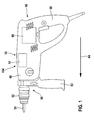
- FIG. 1 1 shows a drill and / or chisel hammer 10 according to the invention.
- the drill and / or chisel hammer 10 comprises a housing 48 and, in a front region 50, a tool holder 52 for receiving a tool 54.
- the drill bit comprises and / or chisel hammer 10 has a main handle 58 for operating the drill and / or chisel hammer 10 and for transmitting power from an operator to the drill and / or chisel hammer 10.
- the hammer and / or chisel hammer 10 is provided with a detachable auxiliary handle 62 executed.
- the auxiliary handle 62 can be detachably fastened to the drill and / or chisel hammer 10 via a latching connection or other connections that appear reasonable to the person skilled in the art.
- the auxiliary handle 62 is arranged to guide the drill and / or chisel hammer 10 by the operator in the vicinity of the tool holder 52 on the drill and / or chisel hammer 10.
- a main extension direction 64 of the rotary and / or hammer drill 10 extends from the main handle 58 in the direction of the tool holder 52.
- the hammer and / or chisel hammer 10 comprises a percussion device 104, which comprises a catcher unit 12 and a percussion unit 14.
- the drill and / or chisel hammer 10 has a drive unit 60.
- the drive torque of the drive unit 60 is transmitted via a non-illustrated transmission device of the drill and / or chisel hammer 10 for generating the impact pulse to the hammer mechanism unit 14 and for generating a rotational movement of the tool 54 via a guide member 66, which is designed here as a hammer tube to the tool holder 52 transmitted.
- the impact pulse of the percussion unit 14 is hereby generated in a manner known to those skilled in the art.
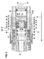
- FIG. 2 shows a sectional view of a first variant of the percussion unit 14 in an impact position.
- the drill and / or chisel hammer 10 comprises the catcher unit 12 and the percussion mechanism unit 14, which has at least one racket 16 and one striker pin 18.
- the catcher unit 12 is intended to hold the firing pin 18 in an idle region 20.
- the contact between the racket 16 and the firing pin 18 is prevented in an idling position, since the racket 16 and the firing pin 18 are arranged axially spaced along the main extension direction 64 (see. FIG. 3 ).
- the racket 16 and the firing pin 18 are mounted axially one behind the other along the main extension direction 64 of the drill and / or chisel hammer 10 in the guide element 66.
- the beater 16 and the firing pin 18 transmit in its impact position the impact pulse of the percussion unit 14 along a pulse transmission direction 24, which is parallel to the main extension direction 64, to the tool 54 located in the tool holder 52.
- the catcher unit 12 is disposed along the momentum transfer direction 24 in the percussion unit 14 in a region 70 which extends axially along the momentum transfer direction 24 and at least by a maximum extent of the striker 16 extending in a radial direction 46 of the catcher unit 12, and maximum extension of the firing pin 18, which also extends in the radial direction 46 of the catcher unit 12, is limited in an axial direction of the guide member 66.
- the catcher unit 12 comprises a damping element 32, two discs 76, 84 and a retaining ring 92. From the perspective of the impact position of the racket 16 along the pulse transmission direction 24 of the retaining ring 92 is arranged after the racket 16 6.
- the circlip 92 is held in this case in a groove which extends in a circumferential direction 94 of the guide member 66, wherein the retaining ring 92 serves as an axial securing the catcher unit 12 in the guide member 66 against the pulse transmission direction 24.
- the disc 76 On the retaining ring 92 is supported against the impulse transmission direction 24, the disc 76 from.
- the disc 76 is arranged in direct contact with the damping element 32, which has at least one inner contour 34 which is formed as a latching contour 36.
- the latching contour 36 has a latching recess 38, which is provided to receive at least one holding region 40 of the racket 16.
- the latching contour 36 or latching recess 38 merges in the direction of the racket 16 into a convex area 100 and in the direction of the firing pin 18 into a convex area 26 of the damping element 32 or catcher unit 12. Furthermore, the damping element 32 abuts along the pulse transmission direction 24 on the disc 84, thus the disc 84 along the pulse transmission direction 24 after the damping element 32 in stored the guide member 66. The disk 84 in turn rests against a shoulder 96 of the guide element 66. The shoulder 96 runs along the circumferential direction 94 of the guide element 66 and serves as an axial securing of the catcher unit 12 in the guide element 66 along the pulse transmission direction 24.
- the racket 16 and the firing pin 18 are brought by means of a pressing of the drill and / or chisel hammer 10 by an operator to a surface to be machined in its striking position.
- the tool 54 is displaced axially in the tool holder 52 counter to the main extension direction 64 and pushes the firing pin 18 from the idle region 20 into a striking region 22.
- the firing pin 18 slides along with a region 82 for impulse transmission along the convex region 26 of the catcher unit 12 and presses in this movement against the momentum transfer direction 24 the racket 16 from the recess 38 until the racket 16 has reached its stroke position.
- the area 82 of the firing pin 18 is moved by the movement of the tool 54 against the pulse transmission direction 24 through the latching recess 38 and along the convex portion 100 of the damping element 32 and the catcher unit 12 in the impact area 22.
- a striking surface 88 of the firing pin 18 protrudes against the impulse transmission direction 24 from the catcher unit 12 into the striking area 22.
- the firing pin 18 is at least partially guided by the catcher unit 12 in at least the striking position against the impulse transmission direction 24.
- the area 82 for impulse transmission of the firing pin 18 with the racket 16 is arranged on a side facing the racket 16 86 of the firing pin 18.
- the striking surface 88 of the firing pin 18 is arranged, whose surface normal vector points in the direction of the racket 16.
- the striking surface 88 of the firing pin 18 serves to impulse transmission between the racket 16 and the firing pin 18.
- the racket 16 also has a striking surface 90.
- the striking surface 90 of the racket 16 is arranged on the holding portion 40 of the racket 16 in the direction of the firing pin 18, wherein the surface normal vector of the striking surface 90 of the racket 16 in the direction of the firing pin 18 points.
- the drill and / or chisel hammer 10 has a damping unit 30, which is formed at least partially in one piece with the catcher unit 12.
- the damping unit 30 includes the damping element 32, which is at least provided to the guide member 66 and the drill and / or chisel hammer 10 in a striking position of the firing pin 18 of at least a return pulse of the firing pin 18 at least partially decoupled.
- the return pulse of the firing pin 18 by a stop portion 102 of the firing pin 18, the stopper portion 102 extends in the radial direction 46 over the region 82 for impulse transmission, guided by the disc 84 in the damping element 32.
- the disc 84 forms a stop for the stopper area 102 during a movement of the firing pin 18 against the pulse transmission direction 24.
- the damping element 32 is formed by a component made of resilient material.
- the guide element 66 and the components located in the immediate vicinity of the drill and / or chisel hammer 10 are at least partially decoupled from the return pulse of the firing pin 18 by the damping element 32.
- FIG. 3 shows a sectional view of the first variant of the percussion unit 14 in an idle position.
- the percussion unit 14 is brought by the operator by lifting a surface to be machined during operation of the drill and / or chisel hammer 10 from the impact position to the idle position.
- the tool 54 moves in the tool holder 52 along the main extension direction 64 of the drill and / or chisel hammer 10 in a percussion unit 14 facing away from the end position.
- a shock pulse transmission in the idle position on the tool 54 by the hammer mechanism unit 14 is thereby prevented.
- an idle control in particular a racket control
- the striker 16 and the striker 18 move to their idle positions after the tool 54 is already in the final position.
- the idle holes 68 are released in the guide member 66.
- the striker 18 is prevented by the catcher unit 12 from moving from its impact position to its idle position by moving against the momentum transfer direction 24.
- the catcher unit 12 limits the firing pin 18 in the idle position on one side Direction of the impact area 22.
- the firing pin 18 is in the idle position against the pulse transmission direction 24 with the region 82 for impulse transmission, which is also bead-like, at the convex portion 26 of the catcher unit 12, on a side facing the firing pin 18 side 28 of Catcher unit 12 is arranged.
- the convex portion 26 of the catcher unit 12 is disposed on the damping element 32 and thus serves as a stop of the firing pin 18 and the area 82 for impulse transmission in the idle position of the firing pin 18 in the direction of the impact area 22.
- a bead-edge area of the area 82 for impulse transmission which points in the direction of the racket 16, at the convex portion 26 of the catcher unit 12 at.
- a conically extending portion 72 in the guide member 66 as a stop for the firing pin 18 in the idle position of the firing pin 18.
- the catcher unit 12 is disposed between racket 16 and firing pin 18, that the firing pin 18 substantially free of play by means of the convex Area 26 of the catcher unit 12 and the conical portion 72 of the guide member 66 in the idle position of the firing pin 18 and in the idle region 20 is held.
- the racket 16 moves with the holding area 40 along the pulse transmission direction 24 into the damping element 32 until a side 74 of the racket 16 facing the catcher unit 12 strikes the pane 76.
- the holding portion 40 of the racket 16 has a smaller extent in the radial direction 46 of the catcher unit 12 than a maximum extension of the racket 16 in the radial direction 46 of the catcher unit 12 or the holding portion 40 of the racket 16 has a smaller outer diameter than the racket 16 itself, wherein the catcher unit 12 facing side 74 of the racket 16 is disposed in a region of the maximum extent of the racket 16.
- the disc 76 is arranged in direct contact with the damping element 32 and thus forms a component of the damping unit 30 and the catcher unit 12, respectively. Impact of the catcher unit 12 facing side 74 of the racket 16 on the disc 76 is transmitted from this to the damping element 32 and attenuated by the damping element 32.
- the damping member 32 is further provided to at least partially absorb the impact pulse of the striker 16 as the striker 16 moves to its idle position.
- the holding portion 40 of the racket 16 is held in the idle position of the racket 16 in the latching contour 36 and the latching recess 38 of the damping element 32, wherein the damping element 32 is at least partially formed by a catcher unit 12 of the racket 16.
- the catcher unit 12 is formed at least in one piece with the catcher unit 12 of the racket 16.
- the latching contour 36 or the latching recess 38 is shaped in such a way that the latching contour 36 or the latching recess 38 essentially corresponds in its shape to an outer contour 78 of the holding area 40 and thus forms a countercontour to the outer contour 78 of the holding area 40.
- the holding area 40 of the racket 16 is formed by a bead 80 which extends along the radial direction 46 of the catcher unit 12 in the direction of the guide element 66 and extends in the circumferential direction 94 of the guide element 66 about an end portion of the racket 16 facing the firing pin 18.
- the bead 80 is substantially completely received in the recess 38, whereby the racket 16 is caught securely.
- the latching recess 38 is arranged along an axial direction 42, which is aligned parallel to the pulse transmission direction 24, of the damping element 32 in a central region 44 of the damping element 32.
- the catcher unit 12 At least in the idling position of the racket 16 and the firing pin 18, the catcher unit 12 at least partially covers the racket 16 and at least partially the firing pin 18 in the radial direction 46 of the catcher unit 12, at least in the idle position.
- the holding area 40 or the bead 80 of FIG Bat 16 completely covered by the damping element 32.
- the region 82 for impulse transmission is partially covered by the damping element 32 and partially by the disc 84.
- FIG. 4 an alternative second variant of the percussion unit 14 is shown. Essentially, the same components, features and functions are always numbered the same. The following description is essentially limited to the differences from the first variant of the percussion unit 14 in the FIG. 3 , with respect to the same components, features and functions on the description of FIG. 3 can be referenced.
- a catcher unit 12 of the second variant of a percussion unit 14 is identical in construction to the first variant of the percussion unit 14.
- a racket 16 and a firing pin 18 are arranged in their idle position in a catcher unit 12 in direct contact with each other.
- a portion 82 of the firing pin 18 for impulse transmission has an additional neck 98 which extends axially against a portion 82 for impulse transmission 24.
- the additional neck 98 also extends opposite to the momentum transfer direction 24 via a bead-like Edge region of the region 82 for pulse transmission addition.
Abstract
Description
Die Erfindung geht aus von einem Bohr- und/oder Meißelhammer nach dem Oberbegriff des Anspruchs 1.The invention relates to a drill and / or chisel hammer according to the preamble of claim 1.
Es sind bereits Bohr- und/oder Meißelhämmer mit einer Fängereinheit und einer Schlagwerkeinheit, die einen Schläger und einen Schlagbolzen aufweist, bekannt. Die Fängereinheit ist dazu vorgesehen, den Schläger zu fangen.There are already known drill and / or chisel hammers with a catcher unit and a percussion unit, which has a racket and a striker. The catcher unit is intended to catch the bat.
Die Erfindung geht aus von einem Bohr- und/oder Meißelhammer mit einer Fängereinheit und einer Schlagwerkeinheit, die zumindest einen Schläger und einen Schlagbolzen aufweist.The invention relates to a drill and / or chisel hammer with a catcher unit and a percussion unit, which has at least one racket and a firing pin.
Es wird vorgeschlagen, dass die Fängereinheit dazu vorgesehen ist, den Schlagbolzen in einem Leerlaufbereich zu halten. In diesem Zusammenhang soll unter "vorgesehen" insbesondere speziell ausgestattet und/oder speziell ausgelegt verstanden werden. Der Begriff "Fängereinheit" soll hier insbesondere eine Einheit definieren, die zumindest ein Bauteil aufweist, das dazu vorgesehen ist, zumindest den Schlagbolzen und/oder den Schlagbolzen zusammen mit dem Schläger in einem Leerlaufbereich und/oder in einer Position, insbesondere in einer Leerlaufposition, zu fangen und/oder darin zu halten, insbesondere nahezu spielfrei in der Position zu halten, wobei im Leerlaufbereich und insbesondere in der Leerlaufposition eine Schlagimpulsübertragung des Schlagbolzens und/oder des Schlägers auf ein in einer Werkzeugaufnahme befindliches Werkzeug unterbunden ist. Unter der Bezeichnung "Schlagwerkeinheit" soll hier insbesondere eine Einheit verstanden werden, die zumindest ein Bauteil aufweist, das zu einer Erzeugung und/oder Übertragung eines Impulses, insbesondere eines axialen Schlagimpulses, auf ein Werkzeug vorgesehen ist. Ein solches Bauteil kann insbesondere ein Schlagbolzen, ein Schläger, ein Führungselement, wie insbesondere ein Hammerrohr und/oder ein Kolben, wie insbesondere ein Topfkolben und/oder weitere, dem Fachmann als sinnvoll erscheinende Bauteile sein. Unter dem Begriff "Leerlaufbereich" soll hier während einem Betrieb des Bohr- und/oder Meißelhammers insbesondere ein Bereich innerhalb der Schlagwerkeinheit, insbesondere innerhalb eines Führungselements zur Führung des Schlagbolzens und/oder des Schlägers, entlang einer Impulsübertragungsrichtung verstanden werden, in dem sich zumindest der Schlagbolzen und/oder der Schlagbolzen zusammen mit dem Schläger während einer Leerlaufposition befindet. Vorzugsweise ist das Führungselement insbesondere von einem rohr- bzw. zylinderförmigen Element gebildet, welches insbesondere dazu vorgesehen ist, den Schläger und/oder den Schlagbolzen axial entlang einer Impulsübertragungsrichtung der Schlagwerkeinheit zu führen. Das Führungselement kann zudem besonders vorteilhaft einstückig mit einem Hammerrohr ausgebildet sein und/oder es kann einstückig mit einem Kolben, wie z.B. einem Topfkolben ausgebildet sein. Unter der Bezeichnung "Leerlaufposition" soll hier während einem Betrieb des Bohr- und/oder Meißelhammers insbesondere eine Position zumindest des Schlagbolzens und/oder des Schlägers verstanden werden, in der die Schlagimpulsübertragung des Schlagbolzens und/oder des Schlägers auf ein in einer Werkzeugaufnahme befindliches Werkzeug unterbunden ist.It is proposed that the catcher unit is intended to keep the striker in an idle range. In this context, "intended" should be understood to mean in particular specially equipped and / or specially designed. The term "catcher unit" should in particular define a unit which has at least one component that is provided to at least the firing pin and / or the firing pin together with the racket in an idle area and / or in a position, in particular in an idle position, catch and / or to keep in it, in particular to keep almost free of play in the position, wherein in the idle range and in particular in the idle position a shock pulse transmission of the firing pin and / or the racket is prevented on a tool located in a tool holder tool. The term "percussion unit" is to be understood here in particular a unit which has at least one component which is provided for generating and / or transmitting a pulse, in particular an axial impact pulse, on a tool. Such a component may in particular be a firing pin, a racket, a guide element, such as in particular a hammer tube and / or a piston, in particular a pot piston and / or further components that appear appropriate to the person skilled in the art. The term "idle range" should be understood here during operation of the drill and / or chisel hammer in particular a region within the percussion unit, in particular within a guide element for guiding the firing pin and / or the racket along a pulse transmission direction in which at least the Firing pin and / or the firing pin is located together with the racket during an idle position. Preferably, the guide element is in particular formed by a tubular or cylindrical element, which is in particular provided to guide the racket and / or the firing pin axially along a pulse transmission direction of the percussion unit. The guide member may also be particularly advantageously formed integrally with a hammer tube and / or it may be integrally formed with a piston, such as a pot piston. The term "idle position" should be understood here during operation of the drill and / or chisel hammer in particular a position at least of the firing pin and / or the racket, in which the impact pulse transmission of the firing pin and / or the racket on a befindliches in a tool holder tool is prevented.
Durch die erfindungsgemäße Ausgestaltung des Bohr- und/oder Meißelhammers kann vorteilhafterweise eine hohe Bedienerfreundlichkeit erreicht werden. Durch das Halten des Schlagbolzens in dem Leerlaufbereich kann vorteilhaft ein für den Bediener als unangenehm wahrgenommenes Geräusch zumindest reduziert und/oder verhindert werden, indem eine Impulsübertragung des Schlagbolzens auf ein weiteres Bauteil in dem Leerlaufbereich, insbesondere nach einem Abheben des Bohr- und/oder Meißelhammers durch den Bediener von einer zu bearbeitenden Oberfläche, verhindert werden kann und damit eine insbesondere nahezu spielfreie Positionierung des Schlagbolzens in der Leerlaufposition erreicht werden kann. Ferner können durch das Halten des Schlagbolzens Bauteile, die in dem Leerlaufbereich in Kontakt mit dem Schlagbolzen stehen, vorteilhaft geschont werden, da eine Bewegung des Schlagbolzens zumindest eingeschränkt und/oder verhindert werden kann und somit auch Schläge des Schlagbolzens auf die Bauteile vorteilhaft verhindert werden können.The inventive design of the drill and / or chisel hammer advantageously a high level of user-friendliness can be achieved. By holding the firing pin in the idle region advantageously a perceived as unpleasant for the operator noise can be at least reduced and / or prevented by an impulse transmission of the firing pin on another component in the no-load area, in particular after a lifting of the drill and / or chisel by the operator of a surface to be machined, can be prevented and thus a particular almost backlash-free positioning of the firing pin in the idle position can be achieved. Further, by holding the firing pin components that are in contact with the firing pin in the idle range, can be advantageously spared because movement of the firing pin can be at least limited and / or prevented and thus also blows of the firing pin can be advantageously prevented on the components ,
Ferner wird vorgeschlagen, dass die Fängereinheit den Schlagbolzen in zumindest einer Betriebsposition einseitig in Richtung eines Schlagbereichs begrenzt. Unter dem Begriff "Betriebsposition" soll hier insbesondere eine Position der Schlagwerkeinheit des Bohr- und/oder Meißelhammers während des Betriebs verstanden werden, in welcher ein Bediener den Bohr- und/oder Meißelhammer an eine zu bearbeitende Oberfläche andrückt, von dieser abhebt und/oder in einer Stellung hält, in welcher der Bohr- und/oder Meißelhammer von der zu bearbeitenden Oberfläche abgehoben ist, wie insbesondere eine Leerlaufposition und/oder eine Schlagposition, in der die Schlagimpulsübertragung des Schlagbolzens und/oder des Schlägers auf ein in einer Werkzeugaufnahme befindliches Werkzeug ermöglicht ist. Vorzugsweise soll hier unter der Betriebsposition die Leerlaufposition des Schlagbolzens und/oder des Schlägers verstanden werden. Die Bezeichnung "Schlagbereich" soll hier während des Betriebs des Bohr- und/oder Meißelhammers insbesondere einen Bereich innerhalb der Schlagwerkeinheit entlang einer Impulsübertragungsrichtung definieren, insbesondere innerhalb eines Führungselements zur Führung des Schlägers und/oder des Schlagbolzens, in dem sich zumindest der Schlagbolzen und/oder der Schläger während der Schlagimpulsübertragung befindet und in dem insbesondere in der Schlagposition eine Schlagimpulsübertragung des Schlägers auf den Schlagbolzen in einem Betrieb des Bohr- und/oder Meißelhammers erfolgt. Unter dem Begriff "einseitig begrenzt" soll hier insbesondere eine Begrenzung einer Bewegung des Schlagbolzens entgegen der Impulsübertragungsrichtung verstanden werden. Hierdurch kann vorteilhaft erreicht werden, dass der Schlagbolzen sicher im Leerlaufbereich gehalten wird und somit eine kompakte Fängereinheit zur Verfügung gestellt werden kann. Besonders vorteilhaft ist die Fängereinheit hierbei von einem Anschlag für den Schlagbolzen gebildet, wodurch weitere Bauteile, Bauraum, Montageaufwand und Kosten eingespart werden können.It is also proposed that the catcher unit limits the firing pin in at least one operating position on one side in the direction of a striking area. The term "operating position" should be understood here in particular a position of the percussion unit of the drill and / or chisel hammer during operation, in which an operator presses the drill and / or chisel to a surface to be machined, lifts from this and / or holds in a position in which the drill and / or chisel is lifted from the surface to be machined, such as in particular an idle position and / or an impact position in which the impact pulse transmission of the firing pin and / or the racket on a befindliches in a tool holder tool is possible. Preferably, the idle position of the firing pin and / or the racket should be understood here by the operating position. The term "impact area" should in particular define an area within the percussion unit along a pulse transmission direction during operation of the drill and / or hammer, in particular within a guide element for guiding the racket and / or the striker, in which at least the striker and / or or the racket is located during the impact pulse transmission and in which in particular in the striking position a shock pulse transmission of the racket on the firing pin in an operation of the drill and / or chisel hammer takes place. The term "unilaterally limited" is to be understood here as meaning in particular a limitation of a movement of the firing pin counter to the momentum transfer direction. This can advantageously be achieved that the firing pin is held securely in the idle range and thus a compact catcher unit can be provided. Particularly advantageously, the catcher unit is formed here by a stop for the firing pin, whereby further components, space, installation costs and costs can be saved.
Vorzugsweise liegt der Schlagbolzen in zumindest der Betriebsposition entgegen der Impulsübertragungsrichtung an einem konvexen Bereich der Fängereinheit an, der an einer dem Schlagbolzen zugewandten Seite der Fängereinheit angeordnet ist. Die Impulsübertragungsrichtung erstreckt sich hierbei im Wesentlichen parallel zu einer Haupterstreckungsrichtung des Bohr- und/oder Meißelhammers von dem Schläger über den Schlagbolzen in Richtung eines Werkzeugs. Unter dem Begriff "im Wesentlichen parallel" soll hier insbesondere eine Richtung verstanden werden, die gegenüber einer Bezugsrichtung eine Abweichung insbesondere kleiner als 8°, vorteilhaft kleiner als 5° und besonders vorteilhaft kleiner als 2° aufweist. Unter einem "konvexen Bereich" soll hierbei insbesondere ein Bereich mit einer konvexen, dem Schlagbolzen zugewandten, insbesondere an dem Schlagbolzen in zumindest einer Position des Schlagbolzens, insbesondere der Leerlaufposition, anliegenden Oberfläche und/oder eine entlang einer radialen Richtung des Schlagbolzens und/oder eines Führungselements im Wesentlichen nach innen gewandte, konvexe Oberfläche der Fängereinheit verstanden werden. Grundsätzlich kann der konvexe Bereich auch eine andere, dem Fachmann als sinnvoll erscheinende Form aufweisen, wie z.B. rampenförmig. Durch eine derartige Ausgestaltung der Erfindung kann eine konstruktiv einfache Anlagefläche für den Schlagbolzen, insbesondere in der Leerlaufposition, geschaffen werden und zugleich kann erreicht werden, dass der Schlagbolzen bei einem Übergang in eine andere Betriebsposition, insbesondere in die Schlagposition, vorteilhaft, insbesondere verschleißreduziert an dem konvexen Bereich entlang gleiten kann.Preferably, in at least the operating position, the firing pin bears against a convex region of the catcher unit opposite to the impulse transmission direction, which is arranged on a side of the catcher unit facing the firing pin. The pulse transmission direction here extends substantially parallel to a main direction of extension of the rotary and / or chisel hammer from the racket via the firing pin in the direction of a tool. The term "essentially parallel" is to be understood here in particular as meaning a direction which, relative to a reference direction, has a deviation, in particular less than 8 °, advantageously less than 5 ° and particularly advantageously less than 2 °. In this context, a "convex region" is intended to mean, in particular, an area with a convex surface facing the firing pin, in particular on the firing pin in at least one position of the firing pin, in particular the idling position, and / or along a radial direction of the firing pin and / or a guide element substantially inwardly facing, convex surface of the catcher unit can be understood. In principle, the convex region can also have another shape that appears appropriate to the person skilled in the art, such as, for example, ramp-shaped. By such an embodiment of the invention, a structurally simple contact surface for the firing pin, in particular in the idle position, created and at the same time can be achieved that the firing pin in a transition to another operating position, in particular in the impact position, advantageous, in particular wear-reduced on the can slide along convex area.
In einer weiteren Ausgestaltung der Erfindung wird eine Dämpfungseinheit vorgeschlagen, die zumindest teilweise einstückig mit der Fängereinheit ausgebildet ist. Unter einer "Dämpfungseinheit" soll hier insbesondere eine Einheit verstanden werden, die zumindest ein Bauteil, insbesondere ein Dämpfungselement, umfasst, das bevorzugt dazu vorgesehen ist, eine Übertragung eines Schlagimpulses des Schlagbolzens und/oder des Schlägers auf ein Gehäuse und/oder auf zumindest ein dem Gehäuse zugeordnetes Bauteil zu reduzieren. Die Dämpfungseinheit dient hierbei vorteilhaft zumindest teilweise zu einer Schwingungsisolierung und/oder Schwingungsdämpfung zwischen dem Schlagbolzen und/oder dem Schläger und/oder dem Gehäuse und/oder dem zumindest einem, dem Gehäuse zugeordneten Bauteil. Des Weiteren soll unter "einstückig" insbesondere einteilig und/oder aus einem Guss gebildet und/oder als ein Bauteil ausgebildet verstanden werden. Vorzugsweise ist die Fängereinheit einstückig mit einem Dämpfungselement der Dämpfungseinheit ausgebildet. Es können hierdurch vorteilhaft Bauteile eingespart werden und die Kosten des Bohr- und/oder Meißelhammers können gering gehalten werden.In a further embodiment of the invention, a damping unit is proposed, which is at least partially formed integrally with the catcher unit. A "damping unit" is to be understood here in particular as a unit which comprises at least one component, in particular a damping element, which is preferably provided for transmitting a shock pulse of the firing pin and / or the racket to a housing and / or at least one reduce the component associated with the housing. The damping unit advantageously serves at least partially for vibration isolation and / or vibration damping between the firing pin and / or the racket and / or the housing and / or the at least one component assigned to the housing. Furthermore, the term "integral" is to be understood to mean, in particular, one-piece and / or cast and / or formed as a component. Preferably, the catcher unit is formed integrally with a damping element of the damping unit. It can be advantageously saved components and the cost of the drill and / or chisel hammer can be kept low.
Des Weiteren wird vorgeschlagen, dass die Dämpfungseinheit ein Dämpfungselement umfasst, das zumindest dazu vorgesehen ist, ein Bauteil von zumindest einem Rückschlagimpuls des Schlagbolzens zumindest teilweise zu entkoppeln. Unter einem "Rückschlagimpuls" soll hier insbesondere ein Schlagimpuls des Schlagbolzens verstanden werden, welcher bei der Impulsübertragung des Schlagbolzens auf das Werkzeug von dem Werkzeug auf den Schlagbolzen übertragen wird und entgegen der Impulsübertragungsrichtung gerichtet ist. Vorzugsweise ist das Dämpfungselement aus einem federelastischen Material gebildet, wie aus einem gummiartigen Material und/oder aus einem Federstahl. Das Dämpfungselement kann von mehreren Bauteilen gebildet sein, wie vorzugsweise von zwei O-Ringen, die in unmittelbarer Nähe zueinander angeordnet sind und vorzugsweise in direktem Kontakt miteinander angeordnet sind, oder das Dämpfungselement kann besonders bevorzugt von einem einzelnen Bauteil gebildet sein. Es sind auch andere, dem Fachmann als sinnvoll erscheinende Variationen des Dämpfungselements möglich. Durch das Dämpfungselement können die Bauteile, welche sich in unmittelbarer Nähe des Schlagbolzens befinden, vorteilhaft geschont werden, insbesondere kann eine Beanspruchung und/oder ein Verschleiß der Bauteile reduziert werden. Hierdurch kann eine lange Lebensdauer der Bauteile und somit auch des Bohr- und/oder Meißelhammers erreicht werden.Furthermore, it is proposed that the damping unit comprises a damping element which is at least provided to at least partially decouple a component from at least one return pulse of the firing pin. A "kickback impulse" is to be understood here in particular as a percussion impulse of the firing pin, which is transmitted during the impulse transmission of the firing pin to the tool from the tool to the firing pin and is directed counter to the impulse transmission direction. Preferably, the damping element is formed of a resilient material, such as a rubber-like material and / or a spring steel. The damping element may be formed by a plurality of components, such as preferably two O-rings, which are arranged in close proximity to each other and are preferably arranged in direct contact with each other, or the damping element may be particularly preferably formed by a single component. There are others, the expert as reasonable appearing variations of the damping element possible. By the damping element, the components which are located in the immediate vicinity of the firing pin can be advantageously spared, in particular, a stress and / or wear of the components can be reduced. In this way, a long service life of the components and thus also of the drill and / or chisel hammer can be achieved.
Vorzugsweise umfasst die Dämpfungseinheit ein Dämpfungselement, das dazu vorgesehen ist, zumindest einen Schlagimpuls des Schlägers zumindest teilweise zu absorbieren. Es kann vorteilhaft eine zumindest teilweise Entkopplung des Schlagbolzens von einem Schlagimpuls des Schlägers, insbesondere in der Leerlaufposition, erreicht werden. Zudem können mittels einer derartigen Ausgestaltung des Dämpfungselements vorteilhaft weitere Bauteile eingespart werden. Des Weiteren kann durch eine geeignete Wahl des Materials, insbesondere federelastische Materialien, wie z.B. Elastomere, das Dämpfungselement an eine bestimmte Arbeitsbedingung des Bohr- und/oder Meißelhammers vorteilhaft angepasst werden.Preferably, the damping unit comprises a damping element which is provided to at least partially absorb at least one impact pulse of the racket. Advantageously, at least partial decoupling of the firing pin from a percussion impulse of the racket, in particular in the idling position, can be achieved. In addition, advantageously further components can be saved by means of such a design of the damping element. Furthermore, by a suitable choice of material, in particular resilient materials, e.g. Elastomers, the damping element are adapted to a particular working condition of the drill and / or chisel advantageous.
Die Fängereinheit des Schlagbolzens kann grundsätzlich getrennt von einer Fängereinheit des Schlägers ausgebildet sein. Vorzugsweise ist die Fängereinheit des Schlagbolzens zumindest teilweise einstückig mit der Fängereinheit des Schlägers ausgebildet. Durch die einstückige Ausbildung der Fängereinheit kann vorteilhaft weiterer Bauraum konstruktiv einfach eingespart werden und zudem können Kosten eingespart werden.The catcher unit of the firing pin can basically be formed separately from a catcher unit of the racket. Preferably, the catcher unit of the firing pin is at least partially formed integrally with the catcher unit of the racket. The one-piece design of the catcher unit advantageously further space can be saved structurally simple and also costs can be saved.
Ferner wird vorgeschlagen, dass die Fängereinheit zumindest eine Innenkontur aufweist, die als Rastkontur ausgebildet ist. Unter dem Begriff "Innenkontur" soll hier insbesondere eine Kontur zumindest eines Bauteils, vorzugsweise der Fängereinheit, insbesondere des Dämpfungselements, verstanden werden, die entlang der Impulsübertragungsrichtung an einem inneren Querschnitt des Bauteils verläuft, wobei der innere Querschnitt durch einen Durchbruch im Bauteil in Richtung der Impulsübertragungsrichtung gebildet ist und in einer Ebene liegt, die sich entlang einer Impulsübertragungsrichtung erstreckt. Des Weiteren soll unter einer "Rastkontur" insbesondere eine Kontur verstanden werden, die zu einer Rastverbindung vorzugsweise mit dem Schläger und/oder dem Schlagbolzen und/oder einem weiteren Bauteil vorgesehen ist. Hierdurch kann die Fängereinheit kompakt gehalten werden und zudem kann eine sichere Positionierung des Schlägers und/oder des Schlagbolzens in der Fängereinheit erreicht werden. Ferner kann durch die Anpassung der Kontur an eine bestimmte Arbeitsbedingung des Bohr- und/oder Meißelhammers vorteilhaft eine für die Arbeitsbedingung bevorzugte Haltekraft der Fängereinheit erreicht werden.It is also proposed that the catcher unit has at least one inner contour, which is designed as a latching contour. The term "inner contour" is to be understood here in particular a contour of at least one component, preferably the catcher unit, in particular of the damping element, which runs along the pulse transmission direction at an inner cross section of the component, wherein the inner cross section through an opening in the component in the direction of Pulse transmission direction is formed and lies in a plane which extends along a pulse transmission direction. Furthermore, a "detent contour" is to be understood as meaning, in particular, a contour which is provided for a latching connection, preferably with the racket and / or the firing pin and / or a further component. In this way, the catcher unit can be kept compact and also a secure positioning of the racket and / or the firing pin can be achieved in the catcher unit. Furthermore, by adapting the contour to a specific working condition of the rotary and / or chisel hammer, a holding force of the catcher unit which is preferred for the working condition can advantageously be achieved.
Vorzugsweise weist die Rastkontur zumindest eine Rastausnehmung auf, die dazu vorgesehen ist, zumindest einen Haltebereich des Schlägers aufzunehmen. Unter einer "Rastausnehmung" soll hier insbesondere eine Ausnehmung verstanden werden, die zumindest dazu vorgesehen ist, zumindest teilweise ein Bauteil in einer Position aufzunehmen und dieses Bauteil in dieser Position zu halten und/oder zu fixieren. Unter einer "Ausnehmung" soll in diesem Zusammenhang insbesondere eine Vertiefung und/oder eine Materialaussparung in der Fängereinheit verstanden werden. Die Rastausnehmung ist bevorzugt an einer in einer radialen Richtung der Fängereinheit nach innen weisenden Oberfläche angeordnet. Hierbei verläuft die radiale Richtung der Fängereinheit im Wesentlichen senkrecht zur Impulsübertragungsrichtung. Der Ausdruck "Haltebereich" definiert hier insbesondere einen dem Schlagbolzen zugewandten Bereich des Schlägers, insbesondere einen Bereich, welcher einen geringeren Querschnitt in radialer Richtung der Fängereinheit bzw. einen geringeren Außendurchmesser aufweist als eine maximale Ausdehnung in radialer Richtung der Fängereinheit. Der Haltebereich ist bevorzugt derart ausgebildet, dass er im Wesentlichen eine Gegenkontur zur Rastkontur der Fängereinheit bildet. Hierdurch kann die Rastkontur zur Sicherung des Schlägers und/oder des Schlagbolzens konstruktiv einfach erreicht werden.Preferably, the latching contour has at least one latching recess which is provided to receive at least one holding region of the racket. A "detent recess" is to be understood here in particular as a recess which is at least provided to at least partially receive a component in one position and to hold and / or fix this component in this position. A "recess" is to be understood in this context, in particular a recess and / or a material recess in the catcher unit. The latching recess is preferably arranged on a surface facing inward in a radial direction of the catcher unit. Here, the radial direction of the catcher unit is substantially perpendicular to the pulse transmission direction. The term "holding area" here defines in particular a region of the racket facing the firing pin, in particular a portion which has a smaller cross-section in the radial direction of the catcher unit or a smaller outer diameter than a maximum extent in the radial direction of the catcher unit. The holding region is preferably designed such that it essentially forms a counter contour to the catch contour of the catcher unit. In this way, the locking contour for securing the racket and / or the firing pin can be achieved structurally simple.
In einer erfindungsgemäßen Ausgestaltung ist die Rastausnehmung an ein Dämpfungselement angeformt. Hierdurch können zusätzliche Bauteile zur Aufnahme des Schlägers entfallen und die Kosten des Bohr- und/oder Meißelhammers können vorteilhaft gering gehalten werden.In an embodiment according to the invention, the latching recess is formed on a damping element. As a result, additional components for receiving the racket can be omitted and the cost of the drill and / or chisel hammer can be advantageously kept low.
Vorzugsweise ist die Rastausnehmung entlang einer axialen Richtung der Fängereinheit in einem mittleren Bereich der Fängereinheit angeordnet. Hierbei erstreckt sich die axiale Richtung der Fängereinheit im Wesentlichen parallel zur Impulsübertragungsrichtung. Es kann hierdurch eine vorteilhafte Krafteinleitung in die Fängereinheit erreicht werden, da sich eingeleitete Kräfte im Wesentlichen auf beide Seiten der Fängereinheit gleichmäßig verteilen können.Preferably, the catch recess is arranged along an axial direction of the catcher unit in a central region of the catcher unit. In this case, the axial direction of the catcher unit extends substantially parallel to the pulse transmission direction. As a result, an advantageous introduction of force into the catcher unit can be achieved since forces introduced can be distributed uniformly substantially on both sides of the catcher unit.
Des Weiteren wird vorgeschlagen, dass die Fängereinheit zumindest in einer Betriebsposition entlang einer Impulsübertragungsrichtung zumindest teilweise den Schläger und zumindest teilweise den Schlagbolzen in einer radialen Richtung der Fängereinheit überdeckt. Vorzugsweise ist die Betriebsposition von der Leerlaufposition des Schlagbolzens und/oder des Schlägers gebildet. Unter "zumindest teilweise überdeckt" soll hinsichtlich einer Überdeckung des Schlagbolzens insbesondere eine Überdeckung eines Bereichs des Schlagbolzens verstanden werden, in dem eine Schlagfläche angeordnet ist. Bezüglich der Überdeckung des Schlägers soll hierbei insbesondere der Haltebereich und ein Bereich verstanden werden, in dem eine Schlagfläche angeordnet ist. Unter dem Begriff "Schlagfläche" soll hier insbesondere eine Fläche des Schlagbolzens und/oder des Schlägers verstanden werden, die in einer Ebene angeordnet ist, welche sich in radialer Richtung der Fängereinheit erstreckt, wobei ein Flächennormalenvektor der Schlagfläche im Wesentlichen entlang der Impulsübertragungsrichtung verläuft. Vorzugsweise ist die Schlagfläche dazu vorgesehen, Schlagimpulse aufzunehmen bzw. zu übertragen. Durch eine derartige Ausgestaltung kann die Fängereinheit kompakt gehalten werden und zudem eine vorteilhafte Sicherung des Schlägers und/oder des Schlagbolzens in der Leerlaufposition erreicht werden.Furthermore, it is proposed that, at least in one operating position along a pulse transmission direction, the catcher unit at least partially covers the racket and at least partially the firing pin in a radial direction of the catcher unit. Preferably, the operating position of the idle position of the firing pin and / or the racket is formed. By "at least partially covered" should be understood in terms of overlap of the firing pin in particular a coverage of a portion of the firing pin, in which a striking surface is arranged. With regard to the overlap of the racket, the holding area and an area in which a striking surface is arranged should be understood here in particular. Under The term "impact surface" is to be understood here in particular as a surface of the firing pin and / or of the racket, which is arranged in a plane which extends in the radial direction of the catcher unit, wherein a surface normal vector of the striking surface runs essentially along the impulse transmission direction. Preferably, the striking surface is intended to receive or transmit impact pulses. By such a configuration, the catcher unit can be kept compact and also an advantageous securing of the racket and / or the firing pin in the idle position can be achieved.
In einer weiteren Ausgestaltung der Erfindung ist der Schlagbolzen in zumindest einer Betriebsposition entgegen einer Impulsübertragungsrichtung zumindest teilweise durch die Fängereinheit hindurch geführt. Vorzugsweise ist die Betriebsposition von der Schlagposition des Schlagbolzens und/oder des Schlägers gebildet. Unter dem Begriff "teilweise hindurch geführt" soll hier insbesondere verstanden werden, dass zumindest ein Bereich des Schlagbolzens mit der Schlagfläche entgegen der Impulsübertragungsrichtung durch die Fängereinheit, insbesondere durch das Dämpfungselement, hindurch geführt ist. Es kann vorteilhaft erreicht werden, dass der Schlagbolzen sicher in seiner Leerlaufposition gehalten werden kann. Der Schlagbolzen kann somit nur in einen Schlagbereich bewegt werden, wenn eine bestimmte Kraft überwunden wird, um durch die Fängereinheit hindurch geführt zu werden.In a further embodiment of the invention, the firing pin is guided in at least one operating position against a pulse transmission direction at least partially through the catcher unit. Preferably, the operating position of the impact position of the firing pin and / or the racket is formed. The term "partially passed through" is to be understood here in particular as meaning that at least one region of the firing pin with the impact surface is guided through the catcher unit, in particular through the damping element, counter to the impulse transmission direction. It can be advantageously achieved that the firing pin can be securely held in its idle position. The firing pin can thus only be moved into a striking area when a certain force is overcome in order to be guided through the catcher unit.
Weitere Vorteile ergeben sich aus der folgenden Zeichnungsbeschreibung. In der Zeichnung ist ein Ausführungsbeispiel der Erfindung dargestellt. Die Zeichnung, die Beschreibung und die Ansprüche enthalten zahlreiche Merkmale in Kombination. Der Fachmann wird die Merkmale zweckmäßigerweise auch einzeln betrachten und zu sinnvollen weiteren Kombinationen zusammenfassen.Further advantages emerge from the following description of the drawing. In the drawing, an embodiment of the invention is shown. The drawing, the description and the claims contain numerous features in combination. The person skilled in the art will expediently also consider the features individually and combine them into meaningful further combinations.
- Fig. 1Fig. 1
- einen erfindungsgemäßen Bohr- und/oder Meißelhammer mit einer Schlagwerkeinheit,a drill and / or chisel hammer according to the invention with a percussion unit,
- Fig. 2Fig. 2
- eine Schnittdarstellung einer ersten Variante der Schlagwerkeinheit in einer Schlagposition,a sectional view of a first variant of the percussion unit in an impact position,
- Fig. 3Fig. 3
- eine Schnittdarstellung der ersten Variante der Schlagwerkeinheit in einer Leerlaufposition unda sectional view of the first variant of the percussion unit in an idle position and
- Fig. 4Fig. 4
- eine Schnittdarstellung einer zweiten Variante der Schlagwerkeinheit in einer Leerlaufposition.a sectional view of a second variant of the percussion unit in an idle position.
Bei der ersten Variante der Schlagwerkeinheit 14 ist der Kontakt zwischen dem Schläger 16 und dem Schlagbolzen 18 in einer Leerlaufposition verhindert, da der Schläger 16 und der Schlagbolzen 18 axial entlang der Haupterstreckungsrichtung 64 voneinander beabstandet angeordnet sind (vgl.
Die Fängereinheit 12 ist entlang der Impulsübertragungsrichtung 24 in der Schlagwerkeinheit 14 in einem Bereich 70 angeordnet, der sich axial entlang der Impulsübertragungsrichtung 24 erstreckt und zumindest durch eine maximale Ausdehnung des Schlägers 16, die sich in eine radiale Richtung 46 der Fängereinheit 12 erstreckt, und einer maximalen Ausdehnung des Schlagbolzens 18, die sich ebenfalls in der radialen Richtung 46 der Fängereinheit 12 erstreckt, in einer axialen Richtung des Führungselements 66 begrenzt ist. Die Fängereinheit 12 umfasst ein Dämpfungselement 32, zwei Scheiben 76, 84 und einen Sicherungsring 92. Aus Sicht der Schlagposition des Schlägers 16 entlang der Impulsübertragungsrichtung 24 ist der Sicherungsring 92 nach dem Schläger 16 6 angeordnet. Der Sicherungsring 92 wird hierbei in einer Nut gehalten, welche in einer Umfangsrichtung 94 des Führungselements 66 verläuft, wobei der Sicherungsring 92 als axiale Sicherung der Fängereinheit 12 im Führungselement 66 entgegen der Impulsübertragungsrichtung 24 dient. An den Sicherungsring 92 stützt sich entgegen der Impulsübertragungsrichtung 24 die Scheibe 76 ab. Die Scheibe 76 ist in direktem Kontakt mit dem Dämpfungselement 32 angeordnet, welches zumindest eine Innenkontur 34 aufweist, die als eine Rastkontur 36 ausgebildet ist. Die Rastkontur 36 weist eine Rastausnehmung 38 auf, die dazu vorgesehen ist, zumindest einen Haltebereich 40 des Schlägers 16 aufzunehmen. Die Rastkontur 36 bzw. Rastausnehmung 38 geht in Richtung des Schlägers 16 in einen konvexen Bereich 100 und in Richtung des Schlagbolzens 18 in einen konvexen Bereich 26 des Dämpfungselements 32 bzw. der Fängereinheit 12 über. Des Weiteren liegt das Dämpfungselement 32 entlang der Impulsübertragungsrichtung 24 an der Scheibe 84 an, somit ist die Scheibe 84 entlang der Impulsübertragungsrichtung 24 nach dem Dämpfungselement 32 in dem Führungselement 66 gelagert. Die Scheibe 84 liegt ihrerseits an einer Schulter 96 des Führungselements 66 an. Die Schulter 96 verläuft entlang der Umfangrichtung 94 des Führungselements 66 und dient als axiale Sicherung der Fängereinheit 12 im Führungselement 66 entlang der Impulsübertragungsrichtung 24.The
Der Schläger 16 und der Schlagbolzen 18 werden mittels eines Andrückens des Bohr- und/oder Meißelhammers 10 durch einen Bediener an eine zu bearbeitende Oberfläche in ihre Schlagposition gebracht. Hierbei wird das Werkzeug 54 entgegen der Haupterstreckungsrichtung 64 axial in der Werkzeugaufnahme 52 verschoben und drückt den Schlagbolzen 18 aus dem Leerlaufbereich 20 in einen Schlagbereich 22. Der Schlagbolzen 18 gleitet mit einem Bereich 82 zur Impulsübertragung an dem konvexen Bereich 26 der Fängereinheit 12 entlang und drückt bei dieser Bewegung entgegen der Impulsübertragungsrichtung 24 den Schläger 16 aus der Rastausnehmung 38 bis der Schläger 16 seine Schlagposition erreicht hat. Ferner wird der Bereich 82 des Schlagbolzens 18 durch die Bewegung des Werkzeugs 54 entgegen der Impulsübertragungsrichtung 24 durch die Rastausnehmung 38 und entlang des konvexen Bereichs 100 des Dämpfungselements 32 bzw. der Fängereinheit 12 in den Schlagbereich 22 bewegt. In der Schlagposition des Schlagbolzens 18 ragt eine Schlagfläche 88 des Schlagbolzens 18 entgegen der Impulsübertragungsrichtung 24 aus der Fängereinheit 12 in den Schlagbereich 22. Somit ist der Schlagbolzen 18 in zumindest der Schlagposition entgegen der Impulsübertragungsrichtung 24 zumindest teilweise durch die Fängereinheit 12 hindurch geführt.The
Der Bereich 82 zur Impulsübertragung des Schlagbolzens 18 mit dem Schläger 16 ist an einer dem Schläger 16 zugewandten Seite 86 des Schlagbolzens 18 angeordnet. An dem Bereich 82 zur Impulsübertragung ist die Schlagfläche 88 des Schlagbolzens 18 angeordnet, dessen Flächennormalenvektor in Richtung des Schlägers 16 weist. Die Schlagfläche 88 des Schlagbolzens 18 dient zur Impulsübertragung zwischen dem Schläger 16 und dem Schlagbolzen 18. Hierbei weist der Schläger 16 ebenfalls eine Schlagfläche 90 auf. Die Schlagfläche 90 des Schlägers 16 ist an dem Haltebereich 40 des Schlägers 16 in Richtung des Schlagbolzens 18 angeordnet, wobei der Flächennormalenvektor der Schlagfläche 90 des Schlägers 16 in Richtung des Schlagbolzens 18 weist.The
Des Weiteren weist der Bohr- und/oder Meißelhammer 10 eine Dämpfungseinheit 30 auf, die zumindest teilweise einstückig mit der Fängereinheit 12 ausgebildet ist. Die Dämpfungseinheit 30 umfasst das Dämpfungselement 32, das zumindest dazu vorgesehen ist, das Führungselement 66 bzw. den Bohr- und/oder Meißelhammer 10 in einer Schlagposition des Schlagbolzens 18 von zumindest einem Rückschlagimpuls des Schlagbolzens 18 zumindest teilweise zu entkoppeln. Hierbei wird der Rückschlagimpuls des Schlagbolzens 18 durch einen Anschlagbereich 102 des Schlagbolzens 18, wobei der Anschlagbereich 102 in radialer Richtung 46 über den Bereich 82 zur Impulsübertragung hinausragt, von der Scheibe 84 in das Dämpfungselement 32 geleitet. Somit bildet die Scheibe 84 einen Anschlag für den Anschlagbereich 102 bei einer Bewegung des Schlagbolzens 18 entgegen der Impulsübertragungsrichtung 24. Das Dämpfungselement 32 wird von einem Bauteil aus federelastischem Material gebildet. Das Führungselement 66 und die in der näheren Umgebung befindlichen Bauteile des Bohr- und/oder Meißelhammers 10 werden durch das Dämpfungselement 32 von dem Rückschlagimpuls des Schlagbolzens 18 zumindest teilweise entkoppelt.Furthermore, the drill and / or chisel
Ferner werden der Schläger 16 und der Schlagbolzen 18 bei einem Abheben des Bohr- und/oder Meißelhammers 10 von einer zu bearbeitenden Oberfläche durch den Bediener während des Betriebs des Bohr- und/oder Meißelhammers 10, z.B. durch eine Leerlaufsteuerung, wie insbesondere eine Schlägersteuerung, ebenfalls von ihrer Schlagposition in ihre Leerlaufposition gebracht. Hierzu können jedoch auch andere, dem Fachmann als sinnvoll erscheinende Varianten einer Leerlaufsteuerung verwendet werden. Durch die Schlägersteuerung bewegen sich der Schläger 16 und der Schlagbolzen 18, nachdem das Werkzeug 54 sich bereits in der Endposition befindet, in ihre Leerlaufpositionen. Hierbei werden die Leerlaufbohrungen 68 im Führungselement 66 freigegeben. Mittels der Leerlaufbohrungen 68 kann ein Luftaustausch im Führungselement 66 stattfinden, so dass eine Erzeugung eines Unterdrucks im Führungselement 66 in der Leerlaufposition im Betrieb verhindert wird und somit ein Ansaugen des Schlägers 16 verhindert wird.Further, when the drill and / or hammer 10 are lifted from a surface to be worked by the operator during operation of the drilling and / or hammering
Der Schlagbolzen 18 wird nach der Bewegung aus seiner Schlagposition in seine Leerlaufposition durch die Fängereinheit 12 daran gehindert, sich entgegen der Impulsübertragungsrichtung 24 zu bewegen. Die Fängereinheit 12 begrenzt den Schlagbolzen 18 in der Leerlaufposition einseitig in Richtung des Schlagbereichs 22. Hierbei liegt der Schlagbolzen 18 in der Leerlaufposition entgegen der Impulsübertragungsrichtung 24 mit dem Bereich 82 zur Impulsübertragung, der zudem wulstartig ausgebildet ist, an dem konvexen Bereich 26 der Fängereinheit 12 an, der an einer dem Schlagbolzen 18 zugewandten Seite 28 der Fängereinheit 12 angeordnet ist. Der konvexe Bereich 26 der Fängereinheit 12 ist am Dämpfungselement 32 angeordnet und dient somit als Anschlag des Schlagbolzens 18 bzw. des Bereichs 82 zur Impulsübertragung in der Leerlaufposition des Schlagbolzens 18 in Richtung des Schlagbereichs 22. In radialer Richtung 46 liegt dabei ein wulstartiger Randbereich des Bereichs 82 zur Impulsübertragung, welcher in Richtung des Schlägers 16 weist, an dem konvexen Bereich 26 der Fängereinheit 12 an. In Richtung der Werkzeugaufnahme 52 dient ein konisch verlaufender Bereich 72 im Führungselement 66 als Anschlag für den Schlagbolzen 18 in der Leerlaufposition des Schlagbolzens 18. Die Fängereinheit 12 ist derart zwischen Schläger 16 und Schlagbolzen 18 angeordnet, dass der Schlagbolzen 18 im Wesentlichen spielfrei mittels des konvexen Bereichs 26 der Fängereinheit 12 und des konischen Bereichs 72 des Führungselements 66 in der Leerlaufposition des Schlagbolzens 18 bzw. in dem Leerlaufbereich 20 gehalten wird.The
Der Schläger 16 bewegt sich während eines Übergangs von der Schlagposition in die Leerlaufposition des Schlägers 16 mit dem Haltebereich 40 entlang der Impulsübertragungsrichtung 24 in das Dämpfungselement 32 hinein, bis eine der Fängereinheit 12 zugewandte Seite 74 des Schlägers 16 auf die Scheibe 76 aufschlägt. Der Haltebereich 40 des Schlägers 16 besitzt eine geringere Ausdehnung in radialer Richtung 46 der Fängereinheit 12 als eine maximale Ausdehnung des Schlägers 16 in radialer Richtung 46 der Fängereinheit 12 bzw. der Haltebereich 40 des Schlägers 16 besitzt einen geringeren Außendurchmesser als der Schläger 16 selbst, wobei die der Fängereinheit 12 zugewandte Seite 74 des Schlägers 16 in einem Bereich der maximalen Ausdehnung des Schlägers 16 angeordnet ist. Die Scheibe 76 ist in direktem Kontakt mit dem Dämpfungselement 32 angeordnet und bildet somit ein Bauteil der Dämpfungseinheit 30 bzw. der Fängereinheit 12. Ein Aufprall der der Fängereinheit 12 zugewandten Seite 74 des Schlägers 16 auf die Scheibe 76 wird von dieser auf das Dämpfungselement 32 übertragen und durch das Dämpfungselement 32 gedämpft bzw. absorbiert. Somit ist das Dämpfungselement 32 ferner dazu vorgesehen, zumindest den Schlagimpuls des Schlägers 16 zumindest teilweise zu absorbieren, während sich der Schläger 16 in seine Leerlaufposition bewegt.During a transition from the impact position to the idle position of the
Der Haltebereich 40 des Schlägers 16 wird in der Leerlaufposition des Schlägers 16 in der Rastkontur 36 bzw. der Rastausnehmung 38 des Dämpfungselements 32 gehalten, wobei das Dämpfungselement 32 zumindest teilweise von einer Fängereinheit 12 des Schlägers 16 gebildet ist. Somit ist die Fängereinheit 12 zumindest einstückig mit der Fängereinheit 12 des Schlägers 16 ausgebildet. Die Rastkontur 36 bzw. die Rastausnehmung 38 ist derart geformt, dass die Rastkontur 36 bzw. die Rastausnehmung 38 in ihrer Form im Wesentlichen mit einer Außenkontur 78 des Haltebereichs 40 übereinstimmt und somit eine Gegenkontur zur Außenkontur 78 des Haltebereichs 40 bildet. Der Haltebereich 40 des Schlägers 16 wird durch einen Wulst 80 gebildet, welcher sich entlang der radialen Richtung 46 der Fängereinheit 12 in Richtung des Führungselements 66 erstreckt und in Umfangsrichtung 94 des Führungselements 66 um einen dem Schlagbolzen 18 zugewandten Endbereich des Schlägers 16 verläuft. Der Wulst 80 wird im Wesentlichen vollständig in der Rastausnehmung 38 aufgenommen, wodurch der Schläger 16 sicher gefangen wird. Die Rastausnehmung 38 ist entlang einer axialen Richtung 42, die parallel zur Impulsübertragungsrichtung 24 ausgerichtet ist, des Dämpfungselements 32 in einem mittleren Bereich 44 des Dämpfungselements 32 angeordnet.The holding
Die Fängereinheit 12 überdeckt entlang einer Impulsübertragungsrichtung 24 zumindest in der Leerlaufposition des Schlägers 16 und des Schlagbolzens 18 zumindest teilweise den Schläger 16 und zumindest teilweise den Schlagbolzen 18 in der radialen Richtung 46 der Fängereinheit 12. Hierbei wird der Haltebereich 40 bzw. der Wulst 80 des Schlägers 16 komplett von dem Dämpfungselement 32 überdeckt. Beim Schlagbolzen 18 wird der Bereich 82 zur Impulsübertragung teilweise von dem Dämpfungselement 32 und teilweise von der Scheibe 84 überdeckt.At least in the idling position of the
In der
Eine Fängereinheit 12 der zweiten Variante einer Schlagwerkeinheit 14 ist in ihrer Bauweise identisch mit der ersten Variante der Schlagwerkeinheit 14. Ein Schläger 16 und ein Schlagbolzen 18 sind in ihrer Leerlaufposition in einer Fängereinheit 12 in direktem Kontakt zueinander angeordnet. Ein Bereich 82 des Schlagbolzens 18 zur Impulsübertragung besitzt einen zusätzlichen Hals 98, der sich an dem Bereich 82 axial entgegen einer Impulsübertragungsrichtung 24 erstreckt. Der zusätzliche Hals 98 erstreckt sich zudem entgegen der Impulsübertragungsrichtung 24 über einen wulstartigen Randbereich des Bereichs 82 zur Impulsübertragung hinaus. Somit trifft der Schläger 16 bei der Bewegung entlang der Impulsübertragungsrichtung 24 von der Schlagposition in die Leerlaufposition in der Fängereinheit 12 auf den Schlagbolzen 18 auf. Eine Dämpfung eines Schlagimpulses des Schlägers 16 durch ein Dämpfungselement 32 wird somit reduziert, da ein Teil einer zu dämpfenden Energie bereits an den Schlagbolzen 18 abgegeben worden ist. Ein Haltebereich 40 bzw. ein Wulst 80 des Schlägers 16 wird bei der Bewegung entlang der Impulsübertragungsrichtung 24 in einer Rastausnehmung 38 des Dämpfungselements 32 gefangen und gehalten. Somit wird der Schläger 16 auch in dieser Variante der Schlagwerkeinheit 14 durch die Fängereinheit 12 bzw. durch die Rastausnehmung 38 des Dämpfungselements 32 in der Leerlaufposition gehalten. Der Schlagbolzen 18 wird analog zu
Claims (14)
Applications Claiming Priority (1)
| Application Number | Priority Date | Filing Date | Title |
|---|---|---|---|
| DE200810040118 DE102008040118A1 (en) | 2008-07-03 | 2008-07-03 | Drill and / or chisel hammer |
Publications (1)
| Publication Number | Publication Date |
|---|---|
| EP2140982A1 true EP2140982A1 (en) | 2010-01-06 |
Family
ID=40912048
Family Applications (1)
| Application Number | Title | Priority Date | Filing Date |
|---|---|---|---|
| EP09161057A Withdrawn EP2140982A1 (en) | 2008-07-03 | 2009-05-26 | Rotary and/or demolition hammer |
Country Status (2)
| Country | Link |
|---|---|
| EP (1) | EP2140982A1 (en) |
| DE (1) | DE102008040118A1 (en) |
Cited By (1)
| Publication number | Priority date | Publication date | Assignee | Title |
|---|---|---|---|---|
| CN104249334A (en) * | 2013-06-27 | 2014-12-31 | 罗伯特·博世有限公司 | Hand-held power tool device |
Families Citing this family (1)
| Publication number | Priority date | Publication date | Assignee | Title |
|---|---|---|---|---|
| DE102012220886A1 (en) * | 2012-11-15 | 2014-05-15 | Hilti Aktiengesellschaft | machine tool |
Citations (2)
| Publication number | Priority date | Publication date | Assignee | Title |
|---|---|---|---|---|
| DE102005035099A1 (en) * | 2005-07-27 | 2007-02-01 | Robert Bosch Gmbh | Schlagwerk and at least striking drivable hand tool with a striking mechanism |
| WO2007141080A1 (en) * | 2006-06-06 | 2007-12-13 | Robert Bosch Gmbh | Percussion mechanism with a striking pin and an associated catching mechanism |
Family Cites Families (2)
| Publication number | Priority date | Publication date | Assignee | Title |
|---|---|---|---|---|
| DE3335553C2 (en) * | 1983-09-30 | 1994-02-24 | Black & Decker Inc | Rotary hammer with idling catch |
| DE4400779A1 (en) * | 1994-01-13 | 1995-07-20 | Duss Maschf | Electropneumatic hammer or rotary hammer |
-
2008
- 2008-07-03 DE DE200810040118 patent/DE102008040118A1/en not_active Withdrawn
-
2009
- 2009-05-26 EP EP09161057A patent/EP2140982A1/en not_active Withdrawn
Patent Citations (2)
| Publication number | Priority date | Publication date | Assignee | Title |
|---|---|---|---|---|
| DE102005035099A1 (en) * | 2005-07-27 | 2007-02-01 | Robert Bosch Gmbh | Schlagwerk and at least striking drivable hand tool with a striking mechanism |
| WO2007141080A1 (en) * | 2006-06-06 | 2007-12-13 | Robert Bosch Gmbh | Percussion mechanism with a striking pin and an associated catching mechanism |
Cited By (2)
| Publication number | Priority date | Publication date | Assignee | Title |
|---|---|---|---|---|
| CN104249334A (en) * | 2013-06-27 | 2014-12-31 | 罗伯特·博世有限公司 | Hand-held power tool device |
| CN104249334B (en) * | 2013-06-27 | 2018-02-27 | 罗伯特·博世有限公司 | Hand machine tool striking mechanism |
Also Published As
| Publication number | Publication date |
|---|---|
| DE102008040118A1 (en) | 2010-01-07 |
Similar Documents
| Publication | Publication Date | Title |
|---|---|---|
| EP2729280B1 (en) | Percussion mechanism apparatus | |
| EP2448715B1 (en) | Hand-held power tool | |
| DE60303406T2 (en) | Impact hammer with axial stop | |
| EP2448717B1 (en) | Hand-held power tool | |
| DE3224176A1 (en) | MOTOR DRIVEN HITTING HAND MACHINE | |
| EP2448716B1 (en) | Hand-held power tool | |
| WO2008055743A1 (en) | Mass oscillating unit for hand-held machine tools with a striking device | |
| EP1910039B1 (en) | Percussion mechanism for an at least percussively-operated hand-held tool | |
| DE102012212231A1 (en) | Hand tool | |
| EP2561962B1 (en) | Hand-held tool machine | |
| DE102011075860A1 (en) | Tool holder for machining tool e.g. drilling and/or chiseling tool, has front release actuation unit that limits range of motion of positive locking element via bearing unit along bearing axis movable with movement axis | |
| DE102010001683A1 (en) | Hand-held power tool device i.e. drilling hammer device, for use in e.g. drilling machine, has hammer mechanism with operation unit, which is connected with ventilation hole closure unit and holds closure unit in open position | |
| EP2140982A1 (en) | Rotary and/or demolition hammer | |
| DE102012222639A1 (en) | Percussion device for use in e.g. drilling and/or chipping hammer, has fixing element which extends along circumferential direction around guiding element and tool receiving element, for force-locking connection | |
| WO2002092291A1 (en) | Hand machine tool | |
| EP2560794A1 (en) | Hand power tool device | |
| DE102004017940A1 (en) | Schlagwerk for a hand tool | |
| EP2283978A2 (en) | Hand tool machine apparatus | |
| DE3804026A1 (en) | Power-driven chisel or drill hammer | |
| DE3743333C2 (en) | ||
| EP2239100A2 (en) | Impact control device | |
| DE102015210177A1 (en) | Impact device for a hand tool | |
| DE3039617A1 (en) | DRILLING HAMMER | |
| EP2674257A1 (en) | Impact mechanism | |
| WO2009047052A1 (en) | Hand tool machine |
Legal Events
| Date | Code | Title | Description |
|---|---|---|---|
| PUAI | Public reference made under article 153(3) epc to a published international application that has entered the european phase |
Free format text: ORIGINAL CODE: 0009012 |
|
| AK | Designated contracting states |
Kind code of ref document: A1 Designated state(s): AT BE BG CH CY CZ DE DK EE ES FI FR GB GR HR HU IE IS IT LI LT LU LV MC MK MT NL NO PL PT RO SE SI SK TR |
|
| STAA | Information on the status of an ep patent application or granted ep patent |
Free format text: STATUS: THE APPLICATION IS DEEMED TO BE WITHDRAWN |
|
| 18D | Application deemed to be withdrawn |
Effective date: 20100707 |