EP2087320B1 - Procédé pour la fabrication d'un élément porteur avec un détecteur d'angle - Google Patents
Procédé pour la fabrication d'un élément porteur avec un détecteur d'angle Download PDFInfo
- Publication number
- EP2087320B1 EP2087320B1 EP07820678.6A EP07820678A EP2087320B1 EP 2087320 B1 EP2087320 B1 EP 2087320B1 EP 07820678 A EP07820678 A EP 07820678A EP 2087320 B1 EP2087320 B1 EP 2087320B1
- Authority
- EP
- European Patent Office
- Prior art keywords
- angle sensor
- leadframe
- support element
- measured
- sensor module
- Prior art date
- Legal status (The legal status is an assumption and is not a legal conclusion. Google has not performed a legal analysis and makes no representation as to the accuracy of the status listed.)
- Active
Links
- 238000000034 method Methods 0.000 title claims description 12
- 238000004519 manufacturing process Methods 0.000 title claims description 10
- 229920001187 thermosetting polymer Polymers 0.000 claims description 26
- 238000011156 evaluation Methods 0.000 claims description 15
- 239000004033 plastic Substances 0.000 claims description 15
- 229920003023 plastic Polymers 0.000 claims description 15
- 239000003990 capacitor Substances 0.000 claims description 9
- 229920001169 thermoplastic Polymers 0.000 claims description 7
- 239000004416 thermosoftening plastic Substances 0.000 claims description 7
- 238000002485 combustion reaction Methods 0.000 claims description 6
- 238000001746 injection moulding Methods 0.000 claims description 5
- 239000002356 single layer Substances 0.000 claims description 4
- 238000004026 adhesive bonding Methods 0.000 claims description 3
- 238000005476 soldering Methods 0.000 claims description 3
- 238000005192 partition Methods 0.000 claims 2
- 229910000679 solder Inorganic materials 0.000 claims 1
- 238000005538 encapsulation Methods 0.000 description 9
- 238000013461 design Methods 0.000 description 4
- 239000010410 layer Substances 0.000 description 4
- 238000003780 insertion Methods 0.000 description 3
- 230000037431 insertion Effects 0.000 description 3
- 238000003466 welding Methods 0.000 description 3
- 238000009825 accumulation Methods 0.000 description 2
- 239000012790 adhesive layer Substances 0.000 description 2
- 239000004020 conductor Substances 0.000 description 2
- 238000005516 engineering process Methods 0.000 description 2
- 230000007257 malfunction Effects 0.000 description 2
- 239000000463 material Substances 0.000 description 2
- 238000005259 measurement Methods 0.000 description 2
- 239000004065 semiconductor Substances 0.000 description 2
- 229920000965 Duroplast Polymers 0.000 description 1
- 239000004638 Duroplast Substances 0.000 description 1
- 239000004831 Hot glue Substances 0.000 description 1
- 230000001133 acceleration Effects 0.000 description 1
- 239000000853 adhesive Substances 0.000 description 1
- 230000001070 adhesive effect Effects 0.000 description 1
- 238000005266 casting Methods 0.000 description 1
- 239000011248 coating agent Substances 0.000 description 1
- 238000000576 coating method Methods 0.000 description 1
- 238000006073 displacement reaction Methods 0.000 description 1
- 238000002955 isolation Methods 0.000 description 1
- 239000002245 particle Substances 0.000 description 1
- 238000003825 pressing Methods 0.000 description 1
- 210000002105 tongue Anatomy 0.000 description 1
- 238000012549 training Methods 0.000 description 1
Images


Classifications
-
- G—PHYSICS
- G01—MEASURING; TESTING
- G01B—MEASURING LENGTH, THICKNESS OR SIMILAR LINEAR DIMENSIONS; MEASURING ANGLES; MEASURING AREAS; MEASURING IRREGULARITIES OF SURFACES OR CONTOURS
- G01B7/00—Measuring arrangements characterised by the use of electric or magnetic techniques
- G01B7/30—Measuring arrangements characterised by the use of electric or magnetic techniques for measuring angles or tapers; for testing the alignment of axes
- G01B7/31—Measuring arrangements characterised by the use of electric or magnetic techniques for measuring angles or tapers; for testing the alignment of axes for testing the alignment of axes
-
- G—PHYSICS
- G01—MEASURING; TESTING
- G01D—MEASURING NOT SPECIALLY ADAPTED FOR A SPECIFIC VARIABLE; ARRANGEMENTS FOR MEASURING TWO OR MORE VARIABLES NOT COVERED IN A SINGLE OTHER SUBCLASS; TARIFF METERING APPARATUS; MEASURING OR TESTING NOT OTHERWISE PROVIDED FOR
- G01D5/00—Mechanical means for transferring the output of a sensing member; Means for converting the output of a sensing member to another variable where the form or nature of the sensing member does not constrain the means for converting; Transducers not specially adapted for a specific variable
- G01D5/12—Mechanical means for transferring the output of a sensing member; Means for converting the output of a sensing member to another variable where the form or nature of the sensing member does not constrain the means for converting; Transducers not specially adapted for a specific variable using electric or magnetic means
- G01D5/14—Mechanical means for transferring the output of a sensing member; Means for converting the output of a sensing member to another variable where the form or nature of the sensing member does not constrain the means for converting; Transducers not specially adapted for a specific variable using electric or magnetic means influencing the magnitude of a current or voltage
- G01D5/20—Mechanical means for transferring the output of a sensing member; Means for converting the output of a sensing member to another variable where the form or nature of the sensing member does not constrain the means for converting; Transducers not specially adapted for a specific variable using electric or magnetic means influencing the magnitude of a current or voltage by varying inductance, e.g. by a movable armature
-
- G—PHYSICS
- G01—MEASURING; TESTING
- G01D—MEASURING NOT SPECIALLY ADAPTED FOR A SPECIFIC VARIABLE; ARRANGEMENTS FOR MEASURING TWO OR MORE VARIABLES NOT COVERED IN A SINGLE OTHER SUBCLASS; TARIFF METERING APPARATUS; MEASURING OR TESTING NOT OTHERWISE PROVIDED FOR
- G01D5/00—Mechanical means for transferring the output of a sensing member; Means for converting the output of a sensing member to another variable where the form or nature of the sensing member does not constrain the means for converting; Transducers not specially adapted for a specific variable
- G01D5/12—Mechanical means for transferring the output of a sensing member; Means for converting the output of a sensing member to another variable where the form or nature of the sensing member does not constrain the means for converting; Transducers not specially adapted for a specific variable using electric or magnetic means
- G01D5/14—Mechanical means for transferring the output of a sensing member; Means for converting the output of a sensing member to another variable where the form or nature of the sensing member does not constrain the means for converting; Transducers not specially adapted for a specific variable using electric or magnetic means influencing the magnitude of a current or voltage
- G01D5/142—Mechanical means for transferring the output of a sensing member; Means for converting the output of a sensing member to another variable where the form or nature of the sensing member does not constrain the means for converting; Transducers not specially adapted for a specific variable using electric or magnetic means influencing the magnitude of a current or voltage using Hall-effect devices
- G01D5/145—Mechanical means for transferring the output of a sensing member; Means for converting the output of a sensing member to another variable where the form or nature of the sensing member does not constrain the means for converting; Transducers not specially adapted for a specific variable using electric or magnetic means influencing the magnitude of a current or voltage using Hall-effect devices influenced by the relative movement between the Hall device and magnetic fields
-
- G—PHYSICS
- G01—MEASURING; TESTING
- G01R—MEASURING ELECTRIC VARIABLES; MEASURING MAGNETIC VARIABLES
- G01R1/00—Details of instruments or arrangements of the types included in groups G01R5/00 - G01R13/00 and G01R31/00
- G01R1/02—General constructional details
- G01R1/06—Measuring leads; Measuring probes
- G01R1/067—Measuring probes
-
- F—MECHANICAL ENGINEERING; LIGHTING; HEATING; WEAPONS; BLASTING
- F02—COMBUSTION ENGINES; HOT-GAS OR COMBUSTION-PRODUCT ENGINE PLANTS
- F02D—CONTROLLING COMBUSTION ENGINES
- F02D9/00—Controlling engines by throttling air or fuel-and-air induction conduits or exhaust conduits
- F02D9/02—Controlling engines by throttling air or fuel-and-air induction conduits or exhaust conduits concerning induction conduits
- F02D2009/0201—Arrangements; Control features; Details thereof
- F02D2009/0205—Arrangements; Control features; Details thereof working on the throttle valve and another valve, e.g. choke
Definitions
- the present invention relates to a method for producing a carrier element, for example in the form of a housing cover or for insertion in a housing cover, with an angle sensor for detecting the rotational angle of a shaft and with electrical plug-in connections, wherein the support element made of plastic, for.
- a carrier element for example in the form of a housing cover or for insertion in a housing cover
- an angle sensor for detecting the rotational angle of a shaft and with electrical plug-in connections
- the support element made of plastic, for.
- thermoset or thermoplastic and electrical components are encapsulated or encapsulated with a plastic.
- the subject of the present invention is also a carrier element with an angle sensor for an actuator of an internal combustion engine, wherein the angle sensor comprises a magnet associated with the actuator and electronic components and with electrical plug-in connections, for. B. a so-called customer plug equipped.
- Such support elements with integrated angle sensor are used in internal combustion engines, where they detect the rotational position of actuators for the control of the internal combustion engine, for example in the load control, exhaust gas recirculation, air valves in the intake tract or the adjustment of the blades of a turbocharger.
- the design as a housing cover has the advantage that the angle sensor is closed even protected in a unit, wherein the electrical connections are designed as customer plug, which is configured according to customer requirements and allows electrical connection to the engine electronics.
- the actual angle sensor usually consists of at least one magnetoresistive sensor or a Hall sensor, z. B. in semiconductor technology, wherein the Sensor is also assigned in each case a chip with the transmitter. Frequently, the angle sensor also includes capacitors to improve the electromagnetic compatibility.
- the redundant training with two sensors and two associated evaluation electronics to increase the security, for example, when detecting the angular position of a throttle valve (e-gas).
- the production z. B. housing covers with integrated angle sensor is done so far in such a way that the sensor and the transmitter is preconfigured by a chip manufacturer, d. h., The chip for the transmitter and the sensor are electrically connected to a punched grid for contacting to the outside, for example by bonding, and then the electronic components are molded individually with a thermoset. Subsequently, a check is made by the manufacturer and the preconfigured angle sensor is then delivered to a customer. This takes from another manufacturer a housing cover blank made of plastic, which is usually produced by injection molding, and manufactures the angle sensor angle sensor module in that initially the preconfigured angle sensor is electrically connected to a so-called lead frame by welding or soldering. Subsequently, the leadframe is inserted into the housing blank and the leadframe is overmolded with a thermoplastic, wherein a separate cover must protect the sensor, otherwise it would be damaged. Finally, a function check of the finished housing cover must be made again.
- the previous manufacturing process can be characterized by three injection molding operations, with both the partial encapsulation of the stamped grid on the part of the chip manufacturer as well as the final encapsulation of the leadframe for connection to the housing cover must take place under special process conditions in order to avoid the risk of malfunction.
- two functional checks are necessary, namely on the part of the chip manufacturer after completion of the sensor and on the part of the manufacturer of the support element after encapsulation of the leadframe.
- a transducer contains this included in a housing which provided for generating the electrical signal components. Via a connection cable, the signals are led out of the housing.
- the housing consists of two half-shells, which are made of plastic and which are connected after insertion of the electrical components and insertion of the connecting cable by gluing or welding. The interior of the two connected half shells is filled with a hot melt adhesive.
- an integrated circuit electrical assembly that has at least one power semiconductor element and other electronic components connected to each other and to terminals by conductors formed by a beta.
- a rotation angle detector having a sensor cover by which a magnetic sensor element and an external connection terminal are integrally formed is known.
- the object of the present invention is to provide a method for producing a housing cover or other support element with an angle sensor of the type described above, which is simplified compared to the known manufacturing method.
- the electronic components of the angle sensor are electrically connected directly to a leadframe, the leadframe without the carrier element with the electronic components is encapsulated or encapsulated with a thermoset to form an angle sensor module and finally the angle sensor module is inserted into a receptacle of the carrier element, attached and connected to the electrical connections.
- the method has the advantage that only two injection molding operations must be carried out, whereby the hitherto previously provided partial encapsulation of a stamped grid equipped with components is eliminated and the electronic components of the angle sensor are electrically connected directly to the leadframe. This reduces the number of within the angle sensor module to be provided electrical connections and the risk of malfunction is reduced. It is also advantageous in this context that only one single functional check is to be carried out after encapsulation with duroplastic.
- the electronic components are, for example, at least one sensor and at least one electronic sensor associated with a sensor, wherein capacitors for improving the electromagnetic compatibility with the leadframe are connected as further components.
- the carrier element itself may also consist of other plastics, such as injection-molded thermoplastic.
- a preferred embodiment of the method can provide that the leadframe is positioned by direct contact at defined locations on the carrier element or in the housing cover. As a result, an optimal position of the sensor in the housing cover can be achieved without tolerance influences by the plastic, which, however, can also be ensured by other measures.
- the electrical connection between the angle sensor module and the carrier element can be made via welded joints or a plug-in connections with clamping action, which can also ensure a mechanical grip.
- the mechanical hold between the angle sensor module and the housing cover can also be achieved or improved by gluing or clipping.
- the subject of the present invention is also a carrier element with an angle sensor for an actuator of an internal combustion engine, which has been presented according to one of the methods described above.
- the angle sensor comprises a rotary magnet which is seated on a shaft of the actuator and rotates in a housing, and electronic components and electrical connections.
- a carrier element itself consists of a plastic, such as.
- thermoset As Duro- or thermoplastic, with a separate angle sensor module is mechanically and electrically connected, wherein the angle sensor module has a leadframe, with electrical components of the angle sensor is connected, and the leadframe with the electronic components separately molded or encapsulated by the support member with a thermoset, the leadframe of the angle sensor module in the area between the at least one sensor and the evaluation circuit is electrically insulating completely surrounded by thermoset and the at least one transducer has only a single layer of thermoset as an intermediate wall to the rotary magnet.
- the electronic components consist of the at least one sensor and also of an evaluation circuit for the corresponding sensor signal. Magnetically based sensors with magnetoresistive properties or with at least one Hall element are provided as sensors. To improve the electromagnetic compatibility of the lead frame with at least one Capacitor electrically connected, which is also encapsulated with thermosetting plastic.
- a major advantage of the described housing cover with integrated angle sensor is also that the at least one sensor is coated with only a single layer of plastic.
- the gap width between sensor and moving magnetic element with respect to two plastic layers reduce because manufacturing technology only certain minimum layer thicknesses are to be observed in injection molding.
- the leadframe may be exposed in the region of the at least one transducer so that it comes as close as possible to the surface within the thermosetting plastic.
- the electrically insulating enclosing the connection areas of the leadframe between the transducer of the evaluation circuit allows the direct attachment of the angle sensor module to the support element without subsequent isolation, since the conductors can not be short-circuited by dirt particles.
- a redundant sensor can be in the angle sensor angle sensor module z.
- B. realize that two sensors are arranged parallel to each other on both sides of the leadframe or side by side and are each connected to a separate or common evaluation electronics. So that both sensors can interact with the same magnetic fields, it is preferred that the two mutually parallel sensors are arranged parallel to the end face of a Duroplast dome in this, wherein the leadframe Z-shaped or L-shaped protrudes into this projection.
- thermoset in the region of the dome may have rib-shaped recesses.
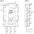
- Fig. 1 is an angle sensor module 10 for a housing cover (see Fig. 5 and 8th ).
- the angle sensor module 10 has a leadframe 12 with free contact ends 14, 16, 18, which serve as electrical contacts for connection to another leadframe in the housing cover, which also has a customer connector 20 (see FIG Fig. 5 and 6 ), which can be configured according to customer requirements.
- the three electrical contacts 14, 16, 18 of the leadframe 12 are connected via bonded electrical connections 22 with a circuit 24 directly, which is an evaluation electronics for a transducer 26.
- the transducer 26, which may be formed, for example, as a magnetoresistive sensor or as a Hall sensor is in turn connected via bonded leads 28 to the evaluation electronics 24.
- capacitors 30 are provided between the contacts 14, 16, 18, which improve the electromagnetic compatibility of the angle sensor module 10.
- the leadframe 12 with the contacted electrical components 24, 26, 30 is overmolded or encapsulated with a thermoset 32, which makes the angle sensor module insensitive to external influences.
- the illustrated angle sensor module 10 is finally used in a housing cover, wherein the positioning can be done via holes 34 or by stop edges 36 of the lead frame itself. This will be related later Fig. 5 and 6 discussed in more detail.
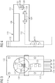
- thermoset coating 132 is firstly produced around a leadframe 112 with electrically connected electronic components 124, 126, 130, and then the angle sensor module is inserted into the housing cover.
- This in Fig. 3 shown angle sensor module has a redundant sensor with two sensors 126 which are arranged parallel to each other on both sides of an end 127 of a Z-shaped angled lead frame 112.
- the transducers 126 are connected by connections 128 not directly associated with evaluation electronics 124, but via traces of the lead frame, which then are in turn connected via connections 129 to the evaluation circuits 124.
- Due to the here Z-shaped design of the lead frame 112 is formed after encapsulation with the thermoset 132, a cylindrical dome 134 which has partially rib-shaped recesses 136. With this design, it is possible to arrange both transducers 126 in a homogeneous magnetic field, which is formed by the projection 134 surrounding magnetic elements.
- the angle sensor module 110 has four connection contacts 114, 116, 118, 119, which in turn are angled. Since at the in 3 and 4 shown angle sensor module 110 two output channels are provided, three capacitors 130 are necessary to improve the electromagnetic compatibility.
- Fig. 5 shows in cross section a housing cover 11 having a recess 40 in which an angle sensor module 210 is inserted.
- the housing cover 11 has a second leadframe 42, which is encapsulated to form the housing with thermoplastic or thermosetting plastic.
- the second leadframe 42 forms a custom-designed connector 20 to which, for example, a plug for connection to the control unit of a motor can be connected.
- the leadframe On the opposite inside of the housing, the leadframe has electrical contact terminals 44, 45, 47 which serve for connection to the electrical terminals 14, 16, 18 of the angle sensor module 10.
- Is shown in Fig. 5 also a rotary magnet 46 which sits on a shaft 48 of an actuator (not shown) and whose angular position can be detected by means of the angle sensor module.
- the transducer 26 is at the here and in Fig. 6 shown angle sensor module 210 positioned according to the position of the rotary magnet 46.
- connection of the previously described angle sensor module 210 to the housing cover 11 is effected by simple pressing, wherein in the contact region between the electrical terminals 214, 216, 218 of the angle sensor module 210 and the electrical contact terminals 44, 45, 47 of the second leadframe 42 of the housing cover 11 known plug-in connections 50 are provided in which spring tongues 52 abut sharp contact with the contact. Since such connectors ensure their strong clamping and a good and accurate mechanical support, skilful dimensioning can be dispensed with further attachment measures, the positioning can be done via dowel pins (not shown) on the plastic housing of the housing cover 11, in the holes 34 of Angle sensor module 210 (see also Fig. 1 and 2 ) intervene. To improve the hold and avoid displacement of the angle sensor module at, for example, high accelerations, an adhesive layer 54 may be provided between the angle sensor module 210 and the housing cover 11.
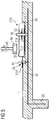
- a further embodiment of an angle sensor module 310 is shown, in which the leadframe 312 in the region of the transducer 26 is embossed trapezoidal, so that it is closer to the rotary magnet 46, ie the thermoset layer between the magnet 46 and the sensor is minimized, thereby results in a better measurement accuracy and the use of smaller magnets is made possible.
- the arrangement of the evaluation electronics 24 and the capacitor 30 corresponds to the in Fig. 6 shown embodiment.
- Fig. 8 again shows a housing cover 11, which is substantially the in Fig. 5 shown housing cover, wherein only the electrical contact terminals 44, 45, 47 are directly adjacent to each other and should not serve the mechanical fixation of the angle sensor module.
- the electrical connection between the terminal lugs 14, 16, 18 of the angle sensor module and the electrical contact terminals 44, 45, 47 takes place here by welding, while the support of the angle sensor module 10, that of the embodiment according to FIG Fig. 1 corresponds to the housing cover 11 is effected primarily by the adhesive layer 54.
- the positioning is again carried out with the aid of the bores 34 and the dowel pins (not shown) assigned to the housing cover 11 or with the aid of a clamping and / or latching connection between the angle sensor module and the housing cover.
Claims (15)
- Procédé de fabrication d'un élément porteur (11) comprenant un capteur d'angle (10) pour un actionneur d'un moteur à combustion interne destiné à détecter l'angle de rotation d'un arbre (48) et comprenant des bornes à enfichage (20) électriques, l'élément porteur se composant de matière plastique et des composants électroniques (12, 24, 26, 30) du capteur d'angle étant surmoulés ou enrobés avec une matière plastique,
le capteur d'angle (10) comprenant des composants électroniques (12, 24, 26, 30) avec au moins un enregistreur de valeur mesurée (26), lequel est configuré pour détecter la position d'un aimant (46) reposant sur un arbre (48) de l'actionneur et mobile en rotation, un circuit d'interprétation (24) destiné à interpréter le signal d'enregistreur de valeur mesurée correspondant et des condensateurs (30) destinés à améliorer la compatibilité électromagnétique,
en tant que composants électroniques du capteur d'angle (10), au moins l'enregistreur de valeur mesurée (26), au moins le circuit d'interprétation (24) associé à l'enregistreur de valeur mesurée (26) et les condensateurs (30) étant reliés électriquement directement à une grille de connexion (12),
la grille de connexion (12) avec les composants (24, 26, 30) reliés électriquement étant surmoulée ou enrobée avec une résine thermodurcissable (32) en vue de former un module capteur d'angle (10) de telle sorte que l'au moins un enregistreur de valeur mesurée (26) ne possède qu'une seule couche de résine thermodurcissable en tant que paroi intermédiaire par rapport à l'aimant (46),
le module capteur d'angle (10) étant finalement introduit dans un logement (40) de l'élément porteur (11), fixé et ensuite relié aux bornes à enfichage (20),
l'élément porteur (11) en tant que couvercle de boîtier en résine thermodurcissable ou en thermoplastique étant moulé par injection avec les bornes à enfichage (20). - Procédé selon la revendication 1, l'établissement du contact avec les composants (24, 26, 30) s'effectuant par métallisation, brasage et/ou collage conducteur.
- Procédé selon l'une des revendications précédentes, la grille de connexion (12) étant positionnée par application directe à des endroits définis sur l'élément porteur ou dans le couvercle de boîtier.
- Procédé selon l'une des revendications précédentes, la grille de connexion (112) étant cintrée en forme de Z ou en forme de L, un enregistreur de mesure (126) ou deux enregistreurs de mesure l'un à côté de l'autre latéralement étant respectivement reliés électriquement de chaque côté à l'extrémité (127) de la grille de connexion (112) qui fait saillie à l'intérieur du boîtier et la zone de la grille de connexion (112) qui fait saillie vers l'intérieur étant entièrement surmoulée ou enrobée avec de la résine thermodurcissable.
- Procédé selon la revendication 4, la résine thermodurcissable étant évidée à la manière de nervures dans la zone du dôme (134).
- Procédé selon l'une des revendications précédentes, le module capteur d'angle (10) étant relié mécaniquement et/ou électriquement à l'élément porteur (11) par le biais de liaisons à enfichage (50) avec effet de serrage.
- Procédé selon l'une des revendications 1 à 5, la grille de connexion du module capteur d'angle (10) étant reliée électriquement à la grille de connexion (42) de l'élément porteur (11) par le biais d'une connexion brasée ou soudée.
- Procédé selon l'une des revendications précédentes, le module capteur d'angle (10) étant collé à l'élément porteur (11) .
- Élément porteur (11) comprenant un capteur d'angle (10) pour un actionneur d'un moteur à combustion interne, le capteur d'angle comprenant des composants électroniques (24, 26, 30) avec au moins un enregistreur de valeur mesurée (26), lequel est configuré pour détecter la position d'un aimant (46) reposant sur un arbre (48) de l'actionneur et mobile en rotation, et un circuit d'interprétation (24) destiné à interpréter le signal d'enregistreur de valeur mesurée correspondant, et étant équipé de bornes à enfichage (20) électriques,
l'élément porteur (11) lui-même étant fabriqué en matière plastique et un module capteur d'angle (10) séparé étant relié mécaniquement et électriquement à l'élément porteur, le module capteur d'angle (10) possédant une grille de connexion (12) qui est reliée aux composants électriques (24, 26, 30) du capteur d'angle et la grille de connexion (12) avec les composants électroniques (24, 26, 30) étant surmoulée ou enrobée avec une résine thermodurcissable (32) séparément de l'élément porteur, la grille de connexion (12) du module capteur d'angle étant entièrement entourée de résine thermodurcissable (32) de manière électriquement isolante dans la zone entre l'au moins un enregistreur de valeur mesurée (26) et le circuit d'interprétation (24) et l'au moins un enregistreur de valeur mesurée (26) ne possédant qu'une seule couche de résine thermodurcissable en tant que paroi intermédiaire par rapport à l'aimant (46),
l'élément porteur (11) en tant que couvercle de boîtier en résine thermodurcissable ou en thermoplastique étant réalisé par moulage par injection avec les bornes à enfichage (20) et au moins un condensateur (30) étant relié électriquement à la grille de connexion, lequel est également surmoulé dans le module capteur d'angle (10). - Élément porteur selon la revendication 9, l'au moins un enregistreur de valeur mesurée (26) étant réalisé sous la forme d'un enregistreur de valeur mesurée basé sur le magnétisme comprenant des éléments magnétorésistifs ou comprenant au moins un élément à effet Hall.
- Élément porteur selon l'une des revendications 9 et 10, deux enregistreurs de valeur mesurée (126) étant disposés parallèlement l'un à l'autre des deux côtés de la grille de connexion (112) ou deux enregistreurs de valeur mesurée étant disposés l'un à côté de l'autre sur un côté de la grille de connexion et étant reliés électriquement à au moins une électronique d'interprétation (124).
- Élément porteur selon la revendication 11, les deux enregistreurs de valeur mesurée (126) étant disposés parallèlement à la surface frontale d'un dôme cylindrique (134) en résine thermodurcissable, dans celui-ci, la grille de connexion (12) pénétrant dans cette partie saillante (134).
- Élément porteur selon la revendication 12, le dôme (134) possédant des évidements (136) de type nervure.
- Élément porteur selon l'une des revendications 9 à 13, la grille de connexion (12) étant configurée dans la zone de l'enregistreur de valeur mesurée (26) par un pliage trapézoïdal ou un estampage (312) de telle sorte que l'épaisseur de paroi en matière plastique est réduite au minimum sans la zone de l'enregistreur de valeur mesurée.
- Élément porteur selon l'une des revendications 9 à 14, des liaisons à enfichage électriques se trouvant entre une grille de connexion (42) de l'élément porteur et le module capteur d'angle (10).
Applications Claiming Priority (2)
| Application Number | Priority Date | Filing Date | Title |
|---|---|---|---|
| DE102006046984A DE102006046984A1 (de) | 2006-10-04 | 2006-10-04 | Verfahren zur Herstellung eines Trägerelements mit einem Winkelsensor |
| PCT/EP2007/060291 WO2008040680A1 (fr) | 2006-10-04 | 2007-09-28 | Procédé pour la fabrication d'un élément porteur avec un détecteur d'angle |
Publications (2)
| Publication Number | Publication Date |
|---|---|
| EP2087320A1 EP2087320A1 (fr) | 2009-08-12 |
| EP2087320B1 true EP2087320B1 (fr) | 2019-11-06 |
Family
ID=38695470
Family Applications (1)
| Application Number | Title | Priority Date | Filing Date |
|---|---|---|---|
| EP07820678.6A Active EP2087320B1 (fr) | 2006-10-04 | 2007-09-28 | Procédé pour la fabrication d'un élément porteur avec un détecteur d'angle |
Country Status (7)
| Country | Link |
|---|---|
| US (1) | US8339124B2 (fr) |
| EP (1) | EP2087320B1 (fr) |
| JP (1) | JP5135351B2 (fr) |
| KR (1) | KR101503935B1 (fr) |
| CN (1) | CN101558285B (fr) |
| DE (1) | DE102006046984A1 (fr) |
| WO (1) | WO2008040680A1 (fr) |
Families Citing this family (18)
| Publication number | Priority date | Publication date | Assignee | Title |
|---|---|---|---|---|
| DE102009006529A1 (de) | 2009-01-28 | 2010-08-26 | Continental Automotive Gmbh | Positionssensor |
| US8901921B2 (en) * | 2009-11-25 | 2014-12-02 | Infineon Technologies Ag | Angle measurement system for determining an angular position of a rotating shaft |
| DE102010047128A1 (de) * | 2010-09-30 | 2012-04-05 | Infineon Technologies Ag | Hallsensoranordnung zum redundanten Messen eines Magnetfeldes |
| EP2749156A1 (fr) * | 2011-08-24 | 2014-07-02 | Continental Teves AG&Co. Ohg | Capteur comportant un moyen de support électrique unique |
| DE102011118773B4 (de) | 2011-11-17 | 2023-10-05 | Hartmann-Exact Gmbh | Vorrichtung zur berührungslosen Erfassung der Relativposition zweier relativ zueinander bewegbarer Teile |
| DE102012224075A1 (de) | 2012-12-20 | 2014-06-26 | Continental Teves Ag & Co. Ohg | Sensor zum Erfassen einer Position eines Geberelements |
| DE102013213053A1 (de) * | 2013-07-04 | 2015-01-08 | Continental Automotive Gmbh | Drehwinkelsensorvorrichtung mit redundanten Sensoreinheiten |
| DE102013213054A1 (de) * | 2013-07-04 | 2015-01-08 | Continental Automotive Gmbh | Drehwinkelsensorvorrichtung mit redundanten Sensoreinheiten zum Bestimmen eines eindeutigen Winkelsignals |
| EP3052828B1 (fr) * | 2013-10-02 | 2020-11-11 | Schaeffler Technologies AG & Co. KG | Agencement piston-cylindre |
| JP6017401B2 (ja) * | 2013-11-05 | 2016-11-02 | 愛三工業株式会社 | 回転角度検出センサ |
| DK3158345T3 (da) * | 2014-06-20 | 2024-02-19 | Xcerra Corp | Teststikanordning og relaterede fremgangsmåder |
| DE102014218544A1 (de) * | 2014-09-16 | 2016-03-17 | Schaeffler Technologies AG & Co. KG | Sensorikeinheit zur Bestimmung einer Rotorlage eines Elektromotors und ein Elektromotor, vozugsweise für einen Kupplungsaktor eines Kupplungsbetätigungssystems eines Kraftfahrzeuges |
| DE102015207310A1 (de) * | 2015-04-22 | 2016-10-27 | Zf Friedrichshafen Ag | Elektronikmodul und Verfahren zum Umkapseln desselben |
| FR3040213B1 (fr) * | 2015-08-18 | 2017-09-15 | Continental Automotive France | Procede de fabrication d'un capteur de mesure pour vehicule automobile |
| ITUB20160271A1 (it) * | 2016-01-29 | 2017-07-29 | Magneti Marelli Spa | Metodo per l'assemblaggio di un sensore in un componente elettromeccanico per un motore a combustione interna e componente elettromeccanico ottenuto mediante tale metodo |
| US10251295B2 (en) * | 2016-02-01 | 2019-04-02 | Alps Alpine Co., Ltd. | Electronic device and method of producing the same |
| JP2018049942A (ja) * | 2016-09-21 | 2018-03-29 | アイシン精機株式会社 | 変位センサ |
| DE102019210375A1 (de) * | 2019-07-12 | 2021-01-14 | Continental Teves Ag & Co. Ohg | Verfahren zur Herstellung eines robusten Sensors |
Citations (6)
| Publication number | Priority date | Publication date | Assignee | Title |
|---|---|---|---|---|
| US5637995A (en) * | 1992-12-09 | 1997-06-10 | Nippondenso Co., Ltd. | Magnetic detection device having a magnet including a stepped portion for eliminating turbulence at the MR sensor |
| DE10054123A1 (de) * | 1999-11-01 | 2001-05-03 | Denso Corp | Drehwinkelerfasser mit einer Sensorabdeckung, durch die ein Magnetsensorelement und ein Aussenverbindungsanschluss einstückig gestaltet sind |
| WO2003006805A1 (fr) * | 2001-07-11 | 2003-01-23 | Siemens Aktiengesellschaft | Procede de detection sans contact de la position d'un axe de volet de reglage d'un support de volet de reglage, et support de volet de reglage y relatif |
| JP2004004114A (ja) * | 1999-11-01 | 2004-01-08 | Denso Corp | 回転角検出装置 |
| WO2006024626A2 (fr) * | 2004-08-31 | 2006-03-09 | Siemens Aktiengesellschaft | Module electrique |
| EP1669573A2 (fr) * | 2004-12-08 | 2006-06-14 | Siemens Aktiengesellschaft | Sous assemblage pour l'actuation d'un arbre tournant dont la position angulaire est à détecter de manière continue |
Family Cites Families (13)
| Publication number | Priority date | Publication date | Assignee | Title |
|---|---|---|---|---|
| JPH0419114A (ja) * | 1990-05-15 | 1992-01-23 | Mitsubishi Electric Corp | インサート電極モールド体の製造方法 |
| DE19618631A1 (de) * | 1996-05-09 | 1997-11-13 | Teves Gmbh Alfred | Vorrichtung zur Messung von Dreh- oder Winkelbewegungen und ein Verfahren zur Herstellung dieser Vorrichtung |
| JPH11237395A (ja) * | 1998-02-23 | 1999-08-31 | Honda Motor Co Ltd | 回転センサ及び回転センサ用磁気検出ic |
| JPH11304894A (ja) * | 1998-04-23 | 1999-11-05 | Mitsubishi Electric Corp | 磁気検出装置とその製造方法 |
| US6305921B1 (en) * | 1999-07-12 | 2001-10-23 | Accu-Mold Corp. | Saw tooth mold |
| JP3830319B2 (ja) * | 1999-12-16 | 2006-10-04 | 株式会社デンソー | 回転角度検出センサの温度特性調整方法 |
| DE10133559B4 (de) * | 2001-07-13 | 2005-01-27 | Siemens Ag | Magnetoresistiver Winkelsensor |
| JP4190780B2 (ja) * | 2002-03-18 | 2008-12-03 | 株式会社デンソー | 回転検出装置 |
| JP3720801B2 (ja) * | 2002-10-24 | 2005-11-30 | 三菱電機株式会社 | 磁気検出装置 |
| US7425824B2 (en) * | 2005-05-20 | 2008-09-16 | Honeywell International Inc. | Magnetoresistive sensor |
| US7378721B2 (en) * | 2005-12-05 | 2008-05-27 | Honeywell International Inc. | Chip on lead frame for small package speed sensor |
| US7375406B2 (en) * | 2005-12-20 | 2008-05-20 | Honeywell International Inc. | Thermoplastic overmolding for small package turbocharger speed sensor |
| US20080218158A1 (en) * | 2007-03-07 | 2008-09-11 | Carlson Joseph D | Rotary position sensor |
-
2006
- 2006-10-04 DE DE102006046984A patent/DE102006046984A1/de active Pending
-
2007
- 2007-09-28 KR KR1020097009178A patent/KR101503935B1/ko active IP Right Grant
- 2007-09-28 EP EP07820678.6A patent/EP2087320B1/fr active Active
- 2007-09-28 WO PCT/EP2007/060291 patent/WO2008040680A1/fr active Application Filing
- 2007-09-28 CN CN2007800373594A patent/CN101558285B/zh active Active
- 2007-09-28 JP JP2009530854A patent/JP5135351B2/ja active Active
- 2007-09-28 US US12/444,564 patent/US8339124B2/en active Active
Patent Citations (6)
| Publication number | Priority date | Publication date | Assignee | Title |
|---|---|---|---|---|
| US5637995A (en) * | 1992-12-09 | 1997-06-10 | Nippondenso Co., Ltd. | Magnetic detection device having a magnet including a stepped portion for eliminating turbulence at the MR sensor |
| DE10054123A1 (de) * | 1999-11-01 | 2001-05-03 | Denso Corp | Drehwinkelerfasser mit einer Sensorabdeckung, durch die ein Magnetsensorelement und ein Aussenverbindungsanschluss einstückig gestaltet sind |
| JP2004004114A (ja) * | 1999-11-01 | 2004-01-08 | Denso Corp | 回転角検出装置 |
| WO2003006805A1 (fr) * | 2001-07-11 | 2003-01-23 | Siemens Aktiengesellschaft | Procede de detection sans contact de la position d'un axe de volet de reglage d'un support de volet de reglage, et support de volet de reglage y relatif |
| WO2006024626A2 (fr) * | 2004-08-31 | 2006-03-09 | Siemens Aktiengesellschaft | Module electrique |
| EP1669573A2 (fr) * | 2004-12-08 | 2006-06-14 | Siemens Aktiengesellschaft | Sous assemblage pour l'actuation d'un arbre tournant dont la position angulaire est à détecter de manière continue |
Also Published As
| Publication number | Publication date |
|---|---|
| WO2008040680A1 (fr) | 2008-04-10 |
| KR20090097849A (ko) | 2009-09-16 |
| CN101558285A (zh) | 2009-10-14 |
| CN101558285B (zh) | 2012-11-14 |
| JP5135351B2 (ja) | 2013-02-06 |
| US8339124B2 (en) | 2012-12-25 |
| EP2087320A1 (fr) | 2009-08-12 |
| KR101503935B1 (ko) | 2015-03-24 |
| US20100109654A1 (en) | 2010-05-06 |
| JP2010506157A (ja) | 2010-02-25 |
| DE102006046984A1 (de) | 2008-04-10 |
Similar Documents
| Publication | Publication Date | Title |
|---|---|---|
| EP2087320B1 (fr) | Procédé pour la fabrication d'un élément porteur avec un détecteur d'angle | |
| DE102007054905B4 (de) | Rotationswinkelsensoren und Drosseleinrichtungen | |
| EP2366096B1 (fr) | Kit pour un moteur électrique avec un capteur angulaire | |
| DE4008141C2 (de) | Sensor mit Hall-Effekt | |
| DE202008009002U1 (de) | Magnetfeldsensor | |
| EP2223125B1 (fr) | Élément de détection de champ magnétique | |
| DE102011018180A1 (de) | Rotationswinkelsensoren und Herstellungsverfahren dafür | |
| DE102014226483A1 (de) | Positionserfassungseinrichtung | |
| EP1828720B1 (fr) | Ensemble capteur magnetique | |
| AT411639B (de) | Verfahren zum herstellen einer kunststoffumspritzten leiterstruktur sowie elektrische schaltungseinheit mit einer kunststoffumspritzten leiterstruktur | |
| EP0977979B1 (fr) | Procede pour fabriquer un module detecteur et module detecteur ainsi obtenu | |
| EP2520142B1 (fr) | Capteur doté d'un boîtier et procédé de fabrication correspondant | |
| DE202009000925U1 (de) | Moduleinheit | |
| DE4219923C2 (de) | Magnet-Sensor | |
| DE19848081A1 (de) | Antriebseinrichtung mit einem Stellantrieb | |
| EP2265102A1 (fr) | Structure de capteur sans boîtier | |
| DE202005013344U1 (de) | Elektrische Moduleinheit und Sensor | |
| EP1546529B1 (fr) | Couvercle | |
| EP2936515B1 (fr) | Procédé de production d'un capteur de mesure | |
| DE19744673C2 (de) | Vorrichtung zur Erfassung der Drehzahl eines umlaufenden Bauteiles, insbesondere für ein Kraftfahrzeug | |
| DE102011081222B4 (de) | Sensorbaugruppe | |
| WO2008049690A1 (fr) | Détecteur de champ magnétique | |
| WO2011064245A1 (fr) | Capteur de couple de rotation | |
| EP3685124B1 (fr) | Support pour une unité de détection | |
| EP2615426A1 (fr) | Capteur |
Legal Events
| Date | Code | Title | Description |
|---|---|---|---|
| PUAI | Public reference made under article 153(3) epc to a published international application that has entered the european phase |
Free format text: ORIGINAL CODE: 0009012 |
|
| 17P | Request for examination filed |
Effective date: 20090504 |
|
| AK | Designated contracting states |
Kind code of ref document: A1 Designated state(s): AT BE BG CH CY CZ DE DK EE ES FI FR GB GR HU IE IS IT LI LT LU LV MC MT NL PL PT RO SE SI SK TR |
|
| DAX | Request for extension of the european patent (deleted) | ||
| RAP1 | Party data changed (applicant data changed or rights of an application transferred) |
Owner name: CONTINENTAL AUTOMOTIVE GMBH |
|
| 17Q | First examination report despatched |
Effective date: 20140728 |
|
| STAA | Information on the status of an ep patent application or granted ep patent |
Free format text: STATUS: EXAMINATION IS IN PROGRESS |
|
| GRAP | Despatch of communication of intention to grant a patent |
Free format text: ORIGINAL CODE: EPIDOSNIGR1 |
|
| STAA | Information on the status of an ep patent application or granted ep patent |
Free format text: STATUS: GRANT OF PATENT IS INTENDED |
|
| GRAJ | Information related to disapproval of communication of intention to grant by the applicant or resumption of examination proceedings by the epo deleted |
Free format text: ORIGINAL CODE: EPIDOSDIGR1 |
|
| STAA | Information on the status of an ep patent application or granted ep patent |
Free format text: STATUS: EXAMINATION IS IN PROGRESS |
|
| INTG | Intention to grant announced |
Effective date: 20180820 |
|
| INTC | Intention to grant announced (deleted) | ||
| GRAP | Despatch of communication of intention to grant a patent |
Free format text: ORIGINAL CODE: EPIDOSNIGR1 |
|
| STAA | Information on the status of an ep patent application or granted ep patent |
Free format text: STATUS: GRANT OF PATENT IS INTENDED |
|
| INTG | Intention to grant announced |
Effective date: 20190318 |
|
| GRAS | Grant fee paid |
Free format text: ORIGINAL CODE: EPIDOSNIGR3 |
|
| RAP1 | Party data changed (applicant data changed or rights of an application transferred) |
Owner name: CPT GROUP GMBH |
|
| GRAA | (expected) grant |
Free format text: ORIGINAL CODE: 0009210 |
|
| STAA | Information on the status of an ep patent application or granted ep patent |
Free format text: STATUS: THE PATENT HAS BEEN GRANTED |
|
| AK | Designated contracting states |
Kind code of ref document: B1 Designated state(s): AT BE BG CH CY CZ DE DK EE ES FI FR GB GR HU IE IS IT LI LT LU LV MC MT NL PL PT RO SE SI SK TR |
|
| REG | Reference to a national code |
Ref country code: GB Ref legal event code: FG4D Free format text: NOT ENGLISH |
|
| REG | Reference to a national code |
Ref country code: CH Ref legal event code: EP Ref country code: AT Ref legal event code: REF Ref document number: 1199360 Country of ref document: AT Kind code of ref document: T Effective date: 20191115 |
|
| REG | Reference to a national code |
Ref country code: IE Ref legal event code: FG4D Free format text: LANGUAGE OF EP DOCUMENT: GERMAN |
|
| REG | Reference to a national code |
Ref country code: DE Ref legal event code: R096 Ref document number: 502007016802 Country of ref document: DE |
|
| RAP2 | Party data changed (patent owner data changed or rights of a patent transferred) |
Owner name: VITESCO TECHNOLOGIES GMBH |
|
| REG | Reference to a national code |
Ref country code: DE Ref legal event code: R081 Ref document number: 502007016802 Country of ref document: DE Owner name: VITESCO TECHNOLOGIES GMBH, DE Free format text: FORMER OWNER: CPT GROUP GMBH, 30165 HANNOVER, DE |
|
| REG | Reference to a national code |
Ref country code: NL Ref legal event code: MP Effective date: 20191106 |
|
| REG | Reference to a national code |
Ref country code: LT Ref legal event code: MG4D |
|
| PG25 | Lapsed in a contracting state [announced via postgrant information from national office to epo] |
Ref country code: GR Free format text: LAPSE BECAUSE OF FAILURE TO SUBMIT A TRANSLATION OF THE DESCRIPTION OR TO PAY THE FEE WITHIN THE PRESCRIBED TIME-LIMIT Effective date: 20200207 Ref country code: BG Free format text: LAPSE BECAUSE OF FAILURE TO SUBMIT A TRANSLATION OF THE DESCRIPTION OR TO PAY THE FEE WITHIN THE PRESCRIBED TIME-LIMIT Effective date: 20200206 Ref country code: FI Free format text: LAPSE BECAUSE OF FAILURE TO SUBMIT A TRANSLATION OF THE DESCRIPTION OR TO PAY THE FEE WITHIN THE PRESCRIBED TIME-LIMIT Effective date: 20191106 Ref country code: LV Free format text: LAPSE BECAUSE OF FAILURE TO SUBMIT A TRANSLATION OF THE DESCRIPTION OR TO PAY THE FEE WITHIN THE PRESCRIBED TIME-LIMIT Effective date: 20191106 Ref country code: ES Free format text: LAPSE BECAUSE OF FAILURE TO SUBMIT A TRANSLATION OF THE DESCRIPTION OR TO PAY THE FEE WITHIN THE PRESCRIBED TIME-LIMIT Effective date: 20191106 Ref country code: SE Free format text: LAPSE BECAUSE OF FAILURE TO SUBMIT A TRANSLATION OF THE DESCRIPTION OR TO PAY THE FEE WITHIN THE PRESCRIBED TIME-LIMIT Effective date: 20191106 Ref country code: PT Free format text: LAPSE BECAUSE OF FAILURE TO SUBMIT A TRANSLATION OF THE DESCRIPTION OR TO PAY THE FEE WITHIN THE PRESCRIBED TIME-LIMIT Effective date: 20200306 Ref country code: LT Free format text: LAPSE BECAUSE OF FAILURE TO SUBMIT A TRANSLATION OF THE DESCRIPTION OR TO PAY THE FEE WITHIN THE PRESCRIBED TIME-LIMIT Effective date: 20191106 Ref country code: PL Free format text: LAPSE BECAUSE OF FAILURE TO SUBMIT A TRANSLATION OF THE DESCRIPTION OR TO PAY THE FEE WITHIN THE PRESCRIBED TIME-LIMIT Effective date: 20191106 Ref country code: NL Free format text: LAPSE BECAUSE OF FAILURE TO SUBMIT A TRANSLATION OF THE DESCRIPTION OR TO PAY THE FEE WITHIN THE PRESCRIBED TIME-LIMIT Effective date: 20191106 |
|
| REG | Reference to a national code |
Ref country code: DE Ref legal event code: R084 Ref document number: 502007016802 Country of ref document: DE |
|
| PG25 | Lapsed in a contracting state [announced via postgrant information from national office to epo] |
Ref country code: IS Free format text: LAPSE BECAUSE OF FAILURE TO SUBMIT A TRANSLATION OF THE DESCRIPTION OR TO PAY THE FEE WITHIN THE PRESCRIBED TIME-LIMIT Effective date: 20200306 |
|
| PG25 | Lapsed in a contracting state [announced via postgrant information from national office to epo] |
Ref country code: DK Free format text: LAPSE BECAUSE OF FAILURE TO SUBMIT A TRANSLATION OF THE DESCRIPTION OR TO PAY THE FEE WITHIN THE PRESCRIBED TIME-LIMIT Effective date: 20191106 Ref country code: EE Free format text: LAPSE BECAUSE OF FAILURE TO SUBMIT A TRANSLATION OF THE DESCRIPTION OR TO PAY THE FEE WITHIN THE PRESCRIBED TIME-LIMIT Effective date: 20191106 Ref country code: RO Free format text: LAPSE BECAUSE OF FAILURE TO SUBMIT A TRANSLATION OF THE DESCRIPTION OR TO PAY THE FEE WITHIN THE PRESCRIBED TIME-LIMIT Effective date: 20191106 Ref country code: CZ Free format text: LAPSE BECAUSE OF FAILURE TO SUBMIT A TRANSLATION OF THE DESCRIPTION OR TO PAY THE FEE WITHIN THE PRESCRIBED TIME-LIMIT Effective date: 20191106 |
|
| REG | Reference to a national code |
Ref country code: DE Ref legal event code: R097 Ref document number: 502007016802 Country of ref document: DE |
|
| PG25 | Lapsed in a contracting state [announced via postgrant information from national office to epo] |
Ref country code: SK Free format text: LAPSE BECAUSE OF FAILURE TO SUBMIT A TRANSLATION OF THE DESCRIPTION OR TO PAY THE FEE WITHIN THE PRESCRIBED TIME-LIMIT Effective date: 20191106 |
|
| PLBE | No opposition filed within time limit |
Free format text: ORIGINAL CODE: 0009261 |
|
| STAA | Information on the status of an ep patent application or granted ep patent |
Free format text: STATUS: NO OPPOSITION FILED WITHIN TIME LIMIT |
|
| 26N | No opposition filed |
Effective date: 20200807 |
|
| PG25 | Lapsed in a contracting state [announced via postgrant information from national office to epo] |
Ref country code: SI Free format text: LAPSE BECAUSE OF FAILURE TO SUBMIT A TRANSLATION OF THE DESCRIPTION OR TO PAY THE FEE WITHIN THE PRESCRIBED TIME-LIMIT Effective date: 20191106 |
|
| PG25 | Lapsed in a contracting state [announced via postgrant information from national office to epo] |
Ref country code: MC Free format text: LAPSE BECAUSE OF FAILURE TO SUBMIT A TRANSLATION OF THE DESCRIPTION OR TO PAY THE FEE WITHIN THE PRESCRIBED TIME-LIMIT Effective date: 20191106 |
|
| REG | Reference to a national code |
Ref country code: CH Ref legal event code: PL |
|
| GBPC | Gb: european patent ceased through non-payment of renewal fee |
Effective date: 20200928 |
|
| REG | Reference to a national code |
Ref country code: BE Ref legal event code: MM Effective date: 20200930 |
|
| PG25 | Lapsed in a contracting state [announced via postgrant information from national office to epo] |
Ref country code: LU Free format text: LAPSE BECAUSE OF NON-PAYMENT OF DUE FEES Effective date: 20200928 |
|
| PG25 | Lapsed in a contracting state [announced via postgrant information from national office to epo] |
Ref country code: IE Free format text: LAPSE BECAUSE OF NON-PAYMENT OF DUE FEES Effective date: 20200928 Ref country code: GB Free format text: LAPSE BECAUSE OF NON-PAYMENT OF DUE FEES Effective date: 20200928 Ref country code: LI Free format text: LAPSE BECAUSE OF NON-PAYMENT OF DUE FEES Effective date: 20200930 Ref country code: BE Free format text: LAPSE BECAUSE OF NON-PAYMENT OF DUE FEES Effective date: 20200930 Ref country code: CH Free format text: LAPSE BECAUSE OF NON-PAYMENT OF DUE FEES Effective date: 20200930 |
|
| REG | Reference to a national code |
Ref country code: AT Ref legal event code: MM01 Ref document number: 1199360 Country of ref document: AT Kind code of ref document: T Effective date: 20200928 |
|
| REG | Reference to a national code |
Ref country code: DE Ref legal event code: R081 Ref document number: 502007016802 Country of ref document: DE Owner name: VITESCO TECHNOLOGIES GMBH, DE Free format text: FORMER OWNER: VITESCO TECHNOLOGIES GMBH, 30165 HANNOVER, DE |
|
| PG25 | Lapsed in a contracting state [announced via postgrant information from national office to epo] |
Ref country code: AT Free format text: LAPSE BECAUSE OF NON-PAYMENT OF DUE FEES Effective date: 20200928 |
|
| PG25 | Lapsed in a contracting state [announced via postgrant information from national office to epo] |
Ref country code: TR Free format text: LAPSE BECAUSE OF FAILURE TO SUBMIT A TRANSLATION OF THE DESCRIPTION OR TO PAY THE FEE WITHIN THE PRESCRIBED TIME-LIMIT Effective date: 20191106 Ref country code: MT Free format text: LAPSE BECAUSE OF FAILURE TO SUBMIT A TRANSLATION OF THE DESCRIPTION OR TO PAY THE FEE WITHIN THE PRESCRIBED TIME-LIMIT Effective date: 20191106 Ref country code: CY Free format text: LAPSE BECAUSE OF FAILURE TO SUBMIT A TRANSLATION OF THE DESCRIPTION OR TO PAY THE FEE WITHIN THE PRESCRIBED TIME-LIMIT Effective date: 20191106 |
|
| P01 | Opt-out of the competence of the unified patent court (upc) registered |
Effective date: 20230530 |
|
| PGFP | Annual fee paid to national office [announced via postgrant information from national office to epo] |
Ref country code: FR Payment date: 20230928 Year of fee payment: 17 Ref country code: DE Payment date: 20230930 Year of fee payment: 17 |
|
| PGFP | Annual fee paid to national office [announced via postgrant information from national office to epo] |
Ref country code: IT Payment date: 20230927 Year of fee payment: 17 |