EP2087320B1 - Verfahren zur herstellung eines trägerelements mit einem winkelsensor - Google Patents
Verfahren zur herstellung eines trägerelements mit einem winkelsensor Download PDFInfo
- Publication number
- EP2087320B1 EP2087320B1 EP07820678.6A EP07820678A EP2087320B1 EP 2087320 B1 EP2087320 B1 EP 2087320B1 EP 07820678 A EP07820678 A EP 07820678A EP 2087320 B1 EP2087320 B1 EP 2087320B1
- Authority
- EP
- European Patent Office
- Prior art keywords
- angle sensor
- leadframe
- support element
- measured
- sensor module
- Prior art date
- Legal status (The legal status is an assumption and is not a legal conclusion. Google has not performed a legal analysis and makes no representation as to the accuracy of the status listed.)
- Active
Links
- 238000000034 method Methods 0.000 title claims description 12
- 238000004519 manufacturing process Methods 0.000 title claims description 10
- 229920001187 thermosetting polymer Polymers 0.000 claims description 26
- 238000011156 evaluation Methods 0.000 claims description 15
- 239000004033 plastic Substances 0.000 claims description 15
- 229920003023 plastic Polymers 0.000 claims description 15
- 239000003990 capacitor Substances 0.000 claims description 9
- 229920001169 thermoplastic Polymers 0.000 claims description 7
- 239000004416 thermosoftening plastic Substances 0.000 claims description 7
- 238000002485 combustion reaction Methods 0.000 claims description 6
- 238000001746 injection moulding Methods 0.000 claims description 5
- 239000002356 single layer Substances 0.000 claims description 4
- 238000004026 adhesive bonding Methods 0.000 claims description 3
- 238000005476 soldering Methods 0.000 claims description 3
- 238000005192 partition Methods 0.000 claims 2
- 229910000679 solder Inorganic materials 0.000 claims 1
- 238000005538 encapsulation Methods 0.000 description 9
- 238000013461 design Methods 0.000 description 4
- 239000010410 layer Substances 0.000 description 4
- 238000003780 insertion Methods 0.000 description 3
- 230000037431 insertion Effects 0.000 description 3
- 238000003466 welding Methods 0.000 description 3
- 238000009825 accumulation Methods 0.000 description 2
- 239000012790 adhesive layer Substances 0.000 description 2
- 239000004020 conductor Substances 0.000 description 2
- 238000005516 engineering process Methods 0.000 description 2
- 230000007257 malfunction Effects 0.000 description 2
- 239000000463 material Substances 0.000 description 2
- 238000005259 measurement Methods 0.000 description 2
- 239000004065 semiconductor Substances 0.000 description 2
- 229920000965 Duroplast Polymers 0.000 description 1
- 239000004638 Duroplast Substances 0.000 description 1
- 239000004831 Hot glue Substances 0.000 description 1
- 230000001133 acceleration Effects 0.000 description 1
- 239000000853 adhesive Substances 0.000 description 1
- 230000001070 adhesive effect Effects 0.000 description 1
- 238000005266 casting Methods 0.000 description 1
- 239000011248 coating agent Substances 0.000 description 1
- 238000000576 coating method Methods 0.000 description 1
- 238000006073 displacement reaction Methods 0.000 description 1
- 238000002955 isolation Methods 0.000 description 1
- 239000002245 particle Substances 0.000 description 1
- 238000003825 pressing Methods 0.000 description 1
- 210000002105 tongue Anatomy 0.000 description 1
- 238000012549 training Methods 0.000 description 1
Images


Classifications
-
- G—PHYSICS
- G01—MEASURING; TESTING
- G01B—MEASURING LENGTH, THICKNESS OR SIMILAR LINEAR DIMENSIONS; MEASURING ANGLES; MEASURING AREAS; MEASURING IRREGULARITIES OF SURFACES OR CONTOURS
- G01B7/00—Measuring arrangements characterised by the use of electric or magnetic techniques
- G01B7/30—Measuring arrangements characterised by the use of electric or magnetic techniques for measuring angles or tapers; for testing the alignment of axes
- G01B7/31—Measuring arrangements characterised by the use of electric or magnetic techniques for measuring angles or tapers; for testing the alignment of axes for testing the alignment of axes
-
- G—PHYSICS
- G01—MEASURING; TESTING
- G01D—MEASURING NOT SPECIALLY ADAPTED FOR A SPECIFIC VARIABLE; ARRANGEMENTS FOR MEASURING TWO OR MORE VARIABLES NOT COVERED IN A SINGLE OTHER SUBCLASS; TARIFF METERING APPARATUS; MEASURING OR TESTING NOT OTHERWISE PROVIDED FOR
- G01D5/00—Mechanical means for transferring the output of a sensing member; Means for converting the output of a sensing member to another variable where the form or nature of the sensing member does not constrain the means for converting; Transducers not specially adapted for a specific variable
- G01D5/12—Mechanical means for transferring the output of a sensing member; Means for converting the output of a sensing member to another variable where the form or nature of the sensing member does not constrain the means for converting; Transducers not specially adapted for a specific variable using electric or magnetic means
- G01D5/14—Mechanical means for transferring the output of a sensing member; Means for converting the output of a sensing member to another variable where the form or nature of the sensing member does not constrain the means for converting; Transducers not specially adapted for a specific variable using electric or magnetic means influencing the magnitude of a current or voltage
- G01D5/20—Mechanical means for transferring the output of a sensing member; Means for converting the output of a sensing member to another variable where the form or nature of the sensing member does not constrain the means for converting; Transducers not specially adapted for a specific variable using electric or magnetic means influencing the magnitude of a current or voltage by varying inductance, e.g. by a movable armature
-
- G—PHYSICS
- G01—MEASURING; TESTING
- G01D—MEASURING NOT SPECIALLY ADAPTED FOR A SPECIFIC VARIABLE; ARRANGEMENTS FOR MEASURING TWO OR MORE VARIABLES NOT COVERED IN A SINGLE OTHER SUBCLASS; TARIFF METERING APPARATUS; MEASURING OR TESTING NOT OTHERWISE PROVIDED FOR
- G01D5/00—Mechanical means for transferring the output of a sensing member; Means for converting the output of a sensing member to another variable where the form or nature of the sensing member does not constrain the means for converting; Transducers not specially adapted for a specific variable
- G01D5/12—Mechanical means for transferring the output of a sensing member; Means for converting the output of a sensing member to another variable where the form or nature of the sensing member does not constrain the means for converting; Transducers not specially adapted for a specific variable using electric or magnetic means
- G01D5/14—Mechanical means for transferring the output of a sensing member; Means for converting the output of a sensing member to another variable where the form or nature of the sensing member does not constrain the means for converting; Transducers not specially adapted for a specific variable using electric or magnetic means influencing the magnitude of a current or voltage
- G01D5/142—Mechanical means for transferring the output of a sensing member; Means for converting the output of a sensing member to another variable where the form or nature of the sensing member does not constrain the means for converting; Transducers not specially adapted for a specific variable using electric or magnetic means influencing the magnitude of a current or voltage using Hall-effect devices
- G01D5/145—Mechanical means for transferring the output of a sensing member; Means for converting the output of a sensing member to another variable where the form or nature of the sensing member does not constrain the means for converting; Transducers not specially adapted for a specific variable using electric or magnetic means influencing the magnitude of a current or voltage using Hall-effect devices influenced by the relative movement between the Hall device and magnetic fields
-
- G—PHYSICS
- G01—MEASURING; TESTING
- G01R—MEASURING ELECTRIC VARIABLES; MEASURING MAGNETIC VARIABLES
- G01R1/00—Details of instruments or arrangements of the types included in groups G01R5/00 - G01R13/00 and G01R31/00
- G01R1/02—General constructional details
- G01R1/06—Measuring leads; Measuring probes
- G01R1/067—Measuring probes
-
- F—MECHANICAL ENGINEERING; LIGHTING; HEATING; WEAPONS; BLASTING
- F02—COMBUSTION ENGINES; HOT-GAS OR COMBUSTION-PRODUCT ENGINE PLANTS
- F02D—CONTROLLING COMBUSTION ENGINES
- F02D9/00—Controlling engines by throttling air or fuel-and-air induction conduits or exhaust conduits
- F02D9/02—Controlling engines by throttling air or fuel-and-air induction conduits or exhaust conduits concerning induction conduits
- F02D2009/0201—Arrangements; Control features; Details thereof
- F02D2009/0205—Arrangements; Control features; Details thereof working on the throttle valve and another valve, e.g. choke
Definitions
- the present invention relates to a method for producing a carrier element, for example in the form of a housing cover or for insertion in a housing cover, with an angle sensor for detecting the rotational angle of a shaft and with electrical plug-in connections, wherein the support element made of plastic, for.
- a carrier element for example in the form of a housing cover or for insertion in a housing cover
- an angle sensor for detecting the rotational angle of a shaft and with electrical plug-in connections
- the support element made of plastic, for.
- thermoset or thermoplastic and electrical components are encapsulated or encapsulated with a plastic.
- the subject of the present invention is also a carrier element with an angle sensor for an actuator of an internal combustion engine, wherein the angle sensor comprises a magnet associated with the actuator and electronic components and with electrical plug-in connections, for. B. a so-called customer plug equipped.
- Such support elements with integrated angle sensor are used in internal combustion engines, where they detect the rotational position of actuators for the control of the internal combustion engine, for example in the load control, exhaust gas recirculation, air valves in the intake tract or the adjustment of the blades of a turbocharger.
- the design as a housing cover has the advantage that the angle sensor is closed even protected in a unit, wherein the electrical connections are designed as customer plug, which is configured according to customer requirements and allows electrical connection to the engine electronics.
- the actual angle sensor usually consists of at least one magnetoresistive sensor or a Hall sensor, z. B. in semiconductor technology, wherein the Sensor is also assigned in each case a chip with the transmitter. Frequently, the angle sensor also includes capacitors to improve the electromagnetic compatibility.
- the redundant training with two sensors and two associated evaluation electronics to increase the security, for example, when detecting the angular position of a throttle valve (e-gas).
- the production z. B. housing covers with integrated angle sensor is done so far in such a way that the sensor and the transmitter is preconfigured by a chip manufacturer, d. h., The chip for the transmitter and the sensor are electrically connected to a punched grid for contacting to the outside, for example by bonding, and then the electronic components are molded individually with a thermoset. Subsequently, a check is made by the manufacturer and the preconfigured angle sensor is then delivered to a customer. This takes from another manufacturer a housing cover blank made of plastic, which is usually produced by injection molding, and manufactures the angle sensor angle sensor module in that initially the preconfigured angle sensor is electrically connected to a so-called lead frame by welding or soldering. Subsequently, the leadframe is inserted into the housing blank and the leadframe is overmolded with a thermoplastic, wherein a separate cover must protect the sensor, otherwise it would be damaged. Finally, a function check of the finished housing cover must be made again.
- the previous manufacturing process can be characterized by three injection molding operations, with both the partial encapsulation of the stamped grid on the part of the chip manufacturer as well as the final encapsulation of the leadframe for connection to the housing cover must take place under special process conditions in order to avoid the risk of malfunction.
- two functional checks are necessary, namely on the part of the chip manufacturer after completion of the sensor and on the part of the manufacturer of the support element after encapsulation of the leadframe.
- a transducer contains this included in a housing which provided for generating the electrical signal components. Via a connection cable, the signals are led out of the housing.
- the housing consists of two half-shells, which are made of plastic and which are connected after insertion of the electrical components and insertion of the connecting cable by gluing or welding. The interior of the two connected half shells is filled with a hot melt adhesive.
- an integrated circuit electrical assembly that has at least one power semiconductor element and other electronic components connected to each other and to terminals by conductors formed by a beta.
- a rotation angle detector having a sensor cover by which a magnetic sensor element and an external connection terminal are integrally formed is known.
- the object of the present invention is to provide a method for producing a housing cover or other support element with an angle sensor of the type described above, which is simplified compared to the known manufacturing method.
- the electronic components of the angle sensor are electrically connected directly to a leadframe, the leadframe without the carrier element with the electronic components is encapsulated or encapsulated with a thermoset to form an angle sensor module and finally the angle sensor module is inserted into a receptacle of the carrier element, attached and connected to the electrical connections.
- the method has the advantage that only two injection molding operations must be carried out, whereby the hitherto previously provided partial encapsulation of a stamped grid equipped with components is eliminated and the electronic components of the angle sensor are electrically connected directly to the leadframe. This reduces the number of within the angle sensor module to be provided electrical connections and the risk of malfunction is reduced. It is also advantageous in this context that only one single functional check is to be carried out after encapsulation with duroplastic.
- the electronic components are, for example, at least one sensor and at least one electronic sensor associated with a sensor, wherein capacitors for improving the electromagnetic compatibility with the leadframe are connected as further components.
- the carrier element itself may also consist of other plastics, such as injection-molded thermoplastic.
- a preferred embodiment of the method can provide that the leadframe is positioned by direct contact at defined locations on the carrier element or in the housing cover. As a result, an optimal position of the sensor in the housing cover can be achieved without tolerance influences by the plastic, which, however, can also be ensured by other measures.
- the electrical connection between the angle sensor module and the carrier element can be made via welded joints or a plug-in connections with clamping action, which can also ensure a mechanical grip.
- the mechanical hold between the angle sensor module and the housing cover can also be achieved or improved by gluing or clipping.
- the subject of the present invention is also a carrier element with an angle sensor for an actuator of an internal combustion engine, which has been presented according to one of the methods described above.
- the angle sensor comprises a rotary magnet which is seated on a shaft of the actuator and rotates in a housing, and electronic components and electrical connections.
- a carrier element itself consists of a plastic, such as.
- thermoset As Duro- or thermoplastic, with a separate angle sensor module is mechanically and electrically connected, wherein the angle sensor module has a leadframe, with electrical components of the angle sensor is connected, and the leadframe with the electronic components separately molded or encapsulated by the support member with a thermoset, the leadframe of the angle sensor module in the area between the at least one sensor and the evaluation circuit is electrically insulating completely surrounded by thermoset and the at least one transducer has only a single layer of thermoset as an intermediate wall to the rotary magnet.
- the electronic components consist of the at least one sensor and also of an evaluation circuit for the corresponding sensor signal. Magnetically based sensors with magnetoresistive properties or with at least one Hall element are provided as sensors. To improve the electromagnetic compatibility of the lead frame with at least one Capacitor electrically connected, which is also encapsulated with thermosetting plastic.
- a major advantage of the described housing cover with integrated angle sensor is also that the at least one sensor is coated with only a single layer of plastic.
- the gap width between sensor and moving magnetic element with respect to two plastic layers reduce because manufacturing technology only certain minimum layer thicknesses are to be observed in injection molding.
- the leadframe may be exposed in the region of the at least one transducer so that it comes as close as possible to the surface within the thermosetting plastic.
- the electrically insulating enclosing the connection areas of the leadframe between the transducer of the evaluation circuit allows the direct attachment of the angle sensor module to the support element without subsequent isolation, since the conductors can not be short-circuited by dirt particles.
- a redundant sensor can be in the angle sensor angle sensor module z.
- B. realize that two sensors are arranged parallel to each other on both sides of the leadframe or side by side and are each connected to a separate or common evaluation electronics. So that both sensors can interact with the same magnetic fields, it is preferred that the two mutually parallel sensors are arranged parallel to the end face of a Duroplast dome in this, wherein the leadframe Z-shaped or L-shaped protrudes into this projection.
- thermoset in the region of the dome may have rib-shaped recesses.
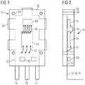
- Fig. 1 is an angle sensor module 10 for a housing cover (see Fig. 5 and 8th ).
- the angle sensor module 10 has a leadframe 12 with free contact ends 14, 16, 18, which serve as electrical contacts for connection to another leadframe in the housing cover, which also has a customer connector 20 (see FIG Fig. 5 and 6 ), which can be configured according to customer requirements.
- the three electrical contacts 14, 16, 18 of the leadframe 12 are connected via bonded electrical connections 22 with a circuit 24 directly, which is an evaluation electronics for a transducer 26.
- the transducer 26, which may be formed, for example, as a magnetoresistive sensor or as a Hall sensor is in turn connected via bonded leads 28 to the evaluation electronics 24.
- capacitors 30 are provided between the contacts 14, 16, 18, which improve the electromagnetic compatibility of the angle sensor module 10.
- the leadframe 12 with the contacted electrical components 24, 26, 30 is overmolded or encapsulated with a thermoset 32, which makes the angle sensor module insensitive to external influences.
- the illustrated angle sensor module 10 is finally used in a housing cover, wherein the positioning can be done via holes 34 or by stop edges 36 of the lead frame itself. This will be related later Fig. 5 and 6 discussed in more detail.
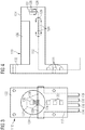
- thermoset coating 132 is firstly produced around a leadframe 112 with electrically connected electronic components 124, 126, 130, and then the angle sensor module is inserted into the housing cover.
- This in Fig. 3 shown angle sensor module has a redundant sensor with two sensors 126 which are arranged parallel to each other on both sides of an end 127 of a Z-shaped angled lead frame 112.
- the transducers 126 are connected by connections 128 not directly associated with evaluation electronics 124, but via traces of the lead frame, which then are in turn connected via connections 129 to the evaluation circuits 124.
- Due to the here Z-shaped design of the lead frame 112 is formed after encapsulation with the thermoset 132, a cylindrical dome 134 which has partially rib-shaped recesses 136. With this design, it is possible to arrange both transducers 126 in a homogeneous magnetic field, which is formed by the projection 134 surrounding magnetic elements.
- the angle sensor module 110 has four connection contacts 114, 116, 118, 119, which in turn are angled. Since at the in 3 and 4 shown angle sensor module 110 two output channels are provided, three capacitors 130 are necessary to improve the electromagnetic compatibility.
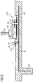
- Fig. 5 shows in cross section a housing cover 11 having a recess 40 in which an angle sensor module 210 is inserted.
- the housing cover 11 has a second leadframe 42, which is encapsulated to form the housing with thermoplastic or thermosetting plastic.
- the second leadframe 42 forms a custom-designed connector 20 to which, for example, a plug for connection to the control unit of a motor can be connected.
- the leadframe On the opposite inside of the housing, the leadframe has electrical contact terminals 44, 45, 47 which serve for connection to the electrical terminals 14, 16, 18 of the angle sensor module 10.
- Is shown in Fig. 5 also a rotary magnet 46 which sits on a shaft 48 of an actuator (not shown) and whose angular position can be detected by means of the angle sensor module.
- the transducer 26 is at the here and in Fig. 6 shown angle sensor module 210 positioned according to the position of the rotary magnet 46.
- connection of the previously described angle sensor module 210 to the housing cover 11 is effected by simple pressing, wherein in the contact region between the electrical terminals 214, 216, 218 of the angle sensor module 210 and the electrical contact terminals 44, 45, 47 of the second leadframe 42 of the housing cover 11 known plug-in connections 50 are provided in which spring tongues 52 abut sharp contact with the contact. Since such connectors ensure their strong clamping and a good and accurate mechanical support, skilful dimensioning can be dispensed with further attachment measures, the positioning can be done via dowel pins (not shown) on the plastic housing of the housing cover 11, in the holes 34 of Angle sensor module 210 (see also Fig. 1 and 2 ) intervene. To improve the hold and avoid displacement of the angle sensor module at, for example, high accelerations, an adhesive layer 54 may be provided between the angle sensor module 210 and the housing cover 11.
- a further embodiment of an angle sensor module 310 is shown, in which the leadframe 312 in the region of the transducer 26 is embossed trapezoidal, so that it is closer to the rotary magnet 46, ie the thermoset layer between the magnet 46 and the sensor is minimized, thereby results in a better measurement accuracy and the use of smaller magnets is made possible.
- the arrangement of the evaluation electronics 24 and the capacitor 30 corresponds to the in Fig. 6 shown embodiment.
- Fig. 8 again shows a housing cover 11, which is substantially the in Fig. 5 shown housing cover, wherein only the electrical contact terminals 44, 45, 47 are directly adjacent to each other and should not serve the mechanical fixation of the angle sensor module.
- the electrical connection between the terminal lugs 14, 16, 18 of the angle sensor module and the electrical contact terminals 44, 45, 47 takes place here by welding, while the support of the angle sensor module 10, that of the embodiment according to FIG Fig. 1 corresponds to the housing cover 11 is effected primarily by the adhesive layer 54.
- the positioning is again carried out with the aid of the bores 34 and the dowel pins (not shown) assigned to the housing cover 11 or with the aid of a clamping and / or latching connection between the angle sensor module and the housing cover.
Description
- Die vorliegende Erfindung befasst sich mit einem Verfahren zur Herstellung eines Trägerelements, beispielsweise in der Form eines Gehäusedeckels oder zum Einsetzen in einen Gehäusedeckel, mit einem Winkelsensor zur Erfassung des Drehwinkels einer Welle und mit elektrischen Steckanschlüssen, wobei das Trägerelement aus Kunststoff, z. B. Duroplast oder Thermoplast besteht und elektrische Bauteile mit einem Kunststoff umspritzt oder umgossen werden. Gegenstand der vorliegenden Erfindung ist auch ein Trägerelement mit einem Winkelsensor für einen Aktuator einer Verbrennungskraft-Maschine, wobei der Winkelsensor einen dem Aktuator zugeordneten Magneten und elektronische Bauteile umfasst und mit elektrischen Steckanschlüssen, z. B. einem so genannten Kundenstecker, ausgerüstet ist.
- Derartige Trägerelemente mit integriertem Winkelsensor finden bei Verbrennungskraftmaschinen Anwendung, wo sie die Drehstellung von Aktuatoren für die Steuerung des Verbrennungsmotors erfassen, beispielsweise bei der Laststeuerung, Abgasrückführung, Luftklappen im Ansaugtrakt oder der Verstellung der Schaufeln eines Turboladers. Die Ausbildung als Gehäusedeckel hat den Vorteil, dass der Winkelsensor selbst in einer Baueinheit geschützt verschlossen wird, wobei die elektrischen Anschlüsse als Kundenstecker ausgebildet sind, der nach Kundenwünschen konfiguriert ist und den elektrischen Anschluss an die Motorelektronik ermöglicht.
- Der eigentliche Winkelsensor besteht dabei in der Regel aus wenigstens einem magnetoresistiven Messaufnehmer oder einem Hallsensor, z. B. in Halbleitertechnik, wobei dem Messaufnehmer auch bereits jeweils ein Chip mit der Auswerteelektronik zugeordnet ist. Häufig umfasst der Winkelsensor auch noch Kondensatoren, um die elektromagnetische Verträglichkeit zu verbessern. Vorteilhaft ist die redundante Ausbildung mit zwei Messaufnehmern und zwei zugeordneten Auswertelektroniken, um die Sicherheit beispielsweise beim Erfassen der Drehwinkelstellung einer Drosselklappe (E-Gas) zu erhöhen.
- Die Herstellung z. B. von Gehäusedeckeln mit integriertem Winkelsensor erfolgt bislang in der Weise, dass der Messaufnehmer und die Auswerteelektronik von einem Chip-Hersteller vorkonfiguriert wird, d. h., der Chip für die Auswerteelektronik und der Messaufnehmer werden mit einem Stanzgitter zur Kontaktierung nach außen elektrisch verbunden, beispielsweise durch Bonden, und anschließend werden die elektronischen Bauteile mit einem Duroplasten einzeln umspritzt. Anschließend erfolgt eine Prüfung durch den Hersteller und der vorkonfigurierte Winkelsensor wird dann an einen Kunden geliefert. Dieser bezieht von einem weiteren Hersteller einen Gehäusedeckelrohling aus Kunststoff, der in der Regel im Spritzgussverfahren hergestellt wird, und stellt das Winkelsensor-Winkelsensormodul dadurch her, dass zunächst der vorkonfigurierte Winkelsensor mit einem so genannten Leadframe elektrisch durch Schweißen oder Löten verbunden wird. Anschließend wird der Leadframe in den Gehäuserohling eingelegt und der Leadframe mit einem Thermoplasten umspritzt, wobei eine separate Abdeckung die Sensorik schützen muss, weil diese sonst beschädigt würde. Abschließend muss nochmals eine Funktionskontrolle des fertigen Gehäusedeckels vorgenommen werden.
- Zusammenfassend lässt sich das bisherige Herstellungsverfahren durch drei Spritzgießvorgänge charakterisieren, wobei sowohl das teilweise Umspritzen des Stanzgitters auf Seiten des Chip-Herstellers als auch das abschließende Umspritzen des Leadframes zur Verbindung mit dem Gehäusedeckel unter besonderen Prozessbedingungen stattfinden muss, um die Gefahr von Funktionsstörungen zu vermeiden. Schließlich sind auch zwei Funktionsüberprüfungen notwendig, nämlich auf Seiten des Chipherstellers nach Fertigstellung des Sensors und auf Seiten des Herstellers des Trägerelements nach dem Umspritzen des Leadframes.
- Das Festlegen des eigentlichen Winkelsensors an dem Trägerelement durch Umspritzen führt auch zwangsläufig dazu, dass der Messaufnehmer von dem zu erfassenden Drehmagneten durch wenigstens zwei Kunststoffwandungen oder -schichten getrennt ist. Der daraus resultierende größere Abstand verschlechtert die Messgenauigkeit und erfordert stärkere Magneten.
- Aus der
DE 196 18 631 A1 ist eine Vorrichtung zur Messung von Dreh- oder Winkelbewegungen und ein Verfahren zur Herstellung dieser Vorrichtung bekannt. Ein Messwertaufnehmer enthält hierzu eingeschlossen in ein Gehäuse die zum Erzeugen des elektrischen Signals vorgesehenen Bauteile. Über ein Anschlusskabel werden die Signale aus dem Gehäuse herausgeführt. Dabei besteht das Gehäuse aus zwei Halbschalen, die aus Kunststoff gefertigt sind und die nach dem Einfügen der elektrischen Bauteile und Einlegen des Anschlusskabels durch Kleben oder Verschweißen verbunden sind. Der Innenraum der beiden verbundenen Halbschalen ist mit einem Heißschmelzkleber ausgefüllt. - Aus der
DE 41 15 883 A1 ist ein Verfahren zum Herstellen eines Gussteils mit darin eingebetteten Elektroden bekannt. - Die
DE 1 275 939 A2 ,US 5 637 995 A ,EP 1 669 573 A2 und dieWO 03/006805 A1 - Aus der
WO 2006/024626 A2 ist eine elektrische Baugruppe mit einer integrierten Schaltung bekannt, die mindestens einen Leistungshalbleiterelement und weitere elektronische Bauteile aufweist, die durch von einem Betablech gebildete Leiter miteinander und mit Anschlüssen verbunden sind. - Aus der
DE 100 54 123 A1 ist ein Drehwinkelerfasser mit einer Sensorabdeckung bekannt, durch die ein Magnetsensorelement und ein Außenverbindungsanschluss einstückig gestaltet sind. - Die Aufgabe der vorliegenden Erfindung besteht darin, ein Verfahren zur Herstellung eines Gehäusedeckels oder sonstigen Trägerelements mit einem Winkelsensor der vorstehend beschriebenen Art anzugeben, das gegenüber den bekannten Herstellungsverfahren vereinfacht ist.
- Erfindungsgemäß ist daher vorgesehen, dass die elektronischen Bauteile des Winkelsensors unmittelbar mit einem Leadframe elektrisch verbunden werden, der Leadframe ohne das Trägerelement mit den elektronischen Bauelementen mit einem Duroplasten zur Bildung eines Winkelsensormoduls umspritzt oder umgossen wird und das Winkelsensormodul schließlich in eine Aufnahme des Trägerelements eingelegt, befestigt und mit den elektrischen Anschlüssen verbunden wird.
- Das Verfahren hat den Vorteil, dass nur noch zwei Spritzgießvorgänge durchgeführt werden müssen, wobei das bislang vorab vorgesehene teilweise Umspritzen eines mit Bauelementen bestückten Stanzgitters entfällt und die elektronischen Bauelemente des Winkelsensors unmittelbar mit dem Leadframe elektrisch verbunden werden. Dadurch reduziert sich die Anzahl der innerhalb des Winkelsensormoduls vorzusehenden elektrischen Verbindungen und das Risiko eines Funktionsausfalls wird vermindert. Vorteilhaft in diesem Zusammenhang ist auch, dass nach dem Umspritzen mit Duroplast nur eine einzige Funktionskontrolle durchzuführen ist.
- Die elektronischen Bauelemente sind beispielsweise wenigstens ein Messaufnehmer und wenigstens eine einem Messaufnehmer zugeordnete Auswertelektronik, wobei als weitere Bauelemente Kondensatoren zur Verbesserung der elektromagnetischen Verträglichkeit mit dem Leadframe verbunden sind. Während für das Umspritzen des Leadframes mit den empfindlichen elektronischen Bauelementen und den beispielsweise durch Bonden, Löten oder Leitkleben hergestellten elektrischen Verbindungen vornehmlich Duroplast geeignet ist, kann das Trägerelement selbst auch aus anderen Kunststoffen bestehen, beispielsweise spritzgegossenem Thermoplast.
- Eine bevorzugte Weiterbildung des Verfahrens kann vorsehen, dass der Leadframe durch unmittelbare Anlage an definierten Stellen an dem Trägerelement bzw. in dem Gehäusedeckel positioniert wird. Hierdurch lässt sich eine optimale Lage der Messaufnehmer in dem Gehäusedeckel ohne Toleranzeinflüsse durch den Kunststoff erreichen, die allerdings auch durch andere Maßnahmen sichergestellt werden kann.
- Zur Bildung eines redundanten Systems mit wenigstens zwei Messaufnehmern wird vorgeschlagen, den Leadframe beispielsweise Z-förmig oder L-förmig umzubiegen, wobei an dem in das Gehäuseinnere ragenden Ende des Leadframes auf jeder Seite jeweils ein Messaufnehmer oder zwei Messaufnehmer nebeneinander elektrisch verbunden werden und der nach innen ragende Bereich des Leadframes vollständig mit Duroplast umspritzt wird. Diese Ausbildung stellt sicher, dass beide Messaufnehmer in einem rotierenden, homogenen Magnetfeld angeordnet werden können, so dass sie im Wesentlichen identische Ausgangssignale erzeugen. Um unnötige Materialansammlungen zu vermeiden, die insbesondere wegen der höheren thermisch relevanten Masse bei Temperaturkalibrierungen eine längere Wartezeit bedeutet, können im Bereich der Umspritzung des in das Gehäuse ragenden Bereiches rippenförmige Aussparungen vorgesehen werden.
- Die elektrische Verbindung zwischen dem Winkelsensormodul und dem Trägerelement kann über Schweißverbindungen oder eine Steckverbindungen mit Klemmwirkung erfolgen, die auch einen mechanischen Halt gewährleisten können. Der mechanische Halt zwischen dem Winkelsensormodul und dem Gehäusedeckel kann auch durch Verkleben oder Verklipsen erreicht oder verbessert werden.
- Gegenstand der vorliegenden Erfindung ist auch ein Trägerelement mit einem Winkelsensor für einen Aktuator einer Verbrennungskraftmaschine, der nach einem der vorstehend beschriebenen Verfahren vorgestellt worden ist. Der Winkelsensor umfasst einen auf einer Welle des Aktuators sitzenden, in einem Gehäuse rotierenden Drehmagneten und elektronische Bauteile sowie elektrische Anschlüsse. Ein solches Trägerelement besteht selbst aus einem Kunststoff, wie z. B. Duro- oder Thermoplast, mit dem ein separates Winkelsensormodul mechanisch und elektrisch verbunden ist, wobei das Winkelsensormodul einen Leadframe aufweist, der mit elektrischen Bauteilen des Winkelsensors verbunden ist, und der Leadframe mit den elektronischen Bauteilen getrennt von dem Trägerelement mit einem Duroplasten umspritzt oder umgossen sind, der Leadframe des Winkelsensormoduls in den Bereich zwischen dem wenigstens einen Messaufnehmer und der Auswertschaltung elektrisch isolierend vollständig von Duroplast umgeben ist und der wenigstens eine Messwertaufnehmer nur eine einzige Schicht aus Duroplast als Zwischenwand zu dem Drehmagnet aufweist. Die elektronischen Bauteile bestehen aus dem wenigstens einen Messaufnehmer und auch aus einer Auswertschaltung für das entsprechende Messaufnehmersignal. Als Messaufnehmer sind magnetisch basierte Messaufnehmer mit magnetoresistiven Eigenschaften oder mit wenigstens einem Hall-Element vorgesehen. Zur Verbesserung der elektromagnetischen Verträglichkeit ist der Leadframe mit wenigstens einem Kondensator elektrisch verbunden, der ebenfalls mit Duroplast umspritzt ist.
- Ein großer Vorteil des beschriebenen Gehäusedeckels mit integriertem Winkelsensor besteht auch darin, dass der wenigstens eine Messaufnehmer nur mit einer einzigen Schicht aus Kunststoff überzogen ist. Dadurch lässt sich die Spaltbreite zwischen Messaufnehmer und bewegtem Magnetelement gegenüber zwei Kunststoffschichten, wie sie beim Stand der Technik anzutreffen sind, verringern, da fertigungstechnisch nur bestimmte Mindestschichtdicken bei Spritzgießvorgängen einzuhalten sind. Der Leadframe kann im Bereich des wenigstens einen Messwertaufnehmers ausgestellt sein, so dass dieser möglichst nahe an die Oberfläche innerhalb der Duroplastmasse heranreicht.
- Das elektrisch isolierende Umschließen der Verbindungsbereiche des Leadframe zwischen dem Messwertaufnehmer der Auswertschaltung erlaubt das unmittelbare Befestigen des Winkelsensormoduls an dem Trägerelement ohne nachträgliches Isolieren, da die Leiter nicht durch Schmutzpartikel kurzgeschlossen werden können.
- Eine redundante Sensorik lässt sich bei dem Winkelsensor-Winkelsensormodul z. B. dadurch realisieren, dass zwei Messaufnehmer parallel zueinander auf beiden Seiten des Leadframes oder nebeneinander angeordnet und jeweils mit einer getrennten oder gemeinsamen Auswertelektronik verbunden sind. Damit beide Messaufnehmer mit gleichen Magnetfeldern zusammenwirken können, ist es bevorzugt, dass die beiden parallel zueinander liegenden Messaufnehmer parallel zur Stirnfläche eines Domes aus Duroplast in diesem angeordnet sind, wobei der Leadframe Z-förmig oder L-förmig in diesen Vorsprung hineinragt.
- Zur Vermeidung von Materialansammlungen kann der Duroplast im Bereich des Domes rippenförmige Aussparungen aufweisen.
- Nachfolgend wird anhand der beigefügten Zeichnungen näher auf Ausführungsbeispiele der Erfindung eingegangen. Es zeigen:
- Fig. 1
- eine schematische Darstellung eines Winkelsensormoduls für einen Gehäusedeckel;
- Fig. 2
- einen schematischen Schnitt des Winkelsensormoduls aus
Fig.1 ; - Fig. 3
- eine schematische Ansicht eines Winkelsensormoduls für einen Gehäusedeckel mit redundanter Sensorik;
- Fig. 4
- einen schematischen Schnitt des Winkelsensormoduls aus
Fig.3 . - Fig. 5
- einen schematischen Teilschnitt eines Gehäusedecke mit einem eingesteckten Winkelsensormodul nach
Fig. 6 ; - Fig. 6
- eine schematische Draufsicht auf das Winkelsensormodul aus
Fig. 5 ; - Fig. 7
- einen schematischen schnitt einer weiteren Ausführungsform eines Winkelsensormoduls;
- Fig. 8
- einen schematischen Teilschnitt eines Gehäusedeckels mit einem eingeklebten Winkelsensormodul nach
Fig. 1 mit verschweißten elektrischen Kontakten. - In
Fig. 1 ist ein Winkelsensormodul 10 für einen Gehäusedeckel (sieheFig. 5 und8 ) dargestellt. Das Winkelsensormodul 10 besitzt einen Leadframe 12 mit freien Kontaktenden 14, 16, 18, welche als elektrische Kontakte zur Verbindung mit einem weiteren Leadframe in dem Gehäusedeckel dienen, der auch einen Kundenstecker 20 (sieheFig. 5 und6 ) bildet, der nach Kundenwünschen konfiguriert werden kann. Die drei elektrischen Kontakte 14, 16, 18 des Leadframes 12 sind über gebondete elektrische Verbindungen 22 mit einer Schaltung 24 unmittelbar verbunden, die eine Auswertelektronik für einen Messwertaufnehmer 26 darstellt. Der Messwertaufnehmer 26, der beispielsweise als magnetoresistiver Sensor oder als Hallsensor ausgebildet sein kann, ist wiederum über gebondete Zuleitungen 28 mit der Auswertelektronik 24 verbunden. Zudem sind zwischen den Kontakten 14, 16, 18 Kondensatoren 30 vorgesehen, die die elektromagnetische Verträglichkeit des Winkelsensormoduls 10 verbessern. - Der Leadframe 12 mit den kontaktierten elektrischen Bauelementen 24, 26, 30 ist mit einem Duroplast 32 überspritzt oder umgossen, der das Winkelsensormodul unempfindlich gegen äußere Einflüsse macht.
- Das gezeigte Winkelsensormodul 10 wird abschließend in einen Gehäusedeckel eingesetzt, wobei die Positionierung über Bohrungen 34 oder auch durch Anschlagkanten 36 des Leadframes selbst erfolgen kann. Hiermit wird später im Zusammenhang mit
Fig. 5 und6 noch näher eingegangen. - Ein redundantes Winkelsensormodul 110 ist in
Fig. 3 und Fig. 4 gezeigt. Bei diesem Winkelsensormodul wird wiederum zunächst der Duroplastüberzug 132 um einen Leadframe 112 mit elektrisch verbundenen elektronischen Bauelementen 124, 126, 130 erzeugt und anschließend wird das Winkelsensormodul in den Gehäusedeckel eingesetzt. - Das in
Fig. 3 gezeigte Winkelsensormodul verfügt über eine redundante Sensorik mit zwei Messaufnehmern 126, die parallel zueinander auf beiden Seiten eines Endes 127 eines Z-förmig abgewinkelten Leadframes 112 angeordnet sind. Die Messwertaufnehmer 126 sind durch Verbindungen 128 nicht unmittelbar mit zugeordneten Auswertelektroniken 124 verbunden, sondern über Leiterbahnen des Leadframes, die dann wiederum über Verbindungen 129 mit den Auswertschaltungen 124 verbunden sind. Bedingt durch die hier Z-förmige Ausbildung des Leadframes 112 entsteht nach dem Umspritzen mit dem Duroplasten 132 ein zylindrischer Dom 134, der teilweise rippenförmige Aussparungen 136 aufweist. Durch diese Ausbildung ist es möglich, beide Messwertaufnehmer 126 in einem homogenen Magnetfeld anzuordnen, das durch den Vorsprung 134 umgebende Magnetelemente gebildet ist. Entsprechend den zwei Ausgangskanälen der beiden Messwertaufnehmer 126 verfügt das Winkelsensormodul 110 über vier Anschlusskontakte 114, 116, 118, 119, die wiederum abgewinkelt sind. Da bei dem inFig. 3 und 4 gezeigten Winkelsensormodul 110 zwei Ausgangskanäle vorgesehen sind, sind drei Kondensatoren 130 notwendig, um die elektromagnetische Verträglichkeit zu verbessern. -
Fig. 5 zeigt im Querschnitt einen Gehäusedeckel 11, der eine Ausnehmung 40 aufweist, in welcher ein Winkelsensormodul 210 eingesetzt ist. Der Gehäusedeckel 11 besitzt einen zweiten Leadframe 42, der zur Bildung des Gehäuses mit Thermoplast oder Duroplast umspritzt ist. Der zweite Leadframe 42 bildet eine nach Kundenwünschen ausgebildete Steckverbindung 20, an die beispielsweise ein Stecker zur Verbindung mit dem Steuergerät eines Motors angeschlossen werden kann. Auf der gegenüberliegenden Gehäuseinnenseite verfügt der Leadframe über elektrische Kontaktanschlüsse 44, 45, 47 die zur Verbindung mit den elektrischen Anschlüssen 14, 16, 18 des Winkelsensormoduls 10 dienen. Dargestellt ist inFig. 5 auch ein Drehmagnet 46, der auf eine Welle 48 eines Aktuators (nicht gezeigt) sitzt und dessen Drehwinkelstellung mit Hilfe des Winkelsensormoduls erfasst werden kann. Der Messwertaufnehmer 26 ist bei dem hier und inFig. 6 gezeigten Winkelsensormodul 210 entsprechend der Lage des Drehmagnetes 46 positioniert. - Die Verbindung des zuvor beschriebenen Winkelsensormoduls 210 mit dem Gehäusedeckel 11 erfolgt durch einfaches Aufpressen, wobei im Kontaktbereich zwischen den elektrischen Anschlüssen 214, 216, 218 des Winkelsensormoduls 210 und den elektrischen Kontaktanschlüssen 44, 45, 47 des zweiten Leadframes 42 des Gehäusedeckels 11 vom Grundprinzip her bekannte Steckverbindungen 50 vorgesehen sind, bei welchen Federzungen 52 scharfkantig am Kontaktpartner anliegen. Da solche Steckverbindungen durch ihre starke Klemmung auch einen guten und genauen mechanischen Halt gewährleisten, kann bei geschickter Dimensionierung auf weitergehende Befestigungsmaßnahmen verzichtet werden, wobei die Positionierung über Passstifte (nicht gezeigt) an dem Kunststoffgehäuse des Gehäusedeckels 11 erfolgen kann, die in die Bohrungen 34 des Winkelsensormoduls 210 (siehe hierzu auch
Fig. 1 und 2 ) eingreifen. Zur Verbesserung des Halts und Vermeidung einer Verlagerung des Winkelsensormoduls bei beispielsweise hohen Beschleunigungen, kann zwischen dem Winkelsensormodul 210 und dem Gehäusedeckel 11 eine Klebeschicht 54 vorgesehen sein. - In
Fig. 7 ist eine weitere Ausführungsform eines Winkelsensormoduls 310 gezeigt, bei welcher der Leadframe 312 im Bereich des Messwertaufnehmers 26 durch Prägen trapezförmig ausgestellt ist, so dass dieser näher an dem Drehmagneten 46 liegt, d. h. die Duroplastschicht zwischen dem Magneten 46 und dem Messaufnehmer ist minimiert, wodurch sich eine bessere Messgenauigkeit ergibt und der Einsatz kleinerer Magnete ermöglicht wird. Die Anordnung der Auswertelektronik 24 und des Kondensators 30 entspricht der inFig. 6 gezeigten Ausführungsform. -
Fig. 8 zeigt wiederum einen Gehäusedeckel 11, der im Wesentlichen dem inFig. 5 gezeigten Gehäusedeckel entspricht, wobei lediglich die elektrischen Kontaktanschlüsse 44, 45, 47 unmittelbar nebeneinander liegen und nicht der mechanischen Fixierung des Winkelsensormoduls dienen sollen. Die elektrische Verbindung zwischen den Anschlusslaschen 14, 16, 18 des Winkelsensormoduls und den elektrischen Kontaktanschlüssen 44, 45, 47 erfolgt hier durch ein Verschweißen, während der Halt des Winkelsensormoduls 10, das der Ausführungsform gemäßFig. 1 entspricht, an dem Gehäusedeckel 11 in erster Linie durch die Klebeschicht 54 bewirkt wird. Die Positionierung erfolgt wiederum mit Hilfe der Bohrungen 34 und den nicht gezeigten, dem Gehäusedeckel 11 zugeordneten Passstiften oder mit Hilfe einer Klemm- und/oder Rastverbindung zwischen dem Winkelsensormodul und dem Gehäusedeckel.
Claims (15)
- Verfahren zur Herstellung eines Trägerelements (11) mit einem Winkelsensor (10) für einen Aktuator einer Verbrennungskraftmaschine zur Erfassung des Drehwinkels einer Welle (48) und mit elektrischen Steckanschlüssen (20), wobei das Trägerelement aus Kunststoff besteht und elektronische Bauteile (12, 24, 26, 30) des Winkelsensors mit einem Kunststoff umspritzt oder umgossen werden,
wobei der Winkelsensor (10) elektronische Bauteile (12, 24, 26, 30) mit wenigstens einem Messwertaufnehmer (26), der zum Erfassen der Stellung eines auf einer Welle (48) des Aktuators sitzenden und drehbeweglichen Magneten (46) ausgebildet ist, einer Auswertschaltung (24) zur Auswertung des entsprechenden Messwertaufnehmer-Signals und Kondensatoren (30) zur Verbesserung der elektromagnetischen Verträglichkeit umfasst,
wobei als elektronische Bauelemente des Winkelsensors (10) wenigstens der Messwertaufnehmer (26), wenigstens die dem Messwertaufnehmer (26) zugeordnete Auswertschaltung (24) und die Kondensatoren (30) unmittelbar mit einem Leadframe (12) elektrisch verbunden werden,
wobei der Leadframe (12) mit den elektrisch verbundenen Bauelementen (24, 26, 30) derart mit einem Duroplast (32) zur Bildung eines Winkelsensormoduls (10) umspritzt oder umgossen wird, dass der wenigstens eine Messwertaufnehmer (26) nur eine einzige Schicht aus Duroplast als Zwischenwand zum Magneten (46) aufweist, wobei das Winkelsensormodul (10) schließlich in eine Aufnahme (40) des Trägerelements (11) eingelegt, befestigt und mit den Steckanschlüssen (20) anschließend verbunden wird,
wobei das Trägerelement (11) als Gehäusedeckel aus Duroplast oder Thermoplast mit den Steckanschlüssen (20) spritzgegossen wird. - Verfahren nach Anspruch 1, wobei die Kontaktierung der Bauelemente (24, 26, 30) durch Bonden, Löten und/oder Leitkleben erfolgt.
- Verfahren nach einem der vorhergehenden Ansprüche,
wobei der Leadframe (12) durch unmittelbare Anlage an definierten Stellen an dem Trägerelement bzw. in dem Gehäusedeckel positioniert wird. - Verfahren nach einem der vorhergehenden Ansprüche,
wobei der Leadframe (112) Z-förmig oder L-förmig umgebogen wird, wobei mit dem in das Gehäuseinnere ragenden Ende (127) des Leadframes (112) auf jeder Seite jeweils ein Messaufnehmer (126) oder zwei Messaufnehmer seitlich nebeneinander elektrisch verbunden werden und der nach innen ragende Bereich des Leadframes (112) vollständig mit Duroplast umspritzt oder umgossen wird. - Verfahren nach Anspruch 4, wobei der Duroplast im Bereich des Domes (134) rippenartig ausgespart wird.
- Verfahren nach einem der vorhergehenden Ansprüche,
wobei das Winkelsensormodul (10) mit dem Trägerelement (11) über Steckverbindungen (50) mit Klemmwirkung mechanisch und/oder elektrisch verbunden wird. - Verfahren nach einem der Ansprüche 1 bis 5, wobei der Leadframe des Winkelsensormoduls (10) über eine Löt- oder Schweißverbindung elektrisch mit dem Leadframe (42) des Trägerelements (11) verbunden wird.
- Verfahren nach einem der vorhergehenden Ansprüche,
wobei das Winkelsensormodul (10) mit dem Trägerelement (11) verklebt wird. - Trägerelement (11) mit einem Winkelsensor (10) für einen Aktuator einer Verbrennungskraftmaschine, wobei der Winkelsensor elektronische Bauteile (24 ,26 ,30) mit wenigstens einem Messwertaufnehmer (26), der zum Erfassen der Stellung eines auf einer Welle (48) des Aktuators sitzenden und drehbeweglichen Magneten (46) ausgebildet ist, und einer Auswertschaltung (24) zur Auswertung des entsprechenden Messaufnehmer-Signals umfasst und mit elektrischen Steckanschlüssen(20) ausgerüstet ist,
wobei das Trägerelement (11) selbst aus Kunststoff gefertigt ist und mit dem Trägerelement ein separates Winkelsensormodul (10) mechanisch und elektrisch verbunden ist, wobei das Winkelsensormodul (10) einen Leadframe (12) aufweist, der mit elektrischen Bauelementen (24, 26, 30) des Winkelsensors verbunden ist, und der Leadframe (12) mit den elektronischen Bauelementen (24, 26, 30) getrennt von dem Trägerelement mit Duroplast (32) umspritzt oder umgossen sind, wobei der Leadframe (12) des Winkelsensormoduls in dem Bereich zwischen dem wenigstens einen Messwertaufnehmer (26) und der Auswertschaltung (24) elektrisch isolierend vollständig von Duroplast (32) umgeben ist und der wenigstens eine Messwertaufnehmer (26) nur eine einzige Schicht aus Duroplast als Zwischenwand zum Magneten (46) aufweist,
wobei das Trägerelement (11) als Gehäusedeckel aus Duroplast oder Thermoplast mit den Steckanschlüssen (20) mittels Spritzgießens ausgebildet ist, und
wobei mit dem Leadframe wenigstens ein Kondensator (30) elektrisch verbunden ist, der ebenfalls im Winkelsensormodul (10) umspritzt ist. - Trägerelement nach Anspruch 9, wobei der wenigstens eine Messwertaufnehmer (26) als magnetisch basierter Messwertaufnehmer mit magnetoresistiven Elementen oder mit wenigstens einem Hall-Element ausgebildet ist.
- Trägerelement nach einem der Ansprüche 9 bis 10,
wobei zwei Messwertaufnehmer (126) parallel zueinander auf beiden Seiten des Leadframes (112) oder zwei Messwertaufnehmer nebeneinander auf einer Seite des Leadframes angeordnet und mit mindestens einer Auswertelektronik elektrisch (124) verbunden sind. - Trägerelement nach Anspruch 11, wobei die beiden Messwertaufnehmer (126) parallel zur Stirnfläche eines zylindrischen Domes (134) aus Duroplast in diesem angeordnet sind, wobei der Leadframe (12) in diesen Vorsprung (134) hineinragt.
- Trägerelement nach Anspruch 12, wobei der Dom (134) rippenartige Aussparungen (136) aufweist.
- Trägerelement nach einem der Ansprüche 9 bis 13,
wobei der Leadframe (12) im Bereich des Messwertaufnehmers (26) durch eine trapezförmige Biegung oder Prägung (312) so ausgebildet ist, dass die Kunststoffwandstärke im Bereich des Messwertaufnehmers minimiert ist. - Trägerelement nach einem der Ansprüche 9 bis 14,
wobei zwischen einem Leadframe (42) des Trägerelements und dem Winkelsensormodul (10) elektrische Steckverbindungen vorgesehen sind.
Applications Claiming Priority (2)
| Application Number | Priority Date | Filing Date | Title |
|---|---|---|---|
| DE102006046984A DE102006046984A1 (de) | 2006-10-04 | 2006-10-04 | Verfahren zur Herstellung eines Trägerelements mit einem Winkelsensor |
| PCT/EP2007/060291 WO2008040680A1 (de) | 2006-10-04 | 2007-09-28 | Verfahren zur herstellung eines trägerelements mit einem winkelsensor |
Publications (2)
| Publication Number | Publication Date |
|---|---|
| EP2087320A1 EP2087320A1 (de) | 2009-08-12 |
| EP2087320B1 true EP2087320B1 (de) | 2019-11-06 |
Family
ID=38695470
Family Applications (1)
| Application Number | Title | Priority Date | Filing Date |
|---|---|---|---|
| EP07820678.6A Active EP2087320B1 (de) | 2006-10-04 | 2007-09-28 | Verfahren zur herstellung eines trägerelements mit einem winkelsensor |
Country Status (7)
| Country | Link |
|---|---|
| US (1) | US8339124B2 (de) |
| EP (1) | EP2087320B1 (de) |
| JP (1) | JP5135351B2 (de) |
| KR (1) | KR101503935B1 (de) |
| CN (1) | CN101558285B (de) |
| DE (1) | DE102006046984A1 (de) |
| WO (1) | WO2008040680A1 (de) |
Families Citing this family (18)
| Publication number | Priority date | Publication date | Assignee | Title |
|---|---|---|---|---|
| DE102009006529A1 (de) | 2009-01-28 | 2010-08-26 | Continental Automotive Gmbh | Positionssensor |
| US8901921B2 (en) * | 2009-11-25 | 2014-12-02 | Infineon Technologies Ag | Angle measurement system for determining an angular position of a rotating shaft |
| DE102010047128A1 (de) * | 2010-09-30 | 2012-04-05 | Infineon Technologies Ag | Hallsensoranordnung zum redundanten Messen eines Magnetfeldes |
| DE102012215091A1 (de) * | 2011-08-24 | 2013-02-28 | Continental Teves Ag & Co. Ohg | Sensor mit einem einzigen elektrischen Trägermittel |
| DE102011118773B4 (de) | 2011-11-17 | 2023-10-05 | Hartmann-Exact Gmbh | Vorrichtung zur berührungslosen Erfassung der Relativposition zweier relativ zueinander bewegbarer Teile |
| DE102012224075A1 (de) | 2012-12-20 | 2014-06-26 | Continental Teves Ag & Co. Ohg | Sensor zum Erfassen einer Position eines Geberelements |
| DE102013213054A1 (de) * | 2013-07-04 | 2015-01-08 | Continental Automotive Gmbh | Drehwinkelsensorvorrichtung mit redundanten Sensoreinheiten zum Bestimmen eines eindeutigen Winkelsignals |
| DE102013213053A1 (de) * | 2013-07-04 | 2015-01-08 | Continental Automotive Gmbh | Drehwinkelsensorvorrichtung mit redundanten Sensoreinheiten |
| WO2015048953A1 (de) * | 2013-10-02 | 2015-04-09 | Schaeffler Technologies AG & Co. KG | Kolben-zylinder-anordnung |
| JP6017401B2 (ja) * | 2013-11-05 | 2016-11-02 | 愛三工業株式会社 | 回転角度検出センサ |
| SG11201610578WA (en) * | 2014-06-20 | 2017-01-27 | Xcerra Corp | Test socket assembly and related methods |
| DE102014218544A1 (de) | 2014-09-16 | 2016-03-17 | Schaeffler Technologies AG & Co. KG | Sensorikeinheit zur Bestimmung einer Rotorlage eines Elektromotors und ein Elektromotor, vozugsweise für einen Kupplungsaktor eines Kupplungsbetätigungssystems eines Kraftfahrzeuges |
| DE102015207310A1 (de) * | 2015-04-22 | 2016-10-27 | Zf Friedrichshafen Ag | Elektronikmodul und Verfahren zum Umkapseln desselben |
| FR3040213B1 (fr) * | 2015-08-18 | 2017-09-15 | Continental Automotive France | Procede de fabrication d'un capteur de mesure pour vehicule automobile |
| ITUB20160271A1 (it) * | 2016-01-29 | 2017-07-29 | Magneti Marelli Spa | Metodo per l'assemblaggio di un sensore in un componente elettromeccanico per un motore a combustione interna e componente elettromeccanico ottenuto mediante tale metodo |
| US10251295B2 (en) * | 2016-02-01 | 2019-04-02 | Alps Alpine Co., Ltd. | Electronic device and method of producing the same |
| JP2018049942A (ja) * | 2016-09-21 | 2018-03-29 | アイシン精機株式会社 | 変位センサ |
| DE102019210375A1 (de) * | 2019-07-12 | 2021-01-14 | Continental Teves Ag & Co. Ohg | Verfahren zur Herstellung eines robusten Sensors |
Citations (6)
| Publication number | Priority date | Publication date | Assignee | Title |
|---|---|---|---|---|
| US5637995A (en) * | 1992-12-09 | 1997-06-10 | Nippondenso Co., Ltd. | Magnetic detection device having a magnet including a stepped portion for eliminating turbulence at the MR sensor |
| DE10054123A1 (de) * | 1999-11-01 | 2001-05-03 | Denso Corp | Drehwinkelerfasser mit einer Sensorabdeckung, durch die ein Magnetsensorelement und ein Aussenverbindungsanschluss einstückig gestaltet sind |
| WO2003006805A1 (de) * | 2001-07-11 | 2003-01-23 | Siemens Aktiengesellschaft | Verfahren zur berührungslosen erfassung der position einer drosselklappenwelle eines drosselklappenstutzens und drosselklappenstutzen |
| JP2004004114A (ja) * | 1999-11-01 | 2004-01-08 | Denso Corp | 回転角検出装置 |
| WO2006024626A2 (de) * | 2004-08-31 | 2006-03-09 | Siemens Aktiengesellschaft | Elektrische baugruppe |
| EP1669573A2 (de) * | 2004-12-08 | 2006-06-14 | Siemens Aktiengesellschaft | Teileinheit zur betätigung einer drehbar gelagerten welle, deren aktueller drehwinkel kontinuierlich zur erfassen ist |
Family Cites Families (13)
| Publication number | Priority date | Publication date | Assignee | Title |
|---|---|---|---|---|
| JPH0419114A (ja) * | 1990-05-15 | 1992-01-23 | Mitsubishi Electric Corp | インサート電極モールド体の製造方法 |
| DE19618631A1 (de) | 1996-05-09 | 1997-11-13 | Teves Gmbh Alfred | Vorrichtung zur Messung von Dreh- oder Winkelbewegungen und ein Verfahren zur Herstellung dieser Vorrichtung |
| JPH11237395A (ja) * | 1998-02-23 | 1999-08-31 | Honda Motor Co Ltd | 回転センサ及び回転センサ用磁気検出ic |
| JPH11304894A (ja) * | 1998-04-23 | 1999-11-05 | Mitsubishi Electric Corp | 磁気検出装置とその製造方法 |
| US6305921B1 (en) * | 1999-07-12 | 2001-10-23 | Accu-Mold Corp. | Saw tooth mold |
| JP3830319B2 (ja) * | 1999-12-16 | 2006-10-04 | 株式会社デンソー | 回転角度検出センサの温度特性調整方法 |
| DE10133559B4 (de) * | 2001-07-13 | 2005-01-27 | Siemens Ag | Magnetoresistiver Winkelsensor |
| JP4190780B2 (ja) * | 2002-03-18 | 2008-12-03 | 株式会社デンソー | 回転検出装置 |
| JP3720801B2 (ja) * | 2002-10-24 | 2005-11-30 | 三菱電機株式会社 | 磁気検出装置 |
| US7425824B2 (en) * | 2005-05-20 | 2008-09-16 | Honeywell International Inc. | Magnetoresistive sensor |
| US7378721B2 (en) * | 2005-12-05 | 2008-05-27 | Honeywell International Inc. | Chip on lead frame for small package speed sensor |
| US7375406B2 (en) * | 2005-12-20 | 2008-05-20 | Honeywell International Inc. | Thermoplastic overmolding for small package turbocharger speed sensor |
| WO2008112100A2 (en) * | 2007-03-07 | 2008-09-18 | Cts Corporation | Rotary position sensor |
-
2006
- 2006-10-04 DE DE102006046984A patent/DE102006046984A1/de active Pending
-
2007
- 2007-09-28 KR KR1020097009178A patent/KR101503935B1/ko active IP Right Grant
- 2007-09-28 WO PCT/EP2007/060291 patent/WO2008040680A1/de active Application Filing
- 2007-09-28 EP EP07820678.6A patent/EP2087320B1/de active Active
- 2007-09-28 US US12/444,564 patent/US8339124B2/en active Active
- 2007-09-28 JP JP2009530854A patent/JP5135351B2/ja active Active
- 2007-09-28 CN CN2007800373594A patent/CN101558285B/zh active Active
Patent Citations (6)
| Publication number | Priority date | Publication date | Assignee | Title |
|---|---|---|---|---|
| US5637995A (en) * | 1992-12-09 | 1997-06-10 | Nippondenso Co., Ltd. | Magnetic detection device having a magnet including a stepped portion for eliminating turbulence at the MR sensor |
| DE10054123A1 (de) * | 1999-11-01 | 2001-05-03 | Denso Corp | Drehwinkelerfasser mit einer Sensorabdeckung, durch die ein Magnetsensorelement und ein Aussenverbindungsanschluss einstückig gestaltet sind |
| JP2004004114A (ja) * | 1999-11-01 | 2004-01-08 | Denso Corp | 回転角検出装置 |
| WO2003006805A1 (de) * | 2001-07-11 | 2003-01-23 | Siemens Aktiengesellschaft | Verfahren zur berührungslosen erfassung der position einer drosselklappenwelle eines drosselklappenstutzens und drosselklappenstutzen |
| WO2006024626A2 (de) * | 2004-08-31 | 2006-03-09 | Siemens Aktiengesellschaft | Elektrische baugruppe |
| EP1669573A2 (de) * | 2004-12-08 | 2006-06-14 | Siemens Aktiengesellschaft | Teileinheit zur betätigung einer drehbar gelagerten welle, deren aktueller drehwinkel kontinuierlich zur erfassen ist |
Also Published As
| Publication number | Publication date |
|---|---|
| WO2008040680A1 (de) | 2008-04-10 |
| KR20090097849A (ko) | 2009-09-16 |
| US8339124B2 (en) | 2012-12-25 |
| DE102006046984A1 (de) | 2008-04-10 |
| KR101503935B1 (ko) | 2015-03-24 |
| US20100109654A1 (en) | 2010-05-06 |
| CN101558285B (zh) | 2012-11-14 |
| JP2010506157A (ja) | 2010-02-25 |
| CN101558285A (zh) | 2009-10-14 |
| EP2087320A1 (de) | 2009-08-12 |
| JP5135351B2 (ja) | 2013-02-06 |
Similar Documents
| Publication | Publication Date | Title |
|---|---|---|
| EP2087320B1 (de) | Verfahren zur herstellung eines trägerelements mit einem winkelsensor | |
| DE102007054905B4 (de) | Rotationswinkelsensoren und Drosseleinrichtungen | |
| EP2366096B1 (de) | Bausatz für einen elektromotor mit einem drehwinkelgeber | |
| DE4008141C2 (de) | Sensor mit Hall-Effekt | |
| DE202008009002U1 (de) | Magnetfeldsensor | |
| EP2223125B1 (de) | Magnetfeld-sensorelement | |
| DE102011018180A1 (de) | Rotationswinkelsensoren und Herstellungsverfahren dafür | |
| DE102014226483A1 (de) | Positionserfassungseinrichtung | |
| EP1828720B1 (de) | Magnetsensoranordnung | |
| AT411639B (de) | Verfahren zum herstellen einer kunststoffumspritzten leiterstruktur sowie elektrische schaltungseinheit mit einer kunststoffumspritzten leiterstruktur | |
| EP0977979B1 (de) | Verfahren zum herstellen einer sensorbaugruppe sowie sensorbaugruppe | |
| EP2520142B1 (de) | Sensor mit gehäuse und verfahren zu dessen herstellung | |
| DE4219923C2 (de) | Magnet-Sensor | |
| DE19848081A1 (de) | Antriebseinrichtung mit einem Stellantrieb | |
| EP2265102A1 (de) | Sensoraufbau ohne Gehäuse | |
| DE202005013344U1 (de) | Elektrische Moduleinheit und Sensor | |
| EP1546529B1 (de) | Deckel | |
| EP2936515B1 (de) | Verfahren zum herstellen eines messaufnehmers | |
| DE19744673C2 (de) | Vorrichtung zur Erfassung der Drehzahl eines umlaufenden Bauteiles, insbesondere für ein Kraftfahrzeug | |
| DE102011081222B4 (de) | Sensorbaugruppe | |
| WO2008049690A1 (de) | Magnetfeldsensor | |
| WO2011064245A1 (de) | Drehmomentsensor | |
| EP3685124B1 (de) | Halter für eine sensoreinheit | |
| EP2615426A1 (de) | Sensor | |
| DE102021108661A1 (de) | Redundante Sensoreinheit und Verfahren zur Herstellung einer Sensoreinheit |
Legal Events
| Date | Code | Title | Description |
|---|---|---|---|
| PUAI | Public reference made under article 153(3) epc to a published international application that has entered the european phase |
Free format text: ORIGINAL CODE: 0009012 |
|
| 17P | Request for examination filed |
Effective date: 20090504 |
|
| AK | Designated contracting states |
Kind code of ref document: A1 Designated state(s): AT BE BG CH CY CZ DE DK EE ES FI FR GB GR HU IE IS IT LI LT LU LV MC MT NL PL PT RO SE SI SK TR |
|
| DAX | Request for extension of the european patent (deleted) | ||
| RAP1 | Party data changed (applicant data changed or rights of an application transferred) |
Owner name: CONTINENTAL AUTOMOTIVE GMBH |
|
| 17Q | First examination report despatched |
Effective date: 20140728 |
|
| STAA | Information on the status of an ep patent application or granted ep patent |
Free format text: STATUS: EXAMINATION IS IN PROGRESS |
|
| GRAP | Despatch of communication of intention to grant a patent |
Free format text: ORIGINAL CODE: EPIDOSNIGR1 |
|
| STAA | Information on the status of an ep patent application or granted ep patent |
Free format text: STATUS: GRANT OF PATENT IS INTENDED |
|
| GRAJ | Information related to disapproval of communication of intention to grant by the applicant or resumption of examination proceedings by the epo deleted |
Free format text: ORIGINAL CODE: EPIDOSDIGR1 |
|
| STAA | Information on the status of an ep patent application or granted ep patent |
Free format text: STATUS: EXAMINATION IS IN PROGRESS |
|
| INTG | Intention to grant announced |
Effective date: 20180820 |
|
| INTC | Intention to grant announced (deleted) | ||
| GRAP | Despatch of communication of intention to grant a patent |
Free format text: ORIGINAL CODE: EPIDOSNIGR1 |
|
| STAA | Information on the status of an ep patent application or granted ep patent |
Free format text: STATUS: GRANT OF PATENT IS INTENDED |
|
| INTG | Intention to grant announced |
Effective date: 20190318 |
|
| GRAS | Grant fee paid |
Free format text: ORIGINAL CODE: EPIDOSNIGR3 |
|
| RAP1 | Party data changed (applicant data changed or rights of an application transferred) |
Owner name: CPT GROUP GMBH |
|
| GRAA | (expected) grant |
Free format text: ORIGINAL CODE: 0009210 |
|
| STAA | Information on the status of an ep patent application or granted ep patent |
Free format text: STATUS: THE PATENT HAS BEEN GRANTED |
|
| AK | Designated contracting states |
Kind code of ref document: B1 Designated state(s): AT BE BG CH CY CZ DE DK EE ES FI FR GB GR HU IE IS IT LI LT LU LV MC MT NL PL PT RO SE SI SK TR |
|
| REG | Reference to a national code |
Ref country code: GB Ref legal event code: FG4D Free format text: NOT ENGLISH |
|
| REG | Reference to a national code |
Ref country code: CH Ref legal event code: EP Ref country code: AT Ref legal event code: REF Ref document number: 1199360 Country of ref document: AT Kind code of ref document: T Effective date: 20191115 |
|
| REG | Reference to a national code |
Ref country code: IE Ref legal event code: FG4D Free format text: LANGUAGE OF EP DOCUMENT: GERMAN |
|
| REG | Reference to a national code |
Ref country code: DE Ref legal event code: R096 Ref document number: 502007016802 Country of ref document: DE |
|
| RAP2 | Party data changed (patent owner data changed or rights of a patent transferred) |
Owner name: VITESCO TECHNOLOGIES GMBH |
|
| REG | Reference to a national code |
Ref country code: DE Ref legal event code: R081 Ref document number: 502007016802 Country of ref document: DE Owner name: VITESCO TECHNOLOGIES GMBH, DE Free format text: FORMER OWNER: CPT GROUP GMBH, 30165 HANNOVER, DE |
|
| REG | Reference to a national code |
Ref country code: NL Ref legal event code: MP Effective date: 20191106 |
|
| REG | Reference to a national code |
Ref country code: LT Ref legal event code: MG4D |
|
| PG25 | Lapsed in a contracting state [announced via postgrant information from national office to epo] |
Ref country code: GR Free format text: LAPSE BECAUSE OF FAILURE TO SUBMIT A TRANSLATION OF THE DESCRIPTION OR TO PAY THE FEE WITHIN THE PRESCRIBED TIME-LIMIT Effective date: 20200207 Ref country code: BG Free format text: LAPSE BECAUSE OF FAILURE TO SUBMIT A TRANSLATION OF THE DESCRIPTION OR TO PAY THE FEE WITHIN THE PRESCRIBED TIME-LIMIT Effective date: 20200206 Ref country code: FI Free format text: LAPSE BECAUSE OF FAILURE TO SUBMIT A TRANSLATION OF THE DESCRIPTION OR TO PAY THE FEE WITHIN THE PRESCRIBED TIME-LIMIT Effective date: 20191106 Ref country code: LV Free format text: LAPSE BECAUSE OF FAILURE TO SUBMIT A TRANSLATION OF THE DESCRIPTION OR TO PAY THE FEE WITHIN THE PRESCRIBED TIME-LIMIT Effective date: 20191106 Ref country code: ES Free format text: LAPSE BECAUSE OF FAILURE TO SUBMIT A TRANSLATION OF THE DESCRIPTION OR TO PAY THE FEE WITHIN THE PRESCRIBED TIME-LIMIT Effective date: 20191106 Ref country code: SE Free format text: LAPSE BECAUSE OF FAILURE TO SUBMIT A TRANSLATION OF THE DESCRIPTION OR TO PAY THE FEE WITHIN THE PRESCRIBED TIME-LIMIT Effective date: 20191106 Ref country code: PT Free format text: LAPSE BECAUSE OF FAILURE TO SUBMIT A TRANSLATION OF THE DESCRIPTION OR TO PAY THE FEE WITHIN THE PRESCRIBED TIME-LIMIT Effective date: 20200306 Ref country code: LT Free format text: LAPSE BECAUSE OF FAILURE TO SUBMIT A TRANSLATION OF THE DESCRIPTION OR TO PAY THE FEE WITHIN THE PRESCRIBED TIME-LIMIT Effective date: 20191106 Ref country code: PL Free format text: LAPSE BECAUSE OF FAILURE TO SUBMIT A TRANSLATION OF THE DESCRIPTION OR TO PAY THE FEE WITHIN THE PRESCRIBED TIME-LIMIT Effective date: 20191106 Ref country code: NL Free format text: LAPSE BECAUSE OF FAILURE TO SUBMIT A TRANSLATION OF THE DESCRIPTION OR TO PAY THE FEE WITHIN THE PRESCRIBED TIME-LIMIT Effective date: 20191106 |
|
| REG | Reference to a national code |
Ref country code: DE Ref legal event code: R084 Ref document number: 502007016802 Country of ref document: DE |
|
| PG25 | Lapsed in a contracting state [announced via postgrant information from national office to epo] |
Ref country code: IS Free format text: LAPSE BECAUSE OF FAILURE TO SUBMIT A TRANSLATION OF THE DESCRIPTION OR TO PAY THE FEE WITHIN THE PRESCRIBED TIME-LIMIT Effective date: 20200306 |
|
| PG25 | Lapsed in a contracting state [announced via postgrant information from national office to epo] |
Ref country code: DK Free format text: LAPSE BECAUSE OF FAILURE TO SUBMIT A TRANSLATION OF THE DESCRIPTION OR TO PAY THE FEE WITHIN THE PRESCRIBED TIME-LIMIT Effective date: 20191106 Ref country code: EE Free format text: LAPSE BECAUSE OF FAILURE TO SUBMIT A TRANSLATION OF THE DESCRIPTION OR TO PAY THE FEE WITHIN THE PRESCRIBED TIME-LIMIT Effective date: 20191106 Ref country code: RO Free format text: LAPSE BECAUSE OF FAILURE TO SUBMIT A TRANSLATION OF THE DESCRIPTION OR TO PAY THE FEE WITHIN THE PRESCRIBED TIME-LIMIT Effective date: 20191106 Ref country code: CZ Free format text: LAPSE BECAUSE OF FAILURE TO SUBMIT A TRANSLATION OF THE DESCRIPTION OR TO PAY THE FEE WITHIN THE PRESCRIBED TIME-LIMIT Effective date: 20191106 |
|
| REG | Reference to a national code |
Ref country code: DE Ref legal event code: R097 Ref document number: 502007016802 Country of ref document: DE |
|
| PG25 | Lapsed in a contracting state [announced via postgrant information from national office to epo] |
Ref country code: SK Free format text: LAPSE BECAUSE OF FAILURE TO SUBMIT A TRANSLATION OF THE DESCRIPTION OR TO PAY THE FEE WITHIN THE PRESCRIBED TIME-LIMIT Effective date: 20191106 |
|
| PLBE | No opposition filed within time limit |
Free format text: ORIGINAL CODE: 0009261 |
|
| STAA | Information on the status of an ep patent application or granted ep patent |
Free format text: STATUS: NO OPPOSITION FILED WITHIN TIME LIMIT |
|
| 26N | No opposition filed |
Effective date: 20200807 |
|
| PG25 | Lapsed in a contracting state [announced via postgrant information from national office to epo] |
Ref country code: SI Free format text: LAPSE BECAUSE OF FAILURE TO SUBMIT A TRANSLATION OF THE DESCRIPTION OR TO PAY THE FEE WITHIN THE PRESCRIBED TIME-LIMIT Effective date: 20191106 |
|
| PG25 | Lapsed in a contracting state [announced via postgrant information from national office to epo] |
Ref country code: MC Free format text: LAPSE BECAUSE OF FAILURE TO SUBMIT A TRANSLATION OF THE DESCRIPTION OR TO PAY THE FEE WITHIN THE PRESCRIBED TIME-LIMIT Effective date: 20191106 |
|
| REG | Reference to a national code |
Ref country code: CH Ref legal event code: PL |
|
| GBPC | Gb: european patent ceased through non-payment of renewal fee |
Effective date: 20200928 |
|
| REG | Reference to a national code |
Ref country code: BE Ref legal event code: MM Effective date: 20200930 |
|
| PG25 | Lapsed in a contracting state [announced via postgrant information from national office to epo] |
Ref country code: LU Free format text: LAPSE BECAUSE OF NON-PAYMENT OF DUE FEES Effective date: 20200928 |
|
| PG25 | Lapsed in a contracting state [announced via postgrant information from national office to epo] |
Ref country code: IE Free format text: LAPSE BECAUSE OF NON-PAYMENT OF DUE FEES Effective date: 20200928 Ref country code: GB Free format text: LAPSE BECAUSE OF NON-PAYMENT OF DUE FEES Effective date: 20200928 Ref country code: LI Free format text: LAPSE BECAUSE OF NON-PAYMENT OF DUE FEES Effective date: 20200930 Ref country code: BE Free format text: LAPSE BECAUSE OF NON-PAYMENT OF DUE FEES Effective date: 20200930 Ref country code: CH Free format text: LAPSE BECAUSE OF NON-PAYMENT OF DUE FEES Effective date: 20200930 |
|
| REG | Reference to a national code |
Ref country code: AT Ref legal event code: MM01 Ref document number: 1199360 Country of ref document: AT Kind code of ref document: T Effective date: 20200928 |
|
| REG | Reference to a national code |
Ref country code: DE Ref legal event code: R081 Ref document number: 502007016802 Country of ref document: DE Owner name: VITESCO TECHNOLOGIES GMBH, DE Free format text: FORMER OWNER: VITESCO TECHNOLOGIES GMBH, 30165 HANNOVER, DE |
|
| PG25 | Lapsed in a contracting state [announced via postgrant information from national office to epo] |
Ref country code: AT Free format text: LAPSE BECAUSE OF NON-PAYMENT OF DUE FEES Effective date: 20200928 |
|
| PG25 | Lapsed in a contracting state [announced via postgrant information from national office to epo] |
Ref country code: TR Free format text: LAPSE BECAUSE OF FAILURE TO SUBMIT A TRANSLATION OF THE DESCRIPTION OR TO PAY THE FEE WITHIN THE PRESCRIBED TIME-LIMIT Effective date: 20191106 Ref country code: MT Free format text: LAPSE BECAUSE OF FAILURE TO SUBMIT A TRANSLATION OF THE DESCRIPTION OR TO PAY THE FEE WITHIN THE PRESCRIBED TIME-LIMIT Effective date: 20191106 Ref country code: CY Free format text: LAPSE BECAUSE OF FAILURE TO SUBMIT A TRANSLATION OF THE DESCRIPTION OR TO PAY THE FEE WITHIN THE PRESCRIBED TIME-LIMIT Effective date: 20191106 |
|
| P01 | Opt-out of the competence of the unified patent court (upc) registered |
Effective date: 20230530 |
|
| PGFP | Annual fee paid to national office [announced via postgrant information from national office to epo] |
Ref country code: FR Payment date: 20230928 Year of fee payment: 17 Ref country code: DE Payment date: 20230930 Year of fee payment: 17 |
|
| PGFP | Annual fee paid to national office [announced via postgrant information from national office to epo] |
Ref country code: IT Payment date: 20230927 Year of fee payment: 17 |