EP2085829A2 - Entwickleraufbewahrungsbehälter und Bilderzeugungsvorrichtung - Google Patents
Entwickleraufbewahrungsbehälter und Bilderzeugungsvorrichtung Download PDFInfo
- Publication number
- EP2085829A2 EP2085829A2 EP09150900A EP09150900A EP2085829A2 EP 2085829 A2 EP2085829 A2 EP 2085829A2 EP 09150900 A EP09150900 A EP 09150900A EP 09150900 A EP09150900 A EP 09150900A EP 2085829 A2 EP2085829 A2 EP 2085829A2
- Authority
- EP
- European Patent Office
- Prior art keywords
- storing container
- developer
- developer storing
- surrounding wall
- ejection opening
- Prior art date
- Legal status (The legal status is an assumption and is not a legal conclusion. Google has not performed a legal analysis and makes no representation as to the accuracy of the status listed.)
- Granted
Links
- 238000013019 agitation Methods 0.000 claims description 73
- 238000003780 insertion Methods 0.000 description 13
- 230000037431 insertion Effects 0.000 description 13
- 238000012986 modification Methods 0.000 description 10
- 230000004048 modification Effects 0.000 description 10
- 238000007789 sealing Methods 0.000 description 7
- 230000000052 comparative effect Effects 0.000 description 6
- 229920001971 elastomer Polymers 0.000 description 4
- 238000003825 pressing Methods 0.000 description 4
- 230000001105 regulatory effect Effects 0.000 description 4
- 239000002184 metal Substances 0.000 description 3
- 238000004140 cleaning Methods 0.000 description 2
- JOYRKODLDBILNP-UHFFFAOYSA-N Ethyl urethane Chemical compound CCOC(N)=O JOYRKODLDBILNP-UHFFFAOYSA-N 0.000 description 1
- 230000005540 biological transmission Effects 0.000 description 1
- 230000002708 enhancing effect Effects 0.000 description 1
- 229920005558 epichlorohydrin rubber Polymers 0.000 description 1
- 239000004088 foaming agent Substances 0.000 description 1
- 238000010438 heat treatment Methods 0.000 description 1
- 238000004898 kneading Methods 0.000 description 1
- 238000000034 method Methods 0.000 description 1
- 230000002093 peripheral effect Effects 0.000 description 1
- 229920001296 polysiloxane Polymers 0.000 description 1
- 238000011144 upstream manufacturing Methods 0.000 description 1
- 238000003466 welding Methods 0.000 description 1
Images







Classifications
-
- G—PHYSICS
- G03—PHOTOGRAPHY; CINEMATOGRAPHY; ANALOGOUS TECHNIQUES USING WAVES OTHER THAN OPTICAL WAVES; ELECTROGRAPHY; HOLOGRAPHY
- G03G—ELECTROGRAPHY; ELECTROPHOTOGRAPHY; MAGNETOGRAPHY
- G03G15/00—Apparatus for electrographic processes using a charge pattern
- G03G15/06—Apparatus for electrographic processes using a charge pattern for developing
- G03G15/08—Apparatus for electrographic processes using a charge pattern for developing using a solid developer, e.g. powder developer
- G03G15/0822—Arrangements for preparing, mixing, supplying or dispensing developer
- G03G15/0877—Arrangements for metering and dispensing developer from a developer cartridge into the development unit
- G03G15/0881—Sealing of developer cartridges
- G03G15/0886—Sealing of developer cartridges by mechanical means, e.g. shutter, plug
-
- G—PHYSICS
- G03—PHOTOGRAPHY; CINEMATOGRAPHY; ANALOGOUS TECHNIQUES USING WAVES OTHER THAN OPTICAL WAVES; ELECTROGRAPHY; HOLOGRAPHY
- G03G—ELECTROGRAPHY; ELECTROPHOTOGRAPHY; MAGNETOGRAPHY
- G03G15/00—Apparatus for electrographic processes using a charge pattern
- G03G15/06—Apparatus for electrographic processes using a charge pattern for developing
- G03G15/08—Apparatus for electrographic processes using a charge pattern for developing using a solid developer, e.g. powder developer
- G03G15/0822—Arrangements for preparing, mixing, supplying or dispensing developer
- G03G15/0848—Arrangements for testing or measuring developer properties or quality, e.g. charge, size, flowability
- G03G15/0849—Detection or control means for the developer concentration
- G03G15/0855—Detection or control means for the developer concentration the concentration being measured by optical means
-
- G—PHYSICS
- G03—PHOTOGRAPHY; CINEMATOGRAPHY; ANALOGOUS TECHNIQUES USING WAVES OTHER THAN OPTICAL WAVES; ELECTROGRAPHY; HOLOGRAPHY
- G03G—ELECTROGRAPHY; ELECTROPHOTOGRAPHY; MAGNETOGRAPHY
- G03G15/00—Apparatus for electrographic processes using a charge pattern
- G03G15/06—Apparatus for electrographic processes using a charge pattern for developing
- G03G15/08—Apparatus for electrographic processes using a charge pattern for developing using a solid developer, e.g. powder developer
- G03G15/0822—Arrangements for preparing, mixing, supplying or dispensing developer
- G03G15/0865—Arrangements for supplying new developer
-
- G—PHYSICS
- G03—PHOTOGRAPHY; CINEMATOGRAPHY; ANALOGOUS TECHNIQUES USING WAVES OTHER THAN OPTICAL WAVES; ELECTROGRAPHY; HOLOGRAPHY
- G03G—ELECTROGRAPHY; ELECTROPHOTOGRAPHY; MAGNETOGRAPHY
- G03G15/00—Apparatus for electrographic processes using a charge pattern
- G03G15/06—Apparatus for electrographic processes using a charge pattern for developing
- G03G15/08—Apparatus for electrographic processes using a charge pattern for developing using a solid developer, e.g. powder developer
- G03G15/0822—Arrangements for preparing, mixing, supplying or dispensing developer
- G03G15/0865—Arrangements for supplying new developer
- G03G15/0875—Arrangements for supplying new developer cartridges having a box like shape
-
- G—PHYSICS
- G03—PHOTOGRAPHY; CINEMATOGRAPHY; ANALOGOUS TECHNIQUES USING WAVES OTHER THAN OPTICAL WAVES; ELECTROGRAPHY; HOLOGRAPHY
- G03G—ELECTROGRAPHY; ELECTROPHOTOGRAPHY; MAGNETOGRAPHY
- G03G2215/00—Apparatus for electrophotographic processes
- G03G2215/06—Developing structures, details
- G03G2215/066—Toner cartridge or other attachable and detachable container for supplying developer material to replace the used material
- G03G2215/0663—Toner cartridge or other attachable and detachable container for supplying developer material to replace the used material having a longitudinal rotational axis, around which at least one part is rotated when mounting or using the cartridge
- G03G2215/0665—Generally horizontally mounting of said toner cartridge parallel to its longitudinal rotational axis
- G03G2215/067—Toner discharging opening covered by arcuate shutter
Definitions
- the present invention relates to a developer storing container and an image forming apparatus using the developer storing container.
- a developer storing container is detachably mounted to a developing device of an electrophotographic image forming apparatus for supplying a developer to the developing device.
- a developer storing container includes an outer case and an inner case.
- the outer case includes a polygonal portion having a polygonal cross-section and an arc-shaped portion having an arc-shaped cross section.
- the inner case is provided in the arc-shaped portion of the outer case so as to be rotatable contacting an inner surface of the arc-shaped portion.
- the arc-shaped portion has a lower ejection opening for supplying the developer to the developing device.
- a seal member is fixed to the inner case, which is pressed against the inner surface of the arc-shaped portion around the lower ejection opening to entirely seal the lower ejection opening.
- the present invention is intended to provide a developer storing container and an image forming apparatus capable of preventing leakage of a developer when applied with an external force without increasing a rotational load of an inner case.
- the present invention provides a developer storing container including an outer case and an inner case.
- the outer case includes a first hollow portion and a second hollow portion.
- the first hollow portion includes a surrounding wall so shaped as to surround a center axis.
- the surrounding wall has both ends in a cross-section perpendicular to the center axis.
- the surrounding wall has an ejection opening through which a developer is ejected.
- the second hollow portion includes plate-shaped first and second outer walls respectively extending from the both ends of the surrounding wall and a third outer wall disposed between the first and second outer walls.
- the inner case is rotatably disposed in the first hollow portion contacting an inner surface of the surrounding wall.
- the inner case has an opening that faces the ejection opening when the inner case is in a predetermined rotational position.
- the surrounding wall extends from one of both ends to the other of both ends at an angle greater than or equal to 180 degrees with respect to the center axis. An entire outer surface of the surrounding wall constitutes
- the present invention also provides a developer storing container including a first storing portion in which a developer can be stored.
- the first storing portion is surrounded by a first surrounding wall having a substantially uniform cross-section.
- the first surrounding wall has an ejection opening through which the developer is ejected.
- the developer storing container further includes a second storing portion in which the developer can be stored.
- the second storing portion is surrounded by a second surrounding wall having a substantially uniform cross-section.
- the second storing portion is connected to the first storing portion.
- a shutter is disposed so as to open and close the ejection opening.
- the first surrounding wall and the second surrounding wall are constricted inwardly.
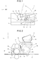
- FIG. 1 is a schematic view showing a configuration of an image forming apparatus employing a developer storing container according to Embodiment 1 of the present invention.
- an image forming apparatus 1 is configured as an electrophotographic printer capable of printing an image of, for example, black (K) on a recording sheet 4 (i.e., a medium).
- the image forming apparatus 1 has a sheet feeding path along which the recording sheet 4 is fed.
- a sheet feeding cassette 3 for storing the recording sheets 4 is mounted to a lower part of the image forming apparatus 1, and defines an upstream end of the sheet feeding path.
- a stacker 28 is formed on a cover 1a of the image forming apparatus 1, and defines a downstream end of the sheet feeding path. Between the sheet feeding cassette 3 and the stacker 28, a pair of registration rollers 8 and 9, a pair of ejection rollers 13 and 14 and another pair of ejection rollers 15 and 16 are disposed along the sheet feeding path.
- a hopping roller 7 is disposed in the vicinity of the sheet feeding cassette 3 for feeding the recording sheet 4 to the sheet feeding path one by one.
- the registration rollers 8 and 9 are disposed on the downstream side of the hopping roller 7 and are configured to correct skew of the recording sheet 4 and feed the recording sheet 4 at a predetermined timing.
- a developing unit 2 and a transfer roller 10 are disposed on the downstream side of the registration rollers 8 and 9.
- the developing unit 2 includes a photosensitive drum 25 on which a toner image is formed.
- the transfer roller 10 is disposed so as to sandwich the recording sheet 4 between the transfer roller 10 and the photosensitive drum 25 to transfer the toner image to the recording sheet 5.
- a fixing unit for fixing the toner image to the recording sheet 5 is disposed on the downstream side of the developing unit 2 and the transfer roller 10, and includes a heat roller 12 and a backup roller 11.
- the ejection rollers 13, 14, 15 and 16 eject the recording sheet 6 (to which the toner image has been fixed) to the stacker 28 outside the image forming apparatus 1.
- the recording sheet has been described with different reference numerals 4, 5 and 6 according to stages of feeding.
- X-direction, Y-direction and Z-direction are defined as follows.
- the X-direction is defined as a feeding direction of the recording sheet 5 when the recording sheet 5 passes the developing unit 2.
- the Y-direction is defined as a direction of a rotational axis of the photosensitive drum 25.
- the Z-direction is defined as being perpendicular to both of the X-direction and Y-direction.
- the X-direction, Y-direction and Z-direction in other figures indicate the same directions as those shown in FIG. 1 .
- the X-direction, Y-direction and Z-direction of the respective figures indicate orientations of respective parts shown in the figures when the parts constitute the image forming apparatus 1 shown in FIG. 1 .
- FIG. 2 is a schematic view showing the developing unit 2 together with the transfer roller 10, an exposing device 17 and a recording sheet 5.
- the developing unit 2 includes the photosensitive drum 25 that bears an electric charge on a circumferential surface thereof in such a manner that the electric charge is removed by exposure.
- the photosensitive drum 25 rotates in a direction shown by an arrow in FIG. 2 .
- the photosensitive drum 25 has a structure in which, for example, a semiconductive rubber such as epichlorohydrin rubber is formed around a conductive metal shaft in the form of a roller.
- a charging roller 24 and an exposing device 17 are disposed in this order in the rotational direction of the photosensitive drum 25.
- the charging roller 24 is pressed against the surface of the photosensitive drum 25 at a constant pressure and supplies electric charge to the surface of the photosensitive drum 25.
- the exposing device 17 is disposed on the main body of the image forming apparatus ( FIG. 1 ), and is composed of, for example, an LED head that exposes the charged surface of the photosensitive drum 25 to form a latent image.
- a developing portion 30 and a cleaning roller 26 are disposed on the downstream side of the exposing device 17 along the rotational direction of the photosensitive drum 25, a developing portion 30 and a cleaning roller 26 are disposed.
- the developing portion 30 causes a toner (i.e., a developer) 27 of a predetermined color (in this example, black) to the surface of the photosensitive drum 25 (on which the latent image is formed) to thereby form a toner image.
- the cleaning roller 26 removes a residual toner that remains on the surface of the photosensitive drum 25 after the toner image is transferred to the recording sheet 5 by the transfer roller 10.
- the developing portion 30 includes a developer storing container 18, a toner holding space 20, a developing roller 22, a toner supplying roller 21, and a developer layer regulating member 23.
- the developer storing container 18 has a toner storing space 19 in which a toner 27 as an unused developer is stored.
- a lower ejection opening 44 in the form of an elongated hole is formed on the bottom of the toner storing space 19 through which the toner 27 in the toner storing space 19 is supplied.
- the toner holding space 20 stores the toner 27 supplied by the developer storing container 18.
- the developing roller 22 is disposed in contact with the photosensitive drum 25.
- the toner supplying roller 21 supplies the toner 27 to the developing roller 22.
- the developer layer regulating member 23 forms a thin layer of the toner 27 having a uniform thickness on the surface of the developing roller 22.
- the developing portion 30 develops the latent image on the photosensitive drum 25 by causing the toner 27 to adhere to the latent image.
- an inner case 50 (see FIG. 4 ) for opening and closing the lower ejection opening 44 is omitted in FIG. 2 for convenience of illustration.
- the developing roller 22, the toner supplying roller 21 and the developer layer regulating member 23 are electrically connected to a developing roller power source (not shown), a supplying roller power source (not shown) and a developer layer regulating member power source (not shown) and are applied with respective bias voltages.
- the developing roller 22 has a structure in which, for example, a semiconductive rubber of silicone or the like is formed around a conductive metal shaft in the form of a roller.
- the toner supplying roller 21 has a structure in which, for example, a rubber (to which a foaming agent has been added in a kneading process for enhancing conveying performance) is formed around a conductive metal shaft in the form of a roller.
- the developing unit 2 is so configured that the developer storing container 18 is detachably disposed above the toner holding space 20 as described later.
- a part of the developing unit 2 except the detachable developer storing container 18 is referred to as a developing unit main body 2a.
- the developing unit main body 2a has a toner replenishing opening (not shown) disposed on a position facing the lower ejection opening 44 of the developer storing container 18, for receiving the toner 27 supplied by the developer storing container 18.
- the transfer roller 10 is disposed facing the photosensitive drum 25 of the developing unit 2.
- the transfer roller 10 is composed of a conductive rubber or the like.
- the transfer roller 10 and the photosensitive drum 25 sandwich a not shown transfer belt that electrostatically absorbs and feeds the recording sheet 5.
- the transfer roller 10 transfers the toner image formed on the photosensitive drum 25 to the recording sheet 5.
- the transfer roller 10 is applied with an electric potential so that a predetermined potential difference is formed between the surface potential of the photosensitive drum 25 and the surface potential of the transfer roller 10.
- the fixing unit ( FIG. 1 ) includes the heat roller 12 and the backup roller 11 and fixes the toner 27 (having been transferred to the recording sheet 5 as shown in FIG. 2 ) to the recording sheet 5 by pressing and heating the toner 27.
- a cover 28 is disposed.on an upper surface of the image forming apparatus 1.
- the cover 28 is swingable so as to be opened and closed. When the cover 28 is opened, the developer storing container 18 can be detached from and mounted to the developing unit main body 2a in the image forming apparatus 1.
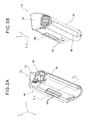
- FIGS. 3A and 3B are bottom perspective views of the toner storing container 18 as seen in opposite directions to each other so as to show the lower ejection opening 44.
- FIG. 4A is a sectional view of the toner storing container 18 taken along line IV-IV in FIG. 3A in a state where the lower ejection opening 44 is closed.
- FIG. 4B is a sectional view of the toner storing container 18 taken along line IV-IV in FIG. 3A in a state where the lower ejection opening 44 is opened.
- FIG. 5 is an exploded perspective view showing the developer storing container 18 as seen in the same direction as the FIG. 3A .
- the developer storing container 18 has an outer case 40, an inner case 50, a side case 60 and an agitation member 70. These components of the developer storing container 18 will be herein described.
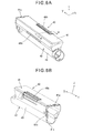
- FIGS. 6A and 6B are top perspective views of an outer case 40 as seen in opposite directions to each other.
- FIG. 7 is a sectional view taken along line VII-VII in FIG. 6A .
- the outer case 40 includes a polygonal portion 41 (i.e., a first hollow portion, a first developer storing portion) and an arc-shaped portion 42 (i.e., a second hollow portion, a second developer storing portion).
- a polygonal portion 41 i.e., a first hollow portion, a first developer storing portion
- an arc-shaped portion 42 i.e., a second hollow portion, a second developer storing portion.
- the arc-shaped portion 42 has a surrounding wall 43 having a cross-section of a circular arc whose center axis C is defined in the Y-direction and whose center angle ⁇ 1 is larger than 180 degrees (in this example, 248 degrees).
- the surrounding wall 43 has both ends 42a and 42b respectively connected to connecting portions 40a and 40b (i.e., first and second outer walls) of the polygonal portion 41.
- the connecting portions 40a and 40b are in the form of flat plates.
- a wall 40c i.e., a third outer wall is formed between the connecting portions 40a and 40b.
- the connecting portions 40a and 40b and the wall 40c form a surrounding wall 41a (i.e., a second surrounding wall) of the polygonal portion 41.
- the connecting portions 40a and 40b extend from the ends 42a and 42b of the surrounding wall 43 in a widening manner.
- connection opening 46 defined by the ends 42a and 42b of the arc-shaped portion 42 (connected to the polygonal portion 41) is elongated in the longitudinal direction of the arc-shaped cross-section portion 42 and has a width defined by the center angle ⁇ 1.
- center angle ⁇ is defined as an angle between a line connecting the end 42a of the surrounding wall 43 and the center axis C and another line connecting the end 42b of the surrounding wall 43 and the center axis C in cross-section (i.e., XZ-section).
- the lower ejecting opening 44 is formed on the surrounding wall 43 of the arc-shaped portion 42 for ejecting the toner.
- the polygonal portion 41 has grip portions 48a and 48b that face each other on both sides of the polygonal portion 41 in the X-direction (i.e., the widthwise direction). These grip portions 48a and 48b have ribs or recesses extending in the longitudinal direction (i.e., the Y-direction) so that a user can easily grip the developer storing container 18.
- FIG. 8 is a top exploded perspective view showing an inner case 50.
- FIG. 9 is a perspective view showing a shutter portion 51 as seen in a direction different from FIG. 8 .
- FIG. 10 is a perspective view showing a lever main body of a lever portion of the inner case 50 as seen in an opposite direction to FIG. 8 so that the inside of the lever main body can be seen.
- XYZ coordinate indicates respective directions in a state where the inner case 50 is in a position to close the lower ejection opening 44 of the developer storing container 18.
- the inner case 50 includes a shutter portion 51 and a lever portion 52 coupled to an end of the shutter portion 51 in the longitudinal direction as described later.
- the shutter portion 51 rotates together with the lever portion 52.
- the inner case 50 is mounted to the outer case 40, the shutter portion 51 is disposed in the outer case 40, and the lever portion 52 protrudes from the outer case 40, as shown in FIG. 3A .
- the shutter portion 51 has a substantially cylindrical shape as shown in FIG. 8 .
- the shutter portion 51 has an upper opening 54 through which the toner in the polygonal portion 41 is supplied via the upper opening 54 to the lower ejection opening 44 in a state where the developer storing container 18 is mounted to the developing unit main body 2a as shown in FIG. 2 . Further, when the inner case 50 is in a position to open the lower ejection opening 44 of the developer storing container 18 as shown in FIG. 4B , the upper opening 54 faces the connection opening 46.
- the upper opening 54 has a size so as not to narrow the connection opening 46.
- At lease one shape-maintaining rib 55 is provided in the upper opening 54, which maintains a cylindrical shape of the shutter portion 51 around the upper opening 54.
- Engaging ribs 56a and 56b are formed on an end of the shutter portion 51 in the longitudinal direction, which engage engaging holes 57a and 57b ( FIG. 10 ) formed on the lever main body 52a.
- the engaging ribs 56a and 56b of the shutter portion 51 have widths different from each other.
- the engaging holes 57a and 57b of the lever main body 52a have widths corresponding to the widths of the engaging ribs 56a and 56b.
- a side wall 58 is formed on an end of the shutter portion 51 in the longitudinal direction on the same side as the engaging ribs 56a and 56b.
- the side wall 58 has an agitation member insertion shaft receiving hole 58a for receiving an agitation member insertion shaft 77 ( FIG. 12 ) of the agitation driving member 71 as described later.
- a seal member 62 composed of urethane sponge or the like is disposed on a predetermined position on the outer circumferential surface of the inner case 50.
- the seal member 62 faces the lower ejection opening 44 of the outer case 50, and contacts the inner surface of the outer case 50 so as to close the lower ejection opening 44.
- the seal member 62 seals the outer case 50 and prevents the toner from leaking through the lower ejection opening 44.
- the seal member 62 is disposed on an area sufficient for entirely sealing the lower ejection opening 44.
- a supplying opening 53 formed on the inner case 50 overlaps with the lower ejection opening 44 of the outer case 40, and opens the lower ejection opening 44.
- the upper opening 54 of the shutter portion 51 faces the connection opening 46 of the outer case 40, and therefore the toner in the polygonal portion 41 is smoothly led to the lower ejection opening 44.
- the lever main body 52a of the lever portion 52 has a substantially cylindrical shape, and includes a knob 59 protruding from the cylindrical part.
- the knob 59 is operated by a user to rotate the lever main body 52a.
- the lever main body 52a has an engaging groove 65 that engages a not shown engaging rib of the developing unit main body 2a when the developer storing container 18 is set in the developing unit main body 2a ( FIG. 2 ).
- the lever main body 52a further includes an agitation driving member mounting portion 66 for mounting the agitation driving member 71, and an agitation force transmitting member mounting portion 67 for mounting an agitation force transmitting member 72.
- the knob 59 has ribs or recesses extending in the axial direction of the lever main body 52a.
- the agitation driving member mounting portion 66 has a post 68 for allowing the agitation driving member 71 to rotate.
- the post 68, the agitation driving member receiving hole 58a and the agitation driving member 71 are aligned with each other in a state where the shutter portion 51 and the lever main body 52a are coupled to each other.
- FIG. 11 is a perspective view showing the agitation force transmitting member mounting portion 67 of the lever main body 52a and the agitation force transmitting member 72 mounted therein.
- the agitation force transmitting member 72 includes shafts 69a and 69b, a driving force receiving portion 74 that receives a force from the developing unit main body 2a and a transmitting portion 73 for transmitting the force to the agitation driving member 71.
- the shafts 69a and 69b, the driving force receiving portion 74 and the transmitting portion 73 are aligned with each other.
- the shafts 69a and 69b are inserted into shaft receiving holes formed on the agitation force transmitting member mounting portion 67 of the lever main body 52a so that the agitation force transmitting member 72 is rotatable.
- the lever 52 is operated to rotate the inner case 50 from a rotational position (as shown in FIG. 4A ) to close the lower ejection opening 44 of the developer storing container 18 to a rotational position (as shown in FIG. 4B ) to open the lower ejection opening 44 of the developer storing container 18.
- the driving force receiving portion 74 engages a not shown transmitting portion of the developer unit main body 2a, and receives a rotational force from the developing unit main body 2a.
- FIGS. 12A and 12B are perspective views showing the agitation driving member 71 as seen in opposite directions to each other.
- the agitation driving member 71 has the agitation member insertion shaft 77 that engages the agitation member 70 ( FIG. 5 ) and a shaft receiving portion 75 that receives the post 68 ( FIG. 10 ).
- the agitation member insertion shaft 77 is disposed on an end of the agitation driving member 71 and the shaft receiving portion 75 is disposed on the other end of the agitation driving member 71.
- an agitation force receiving portion 76 is formed on the outer circumference of the agitation driving member 71, which engages the agitation force transmitting member 72 to receive a driving force.
- the agitation member insertion shaft 77 is inserted into the agitation member insertion shaft receiving hole 58a ( FIG.
- An agitation member insertion groove 78 is formed on the agitation member insertion shaft 77. An end of the crank-shaped agitation member 70 engages the agitation member insertion groove 78, so that the agitation member 70 is able to rotate according to the rotation of the agitation driving member 71.
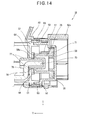
- FIG. 14 is a partially sectional view showing positional relationship between the lever main body 52a, the agitation driving member 71, the agitation force transmitting member 72 and seal members 63 and 64.
- the agitation member insertion shaft 77 of the agitation driving member 71 is inserted into the agitation member insertion shaft receiving hole 58a of the shutter portion 51.
- the seal member 64 is disposed between the shutter portion 51 (to be more specific, the side wall 58) and the agitation driving member 71. The seal member 64 prevents leakage of the toner through between the agitation member insertion shaft receiving hole 58a and the outer surface of the agitation member insertion shaft 77.
- the lever main body 52a (to which the agitation force transmission member 72 is mounted) is coupled to the shutter portion 51 at a rotational position where the engaging ribs 56a and 56b of the lever main body 52a respectively engage the engaging holes 57a and 57b ( FIG. 10 ) in a state where the post 68 engages the shaft receiving portion 75 of the agitation driving member 71.
- the agitation driving member 71 is rotatably supported by the shutter portion 51 and the lever main body 52a. Further, the agitation driving member 71 receives the rotational driving force from the developing unit main body 2a due to the engagement between the agitating force receiving portion 76 and the transmitting portion 73 of the agitation force transmitting member 72 ( FIG.
- the seal member 63 is disposed between the outer case 40, the shutter portion 51 and the lever main body 52a.
- the seal member 63 prevents the leakage through between the shutter portion 51 and the lever main body 52a and through between the lever main body 52a and the inner surface of the outer case 40.
- FIGS. 15A and 15B are perspective views showing shape of a side case 60 as seen in opposite directions to each other.
- latch holes 80a, 80b, 80c and 80d are formed on an outer frame of the side case 60.
- An agitation member shaft receiving portion 79 is formed on an inner side of the side case 60 facing the outer case 40.
- the agitation member shaft receiving portion 79 rotatably supports the end of the crank-shaped agitating member 70 (i.e., opposite to the end supported by the agitation driving member 71).
- the agitation member shaft receiving portion 79 is disposed coaxially with the rotation shaft of the agitation member 71, and the end of the agitation member 70 engages the agitation member shaft receiving portion 79 in such a manner that the latch holes 80a, 80b, 80c and 80d engage latch ribs 81a, 81b, 81c and 81d of the outer case 40.
- the latch ribs 81a, 81b, 81c and 81d are formed on an end portion of the outer case 40 in the longitudinal direction opposite to the end portion to which the lever portion 52 is mounted.
- a seal member 61 ( FIG. 5 ) is disposed between the outer case 40 and the side case 60 for preventing leakage of the toner through between the outer case 40 and the side case 60.
- the seal member 61 is preliminarily mounted to the side case 60 as shown in FIG. 5 .
- the inner case 50 and the side case 60 are mounted to the outer case 40 as shown in FIG. 5 . Both ends of the agitation member 70 are held by the agitation driving member 71 of the lever portion 52 and the agitation member shaft receiving portion 79 of the side case 60.
- the agitation member 70 receives the rotational driving force from the developing unit main body 2a to rotate.
- the inner case 50 is rotated by the operation by the user so as to open and close the lower ejection opening 44.
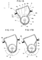
- FIG. 16 is a schematic view for illustrating deformation of the developer storing container 18 when a user strongly grips the developer storing container 18 during the setting of the developer storing container 18 into the developer storing unit main body 2a ( FIG. 2 ).
- the inner surfaces 83a and 83b are inclined with respect to the horizontal surface at inclination angles ⁇ 3 and ⁇ 4 each of which is greater than equal to 50 degrees, so that the toner freely falls down without being stuck on the inner surfaces 83a and 83b in a state where the developer storing container 18 is mounted to the developing unit main body 2a.
- the outer case 40 is so configured that the center angle ⁇ 1 of the arc-shaped portion 42 is greater than or equal to 180 degrees.
- the edge portions 46a and 46b of the connection opening 46 press an upper half part of the shutter portion 51 (of substantially cylindrical shape) from both sides substantially in horizontal direction, and a force that presses the shutter portion 51 downward is generated.
- the seal member 62 disposed on the shutter portion 51 is strongly pressed against the lower ejection opening 44 of the outer case 40, and therefore sealing of the lower ejection opening 44 is enhanced.
- FIGS. 17A and 17B show configurations of developer storing containers according to comparative examples with respect to Embodiment 1.
- the outer case 40 is so configured that the center angle ⁇ 1 of the arc-shaped portion 42 is less than 180 degrees.
- the outer case 40 is so configured that the center angle ⁇ 1 of the arc-shaped portion 42 is greater than 180 degrees, but the outer case 40 has another exterior wall 401 that makes the arc-shaped portion of the outer case 40 have a center angle ⁇ 1 less than or equal to 180 degrees.
- the lower ejection opening 44 is widened as the grip portions 48a and 48b deform inwardly. Therefore, a gap may be formed between the lower ejection opening 44 and the seal member 62 and the toner may leak outside therethrough. In such cases, it is necessary to strongly push the seal member 62 against the inner surface of the ejection opening 44 for preventing the leakage of the toner, which increases a load for rotating the inner case 50 (i.e., a load for operating the knob 59).
- the outer case is explained as an integrally-formed member in this embodiment, it is also possible that the arc-shaped portion and the polygonal portion are formed as separate members and coupled to each other. Further, although the shutter portion and the lever portion of the inner case are formed as separate members in this embodiment, it is also possible that the shutter portion and the lever portion of the inner case are integrally formed.
- the side case is mounted to the outer case by means of the latches in this embodiment, it is also possible that the side case can be fixed to the outer case by means of welding or bonding. In this case, it is not necessary to provide a seal member between the side case and the outer case.
- the agitation member is provided in this embodiment, it is also possible not to use the agitation member. In this case, members or structures for driving the agitation member can be eliminated.
- the polygonal portion 41 may be applied with an external force, for example, when the outer case 40 of the polygonal portion 41 is strongly gripped or hit.
- the seal member 62 disposed on the shutter portion 51 of the inner case 50
- the lower ejection opening 44 of the outer case 40 is strongly pressed against the lower ejection opening 44 of the outer case 40. Therefore, sealing of the lower ejection portion 44 (particularly, when the developer storing container 18 is held outside the image forming apparatus 1) is enhanced, and it becomes possible to prevent the toner from leaking outside.
- FIG. 18 is a bottom view of a developer storing container 118 for illustrating a lower ejection opening thereof according to Embodiment 2 of the present invention.
- an outer case 140 of the developer storing container 118 of Embodiment 2 includes an arc-shaped portion 142 having two lower ejection openings 144a and 144b formed on the bottom of the arc-shaped portion 142.
- Other parts of the developer storing container 118 are the same as those of the developer storing container 18 of Embodiment 1.
- Components of the image forming apparatus according to Embodiment 2 which are the same as those of the image forming apparatus 1 ( FIG. 1 ) according to Embodiment 1 are assigned the same reference numerals or omitted in figures. Descriptions will be focused on differences between the Embodiments 1 and 2.
- the lower ejection openings 144a and 144b are so configured that a connection rib 150 is added to a center portion of the lower ejection opening 44 ( FIG. 5 ) of the outer case 40 of Embodiment 1.
- the connection rib 150 divides the lower ejection openings 144a and 144b so that lower ejection openings 144a and 144b are adjacent to each other.
- Each of the lower ejection openings 144a and 144b has a length in the longitudinal direction which is less than or equal to 1/2 of an entire length of the developer storing container 118 in the longitudinal direction.
- the lower ejection openings 144a and 144b are strongly pressed from the inside by the seal member 62 disposed on the inner case 50. In this state, the lengths of the lower ejection openings 144a and 144b are short because of the connection rib 150, and therefore outward deformations of the lower ejection openings 144a and 144b are restricted.
- the developer storing container 18 according to Embodiment 1 has the lower ejection opening 44 having a longer length, and therefore the lower ejection opening 44 relatively easily deform outwardly compared with the lower ejection openings 144a and 144b according to Embodiment 2.
- FIGS. 19 through 21 show modifications of the developer storing container according to Embodiment 2.
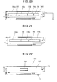
- the developer storing container of a modification shown in FIG. 19 has a configuration in which two connection ribs 150 are added to the lower ejection opening 44 ( FIG. 5 ) of the outer case 40 of Embodiment 1.
- the connection ribs 150 divide the lower ejection opening into three lower ejection openings 144a, 144b and 144c.
- Each of the lower ejection openings 144a, 144b and 144c has a length in the longitudinal direction which is less than or equal to 1/2 of an entire length of the developer storing container 118 in the longitudinal direction.
- the developer storing container of a modification shown in FIG. 20 has a configuration in which three connection ribs 150 are added to the lower ejection opening 44 ( FIG. 5 ) of the outer case 40 of Embodiment 1.
- the connection ribs 150 unevenly divide the lower ejection opening into four lower ejection openings 144a, 144b, 144c and 144d.
- Each of the lower ejection openings 144a, 144b, 144c and 144d has a length in the longitudinal direction which is less than or equal to 1/2 of an entire length of the developer storing container 118 in the longitudinal direction.
- the developer storing container of a modification shown in FIG. 21 has a configuration in which two inclined connection ribs 150 are added to the lower ejection opening 44 ( FIG. 5 ) of the outer case 40 of Embodiment 1.
- the connection ribs 150 obliquely divide the lower ejection opening into three lower ejection openings 144a, 144b and 144c.
- Each of the lower ejection openings 144a, 144b and 144c has a length in the longitudinal direction which is less than or equal to 1/2 of an entire length of the developer storing container 118 in the longitudinal direction.
- the number of the lower ejection openings can be varied ( FIG. 19 ), the lower ejection openings can have uneven lengths ( FIG. 20 ), and the lower ejection openings can have oblique shapes ( FIG. 21 ).
- the provision of the rib 150 contributes to enhancement in rigidity of the lower ejection openings 144a and 144b. Therefore, even when the lower ejection openings 144a and 144b are strongly pressed from the inside by the seal member 62, outward deformations of the lower ejection openings 144a and 144b are restricted. Therefore, decrease in sealing properties of the developer storing container 118 can be prevented.
- FIG. 22 is a bottom view showing a developer storing container for illustrating an ejection opening according to Embodiment 3 of the present invention.
- the image forming apparatus using the developer storing container 218 according to Embodiment 3 is different from the image forming apparatus 1 according to Embodiment 1 in the following aspects.
- the lower ejection opening 244 formed on the bottom of an arc-shaped portion 242 of an outer case 240 has a length in the longitudinal direction which is less than or equal to 1/2 of the entire length of the developer storing container 218 in the longitudinal direction.
- a supplying opening (not shown) formed on the inner case 50 (see FIG. 9 ) of Embodiment 3 has a size which is substantially the same as the lower ejection opening 244, which is smaller than the supplying opening 53 ( FIG. 9 ) of the inner case 50 of Embodiment 1.
- a seal member (not shown) disposed on the inner case 50 of Embodiment 3 has a size sufficient for sealing the lower ejection opening 244, which is smaller than the seal member 62 ( FIG. 8 ) of Embodiment 1.
- Other parts of the developer storing container 218 are the same as those of the developer storing container 18 of Embodiment 1.
- Components of the image forming apparatus according to Embodiment 3 which are the same as those of the image forming apparatus 1 ( FIG. 1 ) according to Embodiment 1 are assigned the same reference numerals or omitted in figures. Descriptions will be focused on differences between the Embodiments 1 and 3.
- the lower ejection opening 244 is strongly pressed from the inside by the seal member (not shown) disposed on the inner case 50.
- the lower ejection opening 244 has the length (in the longitudinal direction) which is less than or equal to 1/2 of the entire length of the developer storing container 218 in the longitudinal direction, and therefore outward deformation of the lower ejection opening 244 is restricted.
- the developer storing container 18 according to Embodiment 1 has the lower ejection opening 44 having a longer length, and therefore the lower ejection opening 44 relatively easily deform outwardly when pressed by the seal member 62 from the inside, compared with the lower ejection opening 244 according to Embodiment 3.
- the lower ejection opening 244 has the length (in the longitudinal direction) which is less than or equal to 1/2 of the entire length of the developer storing container 218 in the longitudinal direction, and therefore the rigidity of the lower ejection opening 244 is enhanced. Therefore, even when the lower ejection opening 244 is strongly pressed from the inside by the seal member 62, outward deformation of the lower ejection opening 244 is restricted. Therefore, decrease in sealing properties of the developer storing container 218 can be prevented. Moreover, the length of the seal member (in the longitudinal direction) disposed on the inner case can be reduced, and a rotational load of the inner case can be reduced. Therefore, a developer storing container which is easy to operate can be obtained.
- the outer case 40 includes the arc-shaped portion 42 and the polygonal portion 41 as shown in FIG. 7 .
- the present invention is not limited to such a configuration.
- a polygonal portion 301 has a substantially triangular cross-section and an arc-shaped portion 302 has a substantially polygonal cross-section as shown in FIG. 23A .
- a constricted portion 300 is formed between the polygonal portion 301 and the arc-shaped portion 302.
- a polygonal portion 303 has a substantially arc-shaped cross-section and an arc-shaped portion 304 has an elongated circular cross-section as shown in FIG. 23B .
- a constricted portion 305 is formed between the polygonal portion 303 and the arc-shaped portion 304. Further, various types modifications are employable.
Landscapes
- Physics & Mathematics (AREA)
- General Physics & Mathematics (AREA)
- Dry Development In Electrophotography (AREA)
Applications Claiming Priority (1)
| Application Number | Priority Date | Filing Date | Title |
|---|---|---|---|
| JP2008013556A JP4598089B2 (ja) | 2008-01-24 | 2008-01-24 | 現像剤収容器及び画像形成装置 |
Publications (3)
| Publication Number | Publication Date |
|---|---|
| EP2085829A2 true EP2085829A2 (de) | 2009-08-05 |
| EP2085829A3 EP2085829A3 (de) | 2009-08-12 |
| EP2085829B1 EP2085829B1 (de) | 2011-03-23 |
Family
ID=40775499
Family Applications (1)
| Application Number | Title | Priority Date | Filing Date |
|---|---|---|---|
| EP09150900A Ceased EP2085829B1 (de) | 2008-01-24 | 2009-01-20 | Entwickleraufbewahrungsbehälter und Bilderzeugungsvorrichtung |
Country Status (5)
| Country | Link |
|---|---|
| US (1) | US8200127B2 (de) |
| EP (1) | EP2085829B1 (de) |
| JP (1) | JP4598089B2 (de) |
| CN (1) | CN101493666B (de) |
| DE (1) | DE602009000924D1 (de) |
Families Citing this family (15)
| Publication number | Priority date | Publication date | Assignee | Title |
|---|---|---|---|---|
| JP4689422B2 (ja) * | 2005-09-27 | 2011-05-25 | 株式会社沖データ | 現像剤カートリッジ、画像形成ユニット及び画像形成装置 |
| JP5141717B2 (ja) | 2010-05-17 | 2013-02-13 | ブラザー工業株式会社 | 画像形成装置 |
| JP4998588B2 (ja) | 2010-05-17 | 2012-08-15 | ブラザー工業株式会社 | トナーボックスおよび現像装置 |
| JP4947188B2 (ja) | 2010-05-17 | 2012-06-06 | ブラザー工業株式会社 | トナーボックスおよび現像装置 |
| JP4947187B2 (ja) * | 2010-05-17 | 2012-06-06 | ブラザー工業株式会社 | トナーボックスおよび現像装置 |
| JP5012951B2 (ja) | 2010-05-17 | 2012-08-29 | ブラザー工業株式会社 | トナーボックス |
| JP5444116B2 (ja) * | 2010-05-17 | 2014-03-19 | 株式会社沖データ | 現像剤収容体、画像形成ユニット及び画像形成装置 |
| JP5659717B2 (ja) * | 2010-11-10 | 2015-01-28 | 富士ゼロックス株式会社 | 現像剤の収容容器および画像形成装置 |
| JP5212505B2 (ja) | 2011-02-28 | 2013-06-19 | ブラザー工業株式会社 | 画像形成装置 |
| JP5656740B2 (ja) * | 2011-05-23 | 2015-01-21 | 株式会社沖データ | 現像剤収容体、画像形成ユニット及び画像形成装置 |
| JP5690655B2 (ja) | 2011-05-26 | 2015-03-25 | 株式会社沖データ | 画像形成ユニット |
| CN202631957U (zh) * | 2012-05-18 | 2012-12-26 | 珠海天威飞马打印耗材有限公司 | 碳粉盒 |
| JP5896358B2 (ja) * | 2013-01-21 | 2016-03-30 | 株式会社沖データ | 現像剤収容器、現像装置及び画像形成装置 |
| JP5785969B2 (ja) * | 2013-02-27 | 2015-09-30 | 株式会社沖データ | 現像剤収容器、現像装置、及び画像形成装置 |
| JP6366423B2 (ja) * | 2014-08-20 | 2018-08-01 | キヤノン株式会社 | 現像剤容器、プロセスカートリッジ及び画像形成装置 |
Citations (1)
| Publication number | Priority date | Publication date | Assignee | Title |
|---|---|---|---|---|
| JP2001042620A (ja) | 1999-07-30 | 2001-02-16 | Oki Data Corp | トナーカートリッジおよびその製造方法 |
Family Cites Families (11)
| Publication number | Priority date | Publication date | Assignee | Title |
|---|---|---|---|---|
| JPS60130772A (ja) * | 1983-12-20 | 1985-07-12 | Fuji Xerox Co Ltd | トナ−補給容器 |
| JP3408166B2 (ja) * | 1997-09-30 | 2003-05-19 | キヤノン株式会社 | トナー供給容器及び電子写真画像形成装置 |
| JP3461330B2 (ja) * | 2000-08-25 | 2003-10-27 | キヤノン株式会社 | 電子写真画像形成システム、電子写真画像形成装置、プロセスカートリッジ、及び、メモリー部材 |
| JP3893259B2 (ja) * | 2001-08-07 | 2007-03-14 | 株式会社沖データ | トナーカートリッジと画像形成装置 |
| JP4629508B2 (ja) | 2005-06-09 | 2011-02-09 | 株式会社沖データ | トナーカートリッジ及びその着脱機構 |
| KR100677595B1 (ko) * | 2005-06-10 | 2007-02-02 | 삼성전자주식회사 | 현상기 및 이를 채용한 칼라화상형성장치 |
| EP1767999B1 (de) * | 2005-09-21 | 2012-03-21 | Brother Kogyo Kabushiki Kaisha | Tonerkassette für Entwicklungseinheit |
| EP1927897B1 (de) * | 2006-09-22 | 2010-11-03 | Brother Kogyo Kabushiki Kaisha | Bilderzeugungsvorrichtung und Entwicklungsmittelkartusche |
| EP1939695B1 (de) * | 2006-12-28 | 2015-07-29 | Brother Kogyo Kabushiki Kaisha | Bilderzeugungsvorrichtung mit der Fähigkeit zur präzisen Positionierung der Entwicklungseinheit und der Entwicklerkartusche |
| JP5039390B2 (ja) * | 2007-02-02 | 2012-10-03 | 株式会社リコー | プロセスカートリッジ及び画像形成装置 |
| JP4612073B2 (ja) * | 2008-03-19 | 2011-01-12 | 株式会社沖データ | 粉体収容器、現像装置及び画像形成装置 |
-
2008
- 2008-01-24 JP JP2008013556A patent/JP4598089B2/ja not_active Expired - Fee Related
-
2009
- 2009-01-20 DE DE602009000924T patent/DE602009000924D1/de active Active
- 2009-01-20 EP EP09150900A patent/EP2085829B1/de not_active Ceased
- 2009-01-23 CN CN2009100028595A patent/CN101493666B/zh not_active Expired - Fee Related
- 2009-01-23 US US12/320,319 patent/US8200127B2/en not_active Expired - Fee Related
Patent Citations (1)
| Publication number | Priority date | Publication date | Assignee | Title |
|---|---|---|---|---|
| JP2001042620A (ja) | 1999-07-30 | 2001-02-16 | Oki Data Corp | トナーカートリッジおよびその製造方法 |
Also Published As
| Publication number | Publication date |
|---|---|
| EP2085829A3 (de) | 2009-08-12 |
| US20090190963A1 (en) | 2009-07-30 |
| JP4598089B2 (ja) | 2010-12-15 |
| CN101493666B (zh) | 2013-03-13 |
| DE602009000924D1 (de) | 2011-05-05 |
| US8200127B2 (en) | 2012-06-12 |
| JP2009175403A (ja) | 2009-08-06 |
| CN101493666A (zh) | 2009-07-29 |
| EP2085829B1 (de) | 2011-03-23 |
Similar Documents
| Publication | Publication Date | Title |
|---|---|---|
| EP2085829B1 (de) | Entwickleraufbewahrungsbehälter und Bilderzeugungsvorrichtung | |
| CN110320782B (zh) | 鼓单元和包括鼓单元的鼓组件 | |
| US9494893B2 (en) | Developing cartridge and method for manufacturing the same | |
| EP2280315B1 (de) | Prozesskartusche und damit versehenes Bilderzeugungsgerät | |
| EP2110713B1 (de) | Puderentwickleraufnahmevorrichtung, Entwicklungsvorrichtung und Bilderzeugungsvorrichtung | |
| CN116243573A (zh) | 显影剂盒 | |
| CN101393417A (zh) | 显影装置和具有该装置的成象设备 | |
| EP2378375B1 (de) | Entwicklerspeicherkörper, Entwicklervorrichtung und Bilderzeugungsvorrichtung | |
| JP6615402B2 (ja) | カートリッジおよび画像形成装置 | |
| US10649400B2 (en) | Image forming apparatus with features that suppress deformation of door caused by counterforce from cartridge | |
| EP2942671B1 (de) | Entwicklungseinheit, bilderzeugungseinheit und bilderzeugungsvorrichtung | |
| JP4861122B2 (ja) | 画像形成装置 | |
| CN223757035U (zh) | 一种显影盒 | |
| US20250328093A1 (en) | Developer storage body, image forming unit, and image forming apparatus | |
| US20070048019A1 (en) | Coupling structure usable with image forming apparatus | |
| JP7635565B2 (ja) | 現像装置、現像装置を備える画像形成装置 | |
| JP2020091326A (ja) | 現像剤容器、現像装置、プロセスカートリッジ及び画像形成装置 | |
| CN110068995B (zh) | 成像装置 | |
| JP4766977B2 (ja) | 粉体収容容器 | |
| JP7242304B2 (ja) | 画像形成装置 | |
| JP2025002115A (ja) | 画像形成装置 |
Legal Events
| Date | Code | Title | Description |
|---|---|---|---|
| PUAI | Public reference made under article 153(3) epc to a published international application that has entered the european phase |
Free format text: ORIGINAL CODE: 0009012 |
|
| PUAL | Search report despatched |
Free format text: ORIGINAL CODE: 0009013 |
|
| AK | Designated contracting states |
Kind code of ref document: A2 Designated state(s): AT BE BG CH CY CZ DE DK EE ES FI FR GB GR HR HU IE IS IT LI LT LU LV MC MK MT NL NO PL PT RO SE SI SK TR |
|
| AX | Request for extension of the european patent |
Extension state: AL BA RS |
|
| AK | Designated contracting states |
Kind code of ref document: A3 Designated state(s): AT BE BG CH CY CZ DE DK EE ES FI FR GB GR HR HU IE IS IT LI LT LU LV MC MK MT NL NO PL PT RO SE SI SK TR |
|
| AX | Request for extension of the european patent |
Extension state: AL BA RS |
|
| 17P | Request for examination filed |
Effective date: 20100212 |
|
| 17Q | First examination report despatched |
Effective date: 20100309 |
|
| AKX | Designation fees paid |
Designated state(s): DE FR GB NL |
|
| GRAP | Despatch of communication of intention to grant a patent |
Free format text: ORIGINAL CODE: EPIDOSNIGR1 |
|
| GRAS | Grant fee paid |
Free format text: ORIGINAL CODE: EPIDOSNIGR3 |
|
| GRAA | (expected) grant |
Free format text: ORIGINAL CODE: 0009210 |
|
| AK | Designated contracting states |
Kind code of ref document: B1 Designated state(s): DE FR GB NL |
|
| REG | Reference to a national code |
Ref country code: GB Ref legal event code: FG4D |
|
| REF | Corresponds to: |
Ref document number: 602009000924 Country of ref document: DE Date of ref document: 20110505 Kind code of ref document: P |
|
| REG | Reference to a national code |
Ref country code: DE Ref legal event code: R096 Ref document number: 602009000924 Country of ref document: DE Effective date: 20110505 |
|
| REG | Reference to a national code |
Ref country code: NL Ref legal event code: T3 |
|
| PLBE | No opposition filed within time limit |
Free format text: ORIGINAL CODE: 0009261 |
|
| STAA | Information on the status of an ep patent application or granted ep patent |
Free format text: STATUS: NO OPPOSITION FILED WITHIN TIME LIMIT |
|
| 26N | No opposition filed |
Effective date: 20111227 |
|
| REG | Reference to a national code |
Ref country code: DE Ref legal event code: R097 Ref document number: 602009000924 Country of ref document: DE Effective date: 20111227 |
|
| REG | Reference to a national code |
Ref country code: FR Ref legal event code: PLFP Year of fee payment: 8 |
|
| REG | Reference to a national code |
Ref country code: FR Ref legal event code: PLFP Year of fee payment: 9 |
|
| REG | Reference to a national code |
Ref country code: FR Ref legal event code: PLFP Year of fee payment: 10 |
|
| REG | Reference to a national code |
Ref country code: DE Ref legal event code: R081 Ref document number: 602009000924 Country of ref document: DE Owner name: OKI ELECTRIC INDUSTRY CO., LTD., JP Free format text: FORMER OWNER: OKI DATA CORP., TOKIO/TOKYO, JP |
|
| REG | Reference to a national code |
Ref country code: GB Ref legal event code: 732E Free format text: REGISTERED BETWEEN 20220317 AND 20220323 |
|
| REG | Reference to a national code |
Ref country code: NL Ref legal event code: PD Owner name: OKI ELECTRIC INDUSTRY CO., LTD.; JP Free format text: DETAILS ASSIGNMENT: CHANGE OF OWNER(S), MERGE; FORMER OWNER NAME: OKI DATA CORPORATION Effective date: 20220308 |
|
| PGFP | Annual fee paid to national office [announced via postgrant information from national office to epo] |
Ref country code: NL Payment date: 20221220 Year of fee payment: 15 Ref country code: GB Payment date: 20221201 Year of fee payment: 15 Ref country code: FR Payment date: 20221208 Year of fee payment: 15 |
|
| PGFP | Annual fee paid to national office [announced via postgrant information from national office to epo] |
Ref country code: DE Payment date: 20221130 Year of fee payment: 15 |
|
| REG | Reference to a national code |
Ref country code: DE Ref legal event code: R119 Ref document number: 602009000924 Country of ref document: DE |
|
| REG | Reference to a national code |
Ref country code: NL Ref legal event code: MM Effective date: 20240201 |
|
| GBPC | Gb: european patent ceased through non-payment of renewal fee |
Effective date: 20240120 |
|
| PG25 | Lapsed in a contracting state [announced via postgrant information from national office to epo] |
Ref country code: DE Free format text: LAPSE BECAUSE OF NON-PAYMENT OF DUE FEES Effective date: 20240801 |
|
| PG25 | Lapsed in a contracting state [announced via postgrant information from national office to epo] |
Ref country code: GB Free format text: LAPSE BECAUSE OF NON-PAYMENT OF DUE FEES Effective date: 20240120 |
|
| PG25 | Lapsed in a contracting state [announced via postgrant information from national office to epo] |
Ref country code: FR Free format text: LAPSE BECAUSE OF NON-PAYMENT OF DUE FEES Effective date: 20240131 |
|
| PG25 | Lapsed in a contracting state [announced via postgrant information from national office to epo] |
Ref country code: NL Free format text: LAPSE BECAUSE OF NON-PAYMENT OF DUE FEES Effective date: 20240201 |
|
| PG25 | Lapsed in a contracting state [announced via postgrant information from national office to epo] |
Ref country code: NL Free format text: LAPSE BECAUSE OF NON-PAYMENT OF DUE FEES Effective date: 20240201 Ref country code: GB Free format text: LAPSE BECAUSE OF NON-PAYMENT OF DUE FEES Effective date: 20240120 Ref country code: FR Free format text: LAPSE BECAUSE OF NON-PAYMENT OF DUE FEES Effective date: 20240131 Ref country code: DE Free format text: LAPSE BECAUSE OF NON-PAYMENT OF DUE FEES Effective date: 20240801 |