EP2085603A1 - Système et procédé pour éviter la surchauffe de pompe CR - Google Patents
Système et procédé pour éviter la surchauffe de pompe CR Download PDFInfo
- Publication number
- EP2085603A1 EP2085603A1 EP08001853A EP08001853A EP2085603A1 EP 2085603 A1 EP2085603 A1 EP 2085603A1 EP 08001853 A EP08001853 A EP 08001853A EP 08001853 A EP08001853 A EP 08001853A EP 2085603 A1 EP2085603 A1 EP 2085603A1
- Authority
- EP
- European Patent Office
- Prior art keywords
- fuel
- pump
- pressure
- pressure fuel
- pump mode
- Prior art date
- Legal status (The legal status is an assumption and is not a legal conclusion. Google has not performed a legal analysis and makes no representation as to the accuracy of the status listed.)
- Withdrawn
Links
Images


Classifications
-
- F—MECHANICAL ENGINEERING; LIGHTING; HEATING; WEAPONS; BLASTING
- F02—COMBUSTION ENGINES; HOT-GAS OR COMBUSTION-PRODUCT ENGINE PLANTS
- F02M—SUPPLYING COMBUSTION ENGINES IN GENERAL WITH COMBUSTIBLE MIXTURES OR CONSTITUENTS THEREOF
- F02M37/00—Apparatus or systems for feeding liquid fuel from storage containers to carburettors or fuel-injection apparatus; Arrangements for purifying liquid fuel specially adapted for, or arranged on, internal-combustion engines
- F02M37/04—Feeding by means of driven pumps
- F02M37/18—Feeding by means of driven pumps characterised by provision of main and auxiliary pumps
-
- F—MECHANICAL ENGINEERING; LIGHTING; HEATING; WEAPONS; BLASTING
- F02—COMBUSTION ENGINES; HOT-GAS OR COMBUSTION-PRODUCT ENGINE PLANTS
- F02D—CONTROLLING COMBUSTION ENGINES
- F02D33/00—Controlling delivery of fuel or combustion-air, not otherwise provided for
- F02D33/003—Controlling the feeding of liquid fuel from storage containers to carburettors or fuel-injection apparatus ; Failure or leakage prevention; Diagnosis or detection of failure; Arrangement of sensors in the fuel system; Electric wiring; Electrostatic discharge
- F02D33/006—Controlling the feeding of liquid fuel from storage containers to carburettors or fuel-injection apparatus ; Failure or leakage prevention; Diagnosis or detection of failure; Arrangement of sensors in the fuel system; Electric wiring; Electrostatic discharge depending on engine operating conditions, e.g. start, stop or ambient conditions
-
- F—MECHANICAL ENGINEERING; LIGHTING; HEATING; WEAPONS; BLASTING
- F02—COMBUSTION ENGINES; HOT-GAS OR COMBUSTION-PRODUCT ENGINE PLANTS
- F02D—CONTROLLING COMBUSTION ENGINES
- F02D41/00—Electrical control of supply of combustible mixture or its constituents
- F02D41/30—Controlling fuel injection
- F02D41/38—Controlling fuel injection of the high pressure type
- F02D41/3809—Common rail control systems
- F02D41/3836—Controlling the fuel pressure
- F02D41/3845—Controlling the fuel pressure by controlling the flow into the common rail, e.g. the amount of fuel pumped
-
- F—MECHANICAL ENGINEERING; LIGHTING; HEATING; WEAPONS; BLASTING
- F02—COMBUSTION ENGINES; HOT-GAS OR COMBUSTION-PRODUCT ENGINE PLANTS
- F02M—SUPPLYING COMBUSTION ENGINES IN GENERAL WITH COMBUSTIBLE MIXTURES OR CONSTITUENTS THEREOF
- F02M59/00—Pumps specially adapted for fuel-injection and not provided for in groups F02M39/00 -F02M57/00, e.g. rotary cylinder-block type of pumps
- F02M59/44—Details, components parts, or accessories not provided for in, or of interest apart from, the apparatus of groups F02M59/02 - F02M59/42; Pumps having transducers, e.g. to measure displacement of pump rack or piston
-
- F—MECHANICAL ENGINEERING; LIGHTING; HEATING; WEAPONS; BLASTING
- F02—COMBUSTION ENGINES; HOT-GAS OR COMBUSTION-PRODUCT ENGINE PLANTS
- F02M—SUPPLYING COMBUSTION ENGINES IN GENERAL WITH COMBUSTIBLE MIXTURES OR CONSTITUENTS THEREOF
- F02M63/00—Other fuel-injection apparatus having pertinent characteristics not provided for in groups F02M39/00 - F02M57/00 or F02M67/00; Details, component parts, or accessories of fuel-injection apparatus, not provided for in, or of interest apart from, the apparatus of groups F02M39/00 - F02M61/00 or F02M67/00; Combination of fuel pump with other devices, e.g. lubricating oil pump
- F02M63/02—Fuel-injection apparatus having several injectors fed by a common pumping element, or having several pumping elements feeding a common injector; Fuel-injection apparatus having provisions for cutting-out pumps, pumping elements, or injectors; Fuel-injection apparatus having provisions for variably interconnecting pumping elements and injectors alternatively
- F02M63/0225—Fuel-injection apparatus having a common rail feeding several injectors ; Means for varying pressure in common rails; Pumps feeding common rails
-
- F—MECHANICAL ENGINEERING; LIGHTING; HEATING; WEAPONS; BLASTING
- F02—COMBUSTION ENGINES; HOT-GAS OR COMBUSTION-PRODUCT ENGINE PLANTS
- F02D—CONTROLLING COMBUSTION ENGINES
- F02D2200/00—Input parameters for engine control
- F02D2200/02—Input parameters for engine control the parameters being related to the engine
- F02D2200/06—Fuel or fuel supply system parameters
- F02D2200/0602—Fuel pressure
Definitions
- the present disclosure refers to a fuel injection system, in particular but not exclusively to a method for controlling two or more high-pressure fuel pumps for pumping fuel having a high pressure into a high-pressure fuel distribution line system.
- Conventional fuel injection systems for internal combustion engines may include one high-pressure fuel pump for supplying a predetermined amount of fuel at a high pressure to injection nozzles within a fuel injection system.
- more than one high-pressure fuel pump may be provided for delivering a sufficient amount of fuel at a high pressure to the engine, in particular a diesel engine, operating at a desired load.
- the high-pressure fuel pumps may be driven directly by the internal combustion engine. In such an arrangement it may not be possible to shut-off the fuel pumps during operation. However, the amount of fuel supplied to the pumping elements of the fuel pumps can be adjusted via flow control valves.
- An engine control module (ECM), or more generally a control unit, may be provided for controlling the flow control valves.
- a high-pressure fuel pump may have a pumping unit or several pumping elements in which fuel leakage can occur. Fuel leakage may occur for example in a piston pump between a piston and a piston guide. The fuel leaked from the pumping element will not be pumped into the high-pressure distribution line system. Typically, the fuel leaking from the pumping element and not being pumped is recycled to an intake section of the high-pressure fuel pump. Due to the recycling of the fuel leaked from the pumping element, heat is generated in accordance with the pressure and the amount of fuel leaked from the pumping element, which heats the fuel and the parts of the high-pressure fuel pump that are contacted by or are near this fuel.
- the heating may not actually cause a problem because, in addition to the heated, leaked fuel, new fuel having a lower temperature is supplied from a fuel tank, such that the mixture of the leaked fuel and the new fuel will have a temperature below a critical limit.
- the situation may become critical if the internal combustion engine is operated at an idling speed or at a low load with a corresponding low fuel consumption for too long of a time period. In this case, the ratio between the leaked fuel and the amount of new fuel supplied is relatively large and, consequently, the temperature of this mixture may rise.
- the temperature of the parts of the high-pressure contacted by this mixture will increase, because the portion of fuel leaked from the pumping element is relatively high in comparison to the portion of the new fuel from the tank having the lower temperature. Consequently, parts of the high-pressure fuel pump may heat up to a temperature at which damage can occur.
- a fuel injection system for an internal combustion engine comprises one fuel pump. It is stated that the heating of fuel in such a fuel injection system might be a problem.
- the fuel pump is driven by the internal combustion engine.
- a control unit is connected with the coupling such that, upon actuating, the coupling pressure generated by the fuel pump can be adjusted to the injection pressure.
- the disclosed arrangement eliminates an undesired heating of the fuel in the section of the pressure piping leading to the injection valves, because the energy supplied by the internal combustion engine for the fuel pump is only used as necessary for generating the necessary injection pressure. The remaining energy is dissipated into the coupling.
- This known arrangement requires a coupling and a control unit for such a coupling.
- EP 1 167 731 A2 a method for monitoring the operation of the pump function for vehicles having at least two electrical fuel pumps is disclosed. It is mentioned therein that, in case one of the fuel pumps fails, the other fuel pump may pump an amount of fuel up to a maximum. However, if the internal combustion engine should be operated at full load, a pressure drop may occur at the working fuel pump. Consequently, a temperature increase may occur, which in turn might damage parts, e.g. the catalytic converter or the exhaust manifold. For this reason, a method for monitoring the operation of the pumps is proposed in which the fuel pumps are alternatively operated. The output rate of each fuel pump is determined and compared with set-points.
- the present disclosure is directed to overcoming or alleviating one or more of the problems set forth above.
- a fuel injection system for supplying fuel at a high-pressure to an internal combustion engine comprises at least one first high-pressure fuel pump and at least one second high-pressure fuel pump, both first and second high-pressure fuel pumps being configured to pump fuel at a high pressure into a high-pressure fuel distribution line system connected with the internal combustion engine.
- Each of the high-pressure fuel pumps is configured to be operated in a first pump mode and a second pump mode. In the first pump mode, a first amount of fuel is pumped, said first amount of fuel being associated with a first engine output. In the second pump mode, a second amount of fuel is pumped, said second amount of fuel being associated with a second engine output which is greater than the first output.
- a control unit is configured to alternately operate the at least two high-pressure fuel pumps such that during a first time period at least the first high-pressure fuel pump is operated in the first pump mode and at least the second high-pressure fuel pump is simultaneously operated in the second pump mode, and such that, during a second time period at least the second high-pressure fuel pump is operated in the first pump mode and at least the first high-pressure fuel pump is simultaneously operated in the second pump mode.
- a method for controlling at least a first fuel pump and a second fuel pump, both said first and second fuel pumps being configured to supply fuel to an internal combustion engine may comprise operating for a first time period at least said first pump in a first pump mode and simultaneously operating at least one said second fuel pump in a second pump mode, and operating for a second time period at least said first fuel pump in the second pump mode and simultaneously operating at least one said second fuel pump in the first pump mode.
- a control unit for a fuel injection system for supplying fuel at a high-pressure to an internal combustion engine may comprise at least two high-pressure fuel pumps for pumping fuel at a high pressure into a high-pressure fuel distribution line system connected with the internal combustion engine.
- Each high-pressure fuel pump may include a fuel intake section, a high-pressure pumping element disposed downstream of the fuel intake section, and a return line provided for recycling fuel leaked from the pumping element to the associated fuel intake section.
- Each of the high-pressure fuel pumps may be operated in a first pump mode and a second pump mode, the first pump mode being specified in that a first amount of fuel is being pumped, and the second pump mode being specified in that a second amount of fuel for operating the internal combustion engine is being pumped.
- the control unit may be configured to alternately operate for a first period at least one of the high-pressure fuel pumps in the first pump mode, and simultaneously to operate at least one other high-pressure fuel pump in the second pump mode, and for a second period at least one of the high-pressure fuel pumps operated in the first period in the second pump mode in the first pump mode and simultaneously operate at least one other high-pressure fuel pump in the second pump mode.
- a computer program comprises executable instructions to perform the method steps of the above-identified method.
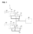
- Fig. 1 is a schematical block diagram of an exemplary embodiment of a fuel injection system for supplying fuel at a high-pressure to an internal combustion engine
- Fig. 2 is system diagram of a further exemplary embodiment of a fuel injection system comprising two high-pressure fuel pumps,
- Fig. 3 is a flow chart of an exemplary embodiment of a method for controlling at least two high-pressure fuel pumps for pumping fuel at a high pressure into a high-pressure fuel distribution line system connected with an internal combustion engine, and
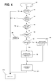
- Fig. 4 is a flow chart of another exemplary embodiment of a method for controlling at least two high-pressure fuel pumps for pumping fuel at a high pressure into a high-pressure fuel distribution line system connected with an internal combustion engine.
- the fuel injection system 5 includes a first high-pressure fuel pump 100 and a second high-pressure fuel pump 200.
- Both high-pressure fuel pumps 100, 200 may be the same type of fuel pump. Accordingly, the basic structure of both fuel pumps 100, 200 may be identical. However, in other exemplary embodiments of a fuel injection system 5, the type or construction of fuel pumps 100, 200 can be different.
- the number of fuel pumps 100, 200 is at least two. Depending on the internal combustion engine and its rated power output, it might be suitable to provide two or more fuel pumps of the same or different type.
- the first high pressure fuel pump 100 includes a pumping element 115, which may include 2 to 4 or even more pistons guided in a piston guide (not shown).
- An intake section 110 may be disposed downstream of the pumping element 115.
- the intake section 110 may include a suction throttle valve or flow control valve 120.
- a return line 125 extends from the pumping element 115 to the intake section 110.
- Fuel at a low pressure is indicated with reference numeral 104.
- Fuel at a high pressure outputted from the high-pressure fuel pump 100 is indicated by reference numeral 105.
- the second high pressure fuel pump 200 may also include a pumping element 215, which may include 2 to 4 or even more pistons guided in a piston guide (not shown).
- An intake section 210 may be disposed downstream of the pumping element 215.
- the intake section 210 may include a flow control valve 220.
- a return line 225 extends from the pumping element 215 to the intake section 210.
- Fuel at a low pressure is indicated with reference numeral 204.
- Fuel at a high pressure outputted from the high-pressure fuel pump 200 is indicated by reference numeral 205.
- Both high-pressure fuel pumps 100, 200 and the associated parts, in particular the flow control valves 120, 220 may be connected with a control unit 400, for example an ECM.
- Fig. 2 shows a system diagram of a fuel injection system 5 incorporating the basic principle of the fuel injection system disclosed in Fig. 1 .
- a low-pressure pump 15 is connected via a fuel supply line 20 with fuel intake sections 110, 210 of the high-pressure fuel pumps 100, 200.
- the pump 15 is connected with the fuel tank 10.
- the high-pressure fuel distribution line system 300 may include a common rail 305.
- the common rail 305 in turn is connected with high-pressure fuel injection nozzles 505.
- the injection nozzles 505 discharge into one or more combustion chambers 510 of an internal combustion engine 500.
- a control unit 400 is connected with the high-pressure fuel pumps 100, 200 and, e.g., with the respective intake sections 110, 210.
- a pressure sensor 405 may be disposed in the common rail 305 and connected with the control unit 400.
- the low-pressure fuel pump 15 pumps fuel 104, 204 at a low pressure from the fuel tank 10 via the fuel line 20 to the intake sections 110, 210 of the high-pressure fuel pumps 100, 200.
- the control unit 400 may adjust the flow control valves 120, 220 in such a manner that the pressure in the common rail 305 detected by the sensor 405 is increased maintained or reduced to a value desired for an actual engine load of the internal combustion engine 500.
- the control unit 400 may control the flow control valves 120, 220 such that the amount of fuel pumped by both high-pressure fuel pumps 100, 200 into the high-pressure distribution line system 300 is required for operation of the engine 500 at the desired actual load.
- the fuel 104, 204 passing through both flow control valves 120, 220 is pumped by the high-pressure fuel pumps 100, 200 to the desired high-pressure value and may flow into the high pressure distribution line system 300 and further into the common rail 305. From the common rail 305 the high-pressure fuel is injected into the combustion chamber 510 of the internal combustion engine 500.
- a low-load pump switch control mode or routine will be explained in detail.
- each of the two high-pressure fuel pumps 100, 200 pumps such a large amount of fuel 105, 205 that the temperature of the pumped mixture of new fuel 104, 204 supplied from the tank 10 and the recycled leaked fuel remains below a critical temperature despite the high temperature of the recycled leaked fuel.
- the predetermined load threshold may be about 5-10 % or 1-20 %, more particularly lower than 2 % or 1 %, even more particularly lower than 1 % or 0.5 % or less, of the maximum load of the internal combustion engine 500.
- each high-pressure fuel pump 100, 200 may heat up. This heating is caused by the fact that the respective amount of fuel leaked from the pumping elements 115, 215 of the high-pressure fuel pump 100, 200 being relatively large in comparison with the amount of new fuel supplied from the pump 15 and originating from the tank 10, which fuel is at a lower temperature.
- step S 1 a low-load pump switch control mode is started.
- the low-load pump switch control mode may correspond to the method disclosed above.
- step S2 it may be checked whether the ECM power has been on for more than five seconds. This query is a standard for ECMs to guarantee that the ECM 400 is operating correctly. In case the ECM 400 has not been powered for a sufficient period, e.g. less then, e.g., five seconds, the process proceeds to step S12. In step 12, the process returns to step S1.
- step S2 In case it is determined in step S2 that the ECM 400 has already been powered for more than the sufficient period, e.g., five seconds, the process continues to step S3. In step S3 it is ensured that all electrical equipment is working correctly, e.g, it is checked that the outputs are without active diagnostics. If all outputs are active, the process proceeds to step S4. Otherwise, the process proceeds to step S12.
- step S4 it is checked whether or not the actual engine load is below a predetermined load threshold.
- the amount of fuel being pumped in each high-pressure fuel pump 100, 200 may be so small that the problem of heating up of parts of the pumping elements 110, 210 of each high-pressure fuel pump 100, 200 may arise.
- step S5 it is checked whether a switch timer or counter is equal to zero. If not, the counter is decremented in step 6. Then the process proceeds to steps S12 and S1. If the counter is already zero, the process proceeds to step S7.
- the pump output of the first high-pressure fuel pump 100 e.g. pump output 1 according to Fig 3
- first amount of fuel first amount of fuel
- step S8 the pump output of the high-pressure fuel pump 100 (in Fig. 3 : pump output 1) is ramped down to zero or to a small amount of fuel. This may mean that the flow control valve 120 of the first high-pressure fuel pump 100 will be gradually closed or nearly closed within a predetermined time period. Consequently, the amount of fuel pumped in the pumping element 115 of the first high-pressure fuel pump 100 is about zero or is only a small amount of fuel (for example corresponding to the fuel leaked from the pumping element 115). Then, the process proceeds to method step S 11.
- step 11 the counter is set, i.e. the first time period starts now. Then, the process proceeds to method steps S12 and in turn to S1. Again, in method step S5 it is checked whether the counter is zero or not. Due to the fact that the counter was started in step S11, the counter is not zero when step 5 is reacted again. Therefore, the process proceeds to step S6. The cycle including the method steps S 1 to S5 and S6 continuous to as long as the counter again becomes zero, i.e. the first time period is finished.
- the process proceeds to method step S7. Due to the fact that the pump output of the first high-pressure fuel pump 100 is currently zero or small, the process proceeds to method step S9. Accordingly, the pump output of the second high-pressure fuel pump 200 (in Fig. 3 pump output 2) is ramped down to zero or to a small amount of fuel.
- the ramping function for the second fuel pump 200 can be the same as the ramping function of the first high-pressure fuel pump 100. In another exemplary embodiment, the ramp-down function may be different.
- the process proceeds to method step S10. Accordingly, the pump output of the first high-pressure fuel pump 100 (in Fig. 3 pump output 1) is ramped up such that the second amount of fuel is pumped by the high-pressure fuel pump 100 to operate the internal combustion engine 500 at the desired low load (normal mode). Thereafter, in method step S11, the counter may be set again to a preset switch time period (in Fig. 3 . switch time), e.g., the time period after one or more pumps are switched from one mode into another mode.
- a preset switch time period in Fig. 3 . switch time
- step S8 the pump output of the high-pressure pump 100 (in Fig 3 pump output 1) is ramped down again.
- the switching between the two pump modes of the two high-pressure fuel pumps 100, 200 in accordance to the above-mentioned cycle, including method steps S1-S12, is active as long as the actual engine load is lower than the predetermined load threshold. Otherwise, the two high-pressure fuel pumps 100, 200 operate and pumps as to operate the internal combustion engine 500 at the desired load.
- the above method also may be applied to more than two high-pressure fuel pumps 100, 200.
- at least one of the total number of high-pressure fuel pumps 100, 200 operates in the first pump mode and at least one of the other fuel pumps 100, 200 operates in the second pump mode.
- all other high-pressure fuel pump(s) 100, 200 will run in the second pump mode except the high-pressure fuel pumps running in the first pump mode.
- a PID controller 600 (proportional-integral-derivative controller) operates the flow control valves 120, 220 in real time based on the pressure in the common rail 305 detected by the pressure sensor 405.
- the PID controller 600 is a commonly-available control loop feedback mechanism available for industrial control systems.
- the PID controller 600 may attempt to correct any deviation between a measured process variable and a desired setpoint by calculating and then outputting a corrective value that can adjust the process accordingly.
- the process variable may be the pressure in the common rail 405.
- This process control of the flow control valves 120, 220 may be temporarily suspended for one of the two high-pressure fuel pumps 100, 200 by the method described above and shown in Fig. 4 .
- step S8 the flow control valve 120 of the first high-pressure fuel pump 100 is adjusted such that no fuel or only a small amount of fuel can pass and be pumped by the pumping element 115. Due to the PID process control, the other flow control valve 220 of the second high-pressure fuel pump 200 is automatically adjusted by the PID controller such that more fuel will be pumped via the second high-pressure fuel pump 200 in order to maintain the desired pressure in the common rail 305. As long as the pump output 1 of the first high-pressure fuel pump 100 in accordance with the steps S2-S6 is zero or very low and does not change, the second high-pressure fuel pump 200 is controlled in accordance with the PID process control.
- the first flow control valve of the first high-pressure fuel pump 100 is again controlled in accordance with the PID process control.
- the process shown in Fig. 4 illustrates that, according to this exemplary embodiment of the present disclosure, the flow control valves 120, 220 are integrated in a PID process control. However, in case the actual engine load is lower than the engine threshold, alternately one of the two flow control valves 120, 220 is actively adjusted for the first or second time period such that zero or a small amount of fuel passes therethrough.
- first amount of fuel may mean that e.g. 30 %, or 20 % or 10 % or 5 % or 1 % or 0.5% or 0.1 % or 0.01% or 0.001 % or less of the maximum amount of fuel pumped by the high-pressure fuel pump 100, 200 passes through the corresponding flow control valve 120, 220. All intermediate percentage between about 30 % and 0.0 % are expressly included in this disclosure.
- the first amount of fuel may be any percentage between about 30 % to 0 % of the second amount of fuel.
- the expression “amount of fuel” used above may be replaced by the expression “rate of fuel”. Accordingly, the expression “first amount of fuel” may be replaced by “first rate of fuel” and “second amount of fuel” may be replaced by “second rate of fuel”.
- the fuel pumps in case an actual engine load is below a set load threshold, the fuel pumps may be operated in a low load pump switch control mode. Accordingly, a high-pressure fuel pump may heat up during operation in the first pump mode and a high-pressure fuel pump may heat up less or even cool down during operation in the second pump mode. Due to the switching of the high-pressure fuel pumps between the first and second pump modes, the average temperature of the high-pressure fuel pumps might be higher than when the high-pressure fuel pumps are operated with large flow rates, but all high-pressure fuel pumps may nevertheless remain in tolerable temperature ranges even during idling.
- An advantage of certain preferred embodiments may be that the basic arrangement of the fuel injection system is not required to be changed.
- a control unit may be easily modified without undue efforts and, hence, with relatively low costs.
- the above-described system may be controlled by looking at the load on the engine.
- the system may be controlled by measuring temperatures, e.g., a pump temperature.
Priority Applications (7)
| Application Number | Priority Date | Filing Date | Title |
|---|---|---|---|
| EP08001853A EP2085603A1 (fr) | 2008-01-31 | 2008-01-31 | Système et procédé pour éviter la surchauffe de pompe CR |
| PCT/EP2008/010125 WO2009095053A1 (fr) | 2008-01-31 | 2008-11-28 | Système et procédé de prévention de surchauffe de pompe à carburant |
| US12/864,861 US8307810B2 (en) | 2008-01-31 | 2008-11-28 | System and method for preventing overheating of a fuel pump |
| AT08871700T ATE524648T1 (de) | 2008-01-31 | 2008-11-28 | System und verfahren zur verhinderung der überhitzung einer brennstoffpumpe |
| EP08871700A EP2235352B1 (fr) | 2008-01-31 | 2008-11-28 | Système et procédé de prévention de surchauffe de pompe à carburant |
| ES08871700T ES2373077T3 (es) | 2008-01-31 | 2008-11-28 | Sistema y método para prevenir el sobrecalentamiento de una bomba de combustible. |
| CN200880126092.0A CN101925732B (zh) | 2008-01-31 | 2008-11-28 | 防止燃料泵过热的系统及方法 |
Applications Claiming Priority (1)
| Application Number | Priority Date | Filing Date | Title |
|---|---|---|---|
| EP08001853A EP2085603A1 (fr) | 2008-01-31 | 2008-01-31 | Système et procédé pour éviter la surchauffe de pompe CR |
Publications (1)
| Publication Number | Publication Date |
|---|---|
| EP2085603A1 true EP2085603A1 (fr) | 2009-08-05 |
Family
ID=39493336
Family Applications (2)
| Application Number | Title | Priority Date | Filing Date |
|---|---|---|---|
| EP08001853A Withdrawn EP2085603A1 (fr) | 2008-01-31 | 2008-01-31 | Système et procédé pour éviter la surchauffe de pompe CR |
| EP08871700A Active EP2235352B1 (fr) | 2008-01-31 | 2008-11-28 | Système et procédé de prévention de surchauffe de pompe à carburant |
Family Applications After (1)
| Application Number | Title | Priority Date | Filing Date |
|---|---|---|---|
| EP08871700A Active EP2235352B1 (fr) | 2008-01-31 | 2008-11-28 | Système et procédé de prévention de surchauffe de pompe à carburant |
Country Status (6)
| Country | Link |
|---|---|
| US (1) | US8307810B2 (fr) |
| EP (2) | EP2085603A1 (fr) |
| CN (1) | CN101925732B (fr) |
| AT (1) | ATE524648T1 (fr) |
| ES (1) | ES2373077T3 (fr) |
| WO (1) | WO2009095053A1 (fr) |
Cited By (3)
| Publication number | Priority date | Publication date | Assignee | Title |
|---|---|---|---|---|
| WO2014206768A1 (fr) * | 2013-06-26 | 2014-12-31 | Robert Bosch Gmbh | Pompe haute pression et système d'injection de carburant pourvu d'une pompe haute pression |
| CN106089738A (zh) * | 2016-08-16 | 2016-11-09 | 李川凌 | 一种智能恒压燃料泵 |
| EP2999879A4 (fr) * | 2013-05-23 | 2017-02-15 | Scania CV AB | Procédé et dispositif permettant le fonctionnement d'une pompe à carburant haute pression |
Families Citing this family (14)
| Publication number | Priority date | Publication date | Assignee | Title |
|---|---|---|---|---|
| ZA200306564B (en) * | 2001-02-26 | 2004-10-15 | Optinose As | Nasal devices. |
| DE102005005446A1 (de) * | 2005-02-04 | 2006-08-10 | Grünenthal GmbH | Bruchfeste Darreichungsformen mit retardierter Freisetzung |
| NO330187B1 (no) * | 2008-05-08 | 2011-03-07 | Hamworthy Gas Systems As | Gasstilforselssystem for gassmotorer |
| US20120070108A1 (en) * | 2010-09-17 | 2012-03-22 | Leonid Kashchenevsky | Hydrostatic arrangement for a spin welding machine and method of supporting spindle for the same |
| US8789513B2 (en) * | 2011-09-26 | 2014-07-29 | Hitachi, Ltd | Fuel delivery system |
| DE102012218643B4 (de) * | 2012-10-12 | 2020-07-09 | Vitesco Technologies GmbH | Kraftstoffeinspritzsystem für eine Brennkraftmaschine und Verfahren zum Betreiben eines solchen Kraftstoffeinspritzsystems |
| US20140331974A1 (en) * | 2013-05-08 | 2014-11-13 | Caterpillar Inc. | Modular Low Pressure Fuel System with Filtration |
| US9587581B2 (en) * | 2013-06-20 | 2017-03-07 | GM Global Technology Operations LLC | Wideband diesel fuel rail control using active pressure control valve |
| US9506417B2 (en) * | 2014-04-17 | 2016-11-29 | Ford Global Technologies, Llc | Methods for detecting high pressure pump bore wear |
| EP3093469B1 (fr) * | 2015-05-13 | 2020-11-11 | Caterpillar Motoren GmbH & Co. KG | Système d'alimentation en carburant pour un moteur à combustion interne |
| US10451013B2 (en) * | 2015-08-20 | 2019-10-22 | Ford Global Technologies, Llc | Method for operating a dual lift pump system |
| GB2557556A (en) * | 2015-11-25 | 2018-06-20 | Walmart Apollo Llc | Unmanned aerial delivery to secure location |
| DE102016213595A1 (de) * | 2016-07-25 | 2018-01-25 | Robert Bosch Gmbh | Kraftstofffördereinrichtung für eine Brennkraftmaschine, sowie ein Verfahren zur Förderung von Kraftstoff in einer Kraftstofffördereinrichtung |
| JP2019100214A (ja) * | 2017-11-29 | 2019-06-24 | トヨタ自動車株式会社 | 内燃機関の燃料ポンプ制御装置 |
Citations (6)
| Publication number | Priority date | Publication date | Assignee | Title |
|---|---|---|---|---|
| EP0204981A2 (fr) * | 1985-06-08 | 1986-12-17 | Robert Bosch Gmbh | Procédé pour le fonctionnement sûr d'un moteur à combustion interne |
| JPH0374564A (ja) * | 1989-08-11 | 1991-03-29 | Japan Electron Control Syst Co Ltd | 燃料ポンプ制御装置 |
| DE19501475A1 (de) | 1995-01-19 | 1996-07-25 | Bosch Gmbh Robert | Kraftstoffeinspritzvorrichtung für einen Verbrennungsmotor |
| EP1167731A2 (fr) | 2000-06-20 | 2002-01-02 | Robert Bosch Gmbh | Méthode pour surveiller le fonctionnement de pompes pour véhicules ayant au moins deux pompes électriques à carburant |
| WO2005106239A1 (fr) * | 2004-04-28 | 2005-11-10 | Toyota Jidosha Kabushiki Kaisha | Appareil d'alimentation en carburant pour moteur a combustion interne |
| WO2007135545A1 (fr) * | 2006-05-23 | 2007-11-29 | Toyota Jidosha Kabushiki Kaisha | Appareil et méthode de commande destinés à un moteur à combustion interne et appareil et méthode de détermination des propriétés d'un carburant |
Family Cites Families (12)
| Publication number | Priority date | Publication date | Assignee | Title |
|---|---|---|---|---|
| DE3422829A1 (de) | 1984-06-20 | 1986-01-02 | Robert Bosch Gmbh, 7000 Stuttgart | Schaltungsanordnung zur ansteuerung von elektrischen kraftstoffpumpen |
| JP3033214B2 (ja) * | 1991-02-27 | 2000-04-17 | 株式会社デンソー | 複数の燃料圧送手段による蓄圧式燃料供給方法及び装置と、複数の流体圧送手段を有する機器における異常判断装置 |
| US5357929A (en) * | 1993-09-29 | 1994-10-25 | Navistar International Transportation Corp. | Actuation fluid pump for a unit injector system |
| JP3304755B2 (ja) * | 1996-04-17 | 2002-07-22 | 三菱電機株式会社 | 燃料噴射装置 |
| DE19646581A1 (de) * | 1996-11-12 | 1998-05-14 | Bosch Gmbh Robert | Kraftstoffeinspritzsystem |
| JP3074564B2 (ja) * | 1997-11-14 | 2000-08-07 | 山崎製パン株式会社 | 搬送コンベア用搬送物体の列分け装置 |
| DE10023033A1 (de) * | 2000-05-11 | 2001-11-22 | Bosch Gmbh Robert | Verfahren zum Betreiben eines Kraftstoffzumesssystems einer direkteinspritzenden Brennkraftmaschine |
| DE10157641C2 (de) | 2001-11-24 | 2003-09-25 | Mtu Friedrichshafen Gmbh | Verfahren zur Steuerung einer Brennkraftmaschine |
| JP4123952B2 (ja) | 2003-02-06 | 2008-07-23 | トヨタ自動車株式会社 | 内燃機関の燃料供給システム |
| DE10335698A1 (de) | 2003-08-05 | 2005-02-24 | Bayerische Motoren Werke Ag | Kraftstoffversorgungsanlage einer Brennkraftmaschine sowie Betriebsverfahren hierfür |
| US20080115770A1 (en) * | 2006-11-16 | 2008-05-22 | Merchant Jack A | Pump with torque reversal avoidance feature and engine system using same |
| JP4672640B2 (ja) * | 2006-11-30 | 2011-04-20 | 三菱重工業株式会社 | エンジンの燃料噴射装置及び運転方法 |
-
2008
- 2008-01-31 EP EP08001853A patent/EP2085603A1/fr not_active Withdrawn
- 2008-11-28 CN CN200880126092.0A patent/CN101925732B/zh active Active
- 2008-11-28 EP EP08871700A patent/EP2235352B1/fr active Active
- 2008-11-28 US US12/864,861 patent/US8307810B2/en active Active
- 2008-11-28 AT AT08871700T patent/ATE524648T1/de not_active IP Right Cessation
- 2008-11-28 WO PCT/EP2008/010125 patent/WO2009095053A1/fr active Application Filing
- 2008-11-28 ES ES08871700T patent/ES2373077T3/es active Active
Patent Citations (6)
| Publication number | Priority date | Publication date | Assignee | Title |
|---|---|---|---|---|
| EP0204981A2 (fr) * | 1985-06-08 | 1986-12-17 | Robert Bosch Gmbh | Procédé pour le fonctionnement sûr d'un moteur à combustion interne |
| JPH0374564A (ja) * | 1989-08-11 | 1991-03-29 | Japan Electron Control Syst Co Ltd | 燃料ポンプ制御装置 |
| DE19501475A1 (de) | 1995-01-19 | 1996-07-25 | Bosch Gmbh Robert | Kraftstoffeinspritzvorrichtung für einen Verbrennungsmotor |
| EP1167731A2 (fr) | 2000-06-20 | 2002-01-02 | Robert Bosch Gmbh | Méthode pour surveiller le fonctionnement de pompes pour véhicules ayant au moins deux pompes électriques à carburant |
| WO2005106239A1 (fr) * | 2004-04-28 | 2005-11-10 | Toyota Jidosha Kabushiki Kaisha | Appareil d'alimentation en carburant pour moteur a combustion interne |
| WO2007135545A1 (fr) * | 2006-05-23 | 2007-11-29 | Toyota Jidosha Kabushiki Kaisha | Appareil et méthode de commande destinés à un moteur à combustion interne et appareil et méthode de détermination des propriétés d'un carburant |
Cited By (4)
| Publication number | Priority date | Publication date | Assignee | Title |
|---|---|---|---|---|
| EP2999879A4 (fr) * | 2013-05-23 | 2017-02-15 | Scania CV AB | Procédé et dispositif permettant le fonctionnement d'une pompe à carburant haute pression |
| US9863386B2 (en) | 2013-05-23 | 2018-01-09 | Scania Cv Ab | Method and device for operation of a high pressure fuel pump |
| WO2014206768A1 (fr) * | 2013-06-26 | 2014-12-31 | Robert Bosch Gmbh | Pompe haute pression et système d'injection de carburant pourvu d'une pompe haute pression |
| CN106089738A (zh) * | 2016-08-16 | 2016-11-09 | 李川凌 | 一种智能恒压燃料泵 |
Also Published As
| Publication number | Publication date |
|---|---|
| EP2235352A1 (fr) | 2010-10-06 |
| WO2009095053A1 (fr) | 2009-08-06 |
| CN101925732B (zh) | 2013-06-12 |
| ES2373077T3 (es) | 2012-01-31 |
| EP2235352B1 (fr) | 2011-09-14 |
| US8307810B2 (en) | 2012-11-13 |
| US20110023830A1 (en) | 2011-02-03 |
| CN101925732A (zh) | 2010-12-22 |
| ATE524648T1 (de) | 2011-09-15 |
Similar Documents
| Publication | Publication Date | Title |
|---|---|---|
| EP2085603A1 (fr) | Système et procédé pour éviter la surchauffe de pompe CR | |
| US6578555B2 (en) | Control method | |
| EP1519031B1 (fr) | Dispositif pour réguler l'écoulement d'une pompe à haute pression dans un système d'injection de carburant à rampe d'alimentation commune d'un moteur à combustion interne | |
| EP2010776B1 (fr) | Dispositif de commande de démarrage et procédé de commande de démarrage pour moteur à combustion interne | |
| US7487761B1 (en) | Detection of fuel system problems | |
| US7284539B1 (en) | Fuel pressure controller for direct injection internal combustion engine | |
| US7431018B2 (en) | Fuel injection system monitoring abnormal pressure in inlet of fuel pump | |
| US20050188958A1 (en) | Arrangement for supplying fuel to the fuel injectors of an internal combustion engine | |
| JP2002541383A (ja) | 内燃機関の制御方法及び装置 | |
| JP2010106732A (ja) | 筒内噴射式の内燃機関の制御装置 | |
| JP2007303372A (ja) | 内燃機関の燃料供給システム | |
| JP2003239794A (ja) | 蓄圧式燃料噴射装置 | |
| US7814887B2 (en) | Method and device for controlling a pump connected to a fuel rail | |
| JP6197775B2 (ja) | 減量弁の異常判定装置 | |
| JP4155168B2 (ja) | コモンレール式燃料噴射装置 | |
| WO2013018131A1 (fr) | Dispositif d'alimentation en carburant | |
| JP2010216370A (ja) | 燃料供給制御装置 | |
| JP3900903B2 (ja) | 蓄圧式燃料噴射装置 | |
| JP4566450B2 (ja) | 蓄圧式燃料噴射装置 | |
| JP2003148229A (ja) | 蓄圧式燃料噴射装置 | |
| JP4442441B2 (ja) | 内燃機関用燃料噴射装置 | |
| JP4062721B2 (ja) | 蓄圧式燃料噴射装置 | |
| JP4650458B2 (ja) | サプライポンプの制御装置 | |
| JP2004036563A (ja) | コモンレール式燃料噴射システム | |
| JP7392628B2 (ja) | 燃圧制御システム |
Legal Events
| Date | Code | Title | Description |
|---|---|---|---|
| PUAI | Public reference made under article 153(3) epc to a published international application that has entered the european phase |
Free format text: ORIGINAL CODE: 0009012 |
|
| AK | Designated contracting states |
Kind code of ref document: A1 Designated state(s): AT BE BG CH CY CZ DE DK EE ES FI FR GB GR HR HU IE IS IT LI LT LU LV MC MT NL NO PL PT RO SE SI SK TR |
|
| AX | Request for extension of the european patent |
Extension state: AL BA MK RS |
|
| AKX | Designation fees paid | ||
| STAA | Information on the status of an ep patent application or granted ep patent |
Free format text: STATUS: THE APPLICATION IS DEEMED TO BE WITHDRAWN |
|
| 18D | Application deemed to be withdrawn |
Effective date: 20100206 |
|
| REG | Reference to a national code |
Ref country code: DE Ref legal event code: 8566 |
|
| RIN1 | Information on inventor provided before grant (corrected) |
Inventor name: RITSCHER, BERT Inventor name: RESSEL, HORST Inventor name: GNEIST, BODO Inventor name: HAAS, STEFAN Inventor name: SCHICK, JUERGEN Inventor name: SCHEIBE, WOLFGANG |