EP2085298A1 - Kraftfahrzeug mit einer Luftleitvorrichtung - Google Patents
Kraftfahrzeug mit einer Luftleitvorrichtung Download PDFInfo
- Publication number
- EP2085298A1 EP2085298A1 EP09005858A EP09005858A EP2085298A1 EP 2085298 A1 EP2085298 A1 EP 2085298A1 EP 09005858 A EP09005858 A EP 09005858A EP 09005858 A EP09005858 A EP 09005858A EP 2085298 A1 EP2085298 A1 EP 2085298A1
- Authority
- EP
- European Patent Office
- Prior art keywords
- guiding device
- motor vehicle
- vehicle
- air guide
- guide element
- Prior art date
- Legal status (The legal status is an assumption and is not a legal conclusion. Google has not performed a legal analysis and makes no representation as to the accuracy of the status listed.)
- Granted
Links
Images

Classifications
-
- B—PERFORMING OPERATIONS; TRANSPORTING
- B62—LAND VEHICLES FOR TRAVELLING OTHERWISE THAN ON RAILS
- B62D—MOTOR VEHICLES; TRAILERS
- B62D35/00—Vehicle bodies characterised by streamlining
- B62D35/007—Rear spoilers
-
- B—PERFORMING OPERATIONS; TRANSPORTING
- B62—LAND VEHICLES FOR TRAVELLING OTHERWISE THAN ON RAILS
- B62D—MOTOR VEHICLES; TRAILERS
- B62D37/00—Stabilising vehicle bodies without controlling suspension arrangements
- B62D37/02—Stabilising vehicle bodies without controlling suspension arrangements by aerodynamic means
-
- B—PERFORMING OPERATIONS; TRANSPORTING
- B62—LAND VEHICLES FOR TRAVELLING OTHERWISE THAN ON RAILS
- B62D—MOTOR VEHICLES; TRAILERS
- B62D37/00—Stabilising vehicle bodies without controlling suspension arrangements
-
- Y—GENERAL TAGGING OF NEW TECHNOLOGICAL DEVELOPMENTS; GENERAL TAGGING OF CROSS-SECTIONAL TECHNOLOGIES SPANNING OVER SEVERAL SECTIONS OF THE IPC; TECHNICAL SUBJECTS COVERED BY FORMER USPC CROSS-REFERENCE ART COLLECTIONS [XRACs] AND DIGESTS
- Y02—TECHNOLOGIES OR APPLICATIONS FOR MITIGATION OR ADAPTATION AGAINST CLIMATE CHANGE
- Y02T—CLIMATE CHANGE MITIGATION TECHNOLOGIES RELATED TO TRANSPORTATION
- Y02T10/00—Road transport of goods or passengers
- Y02T10/80—Technologies aiming to reduce greenhouse gasses emissions common to all road transportation technologies
- Y02T10/82—Elements for improving aerodynamics
-
- Y—GENERAL TAGGING OF NEW TECHNOLOGICAL DEVELOPMENTS; GENERAL TAGGING OF CROSS-SECTIONAL TECHNOLOGIES SPANNING OVER SEVERAL SECTIONS OF THE IPC; TECHNICAL SUBJECTS COVERED BY FORMER USPC CROSS-REFERENCE ART COLLECTIONS [XRACs] AND DIGESTS
- Y10—TECHNICAL SUBJECTS COVERED BY FORMER USPC
- Y10S—TECHNICAL SUBJECTS COVERED BY FORMER USPC CROSS-REFERENCE ART COLLECTIONS [XRACs] AND DIGESTS
- Y10S180/00—Motor vehicles
- Y10S180/903—Airstream reactive vehicle or vehicle structure
Definitions
- the invention relates to a motor vehicle having an air guiding device for a vehicle, in particular a passenger car, according to the preamble of patent claim 1.
- a spoiler for a vehicle in particular passenger car out, which is disposed in an upper rear portion of the vehicle and comprises an air guide, which is displaceable from a rest position, in which it is flush with the shape of the rear area, in an extended operating position.
- the spoiler is formed in this arrangement by a reversed one-piece wing, which is movable by means of an actuator from the rest position to the operating position and vice versa.
- the DE 43 05 090 C2 discloses an air guiding device for a vehicle, which is arranged in a rear region of the vehicle and comprises an air guiding element, which can be displaced from a rest position into an extended operating position.
- the spoiler is formed by a rear spoiler, which is arranged in a recessed receptacle of the vehicle body and displaceable by means of an actuator from a retracted rest position in which it is approximately flush with the adjacent vehicle body, in an extended operating position.
- the integrally formed air guide element has in the rest position and in the extended operating position in each case the same transverse extent.
- the object of the invention is to develop a motor vehicle with a spoiler of the type mentioned so that the aerodynamic properties of the vehicle, especially the output at the rear axle, is further improved.
- a passenger car 1 comprises a body 2 which, in the illustrated rear region 3, has a large-area disk 4 and a body part 5 arranged behind it.
- the rear window 4 and the body part 5 are delimited on both longitudinal sides 6 by a rear side part 7, on which a rear side window 8 is provided.
- a transverse lighting unit 10 connects.
- the body part 5 and the rear window 4 may be formed separately from each other; However, they can also be combined to form a common unit, which is for example mounted pivotably on the body 2.
- the body part 5 is formed by a rear-side engine cover.
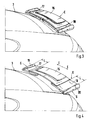
- an air guiding device 11 which comprises an air guiding element 12 cooperating with an actuating device (not shown).
- the spoiler 12 is from a rest position A, in which it is integrated approximately flush with the shape of the rear portion 3, by means of the actuator via intermediate positions B, C in an extended operating position D displaced and vice versa. In the rest position A, the air guide element 12 is received in a recessed receptacle of the rear body part 5, wherein the top of the air guide element 12 extends approximately flush with the adjacent surface contour.
- the spoiler 12 is formed in the embodiment by a swing-rear spoiler 13, which is connected at its front end 14 by mediation of at least one hinge, not shown hinged to the adjacent body part 5. The rear end 15 of the rear spoiler 13 is pivoted when extending the spoiler 1 upwards ( Fig. 2 ).
- displaceable air guide element 12 could also be formed by a reverse airfoil profile (not shown in detail).
- the air guide element 12 in the extended operating position D has a greater transverse extent than in the retracted Rest position A.
- the displaceable air guide element 12 - seen in the vehicle transverse direction EE - is designed in several parts, wherein at least individual parts of the air guiding device 12 are formed movable in the vehicle transverse direction EE.
- the air guide element 12 has a relatively wide central part 16 and two significantly narrower laterally outer extension parts 17, 18, wherein the two lateral extension parts 17, 18 are movable relative to the central part 16 in the vehicle transverse direction EE.
- the two lateral extension parts 17, 18 are at least partially inserted in the retracted rest position A of the air guide 12 in the wider middle part 16.
- the lateral extension parts 17, 18 each have at their outer ends in the vehicle longitudinal direction extending upright boundary webs 19, 20, which project beyond the top of the rear spoiler 13 upwards.
- the lateral extension parts 17, 18 are via a telescopic sliding movement or a folding movement of their retracted end position F ( Fig. 1 u. 2) in its extended end position G ( Fig.
- the second extension movement of the air guide element 12 in the vehicle transverse direction EE can be carried out by an electric motor, pneumatically, hydraulically or the like.
- the two narrow lateral extension parts 17, 18 are almost completely inserted into the wider middle part 16; only the two upright longitudinal boundary webs 19, 20 are located outside of the middle part 16th
- the air guide element 12 comprises two halves, which are pushed in the retracted rest position A in each case partially over a central middle part and in the region of a vehicle center longitudinal plane H-H abut each other. In the fully extended operating position D extends between the diverged halves, the central middle part.
- At the air guide 12 may be provided locally air inlet openings so that cooling air can be passed to a lying behind arranged internal combustion engine.
- the air guide element 12 is moved by a first adjusting movement (pivoting or lifting) of a flush-mounted rest position A in a raised intermediate position B, and then there is a second adjustment movement of the spoiler 12 in the vehicle transverse direction E-E in the extended operating position D.
- the air guide element 12 is widened by the two lateral extension parts 17, 18 on both longitudinal sides in each case by a dimension L.
Landscapes
- Engineering & Computer Science (AREA)
- Mechanical Engineering (AREA)
- Chemical & Material Sciences (AREA)
- Combustion & Propulsion (AREA)
- Transportation (AREA)
- Fluid Mechanics (AREA)
- Physics & Mathematics (AREA)
- Body Structure For Vehicles (AREA)
- Fittings On The Vehicle Exterior For Carrying Loads, And Devices For Holding Or Mounting Articles (AREA)
- Lighting Device Outwards From Vehicle And Optical Signal (AREA)
- Vehicle Body Suspensions (AREA)
- Air-Conditioning For Vehicles (AREA)
- Harvester Elements (AREA)
- Platform Screen Doors And Railroad Systems (AREA)
Abstract
Description
- Die Erfindung betrifft ein Kraftfahrzeug mit einer Luftleitvorrichtung für ein Fahrzeug, insbesondere Personenwagen, gemäß dem Oberbegriff des Patentanspruchs 1.
- Aus der
DE 30 19 150 C2 geht eine Luftleitvorrichtung für ein Fahrzeug, insbesondere Personenwagen hervor, die in einem oben liegenden Heckbereich des Fahrzeuges angeordnet ist und ein Luftleitelement umfasst, das von einer Ruhestellung, in der es oberflächenbündig in den Formverlauf des Heckbereichs integriert ist, in eine ausgefahrene Betriebsstellung verlagerbar ist. - Das Luftleitelement wird bei dieser Anordnung durch einen umgekehrten einstückigen Tragflügel gebildet, der mittels einer Betätigungseinrichtung von der Ruhestellung in die Betriebsstellung bewegbar ist und umgekehrt.
- Die
DE 43 05 090 C2 offenbart eine Luftleitvorrichtung für ein Fahrzeug, die in einem Heckbereich des Fahrzeugs angeordnet ist und ein Luftleitelement umfasst, das von einer Ruhestellung in eine ausgefahrene Betriebsstellung verlagerbar ist. Das Luftleitelement wird durch einen Heckspoiler gebildet, der in einer versenkten Aufnahme der Fahrzeugkarosserie angeordnet und mittels einer Betätigungseinrichtung von einer eingefahrenen Ruhestellung, in der er etwa oberflächenbündig mit der angrenzenden Fahrzeugkarosserie verläuft, in eine ausgefahrene Betriebsstellung verlagerbar ist. - Das einteilig ausgebildete Luftleitelement weist in der Ruhestellung und in der ausgefahrenen Betriebsstellung jeweils dieselbe Quererstreckung auf. Mit den eingangs beschriebenen Luftleitvorrichtungen wird der Luftwiderstandsbeiwert des Fahrzeuges (cw-Wert) verbessert und ein Abtrieb an der Hinterachse erzeugt.
- Aufgabe der Erfindung ist es, ein Kraftfahrzeug mit einer Luftleitvorrichtung der eingangs genannten Gattung so weiterzubilden, dass die aerodynamischen Eigenschaften des Fahrzeuges, insbesondere der Abtrieb an der Hinterachse, noch weiter verbessert wird.
- Erfindungsgemäß wird diese Aufgabe durch die Merkmale des Anspruchs 1 gelöst. Weitere die Erfindung in vorteilhafter Weise ausgestaltende Merkmale enthalten die Unteransprüche.
- Die mit der Erfindung hauptsächlich erzielten Vorteile sind darin zu sehen, dass durch die Vergrößerung des Luftleitelements in Fahrzeugquerrichtung die wirksame aerodynamische Anströmfläche in der Betriebsstellung D vergrößert wird, wodurch insbesondere der Abtrieb des Fahrzeuges an der Hinterachse im Fahrbetrieb weiter erhöht wird. Das Luftleitelement erstreckt sich in der Betriebsstellung D nun auch beiderseits des mittigen Karosserieteils im Bereich der Seitenteile bzw. Kotflügel des Fahrzeuges.
- Die Zeichnung zeigt ein Ausführungsbeispiel der Erfindung, das im folgenden näher beschrieben wird.
-
- Fig. 1
- eine perspektivische Ansicht von schräg vorne auf einen Heckbereich eines Fahrzeuges mit einer Luftleitvorrichtung, wobei ein Luftleitelement eine eingefahrene Ruhestellung A einnimmt,
- Fig. 2
- eine Ansicht entsprechend
Fig. 1 , wobei das Luftleitelement eine hochgeschwenkte Zwischenstellung B einnimmt, - Fig. 3
- ein Ansicht entsprechend
Fig. 2 , wobei das Luftleitelement eine teilweise ausgefahrene Zwischenstellung C in Querrichtung einnimmt, - Fig. 4
- eine Ansicht entsprechend
Fig. 2 in der vollständig ausgefahrenen Betriebsstellung D des Luftleitelements. - Ein Personenwagen 1 umfasst einen Aufbau 2, der im dargestellten Heckbereich 3 eine großflächige Scheibe 4 und ein dahinter liegend angeordnetes Karosserieteil 5 aufweist. Die Heckscheibe 4 und das Karosserieteil 5 sind an beiden Längsseiten 6 jeweils durch ein hinteres Seitenteil 7 begrenzt, an dem ein Fondseitenfenster 8 vorgesehen ist. An das hintere Ende 9 des Seitenteiles 7 schließt sich eine quer verlaufende Leuchteneinheit 10 an. Das Karosserieteil 5 und die Heckscheibe 4 können getrennt voneinander ausgebildet sein; sie können jedoch auch zu einer gemeinsamen Baueinheit zusammengefasst sein, die beispielsweise schwenkbar am Aufbau 2 gelagert ist. Im Ausführungsbeispiel wird das Karosserieteil 5 durch einen heckseitigen Motordeckel gebildet.
- Am heckseitigen Karosserieteil 5 des fließheckartig ausgebildeten Heckbereichs 3 ist eine Luftleitvorrichtung 11 vorgesehen, die ein mit einer nicht näher dargestellten Betätigungseinrichtung zusammenwirkendes Luftleitelement 12 umfasst. Das Luftleitelement 12 ist von einer Ruhestellung A, in der es in den Formverlauf des Heckbereichs 3 etwa oberflächenbündig integriert ist, mittels der Betätigungseinrichtung über Zwischenstellungen B, C in eine ausgefahrene Betriebsstellung D verlagerbar und umgekehrt. In der Ruhestellung A ist das Luftleitelement 12 in einer versenkten Aufnahme des heckseitigen Karosserieteils 5 aufgenommen, wobei die Oberseite des Luftleitelements 12 etwa oberflächenbündig mit der angrenzenden Aufbaukontur verläuft. Das Luftleitelement 12 wird im Ausführungsbeispiel durch einen ausschwenkbaren Heckspoiler 13 gebildet, der an seinem vorne liegenden Ende 14 unter Vermittlung zumindest eines nicht näher dargestellten Scharniers gelenkig mit dem angrenzenden Karosserieteil 5 verbunden ist. Das hintere Ende 15 des Heckspoilers 13 wird beim Ausfahren der Luftleitvorrichtung 1 nach oben geschwenkt (
Fig. 2 ). - Das verlagerbare Luftleitelement 12 könnte jedoch auch durch ein umgekehrtes Tragflügelprofil gebildet werden (nicht näher dargestellt).
- Erfindungsgemäß ist vorgesehen, dass das Luftleitelement 12 in der ausgefahrenen Betriebsstellung D eine größere Quererstreckung aufweist als in der eingefahrenen Ruhestellung A. Erzielt wird dies dadurch, dass das verlagerbare Luftleitelement 12 - in Fahrzeugquerrichtung E-E gesehen - mehrteilig ausgebildet ist, wobei zumindest einzelne Teile der Luftleitvorrichtung 12 in Fahrzeugquerrichtung E-E bewegbar ausgebildet sind.
- Gemäß einer ersten Ausführungsform weist das Luftleitelement 12 ein relativ breites Mittelteil 16 und zwei deutlich schmälere seitlich außenliegende Verlängerungsteile 17, 18 auf, wobei die beiden seitlichen Verlängerungsteile 17, 18 gegenüber dem Mittelteil 16 in Fahrzeugquerrichtung E-E bewegbar sind. Die beiden seitlichen Verlängerungsteile 17, 18 sind in der eingefahrenen Ruhestellung A des Luftleitelements 12 zumindest bereichsweise in das breitere Mittelteil 16 eingeschoben. Im Ausführungsbeispiel weisen die seitlichen Verlängerungsteile 17, 18 an ihren äußeren Enden jeweils in Fahrzeuglängsrichtung verlaufende aufrecht ausgerichtete Begrenzungsstege 19, 20 auf, die die Oberseite des Heckspoilers 13 nach oben hin überragen. Die seitlichen Verlängerungsteile 17, 18 sind über eine teleskopartige Schiebebewegung oder eine Klappbewegung von ihrer eingefahrenen Endstellung F (
Fig. 1 u. 2) in ihre ausgefahrene Endstellung G (Fig. 4 ) verlagerbar und zwar über eine nicht näher dargestellte Antriebseinrichtung. Diese Verstellbewegung der seitlichen Verlängerungsteile 17, 18 in Fahrzeugquerrichtung erfolgt erst dann, wenn das komplette Luftleitelement 12 von der eingefahrenen Ruhestellung A in eine angehobene Zwischenstellung B bewegt wurde. InFig. 3 sind die seitlichen Verlängerungsteile 17, 18 teilweise ausgefahren, wogegenFig. 4 die vollständig ausgefahrene Betriebsstellung D des Luftleitelements 12 zeigt, d.h., die seitlichen Verlängerungsteile 17, 18 sind nun vollständig in Fahrzeugquerrichtung E-E ausgefahren und die Luftleitvorrichtung 11 weist eine größere Quererstreckung auf. - Die zweite Ausfahrbewegung des Luftleitelements 12 in Fahrzeugquerrichtung E-E kann elektromotorisch, pneumatisch, hydraulisch oder dergleichen erfolgen. In der Ruhestellung A sind die beiden schmalen seitlichen Verlängerungsteile 17, 18 nahezu vollständig in das breitere Mittelteil 16 eingeschoben; lediglich die beiden aufrechten längsgerichteten Begrenzungsstege 19, 20 befinden sich außerhalb des Mittelteiles 16.
- Es müssen jedoch keine Begrenzungsstege 19, 20 an den Verlängerungsteilen 17, 18 vorgesehen sein.
- Gemäß einer zweiten, nicht näher dargestellten Ausführungsform umfasst das Luftleitelement 12 zwei Hälften, die in der eingefahrenen Ruhestellung A jeweils bereichsweise über ein zentrales Mittelteil geschoben sind und im Bereich einer Fahrzeugmittellängsebene H-H aneinander anliegen. In der vollständig ausgefahrenen Betriebsstellung D erstreckt sich zwischen den auseinander geschobenen Hälften das zentrale Mittelteil.
- Am Luftleitelement 12 können örtlich Lufteintrittsöffnungen vorgesehen sein, damit Kühlluft zu einer dahinter liegend angeordneten Brennkraftmaschine geleitet werden kann.
- Bei der erfindungsgemäßen Anordnung wird das Luftleitelement 12 über eine erste Verstellbewegung (Verschwenken oder Anheben) von einer außenhautbündigen Ruhestellung A in eine angehobene Zwischenstellung B bewegt, und danach erfolgt eine zweite Verstellbewegung des Luftleitelements 12 in Fahrzeugquerrichtung E-E in die ausgefahrene Betriebsstellung D.
- In der ausgefahrenen Betriebsstellung D wird das Luftleitelement 12 durch die beiden seitlichen Verlängerungsteile 17, 18 an beiden Längsseiten jeweils um ein Maß L verbreitert.
Claims (8)
- Kraftfahrzeug mit einer Luftleitvorrichtung, insbesondere Personenwagen, die in einem Heckbereich des Fahrzeuges angeordnet ist und ein Luftleitelement umfasst, das von einer Ruhestellung in eine ausgefahrene Betriebsstellung verlagerbar ist, dadurch gekennzeichnet, dass das Luftleitelement (12) in der ausgefahrenen Betriebsstellung (D) eine größere Quererstreckung aufweist als in der eingefahrenen Ruhestellung (A).
- Kraftfahrzeug mit einer Luftleitvorrichtung nach Anspruch 1, dadurch gekennzeichnet, dass das Luftleitelement (12) ein Mittelteil (16) und zwei seitlich außenliegende Verlängerungsteile (17, 18) aufweist, wobei die Verlängerungsteile (17, 18) gegenüber dem Mittelteil (16) in Fahrzeugquerrichtung (E-E) bewegbar sind.
- Kraftfahrzeug mit einer Luftleitvorrichtung nach Anspruch 1 oder 2, dadurch gekennzeichnet, dass eine Verstellbewegung der seitlichen Verlängerungsteile (17, 18) erfolgt, wenn das komplette Luftleitelement (12) - ausgehend von der eingefahrenen Ruhestellung (A) - eine angehobene Zwischenstellung (B) einnimmt.
- Kraftfahrzeug mit einer Luftleitvorrichtung nach Anspruch 1, 2 oder 3, dadurch gekennzeichnet, dass in der ausgefahrenen Betriebsstellung (D) das Luftleitelement (12) durch die beiden seitlichen Verlängerungsteile (17, 18) an beiden Längsseiten jeweils um ein Maß (L) verbreitert ist.
- Kraftfahrzeug mit einer Luftleitvorrichtung nach zumindest einem der Ansprüche 1 oder 4, dadurch gekennzeichnet, dass in der Betriebsstellung (D) des Luftleitelements (12) die wirksame aerodynamische Anströmfläche vergrößert ist.
- Kraftfahrzeug mit einer Luftleitvorrichtung nach einem der vorhergehenden Ansprüche, dadurch gekennzeichnet, dass es ein mittiges Karosserieteil (5) aufweist, das seitlich von hinteren Seitenteilen (7) begrenzt wird und dass das Luftleitelement (12) in der Betriebsstellung (D) sich beiderseits des mittigen Karosserieteils (5) im Bereich der Seitenteile (7) erstreckt.
- Kraftfahrzeug mit einer Luftleitvorrichtung nach Anspruch 1, dadurch gekennzeichnet, dass die Luftleiteinrichtung (2) durch einen ausschwenkbaren Heckspoiler (13) gebildet ist, dessen hinteres Ende (15) beim Ausfahren nach oben schwenkt.
- Kraftfahrzeug mit einer Luftleitvorrichtung nach Anspruch 1, dadurch gekennzeichnet, dass das verlagerbare Luftleitelement (12) als Tragflügel ausgebildet ist.
Applications Claiming Priority (2)
| Application Number | Priority Date | Filing Date | Title |
|---|---|---|---|
| DE102005030203A DE102005030203A1 (de) | 2005-06-29 | 2005-06-29 | Luftleitvorrichtung für ein Fahrzeug |
| EP06009497A EP1738996B1 (de) | 2005-06-29 | 2006-05-09 | Luftleitvorrichtung für ein Fahrzeug |
Related Parent Applications (2)
| Application Number | Title | Priority Date | Filing Date |
|---|---|---|---|
| EP06009497.6 Division | 2006-05-09 | ||
| EP06009497A Division EP1738996B1 (de) | 2005-06-29 | 2006-05-09 | Luftleitvorrichtung für ein Fahrzeug |
Publications (2)
| Publication Number | Publication Date |
|---|---|
| EP2085298A1 true EP2085298A1 (de) | 2009-08-05 |
| EP2085298B1 EP2085298B1 (de) | 2011-03-02 |
Family
ID=37067416
Family Applications (2)
| Application Number | Title | Priority Date | Filing Date |
|---|---|---|---|
| EP06009497A Expired - Lifetime EP1738996B1 (de) | 2005-06-29 | 2006-05-09 | Luftleitvorrichtung für ein Fahrzeug |
| EP09005858A Expired - Lifetime EP2085298B1 (de) | 2005-06-29 | 2006-05-09 | Kraftfahrzeug mit einer Luftleitvorrichtung |
Family Applications Before (1)
| Application Number | Title | Priority Date | Filing Date |
|---|---|---|---|
| EP06009497A Expired - Lifetime EP1738996B1 (de) | 2005-06-29 | 2006-05-09 | Luftleitvorrichtung für ein Fahrzeug |
Country Status (7)
| Country | Link |
|---|---|
| US (1) | US7322638B2 (de) |
| EP (2) | EP1738996B1 (de) |
| JP (1) | JP4817988B2 (de) |
| KR (1) | KR20070001807A (de) |
| CN (1) | CN1891556B (de) |
| AT (2) | ATE438555T1 (de) |
| DE (3) | DE102005030203A1 (de) |
Cited By (3)
| Publication number | Priority date | Publication date | Assignee | Title |
|---|---|---|---|---|
| RU2538510C1 (ru) * | 2012-12-05 | 2015-01-10 | Др. Инж. х.к. Ф. Порше Акциенгезелльшафт | Воздухонаправляющее устройство для задней части транспортного средства |
| DE102021116048A1 (de) | 2021-06-22 | 2022-12-22 | Dr. Ing. H.C. F. Porsche Aktiengesellschaft | Heckspoiler für ein Kraftfahrzeug |
| DE102024105365A1 (de) | 2024-02-27 | 2025-08-28 | Dr. Ing. H.C. F. Porsche Aktiengesellschaft | Heckspoilervorrichtung und Kraftfahrzeug |
Families Citing this family (47)
| Publication number | Priority date | Publication date | Assignee | Title |
|---|---|---|---|---|
| DE102006014263A1 (de) * | 2006-03-28 | 2007-10-04 | Dr.Ing.H.C. F. Porsche Ag | Luftleitvorrichtung für ein Fahrzeug |
| DE102006014264A1 (de) | 2006-03-28 | 2007-10-04 | Dr.Ing.H.C. F. Porsche Ag | Luftleitvorrichtung für ein Fahrzeug |
| DE102006014260A1 (de) | 2006-03-28 | 2007-10-04 | Dr.Ing.H.C. F. Porsche Ag | Luftleitvorrichtung für ein Fahrzeug |
| DE102006014259A1 (de) | 2006-03-28 | 2007-10-11 | Dr.Ing.H.C. F. Porsche Ag | Luftleitvorrichtung für ein Fahrzeug |
| DE102006014261A1 (de) * | 2006-03-28 | 2007-10-04 | Dr.Ing.H.C. F. Porsche Ag | Luftleitvorrichtung für ein Fahrzeug |
| DE102006014262A1 (de) | 2006-03-28 | 2007-10-04 | Dr.Ing.H.C. F. Porsche Ag | Luftleitvorrichtung für ein Fahrzeug |
| DE102006014258A1 (de) | 2006-03-28 | 2007-10-04 | Dr.Ing.H.C. F. Porsche Ag | Luftleitvorrichtung für ein Fahrzeug |
| DE102007021180B4 (de) | 2007-05-05 | 2012-10-11 | Dr. Ing. H.C. F. Porsche Aktiengesellschaft | Baugruppe eines Kraftfahrzeugaufbaus sowie Steuerungseinrichtung einer solchen Baugruppe |
| DE102007025473B4 (de) | 2007-05-31 | 2023-05-25 | Dr. Ing. H.C. F. Porsche Aktiengesellschaft | Luftleitvorrichtung für ein Fahrzeug |
| DE102007025472A1 (de) | 2007-05-31 | 2008-12-04 | Dr. Ing. H.C. F. Porsche Aktiengesellschaft | Luftleitvorrichtung für ein Fahrzeug |
| EP2050662A1 (de) * | 2007-10-18 | 2009-04-22 | GM Global Technology Operations, Inc. | Karosserie für ein Kraftfahrzeug |
| DE102008010873A1 (de) * | 2008-02-23 | 2009-08-27 | Dr. Ing. H.C. F. Porsche Aktiengesellschaft | Luftleiteinrichtung |
| DE102008018577A1 (de) * | 2008-04-12 | 2009-10-15 | Dr. Ing. H.C. F. Porsche Aktiengesellschaft | Kraftfahrzeug mit einer Dachanordnung |
| DE102008024891B4 (de) * | 2008-05-16 | 2019-09-12 | Dr. Ing. H.C. F. Porsche Aktiengesellschaft | Kraftfahrzeug |
| DE102008024896B4 (de) | 2008-05-16 | 2017-03-23 | Dr. Ing. H.C. F. Porsche Aktiengesellschaft | Luftleiteinrichtung |
| DE102008024892B4 (de) | 2008-05-16 | 2019-06-19 | Dr. Ing. H.C. F. Porsche Aktiengesellschaft | Luftleiteinrichtung |
| DE102008024701B4 (de) * | 2008-05-21 | 2021-02-11 | Dr. Ing. H.C. F. Porsche Aktiengesellschaft | Heckklappe und Kraftfahrzeug |
| EP3025960B1 (de) * | 2008-05-30 | 2017-11-15 | Saab Ab | Anordnung und verfahren zum starten von gegenmassnahmen |
| US7887119B2 (en) * | 2008-09-25 | 2011-02-15 | Honda Motor Co., Ltd. | Front fascia plasma-induced drag reduction device |
| US8641127B2 (en) * | 2008-09-25 | 2014-02-04 | Honda Motor Co., Ltd. | Plasma spoiler |
| DE102010008332A1 (de) * | 2010-02-17 | 2011-08-18 | GM Global Technology Operations LLC, ( n. d. Ges. d. Staates Delaware ), Mich. | Fahrzeug mit zumindest einem Strömungsbeeinflussungselement mit einer Abrisskante und Verfahren zur Beeinflussung eines Luftwiderstandes eines Fahrzeugs |
| DE102010008348A1 (de) * | 2010-02-17 | 2011-10-06 | Gm Global Technology Operations Llc (N.D.Ges.D. Staates Delaware) | Fliessheck eines Personenkraftwagens |
| DE102012106452A1 (de) | 2012-07-18 | 2014-01-23 | Dr. Ing. H.C. F. Porsche Aktiengesellschaft | Luftleitvorrichtung |
| CN103847818B (zh) * | 2012-11-30 | 2015-12-23 | 丹阳市飞越车辆附件有限公司 | 一种可伸缩定风翼 |
| PL2765064T3 (pl) * | 2013-02-07 | 2016-03-31 | Betterflow Gmbh | Urządzenie prowadzące strumień dla pojazdu oraz pojazd, zwłaszcza samochód ciężarowy, naczepa samochodu ciężarowego, przyczepa samochodu ciężarowego albo furgonetka |
| DE102013110363B4 (de) * | 2013-09-19 | 2025-05-28 | Dr. Ing. H.C. F. Porsche Aktiengesellschaft | Luftleitvorrichtung für ein Fahrzeug |
| USD731935S1 (en) * | 2013-12-18 | 2015-06-16 | Dr. Ing. H.C. F. Porsche Aktiengesellschaft | Spoiler for motor vehicle |
| CN103979025B (zh) * | 2014-04-08 | 2017-07-07 | 郑州宇通客车股份有限公司 | 车厢尾部引流侧板及引流框及车辆 |
| DE102014110199A1 (de) * | 2014-07-21 | 2016-01-21 | Dr. Ing. H.C. F. Porsche Aktiengesellschaft | Verfahren und Steuerungseinrichtung zum Betreiben eines Kraftfahrzeugs mit mehreren Luftleiteinrichtungen |
| FR3024424B1 (fr) * | 2014-08-01 | 2016-09-02 | Plastic Omnium Cie | Becquet de vehicule automobile en deux parties |
| JP6146438B2 (ja) * | 2015-04-28 | 2017-06-14 | トヨタ自動車株式会社 | 車両後部構造 |
| GB2545400B (en) | 2015-12-09 | 2020-05-20 | Jaguar Land Rover Ltd | Motor vehicle active wing apparatus and method |
| GB2545402B (en) | 2015-12-09 | 2020-01-08 | Jaguar Land Rover Ltd | Motor vehicle active wing apparatus and method |
| GB2545401B (en) | 2015-12-09 | 2020-01-08 | Jaguar Land Rover Ltd | Motor vehicle active wing apparatus and method |
| CN105501314B (zh) * | 2016-01-21 | 2018-01-16 | 北京汽车研究总院有限公司 | 一种气流导向装置及汽车 |
| US9944335B2 (en) * | 2016-04-13 | 2018-04-17 | Fca Us Llc | Single form multi-airfoil element rear aerodynamic wing |
| US11919578B2 (en) * | 2016-05-12 | 2024-03-05 | Shift Wings Limited | Movable wing/aerofoil assembly |
| US10946906B2 (en) | 2016-10-14 | 2021-03-16 | Sabic Global Technologies B.V. | Roof fairing with moveable panels |
| US10370042B2 (en) * | 2017-08-02 | 2019-08-06 | GM Global Technology Operations LLC | Adjustable aerodynamic assembly and a method |
| US10246141B2 (en) * | 2017-08-15 | 2019-04-02 | GM Global Technology Operations LLC | Variable-width aerodynamic spoiler assemblies and control logic for motor vehicles |
| US10471914B2 (en) * | 2017-10-24 | 2019-11-12 | GM Global Technology Operations LLC | Deployable debris protection device for an automotive vehicle |
| KR102478083B1 (ko) | 2018-02-13 | 2022-12-16 | 현대자동차주식회사 | 차량용 리어 스포일러 장치 |
| CN110481651B (zh) * | 2019-09-03 | 2022-08-12 | 永康市多而汽车配件有限公司 | 自动调节防追尾汽车尾翼 |
| FR3113276B1 (fr) * | 2020-08-05 | 2023-12-22 | Cie Plastic Omnium Se | Becquet arrière de véhicule automobile |
| CN113104122B (zh) * | 2021-05-26 | 2022-03-01 | 台州科技职业学院 | 一种汽车尾翼调节机构 |
| US20250145227A1 (en) * | 2023-11-07 | 2025-05-08 | Karma Automotive Llc | Cover Panel for Charging Port and Telescoping Airfoil |
| EP4685035A1 (de) * | 2024-07-26 | 2026-01-28 | FERRARI S.p.A. | Strassenfahrzeug mit beweglichem heckflügel |
Citations (6)
| Publication number | Priority date | Publication date | Assignee | Title |
|---|---|---|---|---|
| US667265A (en) * | 1895-02-27 | 1901-02-05 | Aaron J Tyler | Curb-box. |
| DE3019150C2 (de) | 1980-05-20 | 1988-07-21 | Dr.Ing.H.C. F. Porsche Ag, 7000 Stuttgart, De | |
| US4925236A (en) | 1987-05-22 | 1990-05-15 | Nippondenso Co., Ltd. | Automotive air spoiler device |
| DE4305090C2 (de) | 1993-02-19 | 1995-04-13 | Webasto Karosseriesysteme | Heckspoiler zum Leiten einer Windströmung an Fahrzeugen |
| DE19741321A1 (de) * | 1997-06-05 | 1998-12-10 | Porsche Ag | Kraftfahrzeug mit einer heckseitigen Luftleitvorrichtung |
| DE102004030571A1 (de) * | 2004-06-24 | 2006-01-26 | Webasto Ag | Luftleitvorrichtung für ein Kraftfahrzeug |
Family Cites Families (17)
| Publication number | Priority date | Publication date | Assignee | Title |
|---|---|---|---|---|
| US1274986A (en) * | 1917-08-23 | 1918-08-06 | Norbert Carolin | Airplane. |
| US1762002A (en) * | 1929-02-21 | 1930-06-03 | Putte John Van De | Variable-surface wing for aeroplanes |
| DE1505212A1 (de) * | 1963-04-01 | 1969-05-14 | Rudolf Glaeser | Frontverkleidung fuer Zweiradfahrzeuge |
| US3791468A (en) * | 1971-09-16 | 1974-02-12 | J Bryan | Dynamic load increasing automobile bumper |
| JPS60163773A (ja) * | 1984-02-03 | 1985-08-26 | Mitsubishi Motors Corp | 自動車のリヤスポイラ |
| JPS6232879U (de) * | 1985-08-15 | 1987-02-26 | ||
| JPS62247984A (ja) * | 1986-04-19 | 1987-10-29 | Daikiyoo Bebasuto Kk | 車両の風の流れの誘導装置 |
| DE3643070A1 (de) * | 1986-12-17 | 1988-06-30 | Messerschmitt Boelkow Blohm | Auffahrbare fluegelrandklappe |
| JP2654829B2 (ja) * | 1989-05-29 | 1997-09-17 | 関東自動車工業株式会社 | 自動車スポイラ |
| US5013081A (en) * | 1990-03-13 | 1991-05-07 | Huron/St. Clair Incorporated | Vehicle spoiler construction |
| DE4009385A1 (de) * | 1990-03-23 | 1991-09-26 | Porsche Ag | Kraftfahrzeug, insbesondere personenwagen mit einer im heckbereich angeordneten luftleitvorrichtung |
| JPH0717214B2 (ja) * | 1990-03-29 | 1995-03-01 | 株式会社大井製作所 | リヤスポイラ装置 |
| US5536062A (en) * | 1994-12-08 | 1996-07-16 | Spears; Dan E. | Cross wind conditioning for a tractor trailer combination |
| DE19758603C2 (de) * | 1997-06-05 | 2001-06-07 | Porsche Ag | Kraftfahrzeug mit einer heckseitigen Luftleitvorrichtung |
| CN2404762Y (zh) * | 1999-12-17 | 2000-11-08 | 华南理工大学 | 倾斜角或形状可变的汽车导流板 |
| US6497450B2 (en) * | 2000-12-20 | 2002-12-24 | Daimlerchrysler Corporation | Dual action spoiler with CAM actuated tips |
| US6672651B1 (en) * | 2002-09-27 | 2004-01-06 | Janchy Enterprise Co., Ltd. | Rear wing structure |
-
2005
- 2005-06-29 DE DE102005030203A patent/DE102005030203A1/de not_active Withdrawn
-
2006
- 2006-05-09 EP EP06009497A patent/EP1738996B1/de not_active Expired - Lifetime
- 2006-05-09 AT AT06009497T patent/ATE438555T1/de active
- 2006-05-09 EP EP09005858A patent/EP2085298B1/de not_active Expired - Lifetime
- 2006-05-09 AT AT09005858T patent/ATE500121T1/de active
- 2006-05-09 DE DE502006004423T patent/DE502006004423D1/de not_active Expired - Lifetime
- 2006-05-09 DE DE502006009040T patent/DE502006009040D1/de not_active Expired - Lifetime
- 2006-06-15 US US11/453,198 patent/US7322638B2/en not_active Expired - Lifetime
- 2006-06-27 JP JP2006176327A patent/JP4817988B2/ja not_active Expired - Lifetime
- 2006-06-28 KR KR1020060058367A patent/KR20070001807A/ko not_active Ceased
- 2006-06-29 CN CN2006100996465A patent/CN1891556B/zh not_active Expired - Lifetime
Patent Citations (6)
| Publication number | Priority date | Publication date | Assignee | Title |
|---|---|---|---|---|
| US667265A (en) * | 1895-02-27 | 1901-02-05 | Aaron J Tyler | Curb-box. |
| DE3019150C2 (de) | 1980-05-20 | 1988-07-21 | Dr.Ing.H.C. F. Porsche Ag, 7000 Stuttgart, De | |
| US4925236A (en) | 1987-05-22 | 1990-05-15 | Nippondenso Co., Ltd. | Automotive air spoiler device |
| DE4305090C2 (de) | 1993-02-19 | 1995-04-13 | Webasto Karosseriesysteme | Heckspoiler zum Leiten einer Windströmung an Fahrzeugen |
| DE19741321A1 (de) * | 1997-06-05 | 1998-12-10 | Porsche Ag | Kraftfahrzeug mit einer heckseitigen Luftleitvorrichtung |
| DE102004030571A1 (de) * | 2004-06-24 | 2006-01-26 | Webasto Ag | Luftleitvorrichtung für ein Kraftfahrzeug |
Cited By (3)
| Publication number | Priority date | Publication date | Assignee | Title |
|---|---|---|---|---|
| RU2538510C1 (ru) * | 2012-12-05 | 2015-01-10 | Др. Инж. х.к. Ф. Порше Акциенгезелльшафт | Воздухонаправляющее устройство для задней части транспортного средства |
| DE102021116048A1 (de) | 2021-06-22 | 2022-12-22 | Dr. Ing. H.C. F. Porsche Aktiengesellschaft | Heckspoiler für ein Kraftfahrzeug |
| DE102024105365A1 (de) | 2024-02-27 | 2025-08-28 | Dr. Ing. H.C. F. Porsche Aktiengesellschaft | Heckspoilervorrichtung und Kraftfahrzeug |
Also Published As
| Publication number | Publication date |
|---|---|
| ATE438555T1 (de) | 2009-08-15 |
| KR20070001807A (ko) | 2007-01-04 |
| EP1738996B1 (de) | 2009-08-05 |
| CN1891556A (zh) | 2007-01-10 |
| EP2085298B1 (de) | 2011-03-02 |
| ATE500121T1 (de) | 2011-03-15 |
| US7322638B2 (en) | 2008-01-29 |
| CN1891556B (zh) | 2011-10-05 |
| JP2007008459A (ja) | 2007-01-18 |
| DE502006004423D1 (de) | 2009-09-17 |
| JP4817988B2 (ja) | 2011-11-16 |
| US20070001482A1 (en) | 2007-01-04 |
| EP1738996A3 (de) | 2007-05-02 |
| DE502006009040D1 (de) | 2011-04-14 |
| EP1738996A2 (de) | 2007-01-03 |
| DE102005030203A1 (de) | 2007-01-25 |
Similar Documents
| Publication | Publication Date | Title |
|---|---|---|
| EP2085298B1 (de) | Kraftfahrzeug mit einer Luftleitvorrichtung | |
| EP1840016B1 (de) | Luftleitvorrichtung für ein Fahrzeug | |
| EP1840017B1 (de) | Luftleitvorrichtung für ein Fahrzeug | |
| EP1840011B1 (de) | Luftleitvorrichtung für ein Fahrzeug | |
| EP0811518B1 (de) | Fahrzeug, insbesondere mit einem einklappbarem Dach | |
| EP1840012B1 (de) | Luftleitvorrichtung für ein Fahrzeug | |
| EP0447625B1 (de) | Kraftfahrzeug, insbesondere Personenwagen mit einer im Heckbereich angeordneten Luftleitvorrichtung | |
| EP1840014B1 (de) | Luftleitvorrichtung für ein Fahrzeug | |
| EP2018289B1 (de) | Antrieb zum bewegen eines windabweisers an einem cabriolet | |
| EP2326525B1 (de) | Kühlergrillanordnung | |
| EP1118529B1 (de) | Strömungsleitvorrichtung für ein Kraftfahrzeug | |
| DE102008057880B4 (de) | Vorrichtung zur Verstellung einer Klappe für ein Kraftfahrzeug | |
| DE102018103970A1 (de) | Luftleitvorrichtung für eine Kraftfahrzeugkarosserie | |
| EP3357800A1 (de) | Kraftfahrzeug mit einer heckschürze | |
| DE102011103585A1 (de) | Kühlergrillanordnung | |
| DE102012000173A1 (de) | Luftklappenanordnung | |
| EP2357121A2 (de) | Luftleiteinrichtung mit Lenkereinheit für Toleranzausgleich | |
| DE19647128A1 (de) | Schwenklagerung für eine aufklappbare Fahrzeugtür | |
| DE102007011641A1 (de) | Luftleitvorrichtung für ein Fahrzeug | |
| EP2004432B1 (de) | Hardtop-klappverdeck für einen offenen kraftwagen | |
| DE69003580T2 (de) | Fahrzeug mit einer Vorrichtung, um einen Scheibenwischer vollständig verborgen unterzubringen. | |
| EP1744047B1 (de) | Saugmodul, insbesondere für eine Brennkraftmaschine | |
| DE102011117371A1 (de) | Faltdach-Vorrichtung für ein Fahrzeug | |
| EP1609651A2 (de) | Abdeckvorrichtung für eine in einem oberen, hinteren Seitenwandbereich eines Cabrioletfahrzeuges angeordnete Durchgangsöffnung | |
| DE102007020926A1 (de) | Luftansaugkanal |
Legal Events
| Date | Code | Title | Description |
|---|---|---|---|
| PUAI | Public reference made under article 153(3) epc to a published international application that has entered the european phase |
Free format text: ORIGINAL CODE: 0009012 |
|
| AC | Divisional application: reference to earlier application |
Ref document number: 1738996 Country of ref document: EP Kind code of ref document: P |
|
| AK | Designated contracting states |
Kind code of ref document: A1 Designated state(s): AT BE BG CH CY CZ DE DK EE ES FI FR GB GR HU IE IS IT LI LT LU LV MC NL PL PT RO SE SI SK TR |
|
| 17P | Request for examination filed |
Effective date: 20100205 |
|
| RAP1 | Party data changed (applicant data changed or rights of an application transferred) |
Owner name: DR. ING. H.C. F. PORSCHE AG |
|
| 17Q | First examination report despatched |
Effective date: 20100315 |
|
| GRAP | Despatch of communication of intention to grant a patent |
Free format text: ORIGINAL CODE: EPIDOSNIGR1 |
|
| GRAA | (expected) grant |
Free format text: ORIGINAL CODE: 0009210 |
|
| GRAS | Grant fee paid |
Free format text: ORIGINAL CODE: EPIDOSNIGR3 |
|
| AC | Divisional application: reference to earlier application |
Ref document number: 1738996 Country of ref document: EP Kind code of ref document: P |
|
| AK | Designated contracting states |
Kind code of ref document: B1 Designated state(s): AT BE BG CH CY CZ DE DK EE ES FI FR GB GR HU IE IS IT LI LT LU LV MC NL PL PT RO SE SI SK TR |
|
| REG | Reference to a national code |
Ref country code: GB Ref legal event code: FG4D Free format text: NOT ENGLISH |
|
| REG | Reference to a national code |
Ref country code: CH Ref legal event code: EP |
|
| REG | Reference to a national code |
Ref country code: IE Ref legal event code: FG4D Free format text: LANGUAGE OF EP DOCUMENT: GERMAN |
|
| REF | Corresponds to: |
Ref document number: 502006009040 Country of ref document: DE Date of ref document: 20110414 Kind code of ref document: P |
|
| REG | Reference to a national code |
Ref country code: DE Ref legal event code: R096 Ref document number: 502006009040 Country of ref document: DE Effective date: 20110414 |
|
| REG | Reference to a national code |
Ref country code: NL Ref legal event code: VDEP Effective date: 20110302 |
|
| PG25 | Lapsed in a contracting state [announced via postgrant information from national office to epo] |
Ref country code: SE Free format text: LAPSE BECAUSE OF FAILURE TO SUBMIT A TRANSLATION OF THE DESCRIPTION OR TO PAY THE FEE WITHIN THE PRESCRIBED TIME-LIMIT Effective date: 20110302 Ref country code: ES Free format text: LAPSE BECAUSE OF FAILURE TO SUBMIT A TRANSLATION OF THE DESCRIPTION OR TO PAY THE FEE WITHIN THE PRESCRIBED TIME-LIMIT Effective date: 20110613 Ref country code: GR Free format text: LAPSE BECAUSE OF FAILURE TO SUBMIT A TRANSLATION OF THE DESCRIPTION OR TO PAY THE FEE WITHIN THE PRESCRIBED TIME-LIMIT Effective date: 20110603 Ref country code: LT Free format text: LAPSE BECAUSE OF FAILURE TO SUBMIT A TRANSLATION OF THE DESCRIPTION OR TO PAY THE FEE WITHIN THE PRESCRIBED TIME-LIMIT Effective date: 20110302 Ref country code: LV Free format text: LAPSE BECAUSE OF FAILURE TO SUBMIT A TRANSLATION OF THE DESCRIPTION OR TO PAY THE FEE WITHIN THE PRESCRIBED TIME-LIMIT Effective date: 20110302 |
|
| LTIE | Lt: invalidation of european patent or patent extension |
Effective date: 20110302 |
|
| PG25 | Lapsed in a contracting state [announced via postgrant information from national office to epo] |
Ref country code: FI Free format text: LAPSE BECAUSE OF FAILURE TO SUBMIT A TRANSLATION OF THE DESCRIPTION OR TO PAY THE FEE WITHIN THE PRESCRIBED TIME-LIMIT Effective date: 20110302 Ref country code: NL Free format text: LAPSE BECAUSE OF FAILURE TO SUBMIT A TRANSLATION OF THE DESCRIPTION OR TO PAY THE FEE WITHIN THE PRESCRIBED TIME-LIMIT Effective date: 20110302 Ref country code: BG Free format text: LAPSE BECAUSE OF FAILURE TO SUBMIT A TRANSLATION OF THE DESCRIPTION OR TO PAY THE FEE WITHIN THE PRESCRIBED TIME-LIMIT Effective date: 20110602 Ref country code: SI Free format text: LAPSE BECAUSE OF FAILURE TO SUBMIT A TRANSLATION OF THE DESCRIPTION OR TO PAY THE FEE WITHIN THE PRESCRIBED TIME-LIMIT Effective date: 20110302 Ref country code: CY Free format text: LAPSE BECAUSE OF FAILURE TO SUBMIT A TRANSLATION OF THE DESCRIPTION OR TO PAY THE FEE WITHIN THE PRESCRIBED TIME-LIMIT Effective date: 20110302 |
|
| REG | Reference to a national code |
Ref country code: IE Ref legal event code: FD4D |
|
| PG25 | Lapsed in a contracting state [announced via postgrant information from national office to epo] |
Ref country code: PT Free format text: LAPSE BECAUSE OF FAILURE TO SUBMIT A TRANSLATION OF THE DESCRIPTION OR TO PAY THE FEE WITHIN THE PRESCRIBED TIME-LIMIT Effective date: 20110704 Ref country code: IE Free format text: LAPSE BECAUSE OF FAILURE TO SUBMIT A TRANSLATION OF THE DESCRIPTION OR TO PAY THE FEE WITHIN THE PRESCRIBED TIME-LIMIT Effective date: 20110302 Ref country code: EE Free format text: LAPSE BECAUSE OF FAILURE TO SUBMIT A TRANSLATION OF THE DESCRIPTION OR TO PAY THE FEE WITHIN THE PRESCRIBED TIME-LIMIT Effective date: 20110302 |
|
| BERE | Be: lapsed |
Owner name: DR. ING. H.C. F. PORSCHE A.G. Effective date: 20110531 |
|
| PG25 | Lapsed in a contracting state [announced via postgrant information from national office to epo] |
Ref country code: IS Free format text: LAPSE BECAUSE OF FAILURE TO SUBMIT A TRANSLATION OF THE DESCRIPTION OR TO PAY THE FEE WITHIN THE PRESCRIBED TIME-LIMIT Effective date: 20110702 Ref country code: SK Free format text: LAPSE BECAUSE OF FAILURE TO SUBMIT A TRANSLATION OF THE DESCRIPTION OR TO PAY THE FEE WITHIN THE PRESCRIBED TIME-LIMIT Effective date: 20110302 Ref country code: RO Free format text: LAPSE BECAUSE OF FAILURE TO SUBMIT A TRANSLATION OF THE DESCRIPTION OR TO PAY THE FEE WITHIN THE PRESCRIBED TIME-LIMIT Effective date: 20110302 Ref country code: CZ Free format text: LAPSE BECAUSE OF FAILURE TO SUBMIT A TRANSLATION OF THE DESCRIPTION OR TO PAY THE FEE WITHIN THE PRESCRIBED TIME-LIMIT Effective date: 20110302 |
|
| PG25 | Lapsed in a contracting state [announced via postgrant information from national office to epo] |
Ref country code: MC Free format text: LAPSE BECAUSE OF NON-PAYMENT OF DUE FEES Effective date: 20110531 |
|
| REG | Reference to a national code |
Ref country code: CH Ref legal event code: PL |
|
| PLBE | No opposition filed within time limit |
Free format text: ORIGINAL CODE: 0009261 |
|
| STAA | Information on the status of an ep patent application or granted ep patent |
Free format text: STATUS: NO OPPOSITION FILED WITHIN TIME LIMIT |
|
| PG25 | Lapsed in a contracting state [announced via postgrant information from national office to epo] |
Ref country code: CH Free format text: LAPSE BECAUSE OF NON-PAYMENT OF DUE FEES Effective date: 20110531 Ref country code: LI Free format text: LAPSE BECAUSE OF NON-PAYMENT OF DUE FEES Effective date: 20110531 |
|
| 26N | No opposition filed |
Effective date: 20111205 |
|
| PG25 | Lapsed in a contracting state [announced via postgrant information from national office to epo] |
Ref country code: DK Free format text: LAPSE BECAUSE OF FAILURE TO SUBMIT A TRANSLATION OF THE DESCRIPTION OR TO PAY THE FEE WITHIN THE PRESCRIBED TIME-LIMIT Effective date: 20110302 Ref country code: PL Free format text: LAPSE BECAUSE OF FAILURE TO SUBMIT A TRANSLATION OF THE DESCRIPTION OR TO PAY THE FEE WITHIN THE PRESCRIBED TIME-LIMIT Effective date: 20110302 |
|
| REG | Reference to a national code |
Ref country code: DE Ref legal event code: R097 Ref document number: 502006009040 Country of ref document: DE Effective date: 20111205 |
|
| PG25 | Lapsed in a contracting state [announced via postgrant information from national office to epo] |
Ref country code: BE Free format text: LAPSE BECAUSE OF NON-PAYMENT OF DUE FEES Effective date: 20110531 |
|
| REG | Reference to a national code |
Ref country code: AT Ref legal event code: MM01 Ref document number: 500121 Country of ref document: AT Kind code of ref document: T Effective date: 20110509 |
|
| PG25 | Lapsed in a contracting state [announced via postgrant information from national office to epo] |
Ref country code: AT Free format text: LAPSE BECAUSE OF NON-PAYMENT OF DUE FEES Effective date: 20110509 |
|
| PG25 | Lapsed in a contracting state [announced via postgrant information from national office to epo] |
Ref country code: LU Free format text: LAPSE BECAUSE OF NON-PAYMENT OF DUE FEES Effective date: 20110509 |
|
| PG25 | Lapsed in a contracting state [announced via postgrant information from national office to epo] |
Ref country code: TR Free format text: LAPSE BECAUSE OF FAILURE TO SUBMIT A TRANSLATION OF THE DESCRIPTION OR TO PAY THE FEE WITHIN THE PRESCRIBED TIME-LIMIT Effective date: 20110302 |
|
| PG25 | Lapsed in a contracting state [announced via postgrant information from national office to epo] |
Ref country code: HU Free format text: LAPSE BECAUSE OF FAILURE TO SUBMIT A TRANSLATION OF THE DESCRIPTION OR TO PAY THE FEE WITHIN THE PRESCRIBED TIME-LIMIT Effective date: 20110302 |
|
| REG | Reference to a national code |
Ref country code: FR Ref legal event code: PLFP Year of fee payment: 11 |
|
| REG | Reference to a national code |
Ref country code: FR Ref legal event code: PLFP Year of fee payment: 12 |
|
| REG | Reference to a national code |
Ref country code: FR Ref legal event code: PLFP Year of fee payment: 13 |
|
| PGFP | Annual fee paid to national office [announced via postgrant information from national office to epo] |
Ref country code: DE Payment date: 20250410 Year of fee payment: 20 |
|
| PGFP | Annual fee paid to national office [announced via postgrant information from national office to epo] |
Ref country code: GB Payment date: 20250521 Year of fee payment: 20 |
|
| PGFP | Annual fee paid to national office [announced via postgrant information from national office to epo] |
Ref country code: IT Payment date: 20250527 Year of fee payment: 20 |
|
| PGFP | Annual fee paid to national office [announced via postgrant information from national office to epo] |
Ref country code: FR Payment date: 20250528 Year of fee payment: 20 |
|
| REG | Reference to a national code |
Ref country code: DE Ref legal event code: R071 Ref document number: 502006009040 Country of ref document: DE |
|
| REG | Reference to a national code |
Ref country code: GB Ref legal event code: PE20 Expiry date: 20260508 |
|
| PG25 | Lapsed in a contracting state [announced via postgrant information from national office to epo] |
Ref country code: GB Free format text: LAPSE BECAUSE OF EXPIRATION OF PROTECTION Effective date: 20260508 |