EP2085268A2 - Elektronisches System für Batterie - Google Patents
Elektronisches System für Batterie Download PDFInfo
- Publication number
- EP2085268A2 EP2085268A2 EP09290026A EP09290026A EP2085268A2 EP 2085268 A2 EP2085268 A2 EP 2085268A2 EP 09290026 A EP09290026 A EP 09290026A EP 09290026 A EP09290026 A EP 09290026A EP 2085268 A2 EP2085268 A2 EP 2085268A2
- Authority
- EP
- European Patent Office
- Prior art keywords
- discharge
- battery
- switch
- electronic system
- circuit
- Prior art date
- Legal status (The legal status is an assumption and is not a legal conclusion. Google has not performed a legal analysis and makes no representation as to the accuracy of the status listed.)
- Granted
Links
Images

Classifications
-
- H—ELECTRICITY
- H02—GENERATION; CONVERSION OR DISTRIBUTION OF ELECTRIC POWER
- H02J—ELECTRIC POWER NETWORKS; CIRCUIT ARRANGEMENTS OR SYSTEMS FOR SUPPLYING OR DISTRIBUTING ELECTRIC POWER; SYSTEMS FOR STORING ELECTRIC ENERGY
- H02J9/00—Circuit arrangements for emergency or stand-by power supply, e.g. for emergency lighting
- H02J9/04—Circuit arrangements for emergency or stand-by power supply, e.g. for emergency lighting in which the distribution system is disconnected from the normal source and connected to a standby source
- H02J9/06—Circuit arrangements for emergency or stand-by power supply, e.g. for emergency lighting in which the distribution system is disconnected from the normal source and connected to a standby source with automatic change-over, e.g. UPS systems
- H02J9/061—Circuit arrangements for emergency or stand-by power supply, e.g. for emergency lighting in which the distribution system is disconnected from the normal source and connected to a standby source with automatic change-over, e.g. UPS systems for DC powered loads
-
- H—ELECTRICITY
- H02—GENERATION; CONVERSION OR DISTRIBUTION OF ELECTRIC POWER
- H02J—ELECTRIC POWER NETWORKS; CIRCUIT ARRANGEMENTS OR SYSTEMS FOR SUPPLYING OR DISTRIBUTING ELECTRIC POWER; SYSTEMS FOR STORING ELECTRIC ENERGY
- H02J7/00—Circuit arrangements for charging or discharging batteries or for supplying loads from batteries
- H02J7/865—Battery or charger load switching, e.g. concurrent charging and load supply
Definitions
- the present invention relates to an electronic system for battery comprising at least one sealed accumulator.
- An electrochemical generator or accumulator (these two terms are equivalent) is a device for generating electricity in which chemical energy is converted into electrical energy.
- the chemical energy consists of electrochemically active compounds deposited on at least one electrode face disposed in the accumulator.
- the electrical energy is produced by electrochemical reactions during a discharge of the accumulator.
- the electrodes, disposed in a container, are electrically connected to current output terminals which provide electrical continuity between the electrodes and an electrical consumer with which the accumulator is associated.
- the battery is intended to supply electrical power to an outdoor application; a charging circuit is therefore generally provided to which the battery can be connected to recharge the batteries.
- a charging circuit is therefore generally provided to which the battery can be connected to recharge the batteries.
- it is known to associate several sealed accumulators together to form a battery.
- the battery then has one or more parallel branches of accumulators connected in series.
- the management of the charging and discharging of the battery can then be organized and controlled to balance the charging and discharging of the different accumulators relative to each other.
- a control circuit more or less evolved according to the applications, is generally intended to be associated with the battery.
- Aircraft or other transport vehicles typically use lead-acid batteries or Nickel Cadmium (NiCd) batteries to start the vehicle and provide emergency power. These batteries can remain connected to the main power supply and be charged as long as they are not used; no overcharging of the accumulators is to be feared.
- Li-Ion type batteries as backup battery, especially for aircraft applications in order to benefit from a reduction in weight and ease of maintenance specific to this type of aircraft. drums.
- Li-Ion batteries require specific charge management to avoid overcharging. It has indeed been observed that the overcharging of Li-Ion accumulators causes premature aging of the battery. It is therefore not possible to directly replace a NiCd or lead battery with a Li-Ion battery; a system Battery management electronics should be provided to control the charging and balancing of Li-Ion batteries.
- a backup battery can deliver electrical power to the application for which it is intended quickly, reliably and without discontinuity when the main power supply of the application is defective.
- the invention proposes an electronic system for a battery, in particular for a backup battery, which makes it possible to control the charge of the accumulators in order to maintain an optimal state of charge without overloading and which makes it possible to ensure a reliable discharge without interruption of power when the battery is in use.
- the continuity element of the discharge is disposed in the load circuit which is a bidirectional branch.
- the charging circuit may comprise a charging switch arranged in series with the charger and a diode arranged in parallel with the charger, the diode allowing the discharge of the battery when the charge switch is in the closed position and the charger interrupted.
- the continuity element of the discharge is a discharge diode disposed in the parallel discharge circuit of the discharge switch.
- the charging circuit does not allow a current flow greater than 80A.
- control unit actuates the discharge switch in the open position when the potential of the battery becomes lower than the potential of the application.
- the system further comprises a second discharge circuit of the battery parallel to the first discharge circuit and comprising a second discharge switch held in closed position, a resistor limiting the passage of the discharge current and a diode prohibiting charging the battery through the second discharge switch.
- the resistance of the second discharge circuit can limit the discharge current to 5A; and the second discharge switch can be held in the closed position as long as the state of charge of the battery is greater than 20%.
- the system further comprises a third discharge circuit of the battery parallel to the first discharge circuit and comprising a third discharge switch actuated in the closed position when a start phase of the application is detected.
- the third discharge switch can allow a current flow greater than 1500A
- the system further comprises a safety switch arranged in series with the charging circuit and in series with the first discharge circuit and actuated in the open position when a dangerous situation for the user of the battery is detected.
- the safety switch is arranged in parallel with the second discharge circuit.
- the invention also relates to a rechargeable battery comprising at least one sealed electrochemical accumulator and an electronic system according to the invention.
- the sealed accumulator may be of the Lithium-Ion type.
- Such a battery can be used for an aircraft for example.
- the invention relates to an electronic system for a battery comprising at least one rechargeable electrochemical accumulator.
- the battery is permanently connected to a power bus of a main power supply of the application for which it is intended.
- the electronic system of the invention controls the charge of the accumulators in order to avoid any overload and guarantees the continuity of the availability of electrical power when the battery is requested for discharge.
- the invention applies in particular to a backup battery, that is to say a battery for supplying electrical power to an external application in case of failure of the main power supply.
- the battery can also be requested for a start of an auxiliary power unit (APU for "Auxialiary Power Unit” in English) of the application.
- APU for "Auxialiary Power Unit” in English
- the application can be a vehicle, for example an airplane.
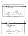
- the Figures 1 and 2 schematically illustrate first and second embodiments of the invention.
- the electronic system of Figures 1 and 2 comprises a discharge circuit 20 and a charging circuit 30 which are in parallel, i.e. the battery can be permanently charged from the main power supply and can immediately supply electrical energy when it is applied for discharge by the application.
- the electronic system of the invention also includes a continuity element of the discharge consisting of a diode D2 or D3 and which can be arranged in the charging circuit ( figure 1 ) or in the discharge circuit ( figure 2 ).
- the discharge circuit 20 comprises a power line for the circulation of an electric current from the battery to the application and a switch K2 disposed on this power line.
- the switch K2 is held in the open position as long as the battery is not discharged by the application and is operated in the closed position when electric power is required by the application.
- the term "open position" of the switch a position prohibiting any passage of current and "closed position" of the switch a position allowing a passage of current.
- the discharge circuit 20 may further comprise a diode D2 which is arranged in parallel with the switch K2 ( figure 2 ). This diode D2 prevents the flow of any charging current from the application to the battery and ensures the continuity of power availability during the transition phase before closing the switch K2.
- the charging circuit 30 comprises a charger and may comprise a diode D3 in antiparallel.
- the charging circuit 30 is a bidirectional branch, that is to say it allows the circulation of an electric current of the application to the battery for charging but also the circulation of an electric current of the battery to the application to ensure a discharge during a transition phase.
- the diode D2 of the discharge circuit 20 is then no longer necessary.
- the transition discharge by the charging circuit is provided by the diode D3; but this diode can be replaced by a suitable circuit integrated in the charger.
- the charger can integrate a simple K3C switch actuated in the closed position to allow the circulation of a charging current and actuated in the open position when the load must be interrupted; the diode D3 then ensures the circulation of a discharge current during the transition phase, that is to say the time for the switch K2 to go into the closed position.
- the charger can integrate a more complex circuit allowing bidirectional circulation of the current according to the command applied.
- the current limitation during discharge can be provided by a K3S switch. This switch also ensures redundancy of the K3C switch in the event of a charger failure during the charging phase of the battery. This K3S switch is optional and depends on the desired security level.
- the discharge circuit 30 does not allow the passage of strong currents, for example currents greater than 80A, which are necessary when the main supply fails.
- the discharge switch K3S is not dimensioned for strong currents and the passage through the diode D3 introduces an impedance which limits the current available for the application.
- the discharge through the charging circuit 30 is therefore transient and only makes it possible to guarantee immediate power availability while waiting for the discharge switch K2 to be actuated in the closed position.
- the transition discharge is provided by the diode D2 which ensures the circulation of a discharge current during the transition phase, that is to say the time for the switch K2 to go into the closed position.
- the charging circuit 30 is no longer a bidirectional branch, that is to say it only allows the flow of an electric current from the application to the battery for the load.
- the electronic system also comprises an electronic control unit which supervises the operation of the battery in order to regulate the charge of the accumulators and to allow the discharge of the battery when the application requires it.
- a control unit receives information from the application itself (potential of the main power supply, temperature, alarm for switching to emergency mode and others), sensors arranged in the battery (for example voltage, current and temperature). each accumulator) and status information (open position or closed position) of the different switches of the electronic system.
- the electronic control unit can thus maintain the charge of the battery without risk of overcharging; it can also detect a need for electrical energy of the application and control the stopping of the charger and the actuation of the switch K2 of the discharge circuit.
- the charging circuit charger 30 is connected to the main power supply network of the application.
- the charger is connected to the 28V network of the aircraft to ensure a maintenance of the battery charge to about 100% of its capacity.
- the charger limits the charging current to avoid any deposit of lithium on the electrodes.
- the electronic unit controls not only the K3C charger switch but also the K3S charge switch if present and provides control of the charging voltage at approximately 4V per electrochemical cell of the battery.
- the electronic unit receives a signal as to the status (open position or closed position) of the various switches K3S_statut, K3C_statut and K2_statut.
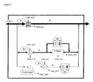
- FIG 3 schematically illustrates a third embodiment of the invention.
- the elements identical to the first embodiment carry the same reference numbers and are not described again.
- the figure 3 shows a second discharge circuit 40 of the battery parallel to the first discharge circuit 20.
- This second discharge circuit 40 comprises a second discharge switch K4 which is held in the closed position and a resistor R which limits the flow of current through this second discharge circuit.
- a diode D4 prohibits charging the battery through this second discharge switch K4.
- This second discharge circuit 40 makes it possible to use the battery under low currents, in particular when the electronics of the main charging and discharging branches 20 are put to sleep in "stand-by" mode, that is to say with the K2, K3C and K3S switches in open positions.
- the second discharge circuit 40 can be used to power pilot lights during the maintenance of the device without waking up all the electronics Battery control that consumes more electrical energy than the needs required by the application.
- Resistor R associated with a "current trigger” current trigger, makes it possible to limit the passage of a discharge current in this branch 40 to about 5A. Such a current is therefore insignificant when the battery is discharged via its main branch 20 but sufficient for maintenance and ground maintenance applications. Such a current also represents a negligible leak when the battery is charged by the charging circuit 30. If a stronger current call is required by the application, the electronic control unit of the system wakes the other branches and actuates the switch K2 discharge in closed position.
- the second discharge switch K4 always remains in the closed position; the electronic control unit does not have to operate in the closed position and this discharge branch 40 can be used when the electronic system is in "standby" mode.
- the second discharge switch K4 will be operated in the open position if a state of charge (SOC: State of Charge) of less than 20% is detected to suppress any leakage current.
- SOC State of Charge
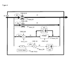
- FIG 4 schematically illustrates a fourth embodiment of the invention.
- the elements identical to the first and second embodiments have the same reference numbers and are not described again.
- the figure 4 shows a third discharge circuit 10 of the battery parallel to the first discharge circuit 20.
- This third discharge circuit 10 comprises a third discharge switch K1 which is held in the open position and actuated in the closed position when the application is requesting the battery for a start-up phase.
- the figure 4 shows the third discharge circuit 10 added to the second discharge circuit 40 illustrated on FIG. figure 3 , but it is understood that this third discharge circuit 10 could be added to the systems illustrated on the Figures 1 or 2 without the second discharge circuit 40 being provided.
- This third discharge circuit 10 makes it possible to preserve the reliability of the switches, in particular the discharge switch K2 of the first discharge circuit 20, which will be used in a backup mode of the battery.
- the third switch K1 may have the same technical specifications as the switch K2 of the first discharge circuit 20, or have greater robustness characteristics.
- the third switch K1 allows a current flow of more than 1500A and the switch K2 of the main discharge circuit 20 can be preserved from a passage of such strong currents.
- FIG 5 schematically illustrates a fifth embodiment of the invention.
- the elements identical to the three embodiments described above bear the same reference numbers and are not described again.
- a safety switch K2 has been added in series with the charging circuit 30 and in series with the first discharge circuit 20.
- the figure 5 shows the four branches of the system of the figure 4 except that the transition discharge is provided by the diode D2 of the discharge circuit 20 instead of being provided by the diode D3 of the charging circuit 30. It is however understood that the transition discharge could be provided by the diode D3 of the charging circuit 30 as on the figure 4 . It is understood that this security switch K2 'could also be added to the systems illustrated on one of the Figures 1 to 3 .
- the safety switch K2 ' is in series with the third discharge circuit 10 of strong currents but it is in parallel with the second discharge circuit 40 of weak currents.
- the safety switch K2 ' is kept in the closed position and actuated in the open position if a fault in the battery is detected and puts the user in a dangerous situation. It constitutes a redundancy of the switches K1, K2, K3C and K3S.
- the safety switch K2 ' In "stand by" mode, the safety switch K2 'is also in the open position. This is why the second weak current discharge circuit 40 must be parallel to this safety switch K2 '.
- the presence of the safety switch K2 ' also makes it possible to ensure the transition discharge either by the diode D2 of the discharge circuit 20 or by the diode D3 of the charging circuit 30. In fact, without the presence of this safety switch K2 ', the presence of a diode D2 parallel to the discharge switch K2 would guarantee a current of discharge in stand-by mode and eliminate the need for a second discharge branch 40.
- the discharge switch K3S has been removed from the discharge circuit 30.
- the switch K3S since the transition discharge is provided by the diode D2 of the charging circuit 20, the switch K3S is no longer necessary to ensure a limitation of the current. discharging through the charging circuit 30.
- the redundancy of the K3C switch in case of failure of the charger during the charging phase of the battery can be provided by the security switch K2 '.
- the K3S discharge switch could nevertheless be kept at the desired level of security.
- the electronic system according to the invention operates as follows.
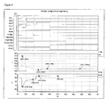
- the graphs of the figure 6 illustrate a simulation of the electronic system according to the invention in a start-up phase of the application then recharge the battery and put in "stand-by" mode.
- the simulation of the figure 6 was made with an electronic system as illustrated on the figure 4 .
- the first graph shows the state of the switches: the state "0" corresponds to an open position of the switch and the state "1" corresponds to a closed position of the switch.
- the second discharge switch K4 and the security switch K2 ' are not shown because their state remains the same except in extreme cases of low state of charge or failure of the other switches, as explained above.
- the second graph shows the current supplied by the battery and the third graph shows the voltage across the battery.
- the battery is initially charged to full capacity; it has a voltage substantially equal to that of the 28V network of the main supply of the application and it does not supply or receive any current.
- the charger is interrupted (K3C switch in the open position) and the discharge switch K2 is in the open position.
- the charging switch K3S is in the closed position; in case of a current call from the application, even before one of the discharge switches K1 or K2 is actuated, a discharge will be possible through the diode D3 of the charging circuit 30.
- the charge of the battery remains however impossible until the K3C charger switch is turned on. Immediate power availability is ensured.
- the electronic control unit will control the closing of the third discharge switch K1 to allow the circulation of a high amplitude current and the opening of the load switch K3S to avoid any return of current to the battery.
- the first discharge circuit 20 takes over the third discharge circuit 10 to supply the electrical energy to the application; the first discharge switch K2 is actuated in the closed position and the third discharge switch K1 is actuated in the open position.
- the discharge can be conducted at very high powers relative to the load, without interruption of power when the battery is requested.
- the dissymmetry of the available currents in charge compared to the discharge is due to the Li-ion electrochemistry and the possibility of depositing lithium during too fast charges, which would considerably reduce its performances and its lifetime.
- the battery can be recharged.
- the discharge switch K2 is returned to the open position, the charging switch K3S is actuated in the closed position.
- the K3C charger switch will be activated if the grid voltage is higher than the battery voltage.
- the charge of the battery then becomes possible from the main power supply network.
- the load is regulated by closing and opening the charger switch K3C while the charging switch K3S remains in the closed position.
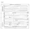
- the graphs of the figure 7 illustrate a simulation of the electronic system according to the invention in an emergency mode of the application.
- the simulation of the figure 6 was made with an electronic system as illustrated on the figure 4 .
- the first graph shows the state of the switches
- the second graph shows the current supplied through the transition diode
- the third graph shows the current through the load branch
- the fourth graph shows the current through the discharge branch
- the last graph shows the voltage across the battery.
- the battery is initially charged with an 80% SOC; the charger holds the load (switch K3C in the closed position), the charging switch K3S is in the closed position and the discharge switch K2 is in position opened.
- the Electronic control unit will control the closing of the K2C discharge switch and the opening of the K3C charger switch to stop charging.
- the electronic control unit detects an emergency mode, it keeps the K3S charge switch in the open position and it inhibits all the safety of the battery so as not to slow down the power supply of the backup battery.
- the potential of the application may become greater than the potential of the battery while the emergency mode is still active, for example because the battery reaches a relatively low charge state compared to the main supply voltage.
- the battery could then go into a charging phase with a flow of current from the application to the battery through the power line of the discharge circuit 20.
- the electronic control unit if it detects a potential of the battery lower than that of the application network while a backup mode is active, will operate the opening of the discharge switch K2 in order to prevent charging of the battery from the application whose main power supply has failed. As soon as the discharge becomes possible, even before the discharge switch K2 is closed again, the electric power of the battery is again available through the diode of the charging circuit D3. Any discontinuity of power availability is thus avoided.
- the electronic unit controls the opening of all the switches of the battery, including the second discharge switch K4 to prohibit the over-discharge of the batteries. battery cells.
- the backup battery according to the invention can thus be maintained in a state of charge close to 100% permanently from the main power supply.
- the application as long as it is not requested in its backup function or for a start of the APU.
- a particular application of such a backup battery can be envisaged for aircraft and especially for large drones that requires a large capacity; the backup battery can be charged by the main power of the aircraft as long as it is operational and can deliver electrical energy to the aircraft as soon as necessary without power discontinuity.
Landscapes
- Engineering & Computer Science (AREA)
- Power Engineering (AREA)
- Business, Economics & Management (AREA)
- Emergency Management (AREA)
- Charge And Discharge Circuits For Batteries Or The Like (AREA)
- Secondary Cells (AREA)
- Control Of Electrical Variables (AREA)
Applications Claiming Priority (1)
| Application Number | Priority Date | Filing Date | Title |
|---|---|---|---|
| FR0800464A FR2926934B1 (fr) | 2008-01-29 | 2008-01-29 | Systeme electronique pour batterie |
Publications (3)
| Publication Number | Publication Date |
|---|---|
| EP2085268A2 true EP2085268A2 (de) | 2009-08-05 |
| EP2085268A3 EP2085268A3 (de) | 2010-09-08 |
| EP2085268B1 EP2085268B1 (de) | 2019-08-14 |
Family
ID=39618991
Family Applications (1)
| Application Number | Title | Priority Date | Filing Date |
|---|---|---|---|
| EP09290026.5A Active EP2085268B1 (de) | 2008-01-29 | 2009-01-13 | Elektronisches System für Batterie |
Country Status (4)
| Country | Link |
|---|---|
| US (1) | US8193773B2 (de) |
| EP (1) | EP2085268B1 (de) |
| JP (1) | JP2009183139A (de) |
| FR (1) | FR2926934B1 (de) |
Cited By (3)
| Publication number | Priority date | Publication date | Assignee | Title |
|---|---|---|---|---|
| FR3038787A1 (fr) * | 2015-07-06 | 2017-01-13 | Snecma | Procede d'alimentation et de commande d'un actionneur electrique, module de commande correspondant, actionneur et turbomachine le comprenant |
| CN108268079A (zh) * | 2018-01-25 | 2018-07-10 | 南京佰联信息技术有限公司 | 地面电源输出电压调整方法及系统和计算机可读存储介质 |
| FR3082068A1 (fr) * | 2018-05-30 | 2019-12-06 | Blue Solutions | Dispositif et systeme rechargeables de stockage d'energie electrique, vehicule et installation munis d'un tel systeme |
Families Citing this family (14)
| Publication number | Priority date | Publication date | Assignee | Title |
|---|---|---|---|---|
| US8179092B2 (en) | 2010-04-12 | 2012-05-15 | Concorde Battery Corporation | Lithium-ion aircraft battery with automatically activated battery management system |
| DE102011081906A1 (de) * | 2011-08-31 | 2013-02-28 | Bayerische Motoren Werke Aktiengesellschaft | Elektrochemisches Energiespeichersystem |
| US9515521B2 (en) * | 2011-11-15 | 2016-12-06 | Isaberg Rapid Ab | Detector arrangement in an electric arrangement with stand by shut down |
| US9041344B2 (en) | 2012-05-25 | 2015-05-26 | Timotion Technology Co., Ltd. | Standby battery box for electric cylinder |
| DK177581B1 (en) * | 2012-05-31 | 2013-10-28 | Timotion Technology Co Ltd | Standby battery box for electric cylinder |
| TWI477017B (zh) * | 2012-07-24 | 2015-03-11 | 光寶科技股份有限公司 | 避免電池浮充之控制系統、供電系統及方法 |
| JP6260106B2 (ja) * | 2013-04-25 | 2018-01-17 | 株式会社Gsユアサ | 蓄電装置 |
| JP6412757B2 (ja) * | 2014-09-30 | 2018-10-24 | Fdk株式会社 | 電源装置 |
| JP6665551B2 (ja) | 2016-01-22 | 2020-03-13 | 株式会社Gsユアサ | バッテリ装置および二次電池の不正使用判断方法 |
| CN109659993A (zh) * | 2018-12-10 | 2019-04-19 | 深圳供电局有限公司 | 续流装置及无人机供电系统 |
| US12286017B2 (en) | 2021-10-30 | 2025-04-29 | Beta Air Llc | System and methods for an immediate shutdown of charging for an electric aircraft |
| US11735932B2 (en) | 2021-10-30 | 2023-08-22 | Beta Air, Llc | System and methods for an immediate shutdown of an electric vehicle charger |
| US11705743B2 (en) | 2021-10-30 | 2023-07-18 | Beta Air, Llc | Systems and methods for emergency shutdown of an electric charger in response to a disconnection |
| KR20240095698A (ko) | 2022-12-16 | 2024-06-26 | 현대자동차주식회사 | 프리차징 회로를 이용한 병렬형 배터리팩 밸런싱 방법 및 그를 위한 장치 및 시스템 |
Citations (1)
| Publication number | Priority date | Publication date | Assignee | Title |
|---|---|---|---|---|
| JP2000224769A (ja) | 1999-01-28 | 2000-08-11 | Shikoku Electric Power Co Inc | 分散型蓄電システム |
Family Cites Families (21)
| Publication number | Priority date | Publication date | Assignee | Title |
|---|---|---|---|---|
| US4163934A (en) * | 1977-07-06 | 1979-08-07 | Francis Lawn | Methods and apparatus for charging batteries |
| JP3154503B2 (ja) * | 1991-04-16 | 2001-04-09 | 三菱電機株式会社 | 内燃機関制御装置 |
| US5293076A (en) * | 1991-04-16 | 1994-03-08 | Mitsubishi Denki Kabushiki Kaisha | Vehicle control apparatus |
| JPH04318238A (ja) * | 1991-04-17 | 1992-11-09 | Mitsubishi Electric Corp | 内燃機関制御装置 |
| JPH04318239A (ja) * | 1991-04-18 | 1992-11-09 | Mitsubishi Electric Corp | 内燃機関制御装置 |
| JPH06113469A (ja) * | 1992-09-25 | 1994-04-22 | Yuasa Corp | 鉄道車両用密閉形蓄電池の充電システム |
| JP2708374B2 (ja) * | 1994-07-26 | 1998-02-04 | インターナショナル・ビジネス・マシーンズ・コーポレイション | コンピュータ用バッテリ接続装置及びバッテリの切換方法 |
| JP3228102B2 (ja) * | 1995-11-29 | 2001-11-12 | 三菱電機株式会社 | 太陽電池電源装置 |
| JPH10201129A (ja) * | 1996-12-27 | 1998-07-31 | Japan Storage Battery Co Ltd | 太陽光エネルギ−活用発電設備 |
| CA2258340A1 (en) * | 1997-01-31 | 1998-08-06 | Ira S. Faberman | Uninterruptible power supply |
| US5909103A (en) * | 1997-07-24 | 1999-06-01 | Siliconix Incorporated | Safety switch for lithium ion battery |
| US6074775A (en) * | 1998-04-02 | 2000-06-13 | The Procter & Gamble Company | Battery having a built-in controller |
| US6075343A (en) * | 1999-02-12 | 2000-06-13 | Quanta Computer Inc. | Rechargeable battery pack module |
| JP4572018B2 (ja) * | 2000-04-27 | 2010-10-27 | 富士通株式会社 | 電池パックおよび電子機器システム |
| US20050007071A1 (en) * | 2003-05-23 | 2005-01-13 | Jens Colberg | Circuit arrangement for an autonomous power supply system, and a method for its operation |
| US7786619B2 (en) * | 2003-09-12 | 2010-08-31 | The Chamberlain Group, Inc. | DC power backup |
| JP2005160251A (ja) * | 2003-11-27 | 2005-06-16 | Ntt Power & Building Facilities Inc | 電力供給システム |
| JP4367374B2 (ja) * | 2005-05-16 | 2009-11-18 | パナソニック株式会社 | 蓄電装置 |
| US20070273216A1 (en) * | 2006-05-24 | 2007-11-29 | Farbarik John M | Systems and Methods for Reducing Power Losses in a Medical Device |
| FR2925789A1 (fr) * | 2007-12-20 | 2009-06-26 | Commissariat Energie Atomique | Convertisseur electrique a capacite variable |
| JPWO2011074196A1 (ja) * | 2009-12-16 | 2013-04-25 | パナソニック株式会社 | 電池パック、放電システム、充放電システム及びリチウムイオン二次電池の放電制御方法 |
-
2008
- 2008-01-29 FR FR0800464A patent/FR2926934B1/fr active Active
-
2009
- 2009-01-13 EP EP09290026.5A patent/EP2085268B1/de active Active
- 2009-01-23 US US12/359,057 patent/US8193773B2/en not_active Expired - Fee Related
- 2009-01-28 JP JP2009016902A patent/JP2009183139A/ja active Pending
Patent Citations (1)
| Publication number | Priority date | Publication date | Assignee | Title |
|---|---|---|---|---|
| JP2000224769A (ja) | 1999-01-28 | 2000-08-11 | Shikoku Electric Power Co Inc | 分散型蓄電システム |
Cited By (3)
| Publication number | Priority date | Publication date | Assignee | Title |
|---|---|---|---|---|
| FR3038787A1 (fr) * | 2015-07-06 | 2017-01-13 | Snecma | Procede d'alimentation et de commande d'un actionneur electrique, module de commande correspondant, actionneur et turbomachine le comprenant |
| CN108268079A (zh) * | 2018-01-25 | 2018-07-10 | 南京佰联信息技术有限公司 | 地面电源输出电压调整方法及系统和计算机可读存储介质 |
| FR3082068A1 (fr) * | 2018-05-30 | 2019-12-06 | Blue Solutions | Dispositif et systeme rechargeables de stockage d'energie electrique, vehicule et installation munis d'un tel systeme |
Also Published As
| Publication number | Publication date |
|---|---|
| EP2085268A3 (de) | 2010-09-08 |
| US20090189568A1 (en) | 2009-07-30 |
| EP2085268B1 (de) | 2019-08-14 |
| US8193773B2 (en) | 2012-06-05 |
| FR2926934A1 (fr) | 2009-07-31 |
| FR2926934B1 (fr) | 2010-09-17 |
| JP2009183139A (ja) | 2009-08-13 |
Similar Documents
| Publication | Publication Date | Title |
|---|---|---|
| EP2085268B1 (de) | Elektronisches System für Batterie | |
| EP2452384B1 (de) | Verlustarmer akkumulator | |
| EP1265336B1 (de) | Ausgleichverfahren für eine elektrische Batterie im diskontinuierlichen Lade-Modus und Batterieverwaltungssystem zur Durchführung des Verfahrens | |
| EP1202426B1 (de) | Universelles Batterieladegerät und Verfahren | |
| EP2684274A1 (de) | Ladungsausgleichssysteme für batterien | |
| EP2416468A2 (de) | Batterieausgleichsverfahren und Steuerungssystem dafür | |
| EP2079125B1 (de) | Verfahren zur Steuerung des Aufladevorgangs einer Batterie | |
| FR2982998A1 (fr) | Batterie d'accumulateurs protegee contre les courts-circuits internes | |
| EP2600462A1 (de) | Verfahren zum Ausgleich von Spannungen elektrischer Elemente, die auf mehreren parallelen Zweigen angeordnet sind | |
| WO2016083690A1 (fr) | Pack de batteries pour un vehicule automobile | |
| EP3864735A1 (de) | Verfahren und vorrichtung zur regelung des ladezustandes einer traktionsbatterie eines elektrofahrzeuges | |
| EP2363939B1 (de) | Unterbrechungsfreie Wechselstromversorgung einer Installation und Verfahren dazu | |
| FR2908939A1 (fr) | Dispositif de commande pour assurer la regulation en tension d'un bus d'alimentation. | |
| EP3472911B1 (de) | Verfahren und system zur verwaltung von elektrochemischen batterien einer stromversorgungsanlage im fall eines batterieausfalls | |
| FR2916578A1 (fr) | Systeme electronique pour batterie. | |
| EP0077531A1 (de) | Ladeeinrichtung für eine Batteriegruppe, insbesondere für Pufferbatterien die durch eine leistungsbegrenzte Stromversorgungsanordnung gespeist werden | |
| FR2810809A1 (fr) | Dispositif d'alimentation pour appareils electriques portables | |
| EP1829152B1 (de) | Verfahren zur aufrechterhaltung des geladenen zustandes eines blei-akkumulator | |
| FR3114453A1 (fr) | Dispositif d’alimentation | |
| FR2849298A1 (fr) | Dispositif de controle de l'etat de charge, a tension constante, d'un ensemble de batterie a generateurs electrochimiques secondaires | |
| EP4645642A1 (de) | Verfahren und vorrichtung zur steuerung einer batterie von elektrochemischen akkumulatoren | |
| FR2959631A1 (fr) | Systeme de deconnexion pour batterie | |
| FR2977403A1 (fr) | Circuit de deconnexion pour batterie | |
| FR3022400A1 (fr) | Protection d'une batterie contre une absence de charge prolongee | |
| FR3094680A1 (fr) | Vehicule automobile comprenant un circuit d’alimentation electrique a double accumulateur au lithium |
Legal Events
| Date | Code | Title | Description |
|---|---|---|---|
| PUAI | Public reference made under article 153(3) epc to a published international application that has entered the european phase |
Free format text: ORIGINAL CODE: 0009012 |
|
| AK | Designated contracting states |
Kind code of ref document: A2 Designated state(s): AT BE BG CH CY CZ DE DK EE ES FI FR GB GR HR HU IE IS IT LI LT LU LV MC MK MT NL NO PL PT RO SE SI SK TR |
|
| AX | Request for extension of the european patent |
Extension state: AL BA RS |
|
| PUAL | Search report despatched |
Free format text: ORIGINAL CODE: 0009013 |
|
| AK | Designated contracting states |
Kind code of ref document: A3 Designated state(s): AT BE BG CH CY CZ DE DK EE ES FI FR GB GR HR HU IE IS IT LI LT LU LV MC MK MT NL NO PL PT RO SE SI SK TR |
|
| AX | Request for extension of the european patent |
Extension state: AL BA RS |
|
| RIC1 | Information provided on ipc code assigned before grant |
Ipc: H02J 9/06 20060101ALI20100804BHEP Ipc: B60R 16/03 20060101ALI20100804BHEP Ipc: H02J 7/00 20060101AFI20100804BHEP |
|
| 17P | Request for examination filed |
Effective date: 20110308 |
|
| AKX | Designation fees paid |
Designated state(s): DE FR GB |
|
| 17Q | First examination report despatched |
Effective date: 20151015 |
|
| GRAP | Despatch of communication of intention to grant a patent |
Free format text: ORIGINAL CODE: EPIDOSNIGR1 |
|
| INTG | Intention to grant announced |
Effective date: 20190516 |
|
| GRAS | Grant fee paid |
Free format text: ORIGINAL CODE: EPIDOSNIGR3 |
|
| GRAA | (expected) grant |
Free format text: ORIGINAL CODE: 0009210 |
|
| AK | Designated contracting states |
Kind code of ref document: B1 Designated state(s): DE FR GB |
|
| REG | Reference to a national code |
Ref country code: GB Ref legal event code: FG4D Free format text: NOT ENGLISH |
|
| REG | Reference to a national code |
Ref country code: DE Ref legal event code: R096 Ref document number: 602009059441 Country of ref document: DE |
|
| REG | Reference to a national code |
Ref country code: DE Ref legal event code: R097 Ref document number: 602009059441 Country of ref document: DE |
|
| PLBE | No opposition filed within time limit |
Free format text: ORIGINAL CODE: 0009261 |
|
| STAA | Information on the status of an ep patent application or granted ep patent |
Free format text: STATUS: NO OPPOSITION FILED WITHIN TIME LIMIT |
|
| 26N | No opposition filed |
Effective date: 20200603 |
|
| PGFP | Annual fee paid to national office [announced via postgrant information from national office to epo] |
Ref country code: FR Payment date: 20210114 Year of fee payment: 13 |
|
| PG25 | Lapsed in a contracting state [announced via postgrant information from national office to epo] |
Ref country code: FR Free format text: LAPSE BECAUSE OF NON-PAYMENT OF DUE FEES Effective date: 20220131 |
|
| PGFP | Annual fee paid to national office [announced via postgrant information from national office to epo] |
Ref country code: GB Payment date: 20230131 Year of fee payment: 15 |
|
| GBPC | Gb: european patent ceased through non-payment of renewal fee |
Effective date: 20240113 |
|
| PG25 | Lapsed in a contracting state [announced via postgrant information from national office to epo] |
Ref country code: GB Free format text: LAPSE BECAUSE OF NON-PAYMENT OF DUE FEES Effective date: 20240113 |
|
| PG25 | Lapsed in a contracting state [announced via postgrant information from national office to epo] |
Ref country code: GB Free format text: LAPSE BECAUSE OF NON-PAYMENT OF DUE FEES Effective date: 20240113 |
|
| PGFP | Annual fee paid to national office [announced via postgrant information from national office to epo] |
Ref country code: DE Payment date: 20250130 Year of fee payment: 17 |