EP2085268A2 - Electronic system for battery - Google Patents
Electronic system for battery Download PDFInfo
- Publication number
- EP2085268A2 EP2085268A2 EP09290026A EP09290026A EP2085268A2 EP 2085268 A2 EP2085268 A2 EP 2085268A2 EP 09290026 A EP09290026 A EP 09290026A EP 09290026 A EP09290026 A EP 09290026A EP 2085268 A2 EP2085268 A2 EP 2085268A2
- Authority
- EP
- European Patent Office
- Prior art keywords
- discharge
- battery
- switch
- circuit
- electronic system
- Prior art date
- Legal status (The legal status is an assumption and is not a legal conclusion. Google has not performed a legal analysis and makes no representation as to the accuracy of the status listed.)
- Granted
Links
- 238000007599 discharging Methods 0.000 claims abstract description 8
- 230000007704 transition Effects 0.000 claims description 14
- 229910001416 lithium ion Inorganic materials 0.000 claims description 10
- 230000002457 bidirectional effect Effects 0.000 claims description 5
- HBBGRARXTFLTSG-UHFFFAOYSA-N Lithium ion Chemical compound [Li+] HBBGRARXTFLTSG-UHFFFAOYSA-N 0.000 claims description 2
- 238000004088 simulation Methods 0.000 description 7
- 238000012423 maintenance Methods 0.000 description 5
- WHXSMMKQMYFTQS-UHFFFAOYSA-N Lithium Chemical compound [Li] WHXSMMKQMYFTQS-UHFFFAOYSA-N 0.000 description 2
- 230000008901 benefit Effects 0.000 description 2
- 229910052744 lithium Inorganic materials 0.000 description 2
- 239000000126 substance Substances 0.000 description 2
- 230000001052 transient effect Effects 0.000 description 2
- 101100536354 Drosophila melanogaster tant gene Proteins 0.000 description 1
- 206010063493 Premature ageing Diseases 0.000 description 1
- 208000032038 Premature aging Diseases 0.000 description 1
- 239000002253 acid Substances 0.000 description 1
- 230000032683 aging Effects 0.000 description 1
- OJIJEKBXJYRIBZ-UHFFFAOYSA-N cadmium nickel Chemical compound [Ni].[Cd] OJIJEKBXJYRIBZ-UHFFFAOYSA-N 0.000 description 1
- 150000001875 compounds Chemical class 0.000 description 1
- 230000007423 decrease Effects 0.000 description 1
- 230000002950 deficient Effects 0.000 description 1
- 238000000151 deposition Methods 0.000 description 1
- 230000005611 electricity Effects 0.000 description 1
- 238000003487 electrochemical reaction Methods 0.000 description 1
- 230000005518 electrochemistry Effects 0.000 description 1
- 230000001105 regulatory effect Effects 0.000 description 1
- 230000002618 waking effect Effects 0.000 description 1
Images

Classifications
-
- H—ELECTRICITY
- H02—GENERATION; CONVERSION OR DISTRIBUTION OF ELECTRIC POWER
- H02J—CIRCUIT ARRANGEMENTS OR SYSTEMS FOR SUPPLYING OR DISTRIBUTING ELECTRIC POWER; SYSTEMS FOR STORING ELECTRIC ENERGY
- H02J9/00—Circuit arrangements for emergency or stand-by power supply, e.g. for emergency lighting
- H02J9/04—Circuit arrangements for emergency or stand-by power supply, e.g. for emergency lighting in which the distribution system is disconnected from the normal source and connected to a standby source
- H02J9/06—Circuit arrangements for emergency or stand-by power supply, e.g. for emergency lighting in which the distribution system is disconnected from the normal source and connected to a standby source with automatic change-over, e.g. UPS systems
- H02J9/061—Circuit arrangements for emergency or stand-by power supply, e.g. for emergency lighting in which the distribution system is disconnected from the normal source and connected to a standby source with automatic change-over, e.g. UPS systems for DC powered loads
-
- H—ELECTRICITY
- H02—GENERATION; CONVERSION OR DISTRIBUTION OF ELECTRIC POWER
- H02J—CIRCUIT ARRANGEMENTS OR SYSTEMS FOR SUPPLYING OR DISTRIBUTING ELECTRIC POWER; SYSTEMS FOR STORING ELECTRIC ENERGY
- H02J7/00—Circuit arrangements for charging or depolarising batteries or for supplying loads from batteries
- H02J7/0068—Battery or charger load switching, e.g. concurrent charging and load supply
Definitions
- the present invention relates to an electronic system for battery comprising at least one sealed accumulator.
- An electrochemical generator or accumulator (these two terms are equivalent) is a device for generating electricity in which chemical energy is converted into electrical energy.
- the chemical energy consists of electrochemically active compounds deposited on at least one electrode face disposed in the accumulator.
- the electrical energy is produced by electrochemical reactions during a discharge of the accumulator.
- the electrodes, disposed in a container, are electrically connected to current output terminals which provide electrical continuity between the electrodes and an electrical consumer with which the accumulator is associated.
- the battery is intended to supply electrical power to an outdoor application; a charging circuit is therefore generally provided to which the battery can be connected to recharge the batteries.
- a charging circuit is therefore generally provided to which the battery can be connected to recharge the batteries.
- it is known to associate several sealed accumulators together to form a battery.
- the battery then has one or more parallel branches of accumulators connected in series.
- the management of the charging and discharging of the battery can then be organized and controlled to balance the charging and discharging of the different accumulators relative to each other.
- a control circuit more or less evolved according to the applications, is generally intended to be associated with the battery.
- Aircraft or other transport vehicles typically use lead-acid batteries or Nickel Cadmium (NiCd) batteries to start the vehicle and provide emergency power. These batteries can remain connected to the main power supply and be charged as long as they are not used; no overcharging of the accumulators is to be feared.
- Li-Ion type batteries as backup battery, especially for aircraft applications in order to benefit from a reduction in weight and ease of maintenance specific to this type of aircraft. drums.
- Li-Ion batteries require specific charge management to avoid overcharging. It has indeed been observed that the overcharging of Li-Ion accumulators causes premature aging of the battery. It is therefore not possible to directly replace a NiCd or lead battery with a Li-Ion battery; a system Battery management electronics should be provided to control the charging and balancing of Li-Ion batteries.
- a backup battery can deliver electrical power to the application for which it is intended quickly, reliably and without discontinuity when the main power supply of the application is defective.
- the invention proposes an electronic system for a battery, in particular for a backup battery, which makes it possible to control the charge of the accumulators in order to maintain an optimal state of charge without overloading and which makes it possible to ensure a reliable discharge without interruption of power when the battery is in use.
- the continuity element of the discharge is disposed in the load circuit which is a bidirectional branch.
- the charging circuit may comprise a charging switch arranged in series with the charger and a diode arranged in parallel with the charger, the diode allowing the discharge of the battery when the charge switch is in the closed position and the charger interrupted.
- the continuity element of the discharge is a discharge diode disposed in the parallel discharge circuit of the discharge switch.
- the charging circuit does not allow a current flow greater than 80A.
- control unit actuates the discharge switch in the open position when the potential of the battery becomes lower than the potential of the application.
- the system further comprises a second discharge circuit of the battery parallel to the first discharge circuit and comprising a second discharge switch held in closed position, a resistor limiting the passage of the discharge current and a diode prohibiting charging the battery through the second discharge switch.
- the resistance of the second discharge circuit can limit the discharge current to 5A; and the second discharge switch can be held in the closed position as long as the state of charge of the battery is greater than 20%.
- the system further comprises a third discharge circuit of the battery parallel to the first discharge circuit and comprising a third discharge switch actuated in the closed position when a start phase of the application is detected.
- the third discharge switch can allow a current flow greater than 1500A
- the system further comprises a safety switch arranged in series with the charging circuit and in series with the first discharge circuit and actuated in the open position when a dangerous situation for the user of the battery is detected.
- the safety switch is arranged in parallel with the second discharge circuit.
- the invention also relates to a rechargeable battery comprising at least one sealed electrochemical accumulator and an electronic system according to the invention.
- the sealed accumulator may be of the Lithium-Ion type.
- Such a battery can be used for an aircraft for example.
- the invention relates to an electronic system for a battery comprising at least one rechargeable electrochemical accumulator.
- the battery is permanently connected to a power bus of a main power supply of the application for which it is intended.
- the electronic system of the invention controls the charge of the accumulators in order to avoid any overload and guarantees the continuity of the availability of electrical power when the battery is requested for discharge.
- the invention applies in particular to a backup battery, that is to say a battery for supplying electrical power to an external application in case of failure of the main power supply.
- the battery can also be requested for a start of an auxiliary power unit (APU for "Auxialiary Power Unit” in English) of the application.
- APU for "Auxialiary Power Unit” in English
- the application can be a vehicle, for example an airplane.
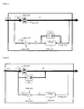
- the Figures 1 and 2 schematically illustrate first and second embodiments of the invention.
- the electronic system of Figures 1 and 2 comprises a discharge circuit 20 and a charging circuit 30 which are in parallel, i.e. the battery can be permanently charged from the main power supply and can immediately supply electrical energy when it is applied for discharge by the application.
- the electronic system of the invention also includes a continuity element of the discharge consisting of a diode D2 or D3 and which can be arranged in the charging circuit ( figure 1 ) or in the discharge circuit ( figure 2 ).
- the discharge circuit 20 comprises a power line for the circulation of an electric current from the battery to the application and a switch K2 disposed on this power line.
- the switch K2 is held in the open position as long as the battery is not discharged by the application and is operated in the closed position when electric power is required by the application.
- the term "open position" of the switch a position prohibiting any passage of current and "closed position" of the switch a position allowing a passage of current.
- the discharge circuit 20 may further comprise a diode D2 which is arranged in parallel with the switch K2 ( figure 2 ). This diode D2 prevents the flow of any charging current from the application to the battery and ensures the continuity of power availability during the transition phase before closing the switch K2.
- the charging circuit 30 comprises a charger and may comprise a diode D3 in antiparallel.
- the charging circuit 30 is a bidirectional branch, that is to say it allows the circulation of an electric current of the application to the battery for charging but also the circulation of an electric current of the battery to the application to ensure a discharge during a transition phase.
- the diode D2 of the discharge circuit 20 is then no longer necessary.
- the transition discharge by the charging circuit is provided by the diode D3; but this diode can be replaced by a suitable circuit integrated in the charger.
- the charger can integrate a simple K3C switch actuated in the closed position to allow the circulation of a charging current and actuated in the open position when the load must be interrupted; the diode D3 then ensures the circulation of a discharge current during the transition phase, that is to say the time for the switch K2 to go into the closed position.
- the charger can integrate a more complex circuit allowing bidirectional circulation of the current according to the command applied.
- the current limitation during discharge can be provided by a K3S switch. This switch also ensures redundancy of the K3C switch in the event of a charger failure during the charging phase of the battery. This K3S switch is optional and depends on the desired security level.
- the discharge circuit 30 does not allow the passage of strong currents, for example currents greater than 80A, which are necessary when the main supply fails.
- the discharge switch K3S is not dimensioned for strong currents and the passage through the diode D3 introduces an impedance which limits the current available for the application.
- the discharge through the charging circuit 30 is therefore transient and only makes it possible to guarantee immediate power availability while waiting for the discharge switch K2 to be actuated in the closed position.
- the transition discharge is provided by the diode D2 which ensures the circulation of a discharge current during the transition phase, that is to say the time for the switch K2 to go into the closed position.
- the charging circuit 30 is no longer a bidirectional branch, that is to say it only allows the flow of an electric current from the application to the battery for the load.
- the electronic system also comprises an electronic control unit which supervises the operation of the battery in order to regulate the charge of the accumulators and to allow the discharge of the battery when the application requires it.
- a control unit receives information from the application itself (potential of the main power supply, temperature, alarm for switching to emergency mode and others), sensors arranged in the battery (for example voltage, current and temperature). each accumulator) and status information (open position or closed position) of the different switches of the electronic system.
- the electronic control unit can thus maintain the charge of the battery without risk of overcharging; it can also detect a need for electrical energy of the application and control the stopping of the charger and the actuation of the switch K2 of the discharge circuit.
- the charging circuit charger 30 is connected to the main power supply network of the application.
- the charger is connected to the 28V network of the aircraft to ensure a maintenance of the battery charge to about 100% of its capacity.
- the charger limits the charging current to avoid any deposit of lithium on the electrodes.
- the electronic unit controls not only the K3C charger switch but also the K3S charge switch if present and provides control of the charging voltage at approximately 4V per electrochemical cell of the battery.
- the electronic unit receives a signal as to the status (open position or closed position) of the various switches K3S_statut, K3C_statut and K2_statut.
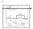
- FIG 3 schematically illustrates a third embodiment of the invention.
- the elements identical to the first embodiment carry the same reference numbers and are not described again.
- the figure 3 shows a second discharge circuit 40 of the battery parallel to the first discharge circuit 20.
- This second discharge circuit 40 comprises a second discharge switch K4 which is held in the closed position and a resistor R which limits the flow of current through this second discharge circuit.
- a diode D4 prohibits charging the battery through this second discharge switch K4.
- This second discharge circuit 40 makes it possible to use the battery under low currents, in particular when the electronics of the main charging and discharging branches 20 are put to sleep in "stand-by" mode, that is to say with the K2, K3C and K3S switches in open positions.
- the second discharge circuit 40 can be used to power pilot lights during the maintenance of the device without waking up all the electronics Battery control that consumes more electrical energy than the needs required by the application.
- Resistor R associated with a "current trigger” current trigger, makes it possible to limit the passage of a discharge current in this branch 40 to about 5A. Such a current is therefore insignificant when the battery is discharged via its main branch 20 but sufficient for maintenance and ground maintenance applications. Such a current also represents a negligible leak when the battery is charged by the charging circuit 30. If a stronger current call is required by the application, the electronic control unit of the system wakes the other branches and actuates the switch K2 discharge in closed position.
- the second discharge switch K4 always remains in the closed position; the electronic control unit does not have to operate in the closed position and this discharge branch 40 can be used when the electronic system is in "standby" mode.
- the second discharge switch K4 will be operated in the open position if a state of charge (SOC: State of Charge) of less than 20% is detected to suppress any leakage current.
- SOC State of Charge
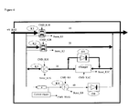
- FIG 4 schematically illustrates a fourth embodiment of the invention.
- the elements identical to the first and second embodiments have the same reference numbers and are not described again.
- the figure 4 shows a third discharge circuit 10 of the battery parallel to the first discharge circuit 20.
- This third discharge circuit 10 comprises a third discharge switch K1 which is held in the open position and actuated in the closed position when the application is requesting the battery for a start-up phase.
- the figure 4 shows the third discharge circuit 10 added to the second discharge circuit 40 illustrated on FIG. figure 3 , but it is understood that this third discharge circuit 10 could be added to the systems illustrated on the Figures 1 or 2 without the second discharge circuit 40 being provided.
- This third discharge circuit 10 makes it possible to preserve the reliability of the switches, in particular the discharge switch K2 of the first discharge circuit 20, which will be used in a backup mode of the battery.
- the third switch K1 may have the same technical specifications as the switch K2 of the first discharge circuit 20, or have greater robustness characteristics.
- the third switch K1 allows a current flow of more than 1500A and the switch K2 of the main discharge circuit 20 can be preserved from a passage of such strong currents.
- FIG 5 schematically illustrates a fifth embodiment of the invention.
- the elements identical to the three embodiments described above bear the same reference numbers and are not described again.
- a safety switch K2 has been added in series with the charging circuit 30 and in series with the first discharge circuit 20.
- the figure 5 shows the four branches of the system of the figure 4 except that the transition discharge is provided by the diode D2 of the discharge circuit 20 instead of being provided by the diode D3 of the charging circuit 30. It is however understood that the transition discharge could be provided by the diode D3 of the charging circuit 30 as on the figure 4 . It is understood that this security switch K2 'could also be added to the systems illustrated on one of the Figures 1 to 3 .
- the safety switch K2 ' is in series with the third discharge circuit 10 of strong currents but it is in parallel with the second discharge circuit 40 of weak currents.
- the safety switch K2 ' is kept in the closed position and actuated in the open position if a fault in the battery is detected and puts the user in a dangerous situation. It constitutes a redundancy of the switches K1, K2, K3C and K3S.
- the safety switch K2 ' In "stand by" mode, the safety switch K2 'is also in the open position. This is why the second weak current discharge circuit 40 must be parallel to this safety switch K2 '.
- the presence of the safety switch K2 ' also makes it possible to ensure the transition discharge either by the diode D2 of the discharge circuit 20 or by the diode D3 of the charging circuit 30. In fact, without the presence of this safety switch K2 ', the presence of a diode D2 parallel to the discharge switch K2 would guarantee a current of discharge in stand-by mode and eliminate the need for a second discharge branch 40.
- the discharge switch K3S has been removed from the discharge circuit 30.
- the switch K3S since the transition discharge is provided by the diode D2 of the charging circuit 20, the switch K3S is no longer necessary to ensure a limitation of the current. discharging through the charging circuit 30.
- the redundancy of the K3C switch in case of failure of the charger during the charging phase of the battery can be provided by the security switch K2 '.
- the K3S discharge switch could nevertheless be kept at the desired level of security.
- the electronic system according to the invention operates as follows.
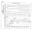
- the graphs of the figure 6 illustrate a simulation of the electronic system according to the invention in a start-up phase of the application then recharge the battery and put in "stand-by" mode.
- the simulation of the figure 6 was made with an electronic system as illustrated on the figure 4 .
- the first graph shows the state of the switches: the state "0" corresponds to an open position of the switch and the state "1" corresponds to a closed position of the switch.
- the second discharge switch K4 and the security switch K2 ' are not shown because their state remains the same except in extreme cases of low state of charge or failure of the other switches, as explained above.
- the second graph shows the current supplied by the battery and the third graph shows the voltage across the battery.
- the battery is initially charged to full capacity; it has a voltage substantially equal to that of the 28V network of the main supply of the application and it does not supply or receive any current.
- the charger is interrupted (K3C switch in the open position) and the discharge switch K2 is in the open position.
- the charging switch K3S is in the closed position; in case of a current call from the application, even before one of the discharge switches K1 or K2 is actuated, a discharge will be possible through the diode D3 of the charging circuit 30.
- the charge of the battery remains however impossible until the K3C charger switch is turned on. Immediate power availability is ensured.
- the electronic control unit will control the closing of the third discharge switch K1 to allow the circulation of a high amplitude current and the opening of the load switch K3S to avoid any return of current to the battery.
- the first discharge circuit 20 takes over the third discharge circuit 10 to supply the electrical energy to the application; the first discharge switch K2 is actuated in the closed position and the third discharge switch K1 is actuated in the open position.
- the discharge can be conducted at very high powers relative to the load, without interruption of power when the battery is requested.
- the dissymmetry of the available currents in charge compared to the discharge is due to the Li-ion electrochemistry and the possibility of depositing lithium during too fast charges, which would considerably reduce its performances and its lifetime.
- the battery can be recharged.
- the discharge switch K2 is returned to the open position, the charging switch K3S is actuated in the closed position.
- the K3C charger switch will be activated if the grid voltage is higher than the battery voltage.
- the charge of the battery then becomes possible from the main power supply network.
- the load is regulated by closing and opening the charger switch K3C while the charging switch K3S remains in the closed position.
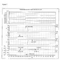
- the graphs of the figure 7 illustrate a simulation of the electronic system according to the invention in an emergency mode of the application.
- the simulation of the figure 6 was made with an electronic system as illustrated on the figure 4 .
- the first graph shows the state of the switches
- the second graph shows the current supplied through the transition diode
- the third graph shows the current through the load branch
- the fourth graph shows the current through the discharge branch
- the last graph shows the voltage across the battery.
- the battery is initially charged with an 80% SOC; the charger holds the load (switch K3C in the closed position), the charging switch K3S is in the closed position and the discharge switch K2 is in position opened.
- the Electronic control unit will control the closing of the K2C discharge switch and the opening of the K3C charger switch to stop charging.
- the electronic control unit detects an emergency mode, it keeps the K3S charge switch in the open position and it inhibits all the safety of the battery so as not to slow down the power supply of the backup battery.
- the potential of the application may become greater than the potential of the battery while the emergency mode is still active, for example because the battery reaches a relatively low charge state compared to the main supply voltage.
- the battery could then go into a charging phase with a flow of current from the application to the battery through the power line of the discharge circuit 20.
- the electronic control unit if it detects a potential of the battery lower than that of the application network while a backup mode is active, will operate the opening of the discharge switch K2 in order to prevent charging of the battery from the application whose main power supply has failed. As soon as the discharge becomes possible, even before the discharge switch K2 is closed again, the electric power of the battery is again available through the diode of the charging circuit D3. Any discontinuity of power availability is thus avoided.
- the electronic unit controls the opening of all the switches of the battery, including the second discharge switch K4 to prohibit the over-discharge of the batteries. battery cells.
- the backup battery according to the invention can thus be maintained in a state of charge close to 100% permanently from the main power supply.
- the application as long as it is not requested in its backup function or for a start of the APU.
- a particular application of such a backup battery can be envisaged for aircraft and especially for large drones that requires a large capacity; the backup battery can be charged by the main power of the aircraft as long as it is operational and can deliver electrical energy to the aircraft as soon as necessary without power discontinuity.
Landscapes
- Engineering & Computer Science (AREA)
- Power Engineering (AREA)
- Business, Economics & Management (AREA)
- Emergency Management (AREA)
- Charge And Discharge Circuits For Batteries Or The Like (AREA)
- Secondary Cells (AREA)
- Control Of Electrical Variables (AREA)
Abstract
Description
La présente invention se rapporte à un système électronique pour batterie comprenant au moins un accumulateur étanche.The present invention relates to an electronic system for battery comprising at least one sealed accumulator.
Un générateur électrochimique ou accumulateur (ces deux termes sont équivalents) est un dispositif de production d'électricité dans lequel de l'énergie chimique est convertie en énergie électrique. L'énergie chimique est constituée par des composés électrochimiquement actifs déposés sur au moins une face d'électrodes disposées dans l'accumulateur. L'énergie électrique est produite par des réactions électrochimiques au cours d'une décharge de l'accumulateur. Les électrodes, disposées dans un conteneur, sont connectées électriquement à des bornes de sortie de courant qui assurent une continuité électrique entre les électrodes et un consommateur électrique auquel l'accumulateur est associé.An electrochemical generator or accumulator (these two terms are equivalent) is a device for generating electricity in which chemical energy is converted into electrical energy. The chemical energy consists of electrochemically active compounds deposited on at least one electrode face disposed in the accumulator. The electrical energy is produced by electrochemical reactions during a discharge of the accumulator. The electrodes, disposed in a container, are electrically connected to current output terminals which provide electrical continuity between the electrodes and an electrical consumer with which the accumulator is associated.
La batterie est destinée à fournir de l'énergie électrique à une application extérieure ; un circuit de charge est donc généralement prévu auquel la batterie peut être branchée pour recharger les accumulateurs. Afin d'augmenter la puissance délivrée, il est connu d'associer plusieurs accumulateurs étanches entre eux pour former une batterie. La batterie comporte alors une ou plusieurs branches parallèles d'accumulateurs reliés en série. La gestion de la charge et de la décharge de la batterie peut alors être organisée et contrôlée pour équilibrer la charge et décharge des différents accumulateurs les uns par rapport aux autres. Un circuit de contrôle, plus ou moins évolué selon les applications, est généralement prévu pour être associé à la batterie.The battery is intended to supply electrical power to an outdoor application; a charging circuit is therefore generally provided to which the battery can be connected to recharge the batteries. In order to increase the power delivered, it is known to associate several sealed accumulators together to form a battery. The battery then has one or more parallel branches of accumulators connected in series. The management of the charging and discharging of the battery can then be organized and controlled to balance the charging and discharging of the different accumulators relative to each other. A control circuit, more or less evolved according to the applications, is generally intended to be associated with the battery.
Pour des applications à des batteries de secours, il est important que les accumulateurs soient chargés à leur pleine capacité avant leur utilisation, mais surtout que l'énergie soit instantanément disponible.For battery backup applications it is important that the batteries are charged to their full capacity before use, but especially that the energy is instantly available.
Les aéronefs ou autres véhicules de transport utilisent généralement des batteries au plomb ou de type Nickel Cadmium (NiCd) pour assurer le démarrage du véhicule et une alimentation de secours. Ces batteries peuvent rester connectées à l'alimentation principale et être chargées tant qu'elles ne sont pas sollicitées ; aucune surcharge des accumulateurs n'est à craindre. Or, il est apparu souhaitable de pouvoir utiliser des batteries de type Li-Ion comme batterie de secours, notamment pour des applications aux aéronefs afin de pouvoir bénéficier d'une réduction de poids et d'une facilité d'entretien propre à ce type de batterie. Cependant, les batteries de type Li-Ion requièrent une gestion de charge spécifique afin d'éviter toute surcharge. Il a en effet été observé que la surcharge d'accumulateurs Li-Ion provoque un vieillissement prématuré de la batterie. Il n'est donc pas possible de remplacer directement une batterie NiCd ou plomb par une batterie Li-Ion ; un système électronique de gestion de la batterie doit être prévu pour contrôler la charge et l'équilibrage des accumulateurs Li-Ion.Aircraft or other transport vehicles typically use lead-acid batteries or Nickel Cadmium (NiCd) batteries to start the vehicle and provide emergency power. These batteries can remain connected to the main power supply and be charged as long as they are not used; no overcharging of the accumulators is to be feared. However, it has been found desirable to be able to use Li-Ion type batteries as backup battery, especially for aircraft applications in order to benefit from a reduction in weight and ease of maintenance specific to this type of aircraft. drums. However, Li-Ion batteries require specific charge management to avoid overcharging. It has indeed been observed that the overcharging of Li-Ion accumulators causes premature aging of the battery. It is therefore not possible to directly replace a NiCd or lead battery with a Li-Ion battery; a system Battery management electronics should be provided to control the charging and balancing of Li-Ion batteries.
En outre, il est souhaitable qu'une batterie de secours puisse délivrer de l'énergie électrique à l'application à laquelle elle est destinée de manière rapide, fiable et sans discontinuité lorsque l'alimentation principale de l'application est défaillante.In addition, it is desirable that a backup battery can deliver electrical power to the application for which it is intended quickly, reliably and without discontinuity when the main power supply of the application is defective.
Il existe donc un besoin pour une batterie qui puisse être chargée en permanence sans risque de surcharge tant qu'elle n'est pas sollicitée par l'application extérieure et qui puisse fournir de l'énergie électrique sans discontinuité lorsqu'elle est sollicitée.There is therefore a need for a battery that can be permanently charged without risk of overload as long as it is not requested by the external application and can provide electrical energy without discontinuity when it is requested.
A cet effet, l'invention propose un système électronique pour batterie, notamment pour batterie de secours, qui permet de contrôler la charge des accumulateurs afin de maintenir un état de charge optimal sans surcharge et qui permet d'assurer une décharge fiable sans interruption de puissance lorsque la batterie est sollicitée.For this purpose, the invention proposes an electronic system for a battery, in particular for a backup battery, which makes it possible to control the charge of the accumulators in order to maintain an optimal state of charge without overloading and which makes it possible to ensure a reliable discharge without interruption of power when the battery is in use.
Plus particulièrement, l'invention concerne un système électronique pour batterie destinée à fournir une énergie électrique à une application comprenant une alimentation principale, le système électronique comprenant:
- un circuit de charge de la batterie comprenant un chargeur ;
- un premier circuit de décharge de la batterie parallèle au circuit de charge et comprenant un commutateur de décharge ;
- un élément de continuité de la décharge ;
- une unité électronique de contrôle adaptée à commander l'ouverture et la fermeture du commutateur de décharge et adaptée à contrôler le chargeur ;
- assure un maintien de la charge de la batterie tant que celle-ci n'est pas sollicitée en décharge ;
- interrompt la charge de la batterie et actionne le commutateur de décharge en position fermée lorsqu'une sollicitation de l'application est détectée,
et dans lequel l'élément de continuité de la décharge permet un passage d'un courant de décharge durant une phase de transition de fermeture du commutateur de décharge.
- a charging circuit of the battery comprising a charger;
- a first discharge circuit of the battery parallel to the charging circuit and comprising a discharge switch;
- an element of continuity of the discharge;
- an electronic control unit adapted to control the opening and closing of the discharge switch and adapted to control the charger;
- maintains the charge of the battery as long as the battery is not used for discharging;
- interrupts the charge of the battery and actuates the discharge switch in the closed position when a solicitation of the application is detected,
and wherein the continuity element of the discharge allows a discharge current to pass during a closing transition phase of the discharge switch.
Selon un mode de réalisation, l'élément de continuité de la décharge est disposé dans le circuit de charge qui est une branche bidirectionnelle. Le circuit de charge peut comprendre un commutateur de charge disposé en série avec le chargeur et une diode disposée en parallèle du chargeur, la diode permettant la décharge de la batterie lorsque le commutateur de charge est en position fermée et le chargeur interrompu.According to one embodiment, the continuity element of the discharge is disposed in the load circuit which is a bidirectional branch. The charging circuit may comprise a charging switch arranged in series with the charger and a diode arranged in parallel with the charger, the diode allowing the discharge of the battery when the charge switch is in the closed position and the charger interrupted.
Selon un autre mode de réalisation, l'élément de continuité de la décharge est une diode de décharge disposée dans le circuit de décharge en parallèle du commutateur de décharge.According to another embodiment, the continuity element of the discharge is a discharge diode disposed in the parallel discharge circuit of the discharge switch.
Selon un mode de réalisation, le circuit de charge ne permet pas un passage de courant supérieur à 80A.According to one embodiment, the charging circuit does not allow a current flow greater than 80A.
Selon un mode de réalisation, l'unité de contrôle actionne le commutateur de décharge en position ouverte lorsque le potentiel de la batterie devient inférieur au potentiel de l'application.According to one embodiment, the control unit actuates the discharge switch in the open position when the potential of the battery becomes lower than the potential of the application.
Selon un mode de réalisation, le système comprend en outre un deuxième circuit de décharge de la batterie parallèle au premier circuit de décharge et comprenant un deuxième commutateur de décharge maintenu en position fermée, une résistance limitant le passage du courant de décharge et une diode interdisant la charge de la batterie à travers le deuxième commutateur de décharge.According to one embodiment, the system further comprises a second discharge circuit of the battery parallel to the first discharge circuit and comprising a second discharge switch held in closed position, a resistor limiting the passage of the discharge current and a diode prohibiting charging the battery through the second discharge switch.
Selon des modes de réalisation, la résistance du deuxième circuit de décharge peut limiter le courant de décharge à 5A ; et le deuxième commutateur de décharge peut être maintenu en position fermée tant que l'état de charge de la batterie est supérieur à 20%.According to embodiments, the resistance of the second discharge circuit can limit the discharge current to 5A; and the second discharge switch can be held in the closed position as long as the state of charge of the battery is greater than 20%.
Selon un mode de réalisation, le système comprend en outre un troisième circuit de décharge de la batterie parallèle au premier circuit de décharge et comprenant un troisième commutateur de décharge actionné en position fermée lorsqu'une phase de démarrage de l'application est détectée. Le troisième commutateur de décharge peut permettre un passage de courant supérieur à 1500AAccording to one embodiment, the system further comprises a third discharge circuit of the battery parallel to the first discharge circuit and comprising a third discharge switch actuated in the closed position when a start phase of the application is detected. The third discharge switch can allow a current flow greater than 1500A
Selon un mode de réalisation, le système comprend en outre un commutateur de sécurité disposé en série avec le circuit de charge et en série avec le premier circuit de décharge et actionné en position ouverte lorsqu'une situation dangereuse pour l'utilisateur de la batterie est détectée. Le commutateur de sécurité est disposé en parallèle avec le deuxième circuit de décharge.According to one embodiment, the system further comprises a safety switch arranged in series with the charging circuit and in series with the first discharge circuit and actuated in the open position when a dangerous situation for the user of the battery is detected. The safety switch is arranged in parallel with the second discharge circuit.
L'invention concerne aussi une batterie rechargeable comprenant au moins un accumulateur électrochimique étanche et un système électronique selon l'invention. L'accumulateur étanche peut être de type Lithium-Ion. Une telle batterie peut être utilisée pour un aéronef par exemple.The invention also relates to a rechargeable battery comprising at least one sealed electrochemical accumulator and an electronic system according to the invention. The sealed accumulator may be of the Lithium-Ion type. Such a battery can be used for an aircraft for example.
D'autres caractéristiques et avantages de l'invention apparaîtront à la lecture de la description qui suit, donnée à titre d'exemple et en référence aux figures qui montrent :
-
Figure 1 , une vue schématique du système électronique selon un premier mode de réalisation de l'invention ; -
Figure 2 , une vue schématique du système électronique selon un deuxième mode de réalisation de l'invention ; -
Figure 3 , une vue schématique du système électronique selon un troisième mode de réalisation de l'invention ; -
Figure 4 , une vue schématique du système électronique selon un quatrième mode de réalisation de l'invention ; -
Figure 5 , une vue schématique du système électronique selon un cinquième mode de réalisation de l'invention ; -
Figure 6 , des graphes montrant un état des commutateurs, l'allure du courant délivré par la batterie et l'allure de la tension aux bornes de la batterie lors d'une simulation du démarrage de l'application avec une batterie comprenant un système électronique selon le quatrième mode de réalisation de l'invention ; -
Figure 7 , des graphes montrant un état des commutateurs, l'allure du courant délivré par la batterie et l'allure de la tension aux bornes de la batterie lors d'une simulation en mode secours avec une batterie comprenant un système électronique selon le quatrième mode de réalisation de l'invention.
-
Figure 1 a schematic view of the electronic system according to a first embodiment of the invention; -
Figure 2 , a schematic view of the electronic system according to a second embodiment of the invention; -
Figure 3 , a schematic view of the electronic system according to a third embodiment of the invention; -
Figure 4 , a schematic view of the electronic system according to a fourth embodiment of the invention; -
Figure 5 , a schematic view of the electronic system according to a fifth embodiment of the invention; -
Figure 6 , graphs showing a state of the switches, the pace of the current delivered by the battery and the pace of the voltage across the battery when simulating the start of the application with a battery comprising an electronic system according to the fourth embodiment of the invention; -
Figure 7 , graphs showing a state of the switches, the pace of the current delivered by the battery and the pace of the voltage at the battery terminals during a simulation in emergency mode with a battery comprising an electronic system according to the fourth mode of embodiment of the invention.
L'invention concerne un système électronique pour batterie comprenant au moins un accumulateur électrochimique rechargeable. La batterie est reliée en permanence à un bus de puissance d'une alimentation principale de l'application à laquelle elle est destinée. Le système électronique de l'invention contrôle la charge des accumulateurs afin d'éviter toute surcharge et garantit la continuité de la disponibilité en puissance électrique lorsque la batterie est sollicitée en décharge.The invention relates to an electronic system for a battery comprising at least one rechargeable electrochemical accumulator. The battery is permanently connected to a power bus of a main power supply of the application for which it is intended. The electronic system of the invention controls the charge of the accumulators in order to avoid any overload and guarantees the continuity of the availability of electrical power when the battery is requested for discharge.
L'invention s'applique notamment à une batterie de secours, c'est-à-dire une batterie destinée à fournir de l'énergie électrique à une application extérieure en cas de défaillance de l'alimentation principale. La batterie peut également être sollicitée pour un démarrage d'une unité auxiliaire de puissance (APU pour « Auxialiary Power Unit » en anglais) de l'application. L'application peut être un véhicule, par exemple un avion.The invention applies in particular to a backup battery, that is to say a battery for supplying electrical power to an external application in case of failure of the main power supply. The battery can also be requested for a start of an auxiliary power unit (APU for "Auxialiary Power Unit" in English) of the application. The application can be a vehicle, for example an airplane.
Les
Le circuit de décharge 20 comprend une ligne de puissance permettant la circulation d'un courant électrique de la batterie vers l'application et un commutateur K2 disposé sur cette ligne de puissance. Le commutateur K2 est maintenu en position ouverte tant que la batterie n'est pas sollicitée en décharge par l'application et il est actionné en position fermée lorsqu'une énergie électrique est requise par l'application. On entend par « position ouverte » du commutateur une position interdisant tout passage de courant et par « position fermée » du commutateur une position autorisant un passage de courant. Le circuit de décharge 20 peut comprendre en outre une diode D2 qui est disposée en parallèle du commutateur K2 (
Le circuit de charge 30 comprend un chargeur et peut comprendre une diode D3 en anti-parallèle. Selon le mode de réalisation illustré sur la
Sur la
Le circuit de décharge 30 ne permet pas le passage de courants forts, par exemple des courants supérieurs à 80A, qui sont nécessaires lorsque l'alimentation principale est défaillante. Le commutateur de décharge K3S n'est pas dimensionné pour de forts courants et le passage à travers la diode D3 introduit une impédance qui limite le courant disponible pour l'application. La décharge à travers le circuit de charge 30 est donc transitoire et permet seulement de garantir une disponibilité en courant immédiate en attendant que le commutateur de décharge K2 soit actionné en position fermée.The
Selon le mode de réalisation illustré sur la
Le système électronique selon l'invention comprend aussi une unité électronique de contrôle qui supervise le fonctionnement de la batterie afin de réguler la charge des accumulateurs et autoriser la décharge de la batterie lorsque l'application le requiert. Une telle unité de contrôle reçoit des informations provenant de l'application elle-même (potentiel de l'alimentation principale, température, alarme pour passage en mode secours et autres), de capteurs disposés dans la batterie (par exemple tension, courant et température de chaque accumulateur) et des informations quant au statut (position ouverte ou position fermée) des différents commutateurs du système électronique. L'unité électronique de contrôle peut ainsi assurer un maintien de la charge de la batterie sans risque de surcharge ; elle peut aussi détecter un besoin en énergie électrique de l'application et commander l'arrêt du chargeur et l'actionnement du commutateur K2 du circuit de décharge.The electronic system according to the invention also comprises an electronic control unit which supervises the operation of the battery in order to regulate the charge of the accumulators and to allow the discharge of the battery when the application requires it. Such a control unit receives information from the application itself (potential of the main power supply, temperature, alarm for switching to emergency mode and others), sensors arranged in the battery (for example voltage, current and temperature). each accumulator) and status information (open position or closed position) of the different switches of the electronic system. The electronic control unit can thus maintain the charge of the battery without risk of overcharging; it can also detect a need for electrical energy of the application and control the stopping of the charger and the actuation of the switch K2 of the discharge circuit.
Le chargeur du circuit de charge 30 est relié au réseau de l'alimentation principale de l'application. Par exemple, dans le cas d'une utilisation comme batterie d'avion ou de drone, le chargeur est relié au réseau 28V de l'aéronef afin d'assurer un maintien de la charge de la batterie à environ 100% de sa capacité. Dans le cas d'une batterie de type Li-Ion, le chargeur limite le courant de charge pour éviter tout dépôt de lithium sur les électrodes. L'unité électronique commande non seulement le commutateur du chargeur K3C mais également le commutateur de charge K3S si présent et assure un contrôle de la tension de charge à environ 4V par élément électrochimique de la batterie. L'unité électronique reçoit un signal quant au statut (position ouverte ou position fermée) des différents commutateurs K3S_statut, K3C_statut et K2_statut.The charging
La
La
Ce deuxième circuit de décharge 40 permet une utilisation de la batterie sous courants faibles, notamment lorsque l'électronique des branches principales de charge 30 et de décharge 20 est endormie en mode « stand-by », c'est-à-dire avec les commutateurs K2, K3C et K3S en positions ouvertes. Par exemple, pour une utilisation comme batterie d'avion, lorsque l'appareil est au sol, le deuxième circuit de décharge 40 peut être utilisé pour alimenter des veilleuses lors de l'entretien de l'appareil sans pour autant réveiller toute l'électronique de contrôle de la batterie qui consommerait plus d'énergie électrique que les besoins requis par l'application. La résistance R, associée à un déclencheur en courant « current trigger », permet de limiter le passage d'un courant de décharge dans cette branche 40 à environ 5A. Un tel courant est donc insignifiant lorsque la batterie est déchargée via sa branche principale 20 mais suffisant pour des applications d'entretien et de maintenance au sol. Un tel courant représente également une fuite négligeable lorsque la batterie est chargée par le circuit de charge 30. Si un appel en courant plus fort est requis par l'application, l'unité électronique de contrôle du système réveille les autres branches et actionne le commutateur de décharge K2 en position fermée.This
Le deuxième commutateur de décharge K4 reste toujours en position fermée ; l'unité électronique de contrôle n'a donc pas à l'actionner en position fermée et cette branche de décharge 40 peut être utilisée lorsque le système électronique est en mode « stand by ». Le deuxième commutateur de décharge K4 sera actionné en position ouverte si un état de charge de la batterie (SOC : State of Charge) inférieur à 20% est détecté afin de supprimer tout courant de fuite.The second discharge switch K4 always remains in the closed position; the electronic control unit does not have to operate in the closed position and this
La
La
Lors d'une phase de démarrage de l'unité auxiliaire de puissance APU, de très forts courants sont requis sur une courte période ; par exemple des courants pouvant atteindre 1500A sur moins de 10 secondes sont appelés à circuler de la batterie vers l'application. De tels courants créent des arcs électriques importants lors de l'ouverture des commutateurs et accélèrent le vieillissement des commutateurs. Ce troisième circuit de décharge 10 permet de préserver la fiabilité des commutateurs, notamment du commutateur de décharge K2 du premier circuit de décharge 20 qui sera utilisé dans un mode secours de la batterie. Le troisième commutateur K1 peut avoir les mêmes spécifications techniques que le commutateur K2 du premier circuit de décharge 20, ou présenter des caractéristiques de robustesse plus importantes. Le troisième commutateur K1 permet un passage de courant de plus de 1500A et le commutateur K2 du circuit de décharge principal 20 peut être préservé d'un passage de tels courants forts.During a start-up phase of the APU auxiliary power unit, very strong currents are required over a short period; for example currents up to 1500A in less than 10 seconds are expected to flow from the battery to the application. Such currents create significant arcing during the opening of the switches and accelerate the aging of the switches. This
La
Selon ce cinquième mode de réalisation, un commutateur de sécurité K2' a été ajouté en série avec le circuit de charge 30 et en série avec le premier circuit de décharge 20. La
Le cas échéant, le commutateur de sécurité K2' est en série avec le troisième circuit de décharge 10 de courants forts mais il est en parallèle avec le deuxième circuit de décharge 40 de courants faibles. Le commutateur de sécurité K2' est maintenu en position fermée et actionné en position ouverte si un défaut de la batterie est détecté et met l'utilisateur en situation dangereuse. Il constitue une redondance des commutateurs K1, K2, K3C et K3S.If necessary, the safety switch K2 'is in series with the
En mode « stand by », le commutateur de sécurité K2' est également en position ouverte. C'est pourquoi le deuxième circuit de décharge 40 de courants faibles doit être parallèle à ce commutateur de sécurité K2'. La présence du commutateur de sécurité K2' permet également d'assurer la décharge de transition soit par la diode D2 du circuit de décharge 20 soit par la diode D3 du circuit de charge 30. En effet, sans la présence de ce commutateur de sécurité K2', la présence d'une diode D2 parallèle au commutateur de décharge K2 garantirait un courant de décharge en mode « stand-by » et éliminerait le besoin d'une deuxième branche de décharge 40.In "stand by" mode, the safety switch K2 'is also in the open position. This is why the second weak
Sur la
En effet, en cas de défaillance de l'un de ces commutateurs K1, K2, K3S ou K3C qui resterait en position fermée alors que l'alimentation principale de l'application est opérationnelle, une utilisation mettant la batterie en situation dangereuse pourrait survenir et détériorer la batterie qui ne serait alors plus opérationnelle en mode secours. Le commutateur K2' serait alors actionné en position ouverte par l'électronique de contrôle. K2' reste dans une position fermée tant qu'aucune situation dangereuse pour l'utilisateur n'est pas détectée, sauf lors des périodes de stockage de la batterie.Indeed, in case of failure of one of these switches K1, K2, K3S or K3C which would remain in closed position while the main power of the application is operational, a use putting the battery in a dangerous situation could occur and damage the battery, which would no longer be operational in emergency mode. The switch K2 'would then be actuated in the open position by the control electronics. K2 'remains in a closed position as long as no dangerous situation for the user is detected except during storage periods of the battery.
Le système électronique selon l'invention fonctionne de la manière suivante.The electronic system according to the invention operates as follows.
Les graphes de la
La batterie est initialement chargée à sa pleine capacité ; elle a une tension sensiblement égale à celle du réseau 28V de l'alimentation principale de l'application et elle ne fournit ni ne reçoit aucun courant. Le chargeur est interrompu (commutateur K3C en position ouverte) et le commutateur de décharge K2 est en position ouverte. En revanche, le commutateur de charge K3S est en position fermée ; en cas d'appel en courant de l'application, avant même que l'un des commutateurs de décharge K1 ou K2 soit actionné, une décharge sera possible à travers la diode D3 du circuit de charge 30. La charge de la batterie reste cependant impossible tant que le commutateur du chargeur K3C n'est pas activé. Une disponibilité en courant immédiate est ainsi assurée.The battery is initially charged to full capacity; it has a voltage substantially equal to that of the 28V network of the main supply of the application and it does not supply or receive any current. The charger is interrupted (K3C switch in the open position) and the discharge switch K2 is in the open position. On the other hand, the charging switch K3S is in the closed position; in case of a current call from the application, even before one of the discharge switches K1 or K2 is actuated, a discharge will be possible through the diode D3 of the charging
Pour un démarrage de l'unité auxiliaire de puissance APU, l'unité électronique de contrôle va commander la fermeture du troisième commutateur de décharge K1 pour autoriser la circulation d'un courant de forte amplitude et l'ouverture du commutateur de charge K3S pour éviter tout retour de courant vers la batterie. Lorsque l'appel en courant diminue, en deçà de 100A par exemple, le premier circuit de décharge 20 prend le relais sur le troisième circuit de décharge 10 pour fournir l'énergie électrique à l'application ; le premier commutateur de décharge K2 est actionné en position fermée et le troisième commutateur de décharge K1 est actionné en position ouverte. La décharge peut être conduite à de très fortes puissances relativement à la charge, sans interruption de puissance lorsque la batterie est sollicitée. La dissymétrie des courants disponibles en charge par rapport à la décharge est due à l'électrochimie Li-ion et à la possibilité de dépôt de lithium lors de charges trop rapides, qui réduirait considérablement ses performances et sa durée de vie.For a start of the auxiliary power unit APU, the electronic control unit will control the closing of the third discharge switch K1 to allow the circulation of a high amplitude current and the opening of the load switch K3S to avoid any return of current to the battery. When the current call decreases, below 100A for example, the
Lorsque le démarrage de l'APU est terminé et que l'alimentation principale de l'application est activée, la batterie peut être rechargée. Le commutateur de décharge K2 est replacé en position ouverte, le commutateur de charge K3S est actionné en position fermée. Le commutateur du chargeur K3C sera activé si la tension du réseau est supérieure à la tension de la batterie. La charge de la batterie devient alors possible depuis le réseau de l'alimentation principale. La charge est régulée par la fermeture et l'ouverture du commutateur K3C du chargeur alors que le commutateur de charge K3S reste en position fermée. Une fois que la batterie a atteint un état de charge SOC de 100%, la charge est interrompue et le système électronique est placée en mode « stand-by » avec les commutateurs K1, K2, K3S et K3C en position ouverte. Seul le deuxième commutateur de décharge K4 reste en position fermée en mode « stand-by ».When the APU startup is complete and the application's main power is turned on, the battery can be recharged. The discharge switch K2 is returned to the open position, the charging switch K3S is actuated in the closed position. The K3C charger switch will be activated if the grid voltage is higher than the battery voltage. The charge of the battery then becomes possible from the main power supply network. The load is regulated by closing and opening the charger switch K3C while the charging switch K3S remains in the closed position. Once the battery has reached a 100% SOC state of charge, the charge is interrupted and the electronic system is placed in "stand-by" mode with the switches K1, K2, K3S and K3C in the open position. Only the second discharge switch K4 remains in the closed position in "stand-by" mode.
Les graphes de la
La batterie est initialement chargée avec un SOC de 80% ; le chargeur maintient la charge (commutateur K3C en position fermée), le commutateur de charge K3S est en position fermée et le commutateur de décharge K2 est en position ouverte. Lorsqu'une défaillance de l'alimentation principale est détectée, par exemple lorsque l'unité électronique de contrôle détecte une chute de tension dans le réseau électrique principal (comme illustré sur le dernier graphe) ou reçoit tout autre signal d'alarme, l'unité électronique de contrôle va commander la fermeture du commutateur de décharge K2 et l'ouverture du commutateur du chargeur K3C pour stopper la charge. Un courant de décharge aura cependant déjà pu circuler de la batterie vers l'application dès la chute de tension de l'alimentation principale, avant même que la fermeture du commutateur de décharge K2 soit effective, grâce à la diode D3 du circuit de charge 30. Une disponibilité immédiate en courant depuis la batterie est ainsi assurée pendant une période transitoire de 10 à 20 ms. Le circuit de charge 30 ne permet cependant pas le passage de courants forts. Lorsque le commutateur de décharge K2 est en position fermée, le courant circule à travers le circuit de décharge 20 qui a une impédance plus faible que le circuit de charge 30.The battery is initially charged with an 80% SOC; the charger holds the load (switch K3C in the closed position), the charging switch K3S is in the closed position and the discharge switch K2 is in position opened. When a failure of the main power supply is detected, for example when the electronic control unit detects a voltage drop in the main power grid (as shown in the last graph) or receives any other alarm signal, the Electronic control unit will control the closing of the K2C discharge switch and the opening of the K3C charger switch to stop charging. However, a discharge current has already been able to flow from the battery to the application at the voltage drop of the main power supply, even before the closing of the discharge switch K2 is effective, thanks to the diode D3 of the charging
Tant que l'unité électronique de contrôle détecte un mode secours, elle maintient le commutateur de charge K3S en position ouverte et elle inhibe toutes les sécurités de la batterie afin de ne pas freiner la disponibilité en courant de la batterie de secours.As long as the electronic control unit detects an emergency mode, it keeps the K3S charge switch in the open position and it inhibits all the safety of the battery so as not to slow down the power supply of the backup battery.
Dans certaines situations, le potentiel de l'application peut devenir supérieur au potentiel de la batterie alors que le mode secours est toujours actif, par exemple parce que la batterie atteint un état de charge relativement bas par rapport à la tension d'alimentation principale. La batterie pourrait alors passer dans une phase de charge avec une circulation de courant depuis l'application vers la batterie à travers la ligne de puissance du circuit de décharge 20.In some situations, the potential of the application may become greater than the potential of the battery while the emergency mode is still active, for example because the battery reaches a relatively low charge state compared to the main supply voltage. The battery could then go into a charging phase with a flow of current from the application to the battery through the power line of the
On cherche à éviter une telle situation. Pour cela, l'unité électronique de contrôle, si elle détecte un potentiel de la batterie plus faible que celui du réseau de l'application alors qu'un mode secours est actif, va actionner l'ouverture du commutateur de décharge K2 afin d'empêcher la recharge de la batterie depuis l'application dont l'alimentation principale est défaillante. Dès que la décharge redevient possible, avant même que le commutateur de décharge K2 ne soit refermé, l'énergie électrique de la batterie est à nouveau disponible à travers la diode du circuit de charge D3. Toute discontinuité de disponibilité de puissance est ainsi évitée.We try to avoid such a situation. For this, the electronic control unit, if it detects a potential of the battery lower than that of the application network while a backup mode is active, will operate the opening of the discharge switch K2 in order to prevent charging of the battery from the application whose main power supply has failed. As soon as the discharge becomes possible, even before the discharge switch K2 is closed again, the electric power of the battery is again available through the diode of the charging circuit D3. Any discontinuity of power availability is thus avoided.
En outre, lorsqu'un état de charge SOC inférieur à 20% est détecté, l'unité électronique commande l'ouverture de tous les commutateurs de la batterie, y compris le deuxième commutateur de décharge K4 afin d'interdire la sur-décharge des cellules de la batterie.In addition, when a charge state SOC of less than 20% is detected, the electronic unit controls the opening of all the switches of the battery, including the second discharge switch K4 to prohibit the over-discharge of the batteries. battery cells.
La batterie de secours selon l'invention peut ainsi être maintenue dans un état de charge proche de 100% en permanence à partir de l'alimentation principale de l'application, tant qu'elle n'est pas sollicitée dans sa fonction de secours ou pour un démarrage de l'APU. Une application particulière d'une telle batterie de secours peut être envisagée pour des aéronefs et notamment pour des drones de grande envergure qui requiert une grande capacité ; la batterie de secours peut être chargée par l'alimentation principale de l'aéronef tant que celle-ci est opérationnelle et peut délivrer une énergie électrique à l'aéronef dès que nécessaire sans discontinuité de puissance.The backup battery according to the invention can thus be maintained in a state of charge close to 100% permanently from the main power supply. the application, as long as it is not requested in its backup function or for a start of the APU. A particular application of such a backup battery can be envisaged for aircraft and especially for large drones that requires a large capacity; the backup battery can be charged by the main power of the aircraft as long as it is operational and can deliver electrical energy to the aircraft as soon as necessary without power discontinuity.
Les modes de réalisation décrits ci-dessus et les figures doivent être considérées comme ayant été présentés à titre illustratif et non restrictif, et l'invention n'est pas censée être limitée aux détails fournis ici mais peut être modifiée en restant dans le cadre de la portée des revendications annexées. En particulier, la description a été faite en référence à des accumulateurs de type Li-Ion mais tout autre couple électrochimique pourrait être utilisé. De même, les commutateurs peuvent être de tout type connu et l'unité électronique peut être programmée pour contrôler la charge et la décharge de la batterie avec des valeurs de tensions et courants différentes de celles données dans les exemples.The embodiments described above and the figures should be considered as illustrative and not restrictive, and the invention is not intended to be limited to the details provided herein but may be modified within the scope of the present invention. the scope of the appended claims. In particular, the description has been made with reference to Li-Ion type accumulators but any other electrochemical couple could be used. Similarly, the switches can be of any known type and the electronic unit can be programmed to control the charging and discharging of the battery with values of voltages and currents different from those given in the examples.
Claims (15)
et dans lequel l'élément de continuité de la décharge (D2, D3) permet un passage d'un courant de décharge durant une phase de transition de fermeture du commutateur de décharge (K2).
and wherein the discharge continuity member (D2, D3) allows a discharge current to pass during a closing transition phase of the discharge switch (K2).
Applications Claiming Priority (1)
| Application Number | Priority Date | Filing Date | Title |
|---|---|---|---|
| FR0800464A FR2926934B1 (en) | 2008-01-29 | 2008-01-29 | ELECTRONIC SYSTEM FOR BATTERY |
Publications (3)
| Publication Number | Publication Date |
|---|---|
| EP2085268A2 true EP2085268A2 (en) | 2009-08-05 |
| EP2085268A3 EP2085268A3 (en) | 2010-09-08 |
| EP2085268B1 EP2085268B1 (en) | 2019-08-14 |
Family
ID=39618991
Family Applications (1)
| Application Number | Title | Priority Date | Filing Date |
|---|---|---|---|
| EP09290026.5A Active EP2085268B1 (en) | 2008-01-29 | 2009-01-13 | Electronic system for battery |
Country Status (4)
| Country | Link |
|---|---|
| US (1) | US8193773B2 (en) |
| EP (1) | EP2085268B1 (en) |
| JP (1) | JP2009183139A (en) |
| FR (1) | FR2926934B1 (en) |
Cited By (3)
| Publication number | Priority date | Publication date | Assignee | Title |
|---|---|---|---|---|
| FR3038787A1 (en) * | 2015-07-06 | 2017-01-13 | Snecma | METHOD OF SUPPLYING AND CONTROLLING AN ELECTRIC ACTUATOR, CORRESPONDING CONTROL MODULE, ACTUATOR AND TURBOMACHINE COMPRISING SAME |
| CN108268079A (en) * | 2018-01-25 | 2018-07-10 | 南京佰联信息技术有限公司 | Ground power supply output voltage method of adjustment and system and computer readable storage medium |
| FR3082068A1 (en) * | 2018-05-30 | 2019-12-06 | Blue Solutions | RECHARGEABLE DEVICE AND SYSTEM FOR STORING ELECTRICAL ENERGY, VEHICLE AND INSTALLATION PROVIDED WITH SUCH A SYSTEM |
Families Citing this family (12)
| Publication number | Priority date | Publication date | Assignee | Title |
|---|---|---|---|---|
| US8179092B2 (en) | 2010-04-12 | 2012-05-15 | Concorde Battery Corporation | Lithium-ion aircraft battery with automatically activated battery management system |
| DE102011081906A1 (en) * | 2011-08-31 | 2013-02-28 | Bayerische Motoren Werke Aktiengesellschaft | Electrochemical energy-storage system i.e. lithium ion battery, for vehicle, has energy storage device comprising unloading safety device such that energy storage device is discharged by unloading safety device after overload |
| JP6141302B2 (en) * | 2011-11-15 | 2017-06-07 | イサベルク・ラピッド・エービーIsaberg Rapid Ab | Detector arrangement in current circuit arrangement with standby shutdown |
| US9041344B2 (en) | 2012-05-25 | 2015-05-26 | Timotion Technology Co., Ltd. | Standby battery box for electric cylinder |
| DK177581B1 (en) * | 2012-05-31 | 2013-10-28 | Timotion Technology Co Ltd | Standby battery box for electric cylinder |
| TWI477017B (en) * | 2012-07-24 | 2015-03-11 | Lite On Technology Corp | Control system, power supply system, and method for preventing floating charge of battery |
| JP6260106B2 (en) | 2013-04-25 | 2018-01-17 | 株式会社Gsユアサ | Power storage device |
| JP6412757B2 (en) * | 2014-09-30 | 2018-10-24 | Fdk株式会社 | Power supply |
| JP6665551B2 (en) | 2016-01-22 | 2020-03-13 | 株式会社Gsユアサ | Battery device and method for determining unauthorized use of secondary battery |
| CN109659993A (en) * | 2018-12-10 | 2019-04-19 | 深圳供电局有限公司 | Afterflow device and unmanned aerial vehicle power supply system |
| US11735932B2 (en) | 2021-10-30 | 2023-08-22 | Beta Air, Llc | System and methods for an immediate shutdown of an electric vehicle charger |
| US11705743B2 (en) | 2021-10-30 | 2023-07-18 | Beta Air, Llc | Systems and methods for emergency shutdown of an electric charger in response to a disconnection |
Citations (1)
| Publication number | Priority date | Publication date | Assignee | Title |
|---|---|---|---|---|
| JP2000224769A (en) | 1999-01-28 | 2000-08-11 | Shikoku Electric Power Co Inc | Distributed battery system |
Family Cites Families (21)
| Publication number | Priority date | Publication date | Assignee | Title |
|---|---|---|---|---|
| US4163934A (en) * | 1977-07-06 | 1979-08-07 | Francis Lawn | Methods and apparatus for charging batteries |
| US5293076A (en) * | 1991-04-16 | 1994-03-08 | Mitsubishi Denki Kabushiki Kaisha | Vehicle control apparatus |
| JP3154503B2 (en) * | 1991-04-16 | 2001-04-09 | 三菱電機株式会社 | Internal combustion engine control device |
| JPH04318238A (en) * | 1991-04-17 | 1992-11-09 | Mitsubishi Electric Corp | Internal combustion engine control device |
| JPH04318239A (en) * | 1991-04-18 | 1992-11-09 | Mitsubishi Electric Corp | Internal combustion engine control device |
| JPH06113469A (en) * | 1992-09-25 | 1994-04-22 | Yuasa Corp | Charging system for enclosed battery for railway vehicle |
| JP2708374B2 (en) * | 1994-07-26 | 1998-02-04 | インターナショナル・ビジネス・マシーンズ・コーポレイション | Computer battery connection device and battery switching method |
| JP3228102B2 (en) * | 1995-11-29 | 2001-11-12 | 三菱電機株式会社 | Solar cell power supply |
| JPH10201129A (en) * | 1996-12-27 | 1998-07-31 | Japan Storage Battery Co Ltd | Power generation installation making use of solar energy |
| EP0901699A4 (en) * | 1997-01-31 | 1999-10-27 | Silverline Power Conversation | Uninterruptible power supply |
| US5909103A (en) * | 1997-07-24 | 1999-06-01 | Siliconix Incorporated | Safety switch for lithium ion battery |
| US6074775A (en) * | 1998-04-02 | 2000-06-13 | The Procter & Gamble Company | Battery having a built-in controller |
| US6075343A (en) * | 1999-02-12 | 2000-06-13 | Quanta Computer Inc. | Rechargeable battery pack module |
| JP4572018B2 (en) * | 2000-04-27 | 2010-10-27 | 富士通株式会社 | Battery pack and electronic system |
| US20050007071A1 (en) * | 2003-05-23 | 2005-01-13 | Jens Colberg | Circuit arrangement for an autonomous power supply system, and a method for its operation |
| US7786619B2 (en) * | 2003-09-12 | 2010-08-31 | The Chamberlain Group, Inc. | DC power backup |
| JP2005160251A (en) * | 2003-11-27 | 2005-06-16 | Ntt Power & Building Facilities Inc | Power supply system |
| JP4367374B2 (en) * | 2005-05-16 | 2009-11-18 | パナソニック株式会社 | Power storage device |
| US20070273216A1 (en) * | 2006-05-24 | 2007-11-29 | Farbarik John M | Systems and Methods for Reducing Power Losses in a Medical Device |
| FR2925789A1 (en) * | 2007-12-20 | 2009-06-26 | Commissariat Energie Atomique | ELECTRICAL CONVERTER WITH VARIABLE CAPACITY |
| WO2011074196A1 (en) * | 2009-12-16 | 2011-06-23 | パナソニック株式会社 | Battery pack, discharge system, charge/discharge system, and discharge control method for lithium ion rechargeable battery |
-
2008
- 2008-01-29 FR FR0800464A patent/FR2926934B1/en active Active
-
2009
- 2009-01-13 EP EP09290026.5A patent/EP2085268B1/en active Active
- 2009-01-23 US US12/359,057 patent/US8193773B2/en not_active Expired - Fee Related
- 2009-01-28 JP JP2009016902A patent/JP2009183139A/en active Pending
Patent Citations (1)
| Publication number | Priority date | Publication date | Assignee | Title |
|---|---|---|---|---|
| JP2000224769A (en) | 1999-01-28 | 2000-08-11 | Shikoku Electric Power Co Inc | Distributed battery system |
Cited By (3)
| Publication number | Priority date | Publication date | Assignee | Title |
|---|---|---|---|---|
| FR3038787A1 (en) * | 2015-07-06 | 2017-01-13 | Snecma | METHOD OF SUPPLYING AND CONTROLLING AN ELECTRIC ACTUATOR, CORRESPONDING CONTROL MODULE, ACTUATOR AND TURBOMACHINE COMPRISING SAME |
| CN108268079A (en) * | 2018-01-25 | 2018-07-10 | 南京佰联信息技术有限公司 | Ground power supply output voltage method of adjustment and system and computer readable storage medium |
| FR3082068A1 (en) * | 2018-05-30 | 2019-12-06 | Blue Solutions | RECHARGEABLE DEVICE AND SYSTEM FOR STORING ELECTRICAL ENERGY, VEHICLE AND INSTALLATION PROVIDED WITH SUCH A SYSTEM |
Also Published As
| Publication number | Publication date |
|---|---|
| US20090189568A1 (en) | 2009-07-30 |
| US8193773B2 (en) | 2012-06-05 |
| EP2085268B1 (en) | 2019-08-14 |
| JP2009183139A (en) | 2009-08-13 |
| FR2926934B1 (en) | 2010-09-17 |
| EP2085268A3 (en) | 2010-09-08 |
| FR2926934A1 (en) | 2009-07-31 |
Similar Documents
| Publication | Publication Date | Title |
|---|---|---|
| EP2085268B1 (en) | Electronic system for battery | |
| EP2452384B1 (en) | Low-loss storage battery | |
| EP1265336B1 (en) | Equalisation method for an electric battery in a discontinuous recharging mode and battery management system for carrying out the same | |
| EP1202426B1 (en) | Universal battery charger and method | |
| FR2908939A1 (en) | Main power bus voltage regulation assuring device for satellite, has control signal generating unit for generating control signal determining closing and opening of switch in specific cases | |
| EP2600462B1 (en) | Method for balancing the voltages of electrochemical cells arranged in a plurality of parallel arms | |
| WO2012120030A1 (en) | Charge balancing system for batteries | |
| EP2416468A2 (en) | Method for balancing a battery and battery management system implementing such a method | |
| FR2982998A1 (en) | BATTERY OF ACCUMULATORS PROTECTED AGAINST SHORT CIRCUITS | |
| WO2016083690A1 (en) | Battery pack for an automotive vehicle | |
| EP2309615B1 (en) | System and method for managing the charge of a battery | |
| WO2020074397A1 (en) | Method and device for controlling the level of charge of a traction battery of an electric vehicle | |
| EP2363939B1 (en) | AC uninterruptible power supply for an installation and method therefor | |
| EP2079125B1 (en) | Method for managing the charge of a battery | |
| EP3472911B1 (en) | Method and system for managing electrochemical batteries of a power supply facility in case of battery failure. | |
| FR2916578A1 (en) | ELECTRONIC SYSTEM FOR BATTERY. | |
| EP0077531A1 (en) | Charging device for a group of batteries, especially of buffer batteries fed by a limited power supply | |
| EP1701531A1 (en) | Voltage transient suppression circuit | |
| EP1829152B1 (en) | Method for maintaining the charge of a lead storage battery | |
| FR2810809A1 (en) | Battery supply system, e.g. for mobile phone, has higher voltage reserve battery improves autonomy | |
| FR3114453A1 (en) | Feeding device | |
| FR2849298A1 (en) | DEVICE FOR MONITORING THE CHARGE STATE, AT CONSTANT VOLTAGE, OF A BATTERY ASSEMBLY WITH SECONDARY ELECTROCHEMICAL GENERATORS | |
| FR2959631A1 (en) | Aircraft rechargeable lithium ion battery disconnecting system, has parallel branches, where each branch includes silicon switches that are mounted on metal isolated substrate card, where free wheel diode is equipped in system | |
| FR3022400A1 (en) | PROTECTING A BATTERY AGAINST EXTENDED LOAD ABSENCE | |
| FR3094680A1 (en) | MOTOR VEHICLE INCLUDING AN ELECTRICAL POWER SUPPLY CIRCUIT WITH DOUBLE LITHIUM ACCUMULATOR |
Legal Events
| Date | Code | Title | Description |
|---|---|---|---|
| PUAI | Public reference made under article 153(3) epc to a published international application that has entered the european phase |
Free format text: ORIGINAL CODE: 0009012 |
|
| AK | Designated contracting states |
Kind code of ref document: A2 Designated state(s): AT BE BG CH CY CZ DE DK EE ES FI FR GB GR HR HU IE IS IT LI LT LU LV MC MK MT NL NO PL PT RO SE SI SK TR |
|
| AX | Request for extension of the european patent |
Extension state: AL BA RS |
|
| PUAL | Search report despatched |
Free format text: ORIGINAL CODE: 0009013 |
|
| AK | Designated contracting states |
Kind code of ref document: A3 Designated state(s): AT BE BG CH CY CZ DE DK EE ES FI FR GB GR HR HU IE IS IT LI LT LU LV MC MK MT NL NO PL PT RO SE SI SK TR |
|
| AX | Request for extension of the european patent |
Extension state: AL BA RS |
|
| RIC1 | Information provided on ipc code assigned before grant |
Ipc: H02J 9/06 20060101ALI20100804BHEP Ipc: B60R 16/03 20060101ALI20100804BHEP Ipc: H02J 7/00 20060101AFI20100804BHEP |
|
| 17P | Request for examination filed |
Effective date: 20110308 |
|
| AKX | Designation fees paid |
Designated state(s): DE FR GB |
|
| 17Q | First examination report despatched |
Effective date: 20151015 |
|
| GRAP | Despatch of communication of intention to grant a patent |
Free format text: ORIGINAL CODE: EPIDOSNIGR1 |
|
| INTG | Intention to grant announced |
Effective date: 20190516 |
|
| GRAS | Grant fee paid |
Free format text: ORIGINAL CODE: EPIDOSNIGR3 |
|
| GRAA | (expected) grant |
Free format text: ORIGINAL CODE: 0009210 |
|
| AK | Designated contracting states |
Kind code of ref document: B1 Designated state(s): DE FR GB |
|
| REG | Reference to a national code |
Ref country code: GB Ref legal event code: FG4D Free format text: NOT ENGLISH |
|
| REG | Reference to a national code |
Ref country code: DE Ref legal event code: R096 Ref document number: 602009059441 Country of ref document: DE |
|
| REG | Reference to a national code |
Ref country code: DE Ref legal event code: R097 Ref document number: 602009059441 Country of ref document: DE |
|
| PLBE | No opposition filed within time limit |
Free format text: ORIGINAL CODE: 0009261 |
|
| STAA | Information on the status of an ep patent application or granted ep patent |
Free format text: STATUS: NO OPPOSITION FILED WITHIN TIME LIMIT |
|
| 26N | No opposition filed |
Effective date: 20200603 |
|
| PGFP | Annual fee paid to national office [announced via postgrant information from national office to epo] |
Ref country code: FR Payment date: 20210114 Year of fee payment: 13 |
|
| PG25 | Lapsed in a contracting state [announced via postgrant information from national office to epo] |
Ref country code: FR Free format text: LAPSE BECAUSE OF NON-PAYMENT OF DUE FEES Effective date: 20220131 |
|
| PGFP | Annual fee paid to national office [announced via postgrant information from national office to epo] |
Ref country code: GB Payment date: 20230131 Year of fee payment: 15 |
|
| PGFP | Annual fee paid to national office [announced via postgrant information from national office to epo] |
Ref country code: DE Payment date: 20240130 Year of fee payment: 16 |