EP2082839B1 - Konformes Saugnapfgerät und entsprechendes Verfahren - Google Patents
Konformes Saugnapfgerät und entsprechendes Verfahren Download PDFInfo
- Publication number
- EP2082839B1 EP2082839B1 EP09005809.0A EP09005809A EP2082839B1 EP 2082839 B1 EP2082839 B1 EP 2082839B1 EP 09005809 A EP09005809 A EP 09005809A EP 2082839 B1 EP2082839 B1 EP 2082839B1
- Authority
- EP
- European Patent Office
- Prior art keywords
- vacuum cup
- rail
- vacuum
- machining device
- flexible track
- Prior art date
- Legal status (The legal status is an assumption and is not a legal conclusion. Google has not performed a legal analysis and makes no representation as to the accuracy of the status listed.)
- Expired - Lifetime
Links
Images


Classifications
-
- B—PERFORMING OPERATIONS; TRANSPORTING
- B25—HAND TOOLS; PORTABLE POWER-DRIVEN TOOLS; MANIPULATORS
- B25B—TOOLS OR BENCH DEVICES NOT OTHERWISE PROVIDED FOR, FOR FASTENING, CONNECTING, DISENGAGING OR HOLDING
- B25B11/00—Work holders not covered by any preceding group in the subclass, e.g. magnetic work holders, vacuum work holders
- B25B11/005—Vacuum work holders
- B25B11/007—Vacuum work holders portable, e.g. handheld
-
- B—PERFORMING OPERATIONS; TRANSPORTING
- B25—HAND TOOLS; PORTABLE POWER-DRIVEN TOOLS; MANIPULATORS
- B25B—TOOLS OR BENCH DEVICES NOT OTHERWISE PROVIDED FOR, FOR FASTENING, CONNECTING, DISENGAGING OR HOLDING
- B25B11/00—Work holders not covered by any preceding group in the subclass, e.g. magnetic work holders, vacuum work holders
-
- B—PERFORMING OPERATIONS; TRANSPORTING
- B64—AIRCRAFT; AVIATION; COSMONAUTICS
- B64C—AEROPLANES; HELICOPTERS
- B64C3/00—Wings
-
- B—PERFORMING OPERATIONS; TRANSPORTING
- B23—MACHINE TOOLS; METAL-WORKING NOT OTHERWISE PROVIDED FOR
- B23Q—DETAILS, COMPONENTS, OR ACCESSORIES FOR MACHINE TOOLS, e.g. ARRANGEMENTS FOR COPYING OR CONTROLLING; MACHINE TOOLS IN GENERAL CHARACTERISED BY THE CONSTRUCTION OF PARTICULAR DETAILS OR COMPONENTS; COMBINATIONS OR ASSOCIATIONS OF METAL-WORKING MACHINES, NOT DIRECTED TO A PARTICULAR RESULT
- B23Q2210/00—Machine tools incorporating a specific component
- B23Q2210/008—Flexible guiding rails
-
- Y—GENERAL TAGGING OF NEW TECHNOLOGICAL DEVELOPMENTS; GENERAL TAGGING OF CROSS-SECTIONAL TECHNOLOGIES SPANNING OVER SEVERAL SECTIONS OF THE IPC; TECHNICAL SUBJECTS COVERED BY FORMER USPC CROSS-REFERENCE ART COLLECTIONS [XRACs] AND DIGESTS
- Y10—TECHNICAL SUBJECTS COVERED BY FORMER USPC
- Y10T—TECHNICAL SUBJECTS COVERED BY FORMER US CLASSIFICATION
- Y10T29/00—Metal working
- Y10T29/49—Method of mechanical manufacture
- Y10T29/49616—Structural member making
- Y10T29/49622—Vehicular structural member making
-
- Y—GENERAL TAGGING OF NEW TECHNOLOGICAL DEVELOPMENTS; GENERAL TAGGING OF CROSS-SECTIONAL TECHNOLOGIES SPANNING OVER SEVERAL SECTIONS OF THE IPC; TECHNICAL SUBJECTS COVERED BY FORMER USPC CROSS-REFERENCE ART COLLECTIONS [XRACs] AND DIGESTS
- Y10—TECHNICAL SUBJECTS COVERED BY FORMER USPC
- Y10T—TECHNICAL SUBJECTS COVERED BY FORMER US CLASSIFICATION
- Y10T29/00—Metal working
- Y10T29/49—Method of mechanical manufacture
- Y10T29/49826—Assembling or joining
- Y10T29/49947—Assembling or joining by applying separate fastener
- Y10T29/49954—Fastener deformed after application
- Y10T29/49956—Riveting
-
- Y—GENERAL TAGGING OF NEW TECHNOLOGICAL DEVELOPMENTS; GENERAL TAGGING OF CROSS-SECTIONAL TECHNOLOGIES SPANNING OVER SEVERAL SECTIONS OF THE IPC; TECHNICAL SUBJECTS COVERED BY FORMER USPC CROSS-REFERENCE ART COLLECTIONS [XRACs] AND DIGESTS
- Y10—TECHNICAL SUBJECTS COVERED BY FORMER USPC
- Y10T—TECHNICAL SUBJECTS COVERED BY FORMER US CLASSIFICATION
- Y10T29/00—Metal working
- Y10T29/49—Method of mechanical manufacture
- Y10T29/49998—Work holding
-
- Y—GENERAL TAGGING OF NEW TECHNOLOGICAL DEVELOPMENTS; GENERAL TAGGING OF CROSS-SECTIONAL TECHNOLOGIES SPANNING OVER SEVERAL SECTIONS OF THE IPC; TECHNICAL SUBJECTS COVERED BY FORMER USPC CROSS-REFERENCE ART COLLECTIONS [XRACs] AND DIGESTS
- Y10—TECHNICAL SUBJECTS COVERED BY FORMER USPC
- Y10T—TECHNICAL SUBJECTS COVERED BY FORMER US CLASSIFICATION
- Y10T29/00—Metal working
- Y10T29/51—Plural diverse manufacturing apparatus including means for metal shaping or assembling
- Y10T29/5104—Type of machine
- Y10T29/5105—Drill press
- Y10T29/5108—Portable
-
- Y—GENERAL TAGGING OF NEW TECHNOLOGICAL DEVELOPMENTS; GENERAL TAGGING OF CROSS-SECTIONAL TECHNOLOGIES SPANNING OVER SEVERAL SECTIONS OF THE IPC; TECHNICAL SUBJECTS COVERED BY FORMER USPC CROSS-REFERENCE ART COLLECTIONS [XRACs] AND DIGESTS
- Y10—TECHNICAL SUBJECTS COVERED BY FORMER USPC
- Y10T—TECHNICAL SUBJECTS COVERED BY FORMER US CLASSIFICATION
- Y10T29/00—Metal working
- Y10T29/51—Plural diverse manufacturing apparatus including means for metal shaping or assembling
- Y10T29/5116—Plural diverse manufacturing apparatus including means for metal shaping or assembling forging and bending, cutting or punching
- Y10T29/5118—Riveting
-
- Y—GENERAL TAGGING OF NEW TECHNOLOGICAL DEVELOPMENTS; GENERAL TAGGING OF CROSS-SECTIONAL TECHNOLOGIES SPANNING OVER SEVERAL SECTIONS OF THE IPC; TECHNICAL SUBJECTS COVERED BY FORMER USPC CROSS-REFERENCE ART COLLECTIONS [XRACs] AND DIGESTS
- Y10—TECHNICAL SUBJECTS COVERED BY FORMER USPC
- Y10T—TECHNICAL SUBJECTS COVERED BY FORMER US CLASSIFICATION
- Y10T29/00—Metal working
- Y10T29/51—Plural diverse manufacturing apparatus including means for metal shaping or assembling
- Y10T29/5191—Assembly
-
- Y—GENERAL TAGGING OF NEW TECHNOLOGICAL DEVELOPMENTS; GENERAL TAGGING OF CROSS-SECTIONAL TECHNOLOGIES SPANNING OVER SEVERAL SECTIONS OF THE IPC; TECHNICAL SUBJECTS COVERED BY FORMER USPC CROSS-REFERENCE ART COLLECTIONS [XRACs] AND DIGESTS
- Y10—TECHNICAL SUBJECTS COVERED BY FORMER USPC
- Y10T—TECHNICAL SUBJECTS COVERED BY FORMER US CLASSIFICATION
- Y10T29/00—Metal working
- Y10T29/53—Means to assemble or disassemble
- Y10T29/5313—Means to assemble electrical device
- Y10T29/53191—Means to apply vacuum directly to position or hold work part
-
- Y—GENERAL TAGGING OF NEW TECHNOLOGICAL DEVELOPMENTS; GENERAL TAGGING OF CROSS-SECTIONAL TECHNOLOGIES SPANNING OVER SEVERAL SECTIONS OF THE IPC; TECHNICAL SUBJECTS COVERED BY FORMER USPC CROSS-REFERENCE ART COLLECTIONS [XRACs] AND DIGESTS
- Y10—TECHNICAL SUBJECTS COVERED BY FORMER USPC
- Y10T—TECHNICAL SUBJECTS COVERED BY FORMER US CLASSIFICATION
- Y10T408/00—Cutting by use of rotating axially moving tool
- Y10T408/55—Cutting by use of rotating axially moving tool with work-engaging structure other than Tool or tool-support
-
- Y—GENERAL TAGGING OF NEW TECHNOLOGICAL DEVELOPMENTS; GENERAL TAGGING OF CROSS-SECTIONAL TECHNOLOGIES SPANNING OVER SEVERAL SECTIONS OF THE IPC; TECHNICAL SUBJECTS COVERED BY FORMER USPC CROSS-REFERENCE ART COLLECTIONS [XRACs] AND DIGESTS
- Y10—TECHNICAL SUBJECTS COVERED BY FORMER USPC
- Y10T—TECHNICAL SUBJECTS COVERED BY FORMER US CLASSIFICATION
- Y10T409/00—Gear cutting, milling, or planing
- Y10T409/30—Milling
- Y10T409/306216—Randomly manipulated, work supported, or work following device
- Y10T409/306384—Randomly manipulated, work supported, or work following device with work supported guide means
- Y10T409/30644—Randomly manipulated, work supported, or work following device with work supported guide means to guide tool to move in arcuate path
Definitions
- the present invention relates generally to manufacturing tools and automation. More particularly, the present invention relates to attachment of rail-mounted machine tools to work surfaces.
- Portable, vacuum-cup-attached systems for drilling or fastening sections of aircraft fuselage or wing structures, as well as for other manufacturing operations, for other vehicle types, and for static structures, have been developed previously, but have generally been most practical for use only on workpiece areas where the contour is zero or very small in the longitudinal direction of the device.
- some prior art vacuum cup systems could be attached readily along the flight direction of a cylindrical or otherwise highly curved fuselage, particularly where the fuselage has a long, essentially straight extent (i.e., a contour near zero), but attaching such a system to the fuselage in the circumferential direction, or fore-and-aft along a curving wing rib, would tend sometimes to produce uncertain results.
- Prior art systems that use small numbers of large vacuum cups have been used, but have tended to be unable to conform smoothly to severe contours.
- Prior art systems with large numbers of small vacuum cups can follow a contour to some extent, but tend to be limited in the available retaining force by the necessity of having physical clearance around each vacuum cup, and by the limited available length-to-width ratio of an individual cup.
- Prior art rail-mounted machine tool systems can possess the capability to advance a tool attached to a rail using a motor and gear apparatus integrated with the tool. Measurement apparatus, likewise integrated with the tool, allows the position of the tool to be determined with considerable precision. Nonetheless, prior art systems tend to be limited in their ability to conform to generalized surfaces, being best suited to positioning along low-contour paths.
- DE4203808 discloses a guide mounted on fixed areas on a flat level base. On or near the edge of the areas a seal of non porous plastics is fitted all round.
- the seal has a stable fixing, form and thickness and a flat surface whose width ensures adhesion to the base when the space enclosed by it is evacuated by a comparatively weak pump.
- the pump is connected to the spaces by small pipes through holes in the seal.
- US 2,946246 discloses a frame, with a shape dictated by the molding to be used and the contours of the body panel being drilled, having vacuum cups provided at spaced intervals thereon.
- the vacuum cups may be used to hold the fixture to the body panel.
- US 5,865,827 discloses a vacuum device that has a collapsible cover capable of maintaining a seal with a flexible surface such as human tissue.
- a set of shaping members support the cover against collapse into the evacuated region in the interior, yet readily flex to maintain the seal with the deforming tissue without the need for an excessive sealing force.
- the conformal vacuum cup described in some embodiments comprises a resilient cup member having a series of rigid stiffener elements oriented next to each other along the longitudinal axis of a rail system.
- a rail can be supported by attachment to the stiffener elements.
- the stiffener elements can be spaced away from the rail, in a representative embodiment, using standoff pins attached to the stiffener elements and to the rail. Between each pair of stiffener elements is a gap sufficient to allow the rail to flex over a comparatively sharply curved contour without interference.
- a group of stiffener elements assembled in a mold can be overmolded with an elastomeric material such as urethane, which overmolding encloses all of the stiffener elements and adds a circumferential lip to establish the vacuum cup.
- the vacuum cup so formed can have kerf shapes formed into the gaps between adjacent stiffener elements to permit substantial motion between the stiffener elements to permit substantial motion between the stiffener elements despite the presence of the overmolded elastomer.
- the above standoff pins can protrude from top and/or bottom surfaces of the overmolded elastomer.
- the vacuum cup for removable connection between a conformable, tool-carrying rail and a rail-side surface of a workpiece comprises an inner surface of the vacuum cup, an outer surface of the vacuum cup, a plurality of resilient pads joined into a contiguous whole (wherein the area between each pad and the rail-side surface of the workpiece defines a zone), a plurality of stiffener elements (wherein at least one of the plurality of stiffening elements is embedded at least partially within each respective one of the pads, and wherein the stiffener elements are attachable to the rail), and a resilient peripheral seal, joined to the pads and surrounding the periphery of all of the zones between the pads and the rail-side surface of the workpiece.
- the vacuum cup for removable connection between a conformable, tool-carrying rail and a rail-side surface of a workpiece may also include a plurality of standoff pins attached to the rail, where at least one of one of the standoff pins is attached to a respective one of each of the stiffener elements.
- an attachment between a rail with a longitudinal axis and a rail-side surface of the workpiece comprises means for stiffening a vacuum cup along an axis transverse to the longitudinal axis of the rail and parallel to the rail-side surface of the workpiece, means for removably sealing the stiffening means to the rail-side surface of the workpiece against vacuum loss, means for rigidly positioning a point on the rail with respect to a point on the rail-side surface of the workpiece, and means for coupling a vacuum source to a spatial volume occupying all of a space between the means for sealing and the rail-side surface of the work.piece.
- the flexible track machining device may be used in the following method; a method for removably attaching a rail with a longitudinal axis to a rail-side surface of a workpiece comprises stiffening a vacuum cup along an axis transverse to the longitudinal axis of the rail and parallel to the rail-side surface of the workpiece, removably sealing a perimeter of the vacuum cup to the rail-side surface of the workpiece against vacuum loss, rigidly positioning a point on the rail with respect to a point on the rail-side surface of the workpiece, and coupling a vacuum source to a spatial volume occupying all of a space between the vacuum cup and the rail-side surface of the workpiece.
- Various embodiments in accordance with the present invention provide vacuum cup apparatus and methods for attachment of devices such as, for example, a rail system used in operations such as drilling series of holes, which holes may be needed for assembling screws or rivets through airplane sheet surfaces into underlying structures.
- devices such as, for example, a rail system used in operations such as drilling series of holes, which holes may be needed for assembling screws or rivets through airplane sheet surfaces into underlying structures.
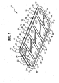
- FIG. 1 is an oblique bottom view that shows a fully compressed vacuum cup 10 according to an exemplary embodiment.
- the vacuum cup 10 has a peripheral sealing lip 12 that is shown deflected as it would be seen from below a transparent workpiece (a workpiece 70 is shown in FIGS. 7 and 11 ) when vacuum from an external vacuum system (shown in FIG. 10 ) has been applied to the volume between the cup 10 and the workpiece 70, and has caused outside air pressure to force the cup 10 against the workpiece 70.
- the exemplary vacuum cup 10 comprises two end pads 14 along with three intermediate pads 16. Each pad 14 or 16 comprises a stiffener (stiffeners 26 and 28 are shown in FIG.
- the standoff pin tops 22 can be attached to a rail using suitable fastenings (a rail 72 is shown in FIGS. 7 and 11 ).
- One or more partial holes 24 that are used to permit vacuum system attachment are shown in each end pad 14 and in more detail in FIGS. 5 and 6 .
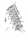
- FIG. 2 is an oblique cutaway view of the vacuum cup 10 from above. Representative pads 14 and 16 are shown cut away to reveal an end pad stiffener 26 and intermediate pad stiffeners 28 within their respective pads 14 and 16. Similar stiffeners are fully shown in FIGS. 3 and 4 .
- FIG. 3 is an oblique exploded view showing an end stiffener 30 substantially similar to the corresponding stiffener 26 in FIG. 2 .
- the stiffener 30 is shown with two standoff pins 18 oriented for insertion.
- Each of the exemplary standoff pins 18 in FIG. 3 has a pin top 22 with a chamfer 32 and a female thread 34 for attachment to a rail 72 (shown in FIGS. 7 and 11 ).
- a taper section 36 and an interference-fit section 38 on each standoff pin 18 can allow the pin 18 to be pressed substantially permanently into the corresponding hole 40.
- a shoulder 42 can provide an integral stop to allow the pin 18 to bear against the stiffener 26 or 30, with the pin bottom end 20 at a uniform distance from the bottom surface 44 of the stiffener 26 or 30.
- Three bores 46 in the end stiffener 30 can be used to provide passage for vacuum connection (shown in FIGS. 5 and 6 ).
- FIG. 4 is an oblique exploded view showing an intermediate stiffener 48 substantially similar to the corresponding stiffener 28 in FIG. 2 .
- the stiffener 48 is shown with two standoff pins 18 oriented for insertion.
- Each of the pins 18 in FIG. 4 has a pin top 22 with a chamfer 32 and a female thread 34 for attachment to a rail 72 (shown in FIGS. 7 and 11 ).
- a tapered section 36 and an interference-fit section 38 on each pin 18 can allow the pin 18 to be pressed essentially permanently into the corresponding hole 40.
- a shoulder 42 can provide a stop that allows the pin 18 to bear against the stiffener 48, with the pin bottom end 20 at a uniform distance from the bottom surface 50 of the stiffener 28 or 48.
- the sealing lip 12 is shown relaxed and deflected downward in its rest orientation.
- a kerf or lower slot 60 Inscribed around most of the perimeter of each of the pads 14 and 16 is a kerf or lower slot 60.
- An upper groove or slot 62 is present as well.
- the two kerfs 60 and one groove 62 together provide some degree of decoupling between each two stiffeners 26, 28, 30, or 48, allowing the stiffeners 26, 28, 30, or 48 to draw together or move apart as flexed by the rail 72 (shown in FIGS. 7 and 11 ) to which they are fastened, and/or to twist relative to each other if so driven by the mounted curve profile of the rail 72.
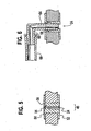
- FIG. 5 is a section through FIG. 1 at section line 5-5. This shows that the first partial hole 24 in the bottom face 52 of an end pad 14 aligns with a second partial hole 54 in the top face 56, shown in FIG 2 , of the end pad 14.
- the two partial holes 24 and 54 are separated by a diaphragm 58, and may preferably be positioned within one of the bores 46 in the end stiffeners 26 and 30.
- FIG. 6 is a section view of a barbed tubing coupling 64 inserted into a vacuum cup 10.
- a barbed coupling 64 of suitable size can be inserted into the second partial hole 54.
- the barbed coupling 64 preferably carrying a single barb on each end as shown, preferably passes through the pierced diaphragm 58 and uses the pierced diaphragm 58 as a locking element to retain the barbed coupling 64.
- Various options may be preferable in some applications, such as using multiple-barb ends on the barbed coupling 64 or passing the barbed coupling 64 through the pierced diaphragm 58 and the first partial hole 24, although preferably not extending the barbed coupling 64 so far through the bore 46 as to extend beyond the pin bottom end 20 and contact the workpiece 70.
- the top of the barbed tubing coupling 64 is shown to be set at a right angle 66.
- the right angle 66 shown may be preferable to allow a vacuum line 68 to deliver vacuum to the vacuum cup 10 without a sharp bend in the line 68.
- Other angles and other fitting styles may be preferable in some applications.
- the multiplicity of partial holes 24 in the end pads 14 can be used to provide optional vacuum connections.
- a pierced diaphragm 58 may leak substantially no air when no barbed coupling 64 has been installed in it. This can allow the vacuum cup 10 in which the pierced diaphragm 58 exists to hold vacuum acceptably. By extension, a vacuum cup 10 may remain usable with multiple diaphragms 58 that are unused but have been pierced.
- the standoff pins 18 are shown surrounded by the elastomer of the pads 14 and 16.
- the pin bottom ends 20 can be domed with a radius roughly equal to the elastic deformation of the workpiece 70 effected by the pressure stemming from the applied vacuum plus a portion of the weight of the rail-mounted drilling system. If the elastic deformation of the workpiece 70 can be shown to be negligible, then a satisfactory pin bottom end 20 shape may be achievable with a flat face square to the workpiece and a smooth edge roundoff.
- the pin bottom end 20 shape, radius of curvature, and size may preferably be chosen to at least minimize scuffing or marring of the workpiece 70.
- FIG, 7 is a side view with a partial cutaway, revealing the structure of a vacuum cup 10 pressed against a workpiece 70 and attached to a rail 72 with studs 74, nuts 76, and washers 78.
- the lip 12 is flexed upward from its rest position as a result of application of vacuum.
- a flat workpiece 70 is contacted by the standoff pins 18, causing the rail 72 to assume a flat shape, parallel to the workpiece 70.
- FIG. 8 is a section through the vacuum cup 10 of FIG. 1 , in which the kerfs 60 and upper groove 62 are shown as they would be with a vacuum cup 10 positioned on a flat workpiece 70.
- the standoff pins 18 shown in FIGS. 1 and 2
- This flexure allows the vacuum cup 10 to conform to a workpiece 70 with a relatively sharp curvature, and thus to cause the rail 72 to so conform. Twist in the workpiece 70 can be accommodated as well, with the elastomer flexing as necessary.
- FIG. 9 is a section through an alternative vacuum cup configuration retaining the upper groove 62 but without kerfs. This configuration may be preferable on some workpieces, for example where curvature is slight or nonexistent along the rail longitudinal axis.
- Alternative methods for fastening standoff pins to a rail could include welding, brazing, and equivalent metallurgical bonding methods, as well as application of a flange to the top of each standoff pin, which flange could have multiple radially-arrayed holes for rivets or other fastenings.
- the stud 74, nut 76, and washer 78 of the exemplary embodiment can be replaced by other threaded fasteners, such as screws with or without washers, and can be prevented from loosening by application of antivibration materials, upset threads, and other technologies.
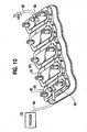
- FIG. 10 is an oblique view of a conformal vacuum cup 10 according to another design.
- the lip 12 is made wavy instead of straight-edged as in FIGS. 1-9 .
- the elastomeric material 80 does not surround the stiffeners 28 and 30 above an attachment shoulder 82.
- the embodiment shown has one inlet vacuum line 84 and one outlet vacuum line 86, with no provision for additional vacuum lines.
- a fitting 88 is employed to seal to a threaded hole and connect to a vacuum hose 94 at an approximate right angle.
- FIG. 10 further shows in schematic form the use of a vacuum source 92 connected by a vacuum hose 84 to use the vacuum cup 10.
- a second fitting 88 connects to a second vacuum hose 86 to carry vacuum to another vacuum cup 10 or to an accessory such as a gauge.
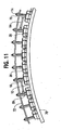
- FIG. 11 shows multiple samples of the conformal vacuum cup 10 of FIG. 10 attached to a curved rail 72 using studs 74, nuts 76, and washers 78. Also shown is a convex-curved workpiece 70. The curvature of the rail 72 requires the flexing of the conformal vacuum cups 10 to accommodate the drawing together of the individual stiffeners 30 and 48 shown in FIGS. 3 and 4 .
- the stiffeners 26, 28, 30, and 48 described herein can preferably be.fabricated from a material with specific physical properties.
- One such desirable stiffener property is higher flexure resistance than the rail 72 and/or the workpiece 70, particularly in the thickness used.
- Another such desirable stiffener property is compatibility with insertion of pins 18, which compatibility includes adequate malleability to permit pin 18 insertion and similarity in temperature coefficient of expansion to the pins 18.
- Another such desirable stiffener property is compatibility with the elastomeric overmolding material, which compatibility includes tolerance of the temperatures at which the molding takes place and chemical compatibility with the overmolding material.
- Typical materials likely to be suitable include various aluminum and stainless steel alloys, fiber reinforced phenolics, engineering plastics such as PEEK@, and others.
- Suitable elastomers for the vacuum cup overmolding material include a class of synthetic rubbers known generically as urethanes.
- Other classes of elastomers, such as vinyls, as well as other formable materials, may, like urethanes, have adequate ranges of durometer values and acceptable physical properties such as tear resistance for repeated use and may exhibit an ability to withstand rough treatment.
- Urethanes in the preferred range of durometers can in some formulations exhibit a desirable ability to cling to surfaces, which ability may add to the positioning force of the vacuum cups 10.
- Vinyls may exhibit significantly lower cling than urethanes, which may be preferable in some embodiments.
- Other elastomers may likewise exhibit desirable combinations of attributes for specific uses.
- Forcing air, such as from a compressor, through a vacuum cup system may allow the cups to function as air bearings to make tool repositioning easier and quicker.
- Specific features such as lip shape, interface surface profile, elastomer material choice, and available air flow rate may inhibit or facilitate such use.
Landscapes
- Engineering & Computer Science (AREA)
- Mechanical Engineering (AREA)
- Aviation & Aerospace Engineering (AREA)
- Manipulator (AREA)
- Pressure Vessels And Lids Thereof (AREA)
- Drilling And Boring (AREA)
- Automatic Assembly (AREA)
- Jigs For Machine Tools (AREA)
- Blow-Moulding Or Thermoforming Of Plastics Or The Like (AREA)
- Hooks, Suction Cups, And Attachment By Adhesive Means (AREA)
- Insertion Pins And Rivets (AREA)
- Coating With Molten Metal (AREA)
- Advancing Webs (AREA)
- Connection Of Plates (AREA)
- Auxiliary Devices For Machine Tools (AREA)
Claims (15)
- Bearbeitungsvorrichtung mit biegbarer Führungsbahn, die aufweist:eine Schiene (72), die an eine schienenseitige Oberfläche eines Werkstücks anpassbar ist,ein Vakuumnapf (10) für eine lösbare Verbindung zwischen der Schiene (72) und der schienenseitigen Oberfläche eines Werkstücks (70), wobei der Vakuumnapf aufweist:eine innere Oberfläche des Vakuumnapfes,eine äußere Oberfläche des Vakuumnapfes,mehrere Glieder (14, 16), die ein elastisches Material aufweisen, wobei die Fläche zwischen einem jeden Glied undder schienenseitigen Oberfläche des Werkstücks eine Zone festlegt;mehrere Versteifungselemente (26, 28), wobei die Versteifungselemente an der Schiene anbringbar sind, undein an der Schiene geführtes Werkzeug,wobei die Bearbeitungsvorrichtung mit biegbarer Führungsbahn dadurch gekennzeichnet ist, dass
die mehreren Glieder (14, 16) zu einem zusammenhängenden Ganzen gefügt sind,
der Vakuumnapf eine den mehreren Gliedern entsprechende Anordnung von Zonen umfasst,
zumindest eines der mehreren Versteifungselemente (26, 28) innerhalb eines jeweils zugehörigen der Glieder (14, 16) zumindest teilweise eingebettet ist, und dadurch, dass der Vakuumnapf ferner aufweist:einen elastische Dichtungsrand, der mit den Gliedern (14, 16) verbunden ist und den Rand der Anordnung von Zonen umgibt. - Bearbeitungsvorrichtung mit biegbarer Führungsbahn nach Anspruch 1, die ferner aufweist:eine Nut (62) zwischen einander benachbarten Gliedern, wobei die Nut (62) ein flexibles Gelenk zwischen einander benachbarten Versteifungen ausbildet.
- Bearbeitungsvorrichtung mit biegbarer Führungsbahn nach Anspruch 2, die ferner aufweist:eine Kerbe (60), die zwischen dem Glied und der Nut (62) einen Schlitz aufweist.
- Bearbeitungsvorrichtung mit biegbarer Führungsbahn nach Anspruch 3, worin sich die Nut (62) von der äußeren Oberfläche des Vakuumnapfes in das Volumen des elastischen Materials erstreckt und wobei sich die Kerbe (60) von der inneren Oberfläche des Vakuumnapfes in das Volumen des elastischen Materials erstreckt.
- Bearbeitungsvorrichtung mit biegbarer Führungsbahn nach Anspruch 1, die ferner aufweist:eine Vakuumkammer, die ein Volumen einnimmt, das zwischen der inneren Oberfläche des Vakuumnapfes und dem Werkstück (70) definiert ist, wobei die Vakuumkammer die Zonen der Anordnung verbindet, undeinen Einlassanschluss, der den Vakuumnapf durchdringt unddurch den ein Fluid aus der Vakuumkammer entnommen oderin diese injiziert werden kann.
- Bearbeitungsvorrichtung mit biegbarer Führungsbahn nach Anspruch 1, worin die mehreren Glieder ferner ein erstes Endglied (14) und ein zweites Endglied (14) aufweisen.
- Bearbeitungsvorrichtung mit biegbarer Führungsbahn nach Anspruch 6, worin in dem ersten Endglied (14) zumindest ein Durchgangsloch (24) ausgebildet ist.
- Bearbeitungsvorrichtung mit biegbarer Führungsbahn nach Anspruch 6, worin die mehreren Glieder ferner aufweisen:ein Zwischenglied (16), das zwischen dem ersten Endglied (14) und dem zweiten Endglied (14) angeordnet ist.
- Bearbeitungsvorrichtung mit biegbarer Führungsbahn nach Anspruch 1, worin der Dichtungsrand ferner aufweist:eine Kontaktlippe (12), wobei die Kontaktlippe so ausgebildet ist,dass sie das Werkstück (70) beim Anlegen durchgehend berührt und wobei die Kontaktlippe die mehreren Glieder (14, 16) umgibt.
- Bearbeitungsvorrichtung mit biegbarer Führungsbahn nach Anspruch 1, die ferner aufweist:eine zwischen der Schiene (72) und der schienenseitigen Oberfläche des Werkstücks (70) wirkende Befestigungskraft, die aus einem Anlegen eines Vakuums an den Vakuumnapf (10) resultiert, während die Kontaktlippe (12) einen stetigen Kontakt zwischen der Schiene (72) und der schienenseitigen Oberfläche des Werkstücks (70) herstellt.
- Bearbeitungsvorrichtung mit biegbarer Führungsbahn nach Anspruch 1, die ferner aufweist:einen Auslassanschluss zum Ermöglichen einer Fluidverbindung zwischen einem Vakuumerzeuger und der Anordnung von Zonen.
- Bearbeitungsvorrichtung mit biegbarer Führungsbahn nach Anspruch 1, die ferner aufweist:einen Vakuumnapfverbinder (64, 88) zum Herstellen einer Fluidverbindung zwischen dem Vakuumnapf und einem zweiten Vakuumnapf.
- Bearbeitungsvorrichtung mit biegbarer Führungsbahn nach Anspruch 1, worin das elastische Material Urethan umfasst.
- Bearbeitungsvorrichtung mit biegbarer Führungsbahn nach Anspruch 1, die ferner aufweist:mehrere an der Schiene angebrachte Abstandsbolzen (18), wobei zumindest einer der Abstandsbolzen (18) an einem zugehörigen Versteifungselement (26, 28) angebracht ist.
- Bearbeitungsvorrichtung mit biegbarer Führungsbahn nach Anspruch 14, worin zumindest ein Ende eines jeden der mehreren Abstandsbolzen (18) durch den Dichtungsrand geführt ist.
Applications Claiming Priority (2)
| Application Number | Priority Date | Filing Date | Title |
|---|---|---|---|
| US10/854,209 US7134649B2 (en) | 2004-05-27 | 2004-05-27 | Conformal vacuum cup apparatus and method |
| EP05848361A EP1755829B1 (de) | 2004-05-27 | 2005-05-09 | Konformes saugnapfgerät zur abnehmbaren befestigung einer leiste auf einer werkstückoberfläche |
Related Parent Applications (2)
| Application Number | Title | Priority Date | Filing Date |
|---|---|---|---|
| EP05848361.1 Division | 2005-05-09 | ||
| EP05848361A Division EP1755829B1 (de) | 2004-05-27 | 2005-05-09 | Konformes saugnapfgerät zur abnehmbaren befestigung einer leiste auf einer werkstückoberfläche |
Publications (3)
| Publication Number | Publication Date |
|---|---|
| EP2082839A2 EP2082839A2 (de) | 2009-07-29 |
| EP2082839A3 EP2082839A3 (de) | 2012-12-19 |
| EP2082839B1 true EP2082839B1 (de) | 2015-08-19 |
Family
ID=35424298
Family Applications (3)
| Application Number | Title | Priority Date | Filing Date |
|---|---|---|---|
| EP05848361A Expired - Lifetime EP1755829B1 (de) | 2004-05-27 | 2005-05-09 | Konformes saugnapfgerät zur abnehmbaren befestigung einer leiste auf einer werkstückoberfläche |
| EP09005809.0A Expired - Lifetime EP2082839B1 (de) | 2004-05-27 | 2005-05-09 | Konformes Saugnapfgerät und entsprechendes Verfahren |
| EP09005808.2A Expired - Lifetime EP2082838B1 (de) | 2004-05-27 | 2005-05-09 | Konformes Saugnapfgerät und entsprechendes Verfahren |
Family Applications Before (1)
| Application Number | Title | Priority Date | Filing Date |
|---|---|---|---|
| EP05848361A Expired - Lifetime EP1755829B1 (de) | 2004-05-27 | 2005-05-09 | Konformes saugnapfgerät zur abnehmbaren befestigung einer leiste auf einer werkstückoberfläche |
Family Applications After (1)
| Application Number | Title | Priority Date | Filing Date |
|---|---|---|---|
| EP09005808.2A Expired - Lifetime EP2082838B1 (de) | 2004-05-27 | 2005-05-09 | Konformes Saugnapfgerät und entsprechendes Verfahren |
Country Status (10)
| Country | Link |
|---|---|
| US (3) | US7134649B2 (de) |
| EP (3) | EP1755829B1 (de) |
| JP (2) | JP4749419B2 (de) |
| KR (1) | KR101179017B1 (de) |
| CN (1) | CN100445039C (de) |
| AT (1) | ATE439947T1 (de) |
| CA (1) | CA2567780C (de) |
| DE (1) | DE602005016106D1 (de) |
| ES (3) | ES2330129T3 (de) |
| WO (1) | WO2006043983A2 (de) |
Families Citing this family (60)
| Publication number | Priority date | Publication date | Assignee | Title |
|---|---|---|---|---|
| US7134649B2 (en) * | 2004-05-27 | 2006-11-14 | The Boeing Company | Conformal vacuum cup apparatus and method |
| US7966713B2 (en) * | 2006-05-17 | 2011-06-28 | The Boeing Company | Tooling head mounted structural positioning |
| US7677181B2 (en) * | 2006-11-06 | 2010-03-16 | The Boeing Company | Interlocking precision flexible rail system |
| US7611314B2 (en) * | 2007-08-01 | 2009-11-03 | The Boeing Company | Aligning a machine tool with a target location on a structure |
| WO2009105579A2 (en) | 2008-02-19 | 2009-08-27 | Garahan Patrick J | Portable holder for beverage containers |
| US7922272B2 (en) * | 2008-04-11 | 2011-04-12 | The Boeing Company | Method for application and accurate positioning of graphics on a surface |
| US20100037444A1 (en) | 2008-08-15 | 2010-02-18 | Reid Eric M | Reconfigurable flexible rail apparatus and method |
| US20100180711A1 (en) | 2009-01-19 | 2010-07-22 | Comau, Inc. | Robotic end effector system and method |
| DE102009044305A1 (de) * | 2009-10-21 | 2011-05-05 | Fooke Gmbh | Verfahren zum Halten und Bearbeiten eines Werkstückes mit Spannplatte, sowie Vorrichtung zum Aussteifen eines Werkstückes mit Spannplatte |
| US8503610B1 (en) | 2010-11-23 | 2013-08-06 | The Boeing Company | X-ray inspection tool |
| CN102060100B (zh) * | 2010-12-14 | 2013-03-27 | 钱智声 | 飞机机身-机翼连接机构 |
| DE102011106214A1 (de) * | 2011-06-07 | 2012-12-13 | Brötje-Automation GmbH | Endeffektor |
| US8588262B1 (en) | 2011-09-07 | 2013-11-19 | The Boeing Company | Quantum dot detection |
| US8960745B2 (en) * | 2011-11-18 | 2015-02-24 | Nike, Inc | Zoned activation manufacturing vacuum tool |
| US8858744B2 (en) | 2011-11-18 | 2014-10-14 | Nike, Inc. | Multi-functional manufacturing tool |
| US8849620B2 (en) | 2011-11-18 | 2014-09-30 | Nike, Inc. | Automated 3-D modeling of shoe parts |
| US9010827B2 (en) | 2011-11-18 | 2015-04-21 | Nike, Inc. | Switchable plate manufacturing vacuum tool |
| CN102847979A (zh) * | 2012-03-21 | 2013-01-02 | 北京航空航天大学 | 一种吸附于飞机表面用于运载制孔末端执行器的柔性轨道 |
| DE102012208148A1 (de) * | 2012-05-15 | 2013-11-21 | Lufthansa Technical Training GmbH | Schablone zur Bearbeitung von Großbauteilen im Flugzeugbau |
| CN102765088B (zh) * | 2012-07-16 | 2015-12-02 | 上海飞机制造有限公司 | 单侧柔性吸附式自动钻孔机器人 |
| US9302787B2 (en) * | 2012-09-14 | 2016-04-05 | The Boeing Company | Vacuum adhering apparatus for automated maintenance of airfoil-shaped bodies |
| US9475527B2 (en) | 2012-10-30 | 2016-10-25 | The Boeing Company | Autonomous crawling assembly system |
| US9327376B2 (en) * | 2012-10-30 | 2016-05-03 | The Boeing Company | Dual function movement component for automated assembly systems |
| US10065280B2 (en) | 2012-10-30 | 2018-09-04 | The Boeing Company | Multifunction legs for autonomous crawling assembly equipment |
| US20140272312A1 (en) * | 2013-03-13 | 2014-09-18 | Gulfstream Aerospace Corporation | Aircraft component and method of making an aircraft component |
| US9211679B1 (en) | 2013-05-03 | 2015-12-15 | The Boeing Company | Systems and methods of forming a skin for a composite structure and composite structures including the same |
| US9745815B2 (en) * | 2013-10-10 | 2017-08-29 | Newpark Mats & Integrated Services Llc | Apparatus and methods for sealing around the opening to a cellar formed around a hydrocarbon exploration or production well |
| US9511548B1 (en) | 2013-10-16 | 2016-12-06 | The Boeing Company | Systems and methods for assembling a skin of a composite structure |
| CN103955165A (zh) * | 2014-04-11 | 2014-07-30 | 浙江大学 | 通过反解环形轨道制孔系统运动学方程获得关节变量的方法 |
| CN104443426B (zh) * | 2014-10-08 | 2016-06-08 | 中国航空工业集团公司北京航空制造工程研究所 | 一种飞机钛合金框梁类零件制造方法 |
| US9663247B2 (en) | 2015-02-27 | 2017-05-30 | The Boeing Company | Systems, methods, and vacuum chucks for transferring flexible elongate bodies |
| US9823160B2 (en) * | 2015-04-02 | 2017-11-21 | The Boeing Company | Apparatus and methods for testing suction cups mounted to a track |
| DE102015009177A1 (de) | 2015-07-09 | 2017-01-12 | Broetje-Automation Gmbh | Verfahren zum Herstellen eines Faser-Metall-Laminatbauteils eines Flugzeugs |
| JP6367158B2 (ja) | 2015-07-13 | 2018-08-01 | 三菱重工業株式会社 | 吸着装置、把持装置および搬送方法 |
| US10005234B2 (en) | 2015-10-29 | 2018-06-26 | The Boeing Company | Devices, systems, and methods for compacting a charge of composite material across an edge |
| GB2543843B (en) * | 2015-10-31 | 2020-04-29 | Loop Tech Ltd | A system for handling flexible materials |
| CN105234866A (zh) * | 2015-11-17 | 2016-01-13 | 江苏保捷锻压有限公司 | 一种汽车变速箱齿轮多点定位装置 |
| EP3228428A1 (de) * | 2016-04-05 | 2017-10-11 | KEURO Besitz GmbH & Co. EDV-Dienstleistungs KG | Sauggreifer für eine handhabungsvorrichtung |
| US10479510B2 (en) | 2016-10-12 | 2019-11-19 | The Boeing Company | Modular environmental control chamber |
| FR3061054B1 (fr) * | 2016-12-22 | 2019-06-14 | Airbus Operations | Dispositif de guidage adapte pour se positionner sur une surface a double rayon de courbure |
| US10099385B2 (en) * | 2017-02-06 | 2018-10-16 | The Boeing Company | End effectors carrying plies of material for shaping by a mandrel |
| CN108453642B (zh) * | 2017-02-20 | 2021-08-13 | 波音公司 | 与面板一起使用的工具组件及通过工具组件支撑面板的方法 |
| US10906157B2 (en) | 2017-02-20 | 2021-02-02 | The Boeing Company | Modular tooling fixture with interchangeable panel defining a tooling surface |
| CN107515088B (zh) * | 2017-08-04 | 2019-06-28 | 中国航空工业集团公司西安飞机设计研究所 | 一种金属机翼主盒段弯曲刚度测试的模型试验件设计方法 |
| US10369706B2 (en) | 2017-08-09 | 2019-08-06 | The Boeing Company | End effectors carrying plies of limp material for shaping by a mandrel |
| US11041518B2 (en) * | 2018-07-19 | 2021-06-22 | The Boeing Company | Methods for bonding a structural component within a channel of a rail |
| US10807383B2 (en) | 2018-09-24 | 2020-10-20 | The Boeing Company | Robotic printing system for an aircraft exterior |
| CN109552663B (zh) * | 2018-11-22 | 2021-05-04 | 南京航空航天大学 | 一种柔性定位器以及应用其装配复合材料翼盒的方法 |
| CN109552881A (zh) * | 2018-12-04 | 2019-04-02 | 武汉华星光电技术有限公司 | 一种显示面板真空吸取系统 |
| CN112405570A (zh) * | 2019-08-21 | 2021-02-26 | 牧今科技 | 用于夹持和保持物体的机器人多夹持器组件和方法 |
| US11345029B2 (en) | 2019-08-21 | 2022-05-31 | Mujin, Inc. | Robotic multi-gripper assemblies and methods for gripping and holding objects |
| CN111085954A (zh) * | 2019-12-24 | 2020-05-01 | 深圳市华星光电半导体显示技术有限公司 | 基板吸附装置 |
| US12304062B2 (en) * | 2021-01-04 | 2025-05-20 | The Boeing Company | Part transfer system |
| US11920915B2 (en) | 2021-04-07 | 2024-03-05 | The Boeing Company | Non-contact measurement for interface gaps |
| CN113478250B (zh) * | 2021-05-25 | 2022-06-14 | 成都飞机工业(集团)有限责任公司 | 一种大型可重组式双曲面修切夹具及其组装方法 |
| FR3125976B1 (fr) * | 2021-08-06 | 2023-08-11 | Joulin Cemma | Tête de préhension par aspiration, module élémentaire et châssis associé |
| CN116252149A (zh) * | 2022-09-08 | 2023-06-13 | 膳魔师(江苏)家庭制品有限公司 | 一种轮径压切一体装置 |
| US20240140733A1 (en) * | 2022-11-01 | 2024-05-02 | Aptera Motors Corp. | Pick flat place curved assembly tool, system and method |
| EP4530032A1 (de) * | 2023-09-28 | 2025-04-02 | CUSTOMCELLS Holding GmbH | Vakuumgreifer und verfahren zum aufnehmen eines flächigen werkstücks sowie stapelvorrichtung zum aufnehmen einer elektrode |
| KR102907178B1 (ko) * | 2023-11-24 | 2026-01-02 | 이재신 | 항공기 스킨 제조 시스템 |
Family Cites Families (34)
| Publication number | Priority date | Publication date | Assignee | Title |
|---|---|---|---|---|
| US2946246A (en) * | 1957-09-20 | 1960-07-26 | Gen Motors Corp | Drill fixture |
| US2910895A (en) * | 1957-12-13 | 1959-11-03 | James C Winslow | Power tool with suction foot |
| US3591228A (en) * | 1968-06-17 | 1971-07-06 | David John Tudor Webb | Suction pads |
| US3575364A (en) * | 1968-07-22 | 1971-04-20 | Gen Dynamics Corp | Flexible track |
| JPS4947785B1 (de) * | 1970-05-12 | 1974-12-18 | ||
| JPS5228183B2 (de) * | 1973-05-07 | 1977-07-25 | ||
| DE3390058C2 (de) * | 1982-07-02 | 1987-10-01 | Rolf Rasmussen | An einem Gabelstapler vorgesehene Unterdruck-Greif-und Halteeinrichtung f}r eine Papierrolle |
| JPS63119581A (ja) * | 1986-11-07 | 1988-05-24 | Fujitsu Ltd | 半導体記憶装置 |
| JPH0435342Y2 (de) * | 1987-01-27 | 1992-08-21 | ||
| JPS6462275A (en) * | 1987-09-02 | 1989-03-08 | Ural Politekhn Inst | Method of repairing surface of steel part |
| JPH0544375Y2 (de) * | 1987-10-12 | 1993-11-10 | ||
| JPH01137934A (ja) * | 1987-11-19 | 1989-05-30 | Nippon Oil & Fats Co Ltd | 煮干し用酸化防止製剤 |
| JPH01137934U (de) * | 1988-03-11 | 1989-09-20 | ||
| JPH0812230B2 (ja) * | 1988-09-06 | 1996-02-07 | 株式会社日立製作所 | Ic試験装置 |
| JPH072540Y2 (ja) * | 1988-11-16 | 1995-01-25 | セントラル硝子株式会社 | 吸着具 |
| JPH0724188Y2 (ja) * | 1990-07-03 | 1995-06-05 | 功 庄田 | 端面加工用吸着テーブル |
| US5457868A (en) * | 1991-03-26 | 1995-10-17 | Gfm Gesellschaft Fur Fertigungstechnik Und Maschinenbau Aktiengesellschaft | Work supporting method using a deck for use in machine tools, particularly in cutting machines |
| DE4203808A1 (de) | 1992-02-10 | 1993-08-12 | Bruno Gruber | Anschlag- bzw. anleg- und fuehrungseinrichtung |
| ATE174835T1 (de) * | 1992-05-06 | 1999-01-15 | Carne James Christopher | Vakuumplatte |
| DE4433925A1 (de) * | 1994-09-23 | 1996-03-28 | Schlick Heinrich Gmbh Co Kg | Vorrichtung für eine Oberflächenbehandlung ausgedehnter, vorzugsweise gewölbter Oberflächen, insbesondere der Rumpfaußenflächen von Schiffen und Flugzeugen |
| US5704599A (en) * | 1996-01-18 | 1998-01-06 | Slothower; Stephen G. | Vacuum apparatus for aligning and securely positioning components |
| JP3252752B2 (ja) * | 1997-05-21 | 2002-02-04 | 日本鋼管株式会社 | 板体の運搬吊具 |
| US5865827A (en) * | 1997-06-03 | 1999-02-02 | Bullister; Edward T | Vacuum device for securing human tissue |
| US6158666A (en) * | 1997-11-26 | 2000-12-12 | Banks; David P. | Vacuum fastened guide and method for supporting tooling on a component |
| JP3230152B2 (ja) * | 1997-12-26 | 2001-11-19 | 日本鋼管株式会社 | サンプリング板採取装置 |
| IT1299177B1 (it) * | 1998-05-20 | 2000-02-29 | Quintilio Lupi | Sistema per la lavorazionme a contorno con maschera di lastre di marmo, pietra, vetro o simili |
| US6467385B1 (en) * | 1999-12-03 | 2002-10-22 | The Boeing Company | Panel trimming system |
| US6655671B2 (en) * | 2000-08-04 | 2003-12-02 | Fuji Machine Mfg. Co., Ltd. | Printed-wiring-board holding apparatus |
| US6413022B1 (en) * | 2000-09-18 | 2002-07-02 | The Boeing Company | Vacuum clamp device |
| JP2002187085A (ja) * | 2000-12-19 | 2002-07-02 | Myotoku Ltd | 吸着パッド及び被吸着物の吸着方法 |
| US6843328B2 (en) * | 2001-12-10 | 2005-01-18 | The Boeing Company | Flexible track drilling machine |
| CN1296261C (zh) * | 2002-06-22 | 2007-01-24 | 鸿富锦精密工业(深圳)有限公司 | 真空夹具及其使用方法 |
| US6772508B2 (en) * | 2002-07-24 | 2004-08-10 | The Boeing Company | Fastener delivery and installation system |
| US7134649B2 (en) * | 2004-05-27 | 2006-11-14 | The Boeing Company | Conformal vacuum cup apparatus and method |
-
2004
- 2004-05-27 US US10/854,209 patent/US7134649B2/en not_active Expired - Lifetime
-
2005
- 2005-05-09 CA CA2567780A patent/CA2567780C/en not_active Expired - Lifetime
- 2005-05-09 KR KR1020067027433A patent/KR101179017B1/ko not_active Expired - Lifetime
- 2005-05-09 CN CNB2005800255654A patent/CN100445039C/zh not_active Expired - Lifetime
- 2005-05-09 JP JP2007515126A patent/JP4749419B2/ja not_active Expired - Lifetime
- 2005-05-09 EP EP05848361A patent/EP1755829B1/de not_active Expired - Lifetime
- 2005-05-09 AT AT05848361T patent/ATE439947T1/de not_active IP Right Cessation
- 2005-05-09 ES ES05848361T patent/ES2330129T3/es not_active Expired - Lifetime
- 2005-05-09 ES ES09005809.0T patent/ES2546210T3/es not_active Expired - Lifetime
- 2005-05-09 EP EP09005809.0A patent/EP2082839B1/de not_active Expired - Lifetime
- 2005-05-09 ES ES09005808.2T patent/ES2562921T3/es not_active Expired - Lifetime
- 2005-05-09 DE DE602005016106T patent/DE602005016106D1/de not_active Expired - Lifetime
- 2005-05-09 EP EP09005808.2A patent/EP2082838B1/de not_active Expired - Lifetime
- 2005-05-09 WO PCT/US2005/016085 patent/WO2006043983A2/en not_active Ceased
-
2006
- 2006-08-18 US US11/505,951 patent/US7526851B1/en not_active Expired - Lifetime
- 2006-08-18 US US11/505,952 patent/US7380776B2/en not_active Expired - Lifetime
-
2011
- 2011-03-11 JP JP2011054047A patent/JP5265718B2/ja not_active Expired - Lifetime
Also Published As
| Publication number | Publication date |
|---|---|
| ATE439947T1 (de) | 2009-09-15 |
| CA2567780A1 (en) | 2006-04-27 |
| JP2008501538A (ja) | 2008-01-24 |
| US7134649B2 (en) | 2006-11-14 |
| CN1993208A (zh) | 2007-07-04 |
| EP2082838A2 (de) | 2009-07-29 |
| US7380776B2 (en) | 2008-06-03 |
| JP5265718B2 (ja) | 2013-08-14 |
| ES2562921T3 (es) | 2016-03-09 |
| US7526851B1 (en) | 2009-05-05 |
| DE602005016106D1 (de) | 2009-10-01 |
| ES2330129T3 (es) | 2009-12-04 |
| EP2082838B1 (de) | 2016-02-10 |
| US20060277733A1 (en) | 2006-12-14 |
| EP2082839A3 (de) | 2012-12-19 |
| CA2567780C (en) | 2012-12-11 |
| JP4749419B2 (ja) | 2011-08-17 |
| ES2546210T3 (es) | 2015-09-21 |
| KR20070020088A (ko) | 2007-02-16 |
| EP2082839A2 (de) | 2009-07-29 |
| WO2006043983A2 (en) | 2006-04-27 |
| WO2006043983A3 (en) | 2006-07-20 |
| JP2011167841A (ja) | 2011-09-01 |
| US20090133261A1 (en) | 2009-05-28 |
| CN100445039C (zh) | 2008-12-24 |
| US20050263949A1 (en) | 2005-12-01 |
| KR101179017B1 (ko) | 2012-09-03 |
| EP1755829B1 (de) | 2009-08-19 |
| EP2082838A3 (de) | 2013-02-20 |
| EP1755829A1 (de) | 2007-02-28 |
Similar Documents
| Publication | Publication Date | Title |
|---|---|---|
| EP2082839B1 (de) | Konformes Saugnapfgerät und entsprechendes Verfahren | |
| US10906157B2 (en) | Modular tooling fixture with interchangeable panel defining a tooling surface | |
| EP1563950B1 (de) | Bohrmaschine mit flexiblen Führungen | |
| US9399510B2 (en) | Hat stringer closeout fitting and method of making same | |
| EP3363588B1 (de) | Modulare werkzeughalterung mit austauschbarer platte zur definition einer werkzeugoberfläche | |
| GB2586034A (en) | Floating nut assembly | |
| EP3378781A1 (de) | Rauchdichter sockensammler/-schachtel | |
| US20090283640A1 (en) | Attachment system and method | |
| JP7000304B2 (ja) | ロボットのシール構造およびロボット | |
| US10632596B2 (en) | Apparatus for binding to a surface and method of use thereof | |
| EP3730747B1 (de) | Verbinden von komponenten | |
| JP6788262B2 (ja) | ダイヤフラム、およびダイヤフラムを使用した流体制御機器 | |
| EP3862172B1 (de) | Verbundplattewerkzeugsystem und verfahren | |
| KR102348133B1 (ko) | 밀봉 가스켓 | |
| US7677542B2 (en) | Vacuum-mounted clamp | |
| JPH02311216A (ja) | エキスパンデイング工具 |
Legal Events
| Date | Code | Title | Description |
|---|---|---|---|
| PUAI | Public reference made under article 153(3) epc to a published international application that has entered the european phase |
Free format text: ORIGINAL CODE: 0009012 |
|
| 17P | Request for examination filed |
Effective date: 20090427 |
|
| AC | Divisional application: reference to earlier application |
Ref document number: 1755829 Country of ref document: EP Kind code of ref document: P |
|
| AK | Designated contracting states |
Kind code of ref document: A2 Designated state(s): AT BE BG CH CY CZ DE DK EE ES FI FR GB GR HU IE IS IT LI LT LU MC NL PL PT RO SE SI SK TR |
|
| PUAL | Search report despatched |
Free format text: ORIGINAL CODE: 0009013 |
|
| AK | Designated contracting states |
Kind code of ref document: A3 Designated state(s): AT BE BG CH CY CZ DE DK EE ES FI FR GB GR HU IE IS IT LI LT LU MC NL PL PT RO SE SI SK TR |
|
| RIC1 | Information provided on ipc code assigned before grant |
Ipc: B25B 11/00 20060101AFI20121115BHEP |
|
| 17Q | First examination report despatched |
Effective date: 20140102 |
|
| GRAP | Despatch of communication of intention to grant a patent |
Free format text: ORIGINAL CODE: EPIDOSNIGR1 |
|
| INTG | Intention to grant announced |
Effective date: 20150107 |
|
| GRAP | Despatch of communication of intention to grant a patent |
Free format text: ORIGINAL CODE: EPIDOSNIGR1 |
|
| INTG | Intention to grant announced |
Effective date: 20150306 |
|
| GRAS | Grant fee paid |
Free format text: ORIGINAL CODE: EPIDOSNIGR3 |
|
| GRAA | (expected) grant |
Free format text: ORIGINAL CODE: 0009210 |
|
| AC | Divisional application: reference to earlier application |
Ref document number: 1755829 Country of ref document: EP Kind code of ref document: P |
|
| AK | Designated contracting states |
Kind code of ref document: B1 Designated state(s): AT BE BG CH CY CZ DE DK EE ES FI FR GB GR HU IE IS IT LI LT LU MC NL PL PT RO SE SI SK TR |
|
| REG | Reference to a national code |
Ref country code: GB Ref legal event code: FG4D |
|
| REG | Reference to a national code |
Ref country code: CH Ref legal event code: EP |
|
| REG | Reference to a national code |
Ref country code: IE Ref legal event code: FG4D |
|
| REG | Reference to a national code |
Ref country code: AT Ref legal event code: REF Ref document number: 743450 Country of ref document: AT Kind code of ref document: T Effective date: 20150915 |
|
| REG | Reference to a national code |
Ref country code: ES Ref legal event code: FG2A Ref document number: 2546210 Country of ref document: ES Kind code of ref document: T3 Effective date: 20150921 |
|
| REG | Reference to a national code |
Ref country code: DE Ref legal event code: R096 Ref document number: 602005047309 Country of ref document: DE |
|
| REG | Reference to a national code |
Ref country code: AT Ref legal event code: MK05 Ref document number: 743450 Country of ref document: AT Kind code of ref document: T Effective date: 20150819 |
|
| REG | Reference to a national code |
Ref country code: LT Ref legal event code: MG4D |
|
| REG | Reference to a national code |
Ref country code: NL Ref legal event code: MP Effective date: 20150819 |
|
| PG25 | Lapsed in a contracting state [announced via postgrant information from national office to epo] |
Ref country code: LT Free format text: LAPSE BECAUSE OF FAILURE TO SUBMIT A TRANSLATION OF THE DESCRIPTION OR TO PAY THE FEE WITHIN THE PRESCRIBED TIME-LIMIT Effective date: 20150819 Ref country code: FI Free format text: LAPSE BECAUSE OF FAILURE TO SUBMIT A TRANSLATION OF THE DESCRIPTION OR TO PAY THE FEE WITHIN THE PRESCRIBED TIME-LIMIT Effective date: 20150819 Ref country code: GR Free format text: LAPSE BECAUSE OF FAILURE TO SUBMIT A TRANSLATION OF THE DESCRIPTION OR TO PAY THE FEE WITHIN THE PRESCRIBED TIME-LIMIT Effective date: 20151120 |
|
| PG25 | Lapsed in a contracting state [announced via postgrant information from national office to epo] |
Ref country code: IS Free format text: LAPSE BECAUSE OF FAILURE TO SUBMIT A TRANSLATION OF THE DESCRIPTION OR TO PAY THE FEE WITHIN THE PRESCRIBED TIME-LIMIT Effective date: 20151219 Ref country code: AT Free format text: LAPSE BECAUSE OF FAILURE TO SUBMIT A TRANSLATION OF THE DESCRIPTION OR TO PAY THE FEE WITHIN THE PRESCRIBED TIME-LIMIT Effective date: 20150819 Ref country code: SE Free format text: LAPSE BECAUSE OF FAILURE TO SUBMIT A TRANSLATION OF THE DESCRIPTION OR TO PAY THE FEE WITHIN THE PRESCRIBED TIME-LIMIT Effective date: 20150819 Ref country code: PT Free format text: LAPSE BECAUSE OF FAILURE TO SUBMIT A TRANSLATION OF THE DESCRIPTION OR TO PAY THE FEE WITHIN THE PRESCRIBED TIME-LIMIT Effective date: 20151221 Ref country code: PL Free format text: LAPSE BECAUSE OF FAILURE TO SUBMIT A TRANSLATION OF THE DESCRIPTION OR TO PAY THE FEE WITHIN THE PRESCRIBED TIME-LIMIT Effective date: 20150819 |
|
| PG25 | Lapsed in a contracting state [announced via postgrant information from national office to epo] |
Ref country code: NL Free format text: LAPSE BECAUSE OF FAILURE TO SUBMIT A TRANSLATION OF THE DESCRIPTION OR TO PAY THE FEE WITHIN THE PRESCRIBED TIME-LIMIT Effective date: 20150819 |
|
| PG25 | Lapsed in a contracting state [announced via postgrant information from national office to epo] |
Ref country code: DK Free format text: LAPSE BECAUSE OF FAILURE TO SUBMIT A TRANSLATION OF THE DESCRIPTION OR TO PAY THE FEE WITHIN THE PRESCRIBED TIME-LIMIT Effective date: 20150819 Ref country code: EE Free format text: LAPSE BECAUSE OF FAILURE TO SUBMIT A TRANSLATION OF THE DESCRIPTION OR TO PAY THE FEE WITHIN THE PRESCRIBED TIME-LIMIT Effective date: 20150819 Ref country code: CZ Free format text: LAPSE BECAUSE OF FAILURE TO SUBMIT A TRANSLATION OF THE DESCRIPTION OR TO PAY THE FEE WITHIN THE PRESCRIBED TIME-LIMIT Effective date: 20150819 Ref country code: SK Free format text: LAPSE BECAUSE OF FAILURE TO SUBMIT A TRANSLATION OF THE DESCRIPTION OR TO PAY THE FEE WITHIN THE PRESCRIBED TIME-LIMIT Effective date: 20150819 |
|
| REG | Reference to a national code |
Ref country code: DE Ref legal event code: R097 Ref document number: 602005047309 Country of ref document: DE |
|
| REG | Reference to a national code |
Ref country code: FR Ref legal event code: PLFP Year of fee payment: 12 |
|
| PG25 | Lapsed in a contracting state [announced via postgrant information from national office to epo] |
Ref country code: RO Free format text: LAPSE BECAUSE OF FAILURE TO SUBMIT A TRANSLATION OF THE DESCRIPTION OR TO PAY THE FEE WITHIN THE PRESCRIBED TIME-LIMIT Effective date: 20150819 |
|
| PLBE | No opposition filed within time limit |
Free format text: ORIGINAL CODE: 0009261 |
|
| STAA | Information on the status of an ep patent application or granted ep patent |
Free format text: STATUS: NO OPPOSITION FILED WITHIN TIME LIMIT |
|
| 26N | No opposition filed |
Effective date: 20160520 |
|
| PG25 | Lapsed in a contracting state [announced via postgrant information from national office to epo] |
Ref country code: SI Free format text: LAPSE BECAUSE OF FAILURE TO SUBMIT A TRANSLATION OF THE DESCRIPTION OR TO PAY THE FEE WITHIN THE PRESCRIBED TIME-LIMIT Effective date: 20150819 Ref country code: BE Free format text: LAPSE BECAUSE OF NON-PAYMENT OF DUE FEES Effective date: 20160531 |
|
| PG25 | Lapsed in a contracting state [announced via postgrant information from national office to epo] |
Ref country code: LU Free format text: LAPSE BECAUSE OF FAILURE TO SUBMIT A TRANSLATION OF THE DESCRIPTION OR TO PAY THE FEE WITHIN THE PRESCRIBED TIME-LIMIT Effective date: 20160509 Ref country code: BE Free format text: LAPSE BECAUSE OF FAILURE TO SUBMIT A TRANSLATION OF THE DESCRIPTION OR TO PAY THE FEE WITHIN THE PRESCRIBED TIME-LIMIT Effective date: 20150819 |
|
| REG | Reference to a national code |
Ref country code: CH Ref legal event code: PL |
|
| PG25 | Lapsed in a contracting state [announced via postgrant information from national office to epo] |
Ref country code: LI Free format text: LAPSE BECAUSE OF NON-PAYMENT OF DUE FEES Effective date: 20160531 Ref country code: CH Free format text: LAPSE BECAUSE OF NON-PAYMENT OF DUE FEES Effective date: 20160531 |
|
| REG | Reference to a national code |
Ref country code: IE Ref legal event code: MM4A |
|
| REG | Reference to a national code |
Ref country code: FR Ref legal event code: PLFP Year of fee payment: 13 |
|
| PG25 | Lapsed in a contracting state [announced via postgrant information from national office to epo] |
Ref country code: IE Free format text: LAPSE BECAUSE OF NON-PAYMENT OF DUE FEES Effective date: 20160509 |
|
| REG | Reference to a national code |
Ref country code: FR Ref legal event code: PLFP Year of fee payment: 14 |
|
| PG25 | Lapsed in a contracting state [announced via postgrant information from national office to epo] |
Ref country code: HU Free format text: LAPSE BECAUSE OF FAILURE TO SUBMIT A TRANSLATION OF THE DESCRIPTION OR TO PAY THE FEE WITHIN THE PRESCRIBED TIME-LIMIT; INVALID AB INITIO Effective date: 20050509 Ref country code: CY Free format text: LAPSE BECAUSE OF FAILURE TO SUBMIT A TRANSLATION OF THE DESCRIPTION OR TO PAY THE FEE WITHIN THE PRESCRIBED TIME-LIMIT Effective date: 20150819 |
|
| PG25 | Lapsed in a contracting state [announced via postgrant information from national office to epo] |
Ref country code: MC Free format text: LAPSE BECAUSE OF FAILURE TO SUBMIT A TRANSLATION OF THE DESCRIPTION OR TO PAY THE FEE WITHIN THE PRESCRIBED TIME-LIMIT Effective date: 20150819 Ref country code: TR Free format text: LAPSE BECAUSE OF FAILURE TO SUBMIT A TRANSLATION OF THE DESCRIPTION OR TO PAY THE FEE WITHIN THE PRESCRIBED TIME-LIMIT Effective date: 20150819 |
|
| PG25 | Lapsed in a contracting state [announced via postgrant information from national office to epo] |
Ref country code: BG Free format text: LAPSE BECAUSE OF FAILURE TO SUBMIT A TRANSLATION OF THE DESCRIPTION OR TO PAY THE FEE WITHIN THE PRESCRIBED TIME-LIMIT Effective date: 20150819 |
|
| P01 | Opt-out of the competence of the unified patent court (upc) registered |
Effective date: 20230503 |
|
| PGFP | Annual fee paid to national office [announced via postgrant information from national office to epo] |
Ref country code: GB Payment date: 20240527 Year of fee payment: 20 |
|
| PGFP | Annual fee paid to national office [announced via postgrant information from national office to epo] |
Ref country code: DE Payment date: 20240530 Year of fee payment: 20 |
|
| PGFP | Annual fee paid to national office [announced via postgrant information from national office to epo] |
Ref country code: ES Payment date: 20240603 Year of fee payment: 20 |
|
| PGFP | Annual fee paid to national office [announced via postgrant information from national office to epo] |
Ref country code: FR Payment date: 20240527 Year of fee payment: 20 |
|
| PGFP | Annual fee paid to national office [announced via postgrant information from national office to epo] |
Ref country code: IT Payment date: 20240521 Year of fee payment: 20 |
|
| REG | Reference to a national code |
Ref country code: DE Ref legal event code: R071 Ref document number: 602005047309 Country of ref document: DE |
|
| REG | Reference to a national code |
Ref country code: ES Ref legal event code: FD2A Effective date: 20250526 |
|
| REG | Reference to a national code |
Ref country code: GB Ref legal event code: PE20 Expiry date: 20250508 |
|
| PG25 | Lapsed in a contracting state [announced via postgrant information from national office to epo] |
Ref country code: ES Free format text: LAPSE BECAUSE OF EXPIRATION OF PROTECTION Effective date: 20250510 Ref country code: GB Free format text: LAPSE BECAUSE OF EXPIRATION OF PROTECTION Effective date: 20250508 |