EP2082120B1 - Vorrichtung zur nockenwellenverstellung einer brennkraftmaschine - Google Patents
Vorrichtung zur nockenwellenverstellung einer brennkraftmaschine Download PDFInfo
- Publication number
- EP2082120B1 EP2082120B1 EP08785345.3A EP08785345A EP2082120B1 EP 2082120 B1 EP2082120 B1 EP 2082120B1 EP 08785345 A EP08785345 A EP 08785345A EP 2082120 B1 EP2082120 B1 EP 2082120B1
- Authority
- EP
- European Patent Office
- Prior art keywords
- tappet
- unit
- camshaft
- control groove
- profile element
- Prior art date
- Legal status (The legal status is an assumption and is not a legal conclusion. Google has not performed a legal analysis and makes no representation as to the accuracy of the status listed.)
- Active
Links
Images




Classifications
-
- F—MECHANICAL ENGINEERING; LIGHTING; HEATING; WEAPONS; BLASTING
- F01—MACHINES OR ENGINES IN GENERAL; ENGINE PLANTS IN GENERAL; STEAM ENGINES
- F01L—CYCLICALLY OPERATING VALVES FOR MACHINES OR ENGINES
- F01L1/00—Valve-gear or valve arrangements, e.g. lift-valve gear
- F01L1/02—Valve drive
- F01L1/04—Valve drive by means of cams, camshafts, cam discs, eccentrics or the like
- F01L1/047—Camshafts
- F01L1/053—Camshafts overhead type
-
- F—MECHANICAL ENGINEERING; LIGHTING; HEATING; WEAPONS; BLASTING
- F01—MACHINES OR ENGINES IN GENERAL; ENGINE PLANTS IN GENERAL; STEAM ENGINES
- F01L—CYCLICALLY OPERATING VALVES FOR MACHINES OR ENGINES
- F01L13/00—Modifications of valve-gear to facilitate reversing, braking, starting, changing compression ratio, or other specific operations
- F01L13/0015—Modifications of valve-gear to facilitate reversing, braking, starting, changing compression ratio, or other specific operations for optimising engine performances by modifying valve lift according to various working parameters, e.g. rotational speed, load, torque
- F01L13/0036—Modifications of valve-gear to facilitate reversing, braking, starting, changing compression ratio, or other specific operations for optimising engine performances by modifying valve lift according to various working parameters, e.g. rotational speed, load, torque the valves being driven by two or more cams with different shape, size or timing or a single cam profiled in axial and radial direction
-
- F—MECHANICAL ENGINEERING; LIGHTING; HEATING; WEAPONS; BLASTING
- F01—MACHINES OR ENGINES IN GENERAL; ENGINE PLANTS IN GENERAL; STEAM ENGINES
- F01L—CYCLICALLY OPERATING VALVES FOR MACHINES OR ENGINES
- F01L13/00—Modifications of valve-gear to facilitate reversing, braking, starting, changing compression ratio, or other specific operations
- F01L13/0015—Modifications of valve-gear to facilitate reversing, braking, starting, changing compression ratio, or other specific operations for optimising engine performances by modifying valve lift according to various working parameters, e.g. rotational speed, load, torque
- F01L13/0036—Modifications of valve-gear to facilitate reversing, braking, starting, changing compression ratio, or other specific operations for optimising engine performances by modifying valve lift according to various working parameters, e.g. rotational speed, load, torque the valves being driven by two or more cams with different shape, size or timing or a single cam profiled in axial and radial direction
- F01L2013/0052—Modifications of valve-gear to facilitate reversing, braking, starting, changing compression ratio, or other specific operations for optimising engine performances by modifying valve lift according to various working parameters, e.g. rotational speed, load, torque the valves being driven by two or more cams with different shape, size or timing or a single cam profiled in axial and radial direction with cams provided on an axially slidable sleeve
Definitions
- the present invention relates to a device for adjusting the camshaft of an internal combustion engine according to the preamble of the main claim. Furthermore, the present invention relates to a method for camshaft adjustment, in particular method for operating such a generic device.
- a device is from the DE 196 11 641 C1 known.
- This document describes the background and context of the invention, including the constructive realization of the camshaft, their storage and their interaction with the internal combustion engine, which is not discussed in detail in the present application.
- this known device describes how an actuating element (plunger or actuating pin) by cooperation with a cam associated Hubprofil can cause an axial, predetermined adjustment of the camshaft, such as with the purpose to provide a cam different cam tracks switchable.
- the known device typically requires several plungers (confirmation pins), such as the FIG. 2 of the DE 196 11 641 C1 , it can be seen, so that, depending on the axial displacement position of the Hubprofilan extract, each engage a suitably opposing pin and can cause the respective intended axial displacement.
- This is structurally complex and requires a corresponding amount of installation space at the site.
- a device for camshaft adjustment of an internal combustion engine wherein with a groove engaging ram position influencing can take place.
- a valve train for an internal combustion engine in which an axially displaceable cam carrier is displaced via actuators which are arranged on the cylinder head of the internal combustion engine.
- Object of the present invention is to simplify a controlled by plunger, superordinate device constructive, in particular the provision of multiple, axially spaced ram (actuating pins) to make unnecessary and to increase reliability and ease of maintenance.
- the two different penetration depths according to the invention make it possible to provide the tappet unit at a (single) axial mounting location, which, depending on the set activation (penetration depth and / or width of the engagement portion of the tappet), Accordingly, the control grooves (grooves) can selectively select and depart, which then the intended respective axial displacement of the camshaft is effected upon rotation of the Hubprofilelements.
- the plunger is designed in several parts by means of plunger elements (inner / outer plunger) guided into one another, advantageously in accordance with the invention in conjunction with an associated electromagnetic adjustment device which assigns each plunger to an armature unit which is preferably driven or moved separately from one another.
- Figures 1 to 4 illustrate how the control grooves (in the manner of webs) in the Hubprofilelement shown (cam piece) run; as in this context, in particular the FIGS. 9 to 11 can recognize, the plunger unit has a (a narrow engaging portion 11 forming) inner plunger 10 and a surrounding sleeve-shaped outer plunger 12, wherein, in the manner to be described below, both plungers are actuated independently by electromagnetic control independently.
- the inner tappet makes it possible to realize a greater penetration depth (in conjunction with a narrower groove profile, Figure 3 . 4 ), the wider outer tappet (hollow tappet) can not fully penetrate into the depth of such a narrow bottom region forming groove.
- the present invention makes it possible by means of an example in the Fig. 9 to 11 shown two-piece ram unit to realize a total of relative movement (axial displacement) of the Hubprofilelementes between three positions (with the effect that a single - multi-part - ram unit must be mounted and accordingly no additional axial installation space with corresponding additional effort is needed).
- the Fig. 5 illustrates first how, as shown by engagement of the extended inner tappet 10 in the deep groove shown (arrow 20 of the Fig. 5 ) a right shift of the scenery is effected, up to the position of Fig. 6 (The plunger position remains unchanged in all examples).
- the outer tappet described with arrows 22 broad groove track so that then the backdrop shown is moved from the right position back to the normal position (middle position).
- Fig. 7 shows how a left shift is effected from the middle position, by means of the outer sleeve;
- Fig. 8 illustrates the reset from the left position to the basic position (center position) by means of inner tappets.
- the groove or track courses of Fig. 5 to 8 Insofar serve to further clarify the structural design of the Hubprofilelements according to embodiment of the Fig. 1 to 4 ,
- Fig. 9 to 11 show in schematic form the constructive realization of the actuator as an electromagnetic actuator with two anchors; an inner tappet (anchor) 10, which has a permanent magnet 14 for cooperation with a (stationary) core 13, and a second armature 12a, which merges into the hollow tappet.
- the flat armature 12a (thus the hollow tappet 12) is moved downward.
- the permanent magnet 14 of the inner tappet 10 ensures that in this operation, the inner tappet on the core 13 and thus in the in Fig. 9 shown, retracted position remains.
- Fig. 10 shows the hollow rams extended in this way; a mark "X" of one of the coils symbolizes the energized state.
- the permanent magnet To extend the inner tappet, the permanent magnet must be repelled by a coil I (reference numeral 18) (surrounding the core 13) (if the coil I is energized accordingly).
- the hollow tappet (by means of the flat armature) is automatically pulled in the plane of the drawing up, so that the hollow tappet can not be extended, it results in the operating condition of Figure 11 ,
Landscapes
- Engineering & Computer Science (AREA)
- Mechanical Engineering (AREA)
- General Engineering & Computer Science (AREA)
- Valve Device For Special Equipments (AREA)
- Valve-Gear Or Valve Arrangements (AREA)
Description
- Die vorliegende Erfindung betrifft eine Vorrichtung zur Nockenwellenverstellung einer Brennkraftmaschine nach dem Oberbegriff des Hauptanspruchs. Ferner betrifft die vorliegende Erfindung ein Verfahren zur Nockenwellverstellung, insbesondere Verfahren zum Betreiben einer derartigen, gattungsgemäßen Vorrichtung.
- Eine Vorrichtung nach dem Oberbegriff des Hauptanspruchs ist aus der
DE 196 11 641 C1 bekannt. Diese Druckschrift beschreibt den Erfindungshintergrund und -kontext, eingeschlossen die konstruktiven Realisierung der Nockenwelle, deren Lagerung sowie deren Zusammenwirken mit der Brennkraftmaschine,worauf in der vorliegenden Anmeldung nicht detailliert eingegangen wird. - Konkret beschreibt diese bekannte Vorrichtung gemäß dem Oberbegriff, wie ein Betätigungselement (Stößel oder Betätigungsstift) durch Zusammenwirken mit einem dem Nocken zugeordneten Hubprofil eine axiale, vorbestimmte Verstellung der Nockenwelle bewirken kann, etwa mit dem Zweck, einem Nocken verschiedene Nockenbahnen umschaltbar anzubieten.
- Die bekannte Vorrichtung erfordert dabei typischerweise mehrere Stößel (Bestätigungsstifte), wie etwa der
Figur 2 derDE 196 11 641 C1 , zu entnehmen ist, damit, je nach axialer Verschiebeposition der Hubprofilanordnung, jeweils ein geeignet gegenüberstehender Stift eingreifen und die jeweils beabsichtigte Axialverschiebung bewirken kann. Dies ist konstruktiv aufwendig und verlangt entsprechend viel Einbauraum am Einsatzort. - Aus der
GB 10648 A DE 10 2005 003 079 A1 ein Ventiltrieb für eine Brennkraftmaschine bekannt, bei welcher ein axial verschiebbarer Nockenträger über Stellglieder verschoben wird, die am Zylinderkopf der Brennkraftmaschine angeordnet sind. - Aufgabe der vorliegenden Erfindung ist es, eine mittels Stößel gesteuerte, oberbegriffliche Vorrichtung konstruktiv zu vereinfachen, insbesondere das Vorsehen mehrerer, axial beabstandeter Stößel (Betätigungsstifte) unnötig zu machen und Betriebssicherheit sowie Wartungsfreundlichkeit zu erhöhen.
- Die Aufgabe wird durch die Vorrichtung mit den Merkmalen des Hauptanspruchs sowie des unabhängigen Verfahrensanspruchs gelöst. Vorteilhafte Weiterbildungen der Erfindung sind in den Unteransprüchen beschrieben.
- Erfindungsgemäß vorteilhaft ermöglichen die erfindungsgemäßen zwei verschiedenen Eindringtiefen (weiterbildungsgemäß in Verbindung mit einem mehrteiligen Stößel), dass an einem (einzigen) axialen Montageort die Stößeleinheit vorgesehen sein kann, die, je nach eingestellter Aktivierung (Eindringtiefe und/oder Breite des Einriffsabschnitts des Stößels), entsprechend die Steuernuten (Nutenbahnen) selektiv auswählen und abfahren kann, womit dann bei Drehung des Hubprofilelements die beabsichtigte jeweilige Axialverstellung der Nockenwelle bewirkt wird.
- In bevorzugten Ausführungsformen ist der Stößel mehrteilig durch ineinander geführte Stößelelemente (Innen-/Außenstößel) ausgebildet, vorteilhaft weiterbildungsgemäß in Verbindung mit einer zugeordneten elektromagnetischen Stellvorrichtung, welche jedem Stößel eine -- weiter bevorzugt separat voneinander antreib- bzw. bewegbare -- Ankereinheit zuordnet.
- Im Rahmen der vorliegenden Erfindung soll der Offenbarungsgehalt der
DE 196 11 641 im Hinblick auf die konstruktive Realisierung der verschiebbar gelagerten Nockenwelle sowie des Brennkraftmaschinenkontexts als zur Erfindung gehörig in die vorliegende Anmeldung einbezogen gelten. - Weitere Vorteile, Merkmale und Einzelheiten der Erfindung ergeben sich aus der nachfolgenden kurzen Beschreibung der Ausführungsbeispiele sowie aus den Zeichnungen; diese zeigen in
- Fig. 1 bis Fig. 4:
- verschiedene perspektivische bzw. seitliche Ansichten eines Hubprofilelementes, gemäß einer ersten Ausführungsform der Erfindung wie es zum Bewirken der Nockenwellenverstellung an bzw. auf einer Nockenwelle drehfest vorgesehen sein kann;
- Fig. 5 bis Fig. 7:
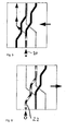
- vier mögliche Stellvorgänge, wie sie im ersten Ausführungsbeispiel der vorliegenden Erfindung möglich sind, in der Form einer abgewickelt gezeigten Nutenführung im Hubprofilelement der
Fig. 1 bis 4 ; - Fig. 9 bis Fig. 11:
- Längsschnitte durch eine elektromagnetische Stellvorrichtung, welche endseitig einen mehrgeteilten Stößel zur Realisierung der Stößeleinheit ausbildet.
- Die Abbildungen 1 bis 4 verdeutlichen, wie die Steuernuten (in der Art von Bahnen) im gezeigten Hubprofilelement (Nockenstück) verlaufen; wie in diesem Zusammenhang insbesondere die
Figuren 9 bis 11 erkennen lassen, weist die Stößeleinheit einen (einen schmalen Eingriffsbereich 11 ausbildenden) Innenstößel 10 sowie einen diesen umgebenden, hülsenförmigen Außenstößel 12 auf, wobei, in nachfolgend zu beschreibender Weise, beide Stößel separat durch elektromagnetische Ansteuerung unabhängig voneinander betätigbar sind. Der Innenstößel ermöglicht dabei das Realisieren einer größeren Eindringtiefe (in Verbindung mit einem schmaleren Nutenprofil,Abbildung 3 ,4 ), der breitere Außenstößel (Hohlstößel) kann nicht vollständig in die Tiefe einer einen derartigen schmalen Bodenbereich ausbildenden Nut eindringen. - Erfindungsgemäß vorteilhaft ermöglicht es die vorliegende Erfindung, mittels einer exemplarisch in den
Fig. 9 bis 11 gezeigten zweigeteilten Stößeleinheit, insgesamt eine Relativbewegung (Axialverschiebung) des Hubprofilelementes zwischen drei Positionen zu realisieren (mit der Wirkung, dass ein einziges -- mehrteiliges -- Stößelaggregat montiert werden muss und entsprechend kein zusätzlicher axialer Einbauraum mit entsprechenden Zusatzaufwand nötig ist). - Die Abwicklungen der
Fig. 5 bis 8 der jeweiligen Nutenbahnverläufe (Steuernuten) sind dabei symbolisiert durch dicke schwarze Striche bzw. Strichabschnitte (d.h. breite Nut) sowie gestrichelte/gepunktete Nutenbahnverläufe (schmale Nut), bei Überlappen auch innerhalb einer breiten Nut vertieft verlaufende schmale Nut. Weiterhin wird der zweigeteilte Stößel symbolisiert durch einen schwarzen Punkt (Fig. 1 ,Fig. 8 , nämlich Aktivierung durch den Innenstößel), sowie einen Kreis bzw. Ring als Symbol (Fig. 6 ,Fig. 7 ), entsprechend dem hülsenförmigen Hohl- bzw. Außenstößel. - Die
Fig. 5 verdeutlicht zunächst, wie durch Eingriff des ausgefahrenen Innenstößels 10 in die gezeigte tiefe Nut (Pfeilverlauf 20 derFig. 5 ) eine Rechtsverschiebung der Kulisse bewirkt wird, bis zur Position derFig. 6 (die Stößelposition verbleibt bei allen Beispielen unverändert). In der Position derFig. 6 würde, mit dem Zweck eines Zurückführens in eine Grundstellung (Mittelstellung), der Außenstößel die mit Pfeilen 22 beschriebene breite Nutenbahn beschreiben, so dass dann die gezeigte Kulisse von der rechten Position zurück in die Grundstellung (Mittelstellung) verschoben wird. -
Fig. 7 zeigt dann, wie aus der Mittelstellung eine Linksverschiebung bewirkt wird, mittels der Außenhülse;Fig. 8 verdeutlicht das Zurücksetzen aus der linken Position in die Grundstellung (Mittelstellung) mittels Innenstößel. Die Nut- bzw. Bahnverläufe derFig. 5 bis 8 dienen insoweit zur weiteren Verdeutlichung des konstruktiven Aufbaus des Hubprofilelements gemäß Ausführungsbeispiel derFig. 1 bis 4 . - Die
Fig. 9 bis 11 zeigen in schematischer Form die konstruktive Realisierung der Betätigungsvorrichtung als elektromagnetische Stellvorrichtung mit zwei Ankern; einem Innenstößel -(-anker) 10, welcher zum Zusammenwirken mit einem (stationären) Kern 13 einen Permanentmagneten 14 aufweist, und einem zweiten Anker 12a, welcher in den Hohlstößel übergeht. - Durch Bestromen einer Spule II (Bezugszeichen 16) wird der Flachanker 12a(damit der Hohlstößel 12) abwärts bewegt. Der Permanentmagnet 14 des Innenstößels 10 sorgt dagegen dafür, dass bei diesem Betriebsvorgang der Innenstößel am Kern 13 und damit in der in
Fig. 9 gezeigten, eingeschobenen Stellung verbleibt. -
Fig. 10 zeigt den auf diese Weise ausgefahrenen Hohlstößel; eine Markierung "X" einer der Spulen symbolisiert den bestromten Zustand. - Zum Ausfahren des Innenstößels muss der Permanentmagnet von einer (den Kern 13 umgebenden) Spule I (Bezugszeichen 18) abgestoßen werden (bei entsprechender Bestromung der Spule I). Hierbei wird automatisch der Hohlstößel (mittels des Flachankers) in der Zeichnungsebene nach oben gezogen, so dass der Hohlstößel nicht ausgefahren werden kann, es ergibt sich der Betriebszustand der
Abbildung 11 .
Claims (12)
- Vorrichtung zur Nockenwellenverstellung einer Brennkraftmaschine mit
einem auf oder an einer axial verschieblich gelagerten Nockenwelle drehfest vorgesehenen, eine Steuernut (20, 22) anbietenden Hubprofilelement
und einer Steuereinheit zum Bewirken einer vorbestimmten Axialverschiebung der Nockenwelle, wobei die Steuereinheit eine bevorzugt radial zur Nockenwelle bewegliche, zum steuerbaren Eingreifen in das Hubprofilelement ausgebildete Stößeleinheit (10,12) aufweist,
wobei
das Hubprofilelement eine erste Steuernut (20) ausbildet, welche zum Zusammenwirken mit der Stößeleinheit in einer ersten Eindringtiefe zum Beschreiben einer ersten Axialbewegung der Nockenwelle ausgebildet ist und
das Hubprofilelement eine zweite Steuernut (22) ausbildet, dadurch gekennzeichnet, dass die zweite Steuernut (22) zum Zusammenwirken mit der Stößeleinheit in einer zweiten, von der ersten Eindringtiefe verschiedenen Eindringtiefe zum Beschreiben einer zweiten, von der ersten Axialbewegung verschiedenen zweiten Axialbewegung der Nockenwelle ausgebildet ist. - Vorrichtung nach Anspruch 1, dadurch gekennzeichnet, dass die erste und die zweite Steuernut (20, 22) einander benachbart in einem gemeinsamen und/oder einstückig ausgebildeten Hubprofilelement vorgesehen sind.
- Vorrichtung nach Anspruch 1 oder 2, dadurch gekennzeichnet, dass die erste und die zweite Steuernut im Hubprofilelement zumindest bereichsweise ineinander übergehen.
- Vorrichtung nach einem der Ansprüche 1 bis 3, dadurch gekennzeichnet, dass die Stößeleinheit so ausgebildet ist, dass die Stößeleinheit zum Eingreifen in die erste und die zweite Steuernut eingriffsseitig zwischen der ersten und der zweiten Eindringtiefe umschaltbar und/oder zum Ausbilden eines in der Breite veränderlichen Eingriffsabschnitts (11,12) einstellbar oder umschaltbar ist.
- Vorrichtung nach einem der Ansprüche 1 bis 4, dadurch gekennzeichnet, dass die Stößeleinheit eingriffsseitig eine bevorzugt zylindrische Anordnung mit einem Innenstößel (10) und einem bevorzugt diesen konzentrisch umgebenden, hülsenartigen Außenstößel (12) aufweist.
- Vorrichtung nach Anspruch 5, dadurch gekennzeichnet, dass der Innenstößel und der Außenstößel der ersten (20) bzw. der zweiten (22) Steuernut und/oder der ersten bzw. der zweiten Eindringtiefe zugeordnet sind.
- Vorrichtung nach Anspruch 5 oder 6, dadurch gekennzeichnet, dass der Innenstößel und der Außenstößel unabhängig voneinander ansteuer- und/oder betreibbar ausgebildet sind.
- Vorrichtung nach einem der Ansprüche 1 bis 7, dadurch gekennzeichnet, dass die erste und die zweite Steuernut so ausgebildet sind, dass durch Wirkung der die Stößeleinheit ansteuernden Steuereinheit die Nockenwelle mittels der ersten Axialbewegung sowie der zweiten Axialbewegung aus einer Ausgangsstellung in eine erste axial verschobene Stellung und zurück in die Ausgangsstellung verstellt werden kann.
- Vorrichtung nach einem der Ansprüche 1 bis 8, dadurch gekennzeichnet, dass die Stößeleinheit (10, 12) mittels einer elektromagnetischen Stellvorrichtung (12, 13, 14, 18) angetrieben wird, wobei die Stößeleinheit mit einer als Realtion auf eine Bestromung einer bevorzugt stationären Spuleneinheit (18) bewegbaren Ankereinheit der elektromagnetischen Stellvorrichtung zusammenwirkt.
- Vorrichtung nach Anspruch 9, dadurch gekennzeichnet, dass die Ankereinheit entsprechend einer mehrteilig und unabhängig voneinander ansteuerbar realisierten Stößeleinheit mehrteilig mit einem ersten (12) und einem zweiten (14) Anker aufgebaut ist.
- Vorrichtung nach Anspruch 10, dadurch gekennzeichnet, dass einer der Anker zum Zusammenwirken mit einer bevorzugt stationären Kerneinheit eine Permanentmagneteinheit aufweist, die so eingerichtet ist, dass als Reaktion auf eine Bewegung des anderen Ankers die Permanentmagneteinheit das Bewegen des einen Ankers verhindert.
- Verfahren zur Nockenwellenverstellung einer Brennkraftmaschine, insbesondere Verfahren zum Betreiben einer Vorrichtung nach einem der Ansprüche 1 bis 11, gekennzeichnet durch die Schritte:- Ansteuern einer Stößeleinheit zum Zusammenwirken mit einer ersten Steuernut eines Hubprofilelements zum axialen Verschieben einer Nockenwelle in eine erste axial verschobene Stellung;- Ansteuern der Stößeleinheit zum Zusammenwirken mit einer im Hubprofilelement gebildeten zweiten Steuernut zum Verschieben der Nockenwelle aus der ersten axialen Verschiebeposition in eine zweite, von der ersten verschiedenen axiale Verschiebepostion,- wobei die Stößeleinheit zum Zusammenwirken mit der ersten und der zweiten Steuernut zwischen einer ersten und zweiten Eindringtiefe und/oder zwischen einer ersten und zweiten, für den Nuteneingriff wirksamen Eingriffsbreite umgeschaltet wird.
Priority Applications (1)
| Application Number | Priority Date | Filing Date | Title |
|---|---|---|---|
| EP13171054.3A EP2636860B1 (de) | 2007-08-07 | 2008-08-05 | Vorrichtung zur Nockenwellenverstellung einer Brennkraftmaschine |
Applications Claiming Priority (2)
| Application Number | Priority Date | Filing Date | Title |
|---|---|---|---|
| DE102007037232A DE102007037232A1 (de) | 2007-08-07 | 2007-08-07 | Vorrichtung zur Nockenwellenverstellung einer Brennkraftmaschine |
| PCT/EP2008/006417 WO2009018991A1 (de) | 2007-08-07 | 2008-08-05 | Vorrichtung zur nockenwellenverstellung einer brennkraftmaschine |
Related Child Applications (2)
| Application Number | Title | Priority Date | Filing Date |
|---|---|---|---|
| EP13171054.3A Division EP2636860B1 (de) | 2007-08-07 | 2008-08-05 | Vorrichtung zur Nockenwellenverstellung einer Brennkraftmaschine |
| EP13171054.3 Division-Into | 2013-06-07 |
Publications (2)
| Publication Number | Publication Date |
|---|---|
| EP2082120A1 EP2082120A1 (de) | 2009-07-29 |
| EP2082120B1 true EP2082120B1 (de) | 2013-10-09 |
Family
ID=40029144
Family Applications (2)
| Application Number | Title | Priority Date | Filing Date |
|---|---|---|---|
| EP13171054.3A Active EP2636860B1 (de) | 2007-08-07 | 2008-08-05 | Vorrichtung zur Nockenwellenverstellung einer Brennkraftmaschine |
| EP08785345.3A Active EP2082120B1 (de) | 2007-08-07 | 2008-08-05 | Vorrichtung zur nockenwellenverstellung einer brennkraftmaschine |
Family Applications Before (1)
| Application Number | Title | Priority Date | Filing Date |
|---|---|---|---|
| EP13171054.3A Active EP2636860B1 (de) | 2007-08-07 | 2008-08-05 | Vorrichtung zur Nockenwellenverstellung einer Brennkraftmaschine |
Country Status (7)
| Country | Link |
|---|---|
| US (1) | US8186320B2 (de) |
| EP (2) | EP2636860B1 (de) |
| JP (1) | JP5241836B2 (de) |
| CN (1) | CN101548069B (de) |
| DE (1) | DE102007037232A1 (de) |
| RU (1) | RU2476692C2 (de) |
| WO (1) | WO2009018991A1 (de) |
Families Citing this family (45)
| Publication number | Priority date | Publication date | Assignee | Title |
|---|---|---|---|---|
| DE102007010149A1 (de) * | 2007-03-02 | 2008-09-04 | Audi Ag | Ventiltrieb für Gaswechselventile einer Brennkraftmaschine mit verschiebbarem Nockenträger und Doppelschneckentrieb |
| DE102007029116A1 (de) | 2007-06-25 | 2009-01-02 | Continental Automotive Gmbh | Verfahren zum Betreiben eines Mikrocontrollers und einer Ausführungseinheit sowie ein Mikrocontroller und eine Ausführungseinheit |
| DE102008029325A1 (de) * | 2008-06-20 | 2009-12-24 | Daimler Ag | Ventiltriebvorrichtung |
| DE102008029349A1 (de) * | 2008-06-20 | 2009-12-24 | Daimler Ag | Ventiltriebvorrichtung |
| DE102008060170A1 (de) * | 2008-11-27 | 2010-06-02 | Dr.Ing.H.C.F.Porsche Aktiengesellschaft | Ventiltrieb einer Brennkraftmaschine |
| DE102008060167B4 (de) | 2008-11-27 | 2021-05-27 | Dr. Ing. H.C. F. Porsche Aktiengesellschaft | Ventiltrieb einer Brennkraftmaschine |
| DE202009015465U1 (de) | 2009-02-14 | 2010-02-25 | Schaeffler Kg | Ventiltrieb einer Brennkraftmaschine |
| DE102010013216B4 (de) * | 2009-04-04 | 2022-04-28 | Schaeffler Technologies AG & Co. KG | Ventiltrieb einer Brennkraftmaschine |
| DE202009011804U1 (de) * | 2009-09-01 | 2011-01-13 | Eto Magnetic Gmbh | Vorrichtung zur Nockenwellenverstellung einer Brennkraftmaschine |
| DE102009056609A1 (de) * | 2009-12-02 | 2011-06-09 | Schaeffler Technologies Gmbh & Co. Kg | Elektromagnetische Stellvorrichtung |
| JP5510095B2 (ja) * | 2010-06-15 | 2014-06-04 | トヨタ自動車株式会社 | 内燃機関の可変動弁装置 |
| DE102010053359A1 (de) * | 2010-12-03 | 2012-06-06 | Schaeffler Technologies Gmbh & Co. Kg | Schiebenockensystem mit Schiebenuten und Arretierungen |
| DE102012204621A1 (de) * | 2012-03-22 | 2013-09-26 | Schaeffler Technologies AG & Co. KG | Nockenstück für einen variablen Schiebenockenventiltrieb |
| JP6003185B2 (ja) * | 2012-04-25 | 2016-10-05 | マツダ株式会社 | エンジンのカムシフティング装置 |
| DE102012210212B4 (de) * | 2012-06-18 | 2014-12-11 | Schaeffler Technologies Gmbh & Co. Kg | Schiebenockensystem einer Hubkolbenbrennkraftmaschine mit X-förmig angeordneten Schiebenuten und Weichen |
| DE102012106824A1 (de) * | 2012-07-26 | 2014-01-30 | Eto Magnetic Gmbh | Elektromagnetische Stellvorrichtung |
| DE102012222113A1 (de) * | 2012-12-04 | 2014-06-18 | Schaeffler Technologies Gmbh & Co. Kg | Ventiltrieb eines Verbrennungsmotors |
| JP6056485B2 (ja) * | 2013-01-11 | 2017-01-11 | スズキ株式会社 | 内燃機関の可変動弁装置 |
| DE102013201827A1 (de) * | 2013-02-05 | 2014-08-07 | Schaeffler Technologies Gmbh & Co. Kg | Diagnoseverfahren eines Ventiltrieb-Aktuators |
| DE102013202132A1 (de) * | 2013-02-08 | 2014-08-14 | Schaeffler Technologies Gmbh & Co. Kg | Schiebenockenaktor mit Abdichtung |
| DE102013102241A1 (de) | 2013-03-06 | 2014-09-11 | Kendrion (Villingen) Gmbh | Elektromagnetische Stellvorrichtung, insbesondere zur Nockenwellenverstellung einer Brennkraftmaschine |
| KR101448778B1 (ko) * | 2013-03-08 | 2014-10-13 | 현대자동차 주식회사 | 다단 가변 밸브 리프트 장치 |
| CN103306776B (zh) * | 2013-06-28 | 2015-09-09 | 长城汽车股份有限公司 | 用于发动机的可变气门升程装置、发动机和车辆 |
| CN103437894B (zh) * | 2013-08-13 | 2017-03-22 | 奇瑞汽车股份有限公司 | 发动机停缸控制装置及控制方法 |
| DE102013221244A1 (de) | 2013-10-21 | 2015-04-23 | Volkswagen Aktiengesellschaft | Vorrichtung zur Nockenwellenverstellung einer Brennkraftmaschine |
| DE102014217167A1 (de) | 2014-08-28 | 2016-03-17 | Schaeffler Technologies AG & Co. KG | Aktorvorrichtung in modularem Aufbau |
| DE102014217755A1 (de) | 2014-09-05 | 2016-03-10 | Schaeffler Technologies AG & Co. KG | Aktorvorrichtung für Schiebenockensysteme |
| DE102014220266A1 (de) | 2014-10-07 | 2016-04-07 | Schaeffler Technologies AG & Co. KG | Aktorvorrichtung mit Hülsenabstützung an einer Brennkraftmaschine |
| EP3016117B1 (de) | 2014-10-31 | 2017-12-06 | Husco Automotive Holdings LLC | Druckstiftaktuatorvorrichtung |
| DE102014017036B3 (de) * | 2014-11-18 | 2016-03-24 | Audi Ag | Ventiltrieb für eine Brennkraftmaschine sowie entsprechende Brennkraftmaschine |
| DE102015103761A1 (de) | 2015-03-13 | 2016-09-29 | Kendrion (Villingen) Gmbh | Stellelement zum axialen Verschieben einer entlang einer Nockenwellenachse verschiebbar gelagerten Nockenwelle |
| DE112016004372T5 (de) | 2015-11-06 | 2018-06-07 | Borgwarner Inc. | Ventilbetätigungssystem, das einen variablen ventilhub und/oder variable ventilzeitsteuerung bereitstellt |
| DE102016005454A1 (de) * | 2016-05-03 | 2017-11-09 | Daimler Ag | Ventiltriebvorrichtung, insbesondere für eine Brennkraftmaschine |
| CN105850316A (zh) * | 2016-06-01 | 2016-08-17 | 黑龙江省农垦科学院农业工程研究所 | 栽植臂摆动控制组合凸轮 |
| CN106121764A (zh) * | 2016-07-18 | 2016-11-16 | 杰锋汽车动力系统股份有限公司 | 一种用于可变气门升程系统的凸轮轴调节装置 |
| US20180094554A1 (en) * | 2016-10-05 | 2018-04-05 | GM Global Technology Operations LLC | Variable camshaft |
| DE102016220612A1 (de) * | 2016-10-20 | 2018-04-26 | Mahle International Gmbh | Ventiltrieb für eine Brennkraftmaschine |
| DE102016124851A1 (de) * | 2016-12-19 | 2018-06-21 | Volkswagen Aktiengesellschaft | Ventiltrieb einer Brennkraftmaschine |
| JP6438987B2 (ja) * | 2017-02-17 | 2018-12-19 | 本田技研工業株式会社 | 可変動弁装置 |
| DE102017114575A1 (de) * | 2017-06-29 | 2019-01-03 | Man Truck & Bus Ag | Variabler Ventiltrieb |
| DE102017116987A1 (de) * | 2017-07-27 | 2019-01-31 | Man Truck & Bus Ag | Schiebenockensystem und Verfahren zum Betreiben eines Verbrennungsmotors |
| KR102177594B1 (ko) | 2017-08-17 | 2020-11-11 | 바르실라 핀랜드 오이 | 내연 피스톤 엔진을 위한 캠샤프트 어셈블리 및 적어도 2 개의 작동 모드들에서 작동하도록 내연 피스톤 엔진을 전환하는 방법 |
| DE102017121947A1 (de) * | 2017-09-21 | 2019-03-21 | Kendrion (Villingen) Gmbh | Stellvorrichtung mit einem abgedichteten Führungszylinder |
| DE102018110705A1 (de) * | 2018-05-04 | 2019-11-07 | Man Truck & Bus Se | Variabler Ventiltrieb |
| DE102019107626A1 (de) | 2019-03-25 | 2020-10-01 | Thyssenkrupp Ag | Schiebenockensystem und Motor |
Family Cites Families (20)
| Publication number | Priority date | Publication date | Assignee | Title |
|---|---|---|---|---|
| GB191210648A (en) | 1911-07-24 | 1912-10-24 | Juhana Kylliainen | Improvements in or relating to Reversing Gear for Internal Combustion Engines. |
| GB191410648A (en) | 1914-04-30 | 1914-11-19 | Robert William Richards | Improvements in the Lubrication of Internal Combustion Engines. |
| JPS5244314A (en) | 1975-10-06 | 1977-04-07 | Mitsubishi Motors Corp | Variable valve-timing device |
| JPS60263762A (ja) * | 1984-06-13 | 1985-12-27 | Japan Tobacco Inc | 往復軸駆動装置 |
| JPS62184118U (de) * | 1986-05-16 | 1987-11-21 | ||
| JPH0450572Y2 (de) * | 1987-12-25 | 1992-11-30 | ||
| GB9021270D0 (en) * | 1990-10-01 | 1990-11-14 | Mitchell Stephen W | Improvements in or relating to driving connections between two rotatable bodies |
| AT408127B (de) * | 1992-07-13 | 2001-09-25 | Avl Verbrennungskraft Messtech | Brennkraftmaschine mit mindestens einer durch eine verstellvorrichtung axial verschiebbaren nockenwelle |
| DE19611641C1 (de) * | 1996-03-25 | 1997-06-05 | Porsche Ag | Ventiltrieb einer Brennkraftmaschine |
| JP4259017B2 (ja) * | 2001-05-31 | 2009-04-30 | トヨタ自動車株式会社 | 内燃機関の可変動弁装置 |
| DE10148177B4 (de) * | 2001-09-28 | 2015-05-13 | Schaeffler Technologies AG & Co. KG | Ventiltrieb mit Ventilhubumschaltung für die Gaswechselventiele eines 4-Takt-Verbrennungsmotors |
| DE10148178A1 (de) * | 2001-09-28 | 2003-04-17 | Ina Schaeffler Kg | Verfahren und Vorrichtung zur Senkung von Kraftstoffverbrauch und Schadstoffemission eines 4-Takt-Verbrennungsmotors |
| DE102004011586A1 (de) * | 2003-03-21 | 2004-10-07 | Audi Ag | Ventiltrieb einer einen Zylinderkopf aufweisenden Brennkraftmaschine |
| EP1503048B1 (de) * | 2003-07-19 | 2008-10-08 | Dr. Ing. h.c. F. Porsche Aktiengesellschaft | Ventiltrieb für eine Brennkraftmaschine |
| DE102004008670B4 (de) * | 2004-02-21 | 2013-04-11 | Schaeffler Technologies AG & Co. KG | Ventiltrieb mit Nockenumschaltung für die Gaswechselventile eines 4-Takt-Verbrennungsmotors |
| DE102004037198A1 (de) * | 2004-07-30 | 2006-03-23 | Ina-Schaeffler Kg | Ventiltrieb einer Brennkraftmaschine |
| DE102005003079B4 (de) * | 2005-01-22 | 2014-12-31 | Audi Ag | Brennkraftmaschine mit einem Ventiltrieb |
| DE102007010149A1 (de) * | 2007-03-02 | 2008-09-04 | Audi Ag | Ventiltrieb für Gaswechselventile einer Brennkraftmaschine mit verschiebbarem Nockenträger und Doppelschneckentrieb |
| DE102008060167B4 (de) * | 2008-11-27 | 2021-05-27 | Dr. Ing. H.C. F. Porsche Aktiengesellschaft | Ventiltrieb einer Brennkraftmaschine |
| DE202009011804U1 (de) * | 2009-09-01 | 2011-01-13 | Eto Magnetic Gmbh | Vorrichtung zur Nockenwellenverstellung einer Brennkraftmaschine |
-
2007
- 2007-08-07 DE DE102007037232A patent/DE102007037232A1/de not_active Withdrawn
-
2008
- 2008-08-05 EP EP13171054.3A patent/EP2636860B1/de active Active
- 2008-08-05 CN CN200880000894.7A patent/CN101548069B/zh active Active
- 2008-08-05 US US12/514,510 patent/US8186320B2/en active Active
- 2008-08-05 WO PCT/EP2008/006417 patent/WO2009018991A1/de not_active Ceased
- 2008-08-05 JP JP2010519371A patent/JP5241836B2/ja not_active Expired - Fee Related
- 2008-08-05 EP EP08785345.3A patent/EP2082120B1/de active Active
- 2008-08-05 RU RU2009116263/06A patent/RU2476692C2/ru active
Also Published As
| Publication number | Publication date |
|---|---|
| CN101548069A (zh) | 2009-09-30 |
| RU2476692C2 (ru) | 2013-02-27 |
| EP2082120A1 (de) | 2009-07-29 |
| DE102007037232A1 (de) | 2009-02-12 |
| CN101548069B (zh) | 2014-01-22 |
| JP5241836B2 (ja) | 2013-07-17 |
| JP2010535964A (ja) | 2010-11-25 |
| US8186320B2 (en) | 2012-05-29 |
| US20100126445A1 (en) | 2010-05-27 |
| RU2009116263A (ru) | 2010-11-10 |
| WO2009018991A1 (de) | 2009-02-12 |
| EP2636860A1 (de) | 2013-09-11 |
| EP2636860B1 (de) | 2014-12-17 |
Similar Documents
| Publication | Publication Date | Title |
|---|---|---|
| EP2636860B1 (de) | Vorrichtung zur Nockenwellenverstellung einer Brennkraftmaschine | |
| EP2823203B1 (de) | Verriegelungseinheit, insbesondere für eine parksperre eines automatikgetriebes | |
| DE102009049009B4 (de) | Aktuator für eine Verbrennungskraftmaschine | |
| EP3025358B1 (de) | Elektromagnetische stellvorrichtung und system zur verstellung einer funktionalität eines kraftfahrzeugaggregats | |
| WO2008052884A1 (de) | Stellvorrichtung | |
| WO2011012189A1 (de) | Ventiltriebvorrichtung | |
| WO2011026545A2 (de) | Vorrichtung zur nockenwellenverstellung einer brennkraftmaschine | |
| EP3334915A1 (de) | Hubkolbenmaschine, insbesondere brennkraftmaschine | |
| EP3146166B1 (de) | Nockenwelle | |
| DE102019204589A1 (de) | Ventiltrieb für eine Brennkraftmaschine | |
| EP2345800A2 (de) | Elektromagnetische Stellvorrichtung | |
| DE102016210976A1 (de) | Ventiltrieb für eine Brennkraftmaschine | |
| EP2929550B1 (de) | Elektromagnetische stellvorrichtung | |
| EP3222828A2 (de) | Ventiltrieb für eine brennkraftmaschine | |
| EP2724354B1 (de) | Elektromagnetische stellvorrichtung sowie nockenwellenverstellvorrichtung | |
| DE102017205571A1 (de) | Ventiltrieb für eine Brennkraftmaschine | |
| DE102013102241A1 (de) | Elektromagnetische Stellvorrichtung, insbesondere zur Nockenwellenverstellung einer Brennkraftmaschine | |
| EP2191156B1 (de) | Elektrisch betätigte kupplungseinrichtung | |
| DE102011117244A1 (de) | Ventiltrieb für eine Brennkraftmaschine | |
| DE102017210281B4 (de) | Mehrstufig zu schaltende Schiebenockeneinrichtung | |
| EP2288834B1 (de) | Azimutal-magnetaktor | |
| EP2446522B1 (de) | Linearstelleinheit für eine schalteinrichtung eines getriebes | |
| EP3161282B1 (de) | Vorrichtung zur nockenwellenverstellung einer brennkraftmaschine | |
| EP3857576B1 (de) | Elektromagnetische stellvorrichtung mit adaptierbarer stösselanordnung | |
| DE102014102426B4 (de) | Elektromagnetische Stellvorrichtung und deren Verwendung sowie Nockenwellenverstellsystem |
Legal Events
| Date | Code | Title | Description |
|---|---|---|---|
| PUAI | Public reference made under article 153(3) epc to a published international application that has entered the european phase |
Free format text: ORIGINAL CODE: 0009012 |
|
| 17P | Request for examination filed |
Effective date: 20090513 |
|
| AK | Designated contracting states |
Kind code of ref document: A1 Designated state(s): AT BE BG CH CY CZ DE DK EE ES FI FR GB GR HR HU IE IS IT LI LT LU LV MC MT NL NO PL PT RO SE SI SK TR |
|
| DAX | Request for extension of the european patent (deleted) | ||
| 17Q | First examination report despatched |
Effective date: 20110609 |
|
| GRAP | Despatch of communication of intention to grant a patent |
Free format text: ORIGINAL CODE: EPIDOSNIGR1 |
|
| GRAS | Grant fee paid |
Free format text: ORIGINAL CODE: EPIDOSNIGR3 |
|
| GRAA | (expected) grant |
Free format text: ORIGINAL CODE: 0009210 |
|
| AK | Designated contracting states |
Kind code of ref document: B1 Designated state(s): AT BE BG CH CY CZ DE DK EE ES FI FR GB GR HR HU IE IS IT LI LT LU LV MC MT NL NO PL PT RO SE SI SK TR |
|
| REG | Reference to a national code |
Ref country code: GB Ref legal event code: FG4D Free format text: NOT ENGLISH |
|
| REG | Reference to a national code |
Ref country code: CH Ref legal event code: EP Ref country code: AT Ref legal event code: REF Ref document number: 635666 Country of ref document: AT Kind code of ref document: T Effective date: 20131015 |
|
| REG | Reference to a national code |
Ref country code: IE Ref legal event code: FG4D Free format text: LANGUAGE OF EP DOCUMENT: GERMAN |
|
| REG | Reference to a national code |
Ref country code: DE Ref legal event code: R096 Ref document number: 502008010789 Country of ref document: DE Effective date: 20131205 |
|
| REG | Reference to a national code |
Ref country code: NL Ref legal event code: VDEP Effective date: 20131009 |
|
| PG25 | Lapsed in a contracting state [announced via postgrant information from national office to epo] |
Ref country code: SI Free format text: LAPSE BECAUSE OF FAILURE TO SUBMIT A TRANSLATION OF THE DESCRIPTION OR TO PAY THE FEE WITHIN THE PRESCRIBED TIME-LIMIT Effective date: 20131009 |
|
| REG | Reference to a national code |
Ref country code: LT Ref legal event code: MG4D |
|
| PG25 | Lapsed in a contracting state [announced via postgrant information from national office to epo] |
Ref country code: NO Free format text: LAPSE BECAUSE OF FAILURE TO SUBMIT A TRANSLATION OF THE DESCRIPTION OR TO PAY THE FEE WITHIN THE PRESCRIBED TIME-LIMIT Effective date: 20140109 Ref country code: HR Free format text: LAPSE BECAUSE OF FAILURE TO SUBMIT A TRANSLATION OF THE DESCRIPTION OR TO PAY THE FEE WITHIN THE PRESCRIBED TIME-LIMIT Effective date: 20131009 Ref country code: FI Free format text: LAPSE BECAUSE OF FAILURE TO SUBMIT A TRANSLATION OF THE DESCRIPTION OR TO PAY THE FEE WITHIN THE PRESCRIBED TIME-LIMIT Effective date: 20131009 Ref country code: LT Free format text: LAPSE BECAUSE OF FAILURE TO SUBMIT A TRANSLATION OF THE DESCRIPTION OR TO PAY THE FEE WITHIN THE PRESCRIBED TIME-LIMIT Effective date: 20131009 Ref country code: NL Free format text: LAPSE BECAUSE OF FAILURE TO SUBMIT A TRANSLATION OF THE DESCRIPTION OR TO PAY THE FEE WITHIN THE PRESCRIBED TIME-LIMIT Effective date: 20131009 Ref country code: IS Free format text: LAPSE BECAUSE OF FAILURE TO SUBMIT A TRANSLATION OF THE DESCRIPTION OR TO PAY THE FEE WITHIN THE PRESCRIBED TIME-LIMIT Effective date: 20140209 Ref country code: SE Free format text: LAPSE BECAUSE OF FAILURE TO SUBMIT A TRANSLATION OF THE DESCRIPTION OR TO PAY THE FEE WITHIN THE PRESCRIBED TIME-LIMIT Effective date: 20131009 |
|
| PG25 | Lapsed in a contracting state [announced via postgrant information from national office to epo] |
Ref country code: CY Free format text: LAPSE BECAUSE OF FAILURE TO SUBMIT A TRANSLATION OF THE DESCRIPTION OR TO PAY THE FEE WITHIN THE PRESCRIBED TIME-LIMIT Effective date: 20131009 Ref country code: ES Free format text: LAPSE BECAUSE OF FAILURE TO SUBMIT A TRANSLATION OF THE DESCRIPTION OR TO PAY THE FEE WITHIN THE PRESCRIBED TIME-LIMIT Effective date: 20131009 Ref country code: PL Free format text: LAPSE BECAUSE OF FAILURE TO SUBMIT A TRANSLATION OF THE DESCRIPTION OR TO PAY THE FEE WITHIN THE PRESCRIBED TIME-LIMIT Effective date: 20131009 Ref country code: LV Free format text: LAPSE BECAUSE OF FAILURE TO SUBMIT A TRANSLATION OF THE DESCRIPTION OR TO PAY THE FEE WITHIN THE PRESCRIBED TIME-LIMIT Effective date: 20131009 |
|
| PG25 | Lapsed in a contracting state [announced via postgrant information from national office to epo] |
Ref country code: PT Free format text: LAPSE BECAUSE OF FAILURE TO SUBMIT A TRANSLATION OF THE DESCRIPTION OR TO PAY THE FEE WITHIN THE PRESCRIBED TIME-LIMIT Effective date: 20140210 |
|
| REG | Reference to a national code |
Ref country code: DE Ref legal event code: R097 Ref document number: 502008010789 Country of ref document: DE |
|
| PG25 | Lapsed in a contracting state [announced via postgrant information from national office to epo] |
Ref country code: EE Free format text: LAPSE BECAUSE OF FAILURE TO SUBMIT A TRANSLATION OF THE DESCRIPTION OR TO PAY THE FEE WITHIN THE PRESCRIBED TIME-LIMIT Effective date: 20131009 |
|
| PLBE | No opposition filed within time limit |
Free format text: ORIGINAL CODE: 0009261 |
|
| STAA | Information on the status of an ep patent application or granted ep patent |
Free format text: STATUS: NO OPPOSITION FILED WITHIN TIME LIMIT |
|
| PG25 | Lapsed in a contracting state [announced via postgrant information from national office to epo] |
Ref country code: CZ Free format text: LAPSE BECAUSE OF FAILURE TO SUBMIT A TRANSLATION OF THE DESCRIPTION OR TO PAY THE FEE WITHIN THE PRESCRIBED TIME-LIMIT Effective date: 20131009 Ref country code: SK Free format text: LAPSE BECAUSE OF FAILURE TO SUBMIT A TRANSLATION OF THE DESCRIPTION OR TO PAY THE FEE WITHIN THE PRESCRIBED TIME-LIMIT Effective date: 20131009 Ref country code: RO Free format text: LAPSE BECAUSE OF FAILURE TO SUBMIT A TRANSLATION OF THE DESCRIPTION OR TO PAY THE FEE WITHIN THE PRESCRIBED TIME-LIMIT Effective date: 20131009 |
|
| 26N | No opposition filed |
Effective date: 20140710 |
|
| PG25 | Lapsed in a contracting state [announced via postgrant information from national office to epo] |
Ref country code: DK Free format text: LAPSE BECAUSE OF FAILURE TO SUBMIT A TRANSLATION OF THE DESCRIPTION OR TO PAY THE FEE WITHIN THE PRESCRIBED TIME-LIMIT Effective date: 20131009 |
|
| REG | Reference to a national code |
Ref country code: DE Ref legal event code: R097 Ref document number: 502008010789 Country of ref document: DE Effective date: 20140710 |
|
| REG | Reference to a national code |
Ref country code: HU Ref legal event code: AG4A Ref document number: E020795 Country of ref document: HU |
|
| PG25 | Lapsed in a contracting state [announced via postgrant information from national office to epo] |
Ref country code: LU Free format text: LAPSE BECAUSE OF FAILURE TO SUBMIT A TRANSLATION OF THE DESCRIPTION OR TO PAY THE FEE WITHIN THE PRESCRIBED TIME-LIMIT Effective date: 20140805 Ref country code: MC Free format text: LAPSE BECAUSE OF FAILURE TO SUBMIT A TRANSLATION OF THE DESCRIPTION OR TO PAY THE FEE WITHIN THE PRESCRIBED TIME-LIMIT Effective date: 20131009 |
|
| REG | Reference to a national code |
Ref country code: CH Ref legal event code: PL |
|
| GBPC | Gb: european patent ceased through non-payment of renewal fee |
Effective date: 20140805 |
|
| PG25 | Lapsed in a contracting state [announced via postgrant information from national office to epo] |
Ref country code: CH Free format text: LAPSE BECAUSE OF NON-PAYMENT OF DUE FEES Effective date: 20140831 Ref country code: BE Free format text: LAPSE BECAUSE OF NON-PAYMENT OF DUE FEES Effective date: 20140831 Ref country code: LI Free format text: LAPSE BECAUSE OF NON-PAYMENT OF DUE FEES Effective date: 20140831 |
|
| REG | Reference to a national code |
Ref country code: IE Ref legal event code: MM4A |
|
| PG25 | Lapsed in a contracting state [announced via postgrant information from national office to epo] |
Ref country code: GB Free format text: LAPSE BECAUSE OF NON-PAYMENT OF DUE FEES Effective date: 20140805 |
|
| PG25 | Lapsed in a contracting state [announced via postgrant information from national office to epo] |
Ref country code: IE Free format text: LAPSE BECAUSE OF NON-PAYMENT OF DUE FEES Effective date: 20140805 |
|
| REG | Reference to a national code |
Ref country code: AT Ref legal event code: MM01 Ref document number: 635666 Country of ref document: AT Kind code of ref document: T Effective date: 20140805 |
|
| PG25 | Lapsed in a contracting state [announced via postgrant information from national office to epo] |
Ref country code: AT Free format text: LAPSE BECAUSE OF NON-PAYMENT OF DUE FEES Effective date: 20140805 |
|
| PG25 | Lapsed in a contracting state [announced via postgrant information from national office to epo] |
Ref country code: BG Free format text: LAPSE BECAUSE OF FAILURE TO SUBMIT A TRANSLATION OF THE DESCRIPTION OR TO PAY THE FEE WITHIN THE PRESCRIBED TIME-LIMIT Effective date: 20131009 |
|
| PG25 | Lapsed in a contracting state [announced via postgrant information from national office to epo] |
Ref country code: GR Free format text: LAPSE BECAUSE OF FAILURE TO SUBMIT A TRANSLATION OF THE DESCRIPTION OR TO PAY THE FEE WITHIN THE PRESCRIBED TIME-LIMIT Effective date: 20140110 Ref country code: MT Free format text: LAPSE BECAUSE OF FAILURE TO SUBMIT A TRANSLATION OF THE DESCRIPTION OR TO PAY THE FEE WITHIN THE PRESCRIBED TIME-LIMIT Effective date: 20131009 |
|
| PG25 | Lapsed in a contracting state [announced via postgrant information from national office to epo] |
Ref country code: TR Free format text: LAPSE BECAUSE OF FAILURE TO SUBMIT A TRANSLATION OF THE DESCRIPTION OR TO PAY THE FEE WITHIN THE PRESCRIBED TIME-LIMIT Effective date: 20131009 |
|
| REG | Reference to a national code |
Ref country code: FR Ref legal event code: PLFP Year of fee payment: 9 |
|
| REG | Reference to a national code |
Ref country code: FR Ref legal event code: PLFP Year of fee payment: 10 |
|
| REG | Reference to a national code |
Ref country code: FR Ref legal event code: PLFP Year of fee payment: 11 |
|
| REG | Reference to a national code |
Ref country code: DE Ref legal event code: R082 Ref document number: 502008010789 Country of ref document: DE Representative=s name: PATENT- UND RECHTSANWALTSKANZLEI DAUB, DE Ref country code: DE Ref legal event code: R082 Ref document number: 502008010789 Country of ref document: DE Representative=s name: DAUB PARTG MBB, DE |
|
| PGFP | Annual fee paid to national office [announced via postgrant information from national office to epo] |
Ref country code: DE Payment date: 20240819 Year of fee payment: 17 |
|
| PGFP | Annual fee paid to national office [announced via postgrant information from national office to epo] |
Ref country code: FR Payment date: 20240823 Year of fee payment: 17 |
|
| PGFP | Annual fee paid to national office [announced via postgrant information from national office to epo] |
Ref country code: HU Payment date: 20240801 Year of fee payment: 17 |
|
| PGFP | Annual fee paid to national office [announced via postgrant information from national office to epo] |
Ref country code: IT Payment date: 20240830 Year of fee payment: 17 |
|
| REG | Reference to a national code |
Ref country code: DE Ref legal event code: R119 Ref document number: 502008010789 Country of ref document: DE |
|
| PG25 | Lapsed in a contracting state [announced via postgrant information from national office to epo] |
Ref country code: HU Free format text: LAPSE BECAUSE OF NON-PAYMENT OF DUE FEES Effective date: 20250806 |