EP2081202A2 - Appareil de commutation, notamment disjoncteur - Google Patents
Appareil de commutation, notamment disjoncteur Download PDFInfo
- Publication number
- EP2081202A2 EP2081202A2 EP09150338A EP09150338A EP2081202A2 EP 2081202 A2 EP2081202 A2 EP 2081202A2 EP 09150338 A EP09150338 A EP 09150338A EP 09150338 A EP09150338 A EP 09150338A EP 2081202 A2 EP2081202 A2 EP 2081202A2
- Authority
- EP
- European Patent Office
- Prior art keywords
- switching device
- pressure
- gas outlet
- switching
- pressure sensor
- Prior art date
- Legal status (The legal status is an assumption and is not a legal conclusion. Google has not performed a legal analysis and makes no representation as to the accuracy of the status listed.)
- Withdrawn
Links
Images

Classifications
-
- H—ELECTRICITY
- H01—ELECTRIC ELEMENTS
- H01H—ELECTRIC SWITCHES; RELAYS; SELECTORS; EMERGENCY PROTECTIVE DEVICES
- H01H9/00—Details of switching devices, not covered by groups H01H1/00 - H01H7/00
- H01H9/30—Means for extinguishing or preventing arc between current-carrying parts
- H01H9/34—Stationary parts for restricting or subdividing the arc, e.g. barrier plate
- H01H9/342—Venting arrangements for arc chutes
-
- H—ELECTRICITY
- H01—ELECTRIC ELEMENTS
- H01H—ELECTRIC SWITCHES; RELAYS; SELECTORS; EMERGENCY PROTECTIVE DEVICES
- H01H1/00—Contacts
- H01H1/12—Contacts characterised by the manner in which co-operating contacts engage
- H01H1/14—Contacts characterised by the manner in which co-operating contacts engage by abutting
- H01H1/20—Bridging contacts
- H01H1/2041—Rotating bridge
-
- H—ELECTRICITY
- H01—ELECTRIC ELEMENTS
- H01H—ELECTRIC SWITCHES; RELAYS; SELECTORS; EMERGENCY PROTECTIVE DEVICES
- H01H71/00—Details of the protective switches or relays covered by groups H01H73/00 - H01H83/00
- H01H71/10—Operating or release mechanisms
- H01H71/12—Automatic release mechanisms with or without manual release
- H01H71/24—Electromagnetic mechanisms
- H01H71/2418—Electromagnetic mechanisms combined with an electrodynamic current limiting mechanism
- H01H2071/2427—Electromagnetic mechanisms combined with an electrodynamic current limiting mechanism with blow-off movement tripping mechanism, e.g. electrodynamic effect on contacts trips the traditional trip device before it can unlatch the spring mechanism by itself
-
- H—ELECTRICITY
- H01—ELECTRIC ELEMENTS
- H01H—ELECTRIC SWITCHES; RELAYS; SELECTORS; EMERGENCY PROTECTIVE DEVICES
- H01H77/00—Protective overload circuit-breaking switches operated by excess current and requiring separate action for resetting
- H01H77/02—Protective overload circuit-breaking switches operated by excess current and requiring separate action for resetting in which the excess current itself provides the energy for opening the contacts, and having a separate reset mechanism
- H01H2077/025—Protective overload circuit-breaking switches operated by excess current and requiring separate action for resetting in which the excess current itself provides the energy for opening the contacts, and having a separate reset mechanism with pneumatic means, e.g. by arc pressure
Definitions
- the invention relates to a switching device, in particular a power switching device, which has at least two switching contacts for interrupting a current path.
- the switching contacts are arranged in a quenching chamber for extinguishing an arc that occurs when opening.
- the quenching chamber leads to the escape of an overpressure generated when the arc is pulled into a gas outlet channel.
- a pressure sensor is present in the gas outlet channel, which upon reaching a predeterminable pressure value triggers an at least indirectly connected switching mechanism of the switching device.
- the invention relates in particular to electrical switching devices, in particular to power switching devices in the low voltage range, that is up to voltages of about 1000 volts.
- Such switching devices are designed in particular for interrupting current paths in the event of a short circuit or in an overcurrent situation.
- the switching devices can be single-pole or multi-pole, in particular three-pole. You can have one or more switching contact pairs per pole.
- the switching devices for switching off currents of more than 100 A, in particular of several kA, designed.
- EP 0 455 564 B1 is a trigger for a circuit breaker with insulating material known, which comprises two pole per pole in the closed position of the circuit breaker resiliently pressed against each other.
- the contacts can be separated by the action of electrodynamic recoil forces as the current flowing through the contacts exceeds a certain threshold, so as to effect a limitation of said current.
- the trigger comprises an overload and / or short-circuit detection element for acting on a case of failure, the automatic shutdown of the circuit breaker causing switching mechanism '.
- the trigger comprises an actuator which responds to an overpressure generated in the separation zone of said contacts by an electric arc generated during electrodynamic recoil of the contacts to actuate the circuit breaker of the circuit breaker.
- the actuator is a gas-tight unit which is connected exclusively to the separation zone of the contacts and comprises a movable element such as a piston or a diaphragm with a limited control stroke.
- the movable element is acted upon on the one hand with the said overpressure and on the other hand by a return device with adapted effective force. Its displacement causes the triggering of said circuit breaker 'of the circuit breaker, wherein the said adapted action force return device is dimensioned so that an accidental tripping is prevented in a simple overload or response of a downstream current-limiting circuit breaker.
- a trigger with a movable anchor known.
- the anchor is designed as a bimetal and acted upon by the electromagnetic release.
- An extension of the armature protrudes into the gas outlet channel of the arc quenching chamber. When switching off the armature is transferred by the gas flow in the release position.
- the considered power switching devices are eg so-called MCCB switching devices (for molded case circuit breakers).
- MCCB switching devices for molded case circuit breakers.
- the current to be interrupted is interrupted before it reaches its maximum value by The switching contacts of the MCCB are pulled apart by electromagnetic repulsion of adjacent conductors and thus the power is interrupted.
- the switching contacts may be e.g. be operated by means of a preferably electromagnetically actuated actuator.
- the actuator may e.g. be controlled by an overload and / or short-circuit detection element.
- a quenching package for cooling the hot arc plasma is typically present when the switching contacts are opened. By cooling down the plasma, the electrical conductivity is reduced so that the voltage required to maintain the arc is no longer sufficient. The arc breaks off and the current is interrupted.
- the switching mechanism is triggered both by the overload and / or short-circuit detection member as well as by an independently acting pressure-dependent actuator.
- the tripping criterion used is the overpressure created when the arc is pulled, which is directly related to the arc energy. In other words, the higher the arc energy, the more the pressure increases. By evaluating the overpressure, an energy-selective shutdown of the switching device is thus possible.
- the gas outlet channel has a Venturi nozzle. It is detectable by means of the pressure sensor in the Venturi nozzle when flowing through the gas flow resulting negative pressure.
- the dynamic pressure that is to say the back pressure
- maximum and the static pressure that is to say the static pressure
- the dynamic pressure that is to say the back pressure
- the static pressure that is to say the static pressure
- An advantage compared to the overpressure-based switching lock release is that the contaminant pressure which is not effective in the Venturi nozzle does not force any polluted exhaust gas parts into the pressure sensor. Rather, the "sucking" negative pressure keeps the pressure sensor free from contamination.
- the gas outlet channel is tubular or shaft-shaped.
- the gas outlet channel has a taper for generating the negative pressure.
- the taper is formed by the gas outlet channel itself.
- the taper can be introduced for example by means of a molding tool in the material of the gas outlet channel.
- materials come eg temperature resistant Plastics, such as polyamide, or bleached channels or pipes in question.
- the pressure sensor for detecting the negative pressure via a pressure connection line with the Venturi nozzle is connected.
- hoses or pipelines come into question as pressure connection lines.
- the pressure sensor has a corresponding inlet to which the pressure connection line can be connected. The other end of the pressure connection line is then connected to the bore or with the opening at the point with the maximum taper in the gas outlet channel.
- the pressure connection line has a connection piece for connection to the Venturi nozzle.
- the connecting piece has a pressure compensation element for at least almost gas-tight connection of the Venturi nozzle to the pressure sensor.
- the connecting piece may be, for example, cylindrical. It is suitably designed for attachment to the gas outlet channel.
- the pressure compensation element in the connecting piece prevents even the smallest dirt particles from getting out of the gas outlet channel into the pressure sensor or via the pressure connection line into the pressure sensor.
- the pressure compensation element is designed such that adjusts an approximately equal pressure on both sides of the pressure compensation element.
- the pressure compensation element is a membrane, such as eg a metal diaphragm, or a piston movable within the cylinder of the fitting.
- a flow element is arranged in the gas outlet channel, which divides the gas outlet channel into a measuring flow channel and into a main flow channel.
- the measuring flow channel is provided for pressure detection by means of the pressure sensor. The division makes it possible to generate a vacuum sufficient for the measurement only in a small channel cross-section of the gas outlet channel. The majority of the gas stream can then escape in the sense of a bypass almost unhindered through the gas outlet channel from the switching device.
- the inflow element may be a separate component which is introduced into the gas outlet channel. It may be part of a pipe section which is introduced in the sense of a measuring tube in the gas outlet channel. In this case, the measuring tube can have a considerably smaller cross section compared to the gas outlet channel.
- the pressure sensor itself is designed as an at least approximately gas-tight unit.
- the pressure sensor preferably has a cylinder and a piston movably arranged therein with an actuating slide for triggering the switching mechanism.
- the piston divides the cylinder into two pressure chambers, wherein the first pressure chamber directly with the ambient air, that is, with the ambient pressure of the switching device, is in communication.
- the cylinder has a through opening to the "outside".
- another pressure connection line can be connected at this point of the cylinder, whose other end is connected to the quenching chamber or to the gas outlet channel at an unentered point.
- the pressure sensor is connected as a pressure-dependent actuating element for triggering a triggering mechanism of the switching mechanism.
- the triggering mechanism comprises a spring accumulator, which e.g. can be manually biased.
- the actuating slide of the pressure sensor can unlatch the spring accumulator so that it can move the switch lock in the open position.
- the pressure sensor may be an electrical or electronic device, e.g. by means of a piezoelectric sensor provides a corresponding to the negative pressure electrical sensor signal.
- the pressure sensor may moreover comprise an electronic evaluation unit for generating a switching signal when the electrical sensor signal reaches a predetermined threshold value. By means of the electrical switching signal, an electromagnetic actuator can be controlled, which acts on the trigger mechanism or directly on the switch lock to open the switch contacts.
- the switching device is designed multipolar.
- the switching device is designed with three poles. There is an extinguishing chamber, a gas outlet channel and a pressure sensor per pole. The respective pressure sensor is connected to a triggering mechanism for triggering the switching mechanism. As a result, a polweise triggering of the switching device is possible.
- the respective pressure sensors are connected to a common collecting shaft of the triggering mechanism. As a result, an all-pole shutdown of the switching device is possible.
- the switching device is designed multipolar. There is one extinguishing chamber and one gas outlet channel per pole. The respective gas outlet channels open into a common gas outlet collecting channel.
- the pressure sensor is connected for pressure detection with the gas outlet collecting channel and for triggering the switching mechanism with a release mechanism.
- the gas outlet channels are each connected via a return flow flap to the common gas outlet collecting channel. This effectively prevents gas flow from one pole to another pole.
- the switching device is designed multipolar. All switching contacts, in particular all power switching contacts, are arranged in a common quenching chamber. The respective switching contacts of a pole are electrically isolated from each other. The common extinguishing chamber opens into the gas outlet channel. The pressure sensor is connected to a trigger mechanism for triggering the switching mechanism.
- a common quenching chamber simplifies the construction of a switching device according to the invention.
- electrically insulating partitions or bulkheads are drawn in between the respective poles.
- the partial extinguishing chambers open into the common extinguishing chamber such that a fluidic reaction of one of the partial extinguishing chambers to the other partial extinguishing chambers is largely prevented.
- the switching device per pole at least two in the closed position of the switching device resiliently pressed against each other switching contacts.
- the switching contacts are separable by the action of electromagnetic repulsion forces when a current flowing through the switching contacts exceeds a certain threshold for current limiting.
- the switching device has an overload and / or short-circuit detection member for triggering the switching mechanism.
- the switching device act two independent triggering mechanisms for triggering the switching mechanism.
- the first triggering mechanism is based on a current detection in the respective current path.
- the second triggering mechanism is based on the pressure evaluation of a respective overpressure generated by the arc.
- the switching contacts are kept closed by means of a contact spring. About typically U-shaped bent fixed contacts in the supply of the current to the switch contacts is achieved that the switch contacts in an overcurrent case, especially in a short circuit, briefly lift off to limit the overcurrent or short-circuit current to form an arc. If the overcurrent or short-circuit is short-lived and this does not reach a predetermined threshold, close the switch contacts again.
- Such a switching device thus has a staggered, that is a selective Abschalte .
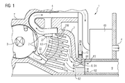
- FIG. 1 shows a section of a switching device 1 with an exemplary Venturi nozzle 8 according to the invention.
- a switching shaft 3 for opening and closing two switch contacts 21, 22 to see.
- the two shown switching contacts 21, 22 form a switching contact pair 2.
- the switching shaft 3 may be formed for opening and closing two or more switching contact pairs 2.
- the switching shaft 3 is connected to a multi-contact.
- the switching contacts 21, 22 are arranged in a quenching chamber designated by the reference numeral 5 for extinguishing an arc LB which is produced during opening.
- the quenching chamber 5 is preferably formed by a housing 7 of the switching device 1.
- the housing 7 is typically made of an insulating material, such as plastic.
- Reference symbol i denotes a current flowing through a current path 4 to be interrupted.
- the current path 4 leaves in the right part of the FIG. 2 the switching device 1 to an electrical connection not shown.
- the current path 4 shown is guided by a current transformer as an overload and / or short-circuit detection member 40. An derived from the current transformer 40 electrical switching signal can then trigger a in the FIG. 1 not shown Switch lock are used when reaching a current threshold.
- a deletion package 6 is furthermore shown in the area of the opened contacts 21, 22, a deletion package 6 is furthermore shown. It has a plurality of quenching plates for cooling the arc plasma.
- the extinguishing chamber 5 opens into a tubular or shaft-shaped gas outlet channel 9 for the escape of a generated when pulling the arc LB overpressure P1.
- the reference numeral DW denotes a pressure wave, which passes through the quenching plates of the quenching packet 6 and then continues into the gas outlet channel 9 when the arc LB is drawn.
- the gas outlet channel 9 has a Venturi nozzle 8, wherein a negative pressure P2 arising in the Venturi nozzle 8 when the gas stream flows through can be detected by means of a pressure sensor 10.
- the pressure sensor 10 is mounted in the mouth region of the gas outlet channel 9.
- the gas outlet channel 9 also has a taper 81. In the narrowest point, that is, the maximum taper, the metrological vacuum decrease takes place by the pressure sensor 10.
- a not further designated measuring port of the pressure sensor 10 projects into the tapered point 81 of the Venturi nozzle 8. Now reaches the negative pressure P2 a predetermined threshold, the pressure sensor 10 can trigger at least indirectly, a mechanical or electrical means connected thereto a switching mechanism 30.
- a inflow element 82 is arranged, which divides the gas outlet channel 9 into a measuring flow channel 91 and into a main flow channel 92.
- the measuring flow channel 91 is provided for the pressure detection according to the invention by means of the pressure sensor 10.
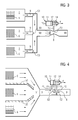
- FIG. 2 shows a first embodiment of the switching device 1.
- the pressure sensor 10 is connected to detect the negative pressure P2 via a pressure connection line 15 to the venturi 8.
- the pressure connection line 15 has a connection piece 17, which is provided for connection to the Venturi nozzle 8.
- the connecting piece 17 furthermore has a pressure compensation element 18, preferably a membrane, for gas-tight connection of the venturi 8 to the pressure sensor 10.
- the pressure sensor 10 is preferably arranged in the region of the switching mechanism 30 of the switching device 1.
- the pressure sensor 10 designed as a pressure-dependent actuating element acts on a triggering mechanism 25 for triggering the switching mechanism 30.
- an actuating slide 14 of the actuating element 10 engages with its pawl-shaped end in a release lever, not shown, the trigger mechanism 25.
- the actuating slide 14 is connected to a piston 12 which is guided in a cylinder 11 of the pressure sensor 10 movable and at least approximately gas-tight.
- the negative pressure P2 produced in the Venturi nozzle 8 now acts directly on the piston 12 of the pressure-dependent actuating element 10.
- switching device 1 is exemplified multipolar, with only one pole can be seen in the present illustration.
- Such a switching device 1 has per pole an extinguishing chamber 5, a gas outlet channel 9 and respectively a pressure sensor 10.
- the respective pressure sensor 10 is connected to a trigger mechanism 25 for triggering the switching mechanism 1 or, as in FIG. 2 already shown connected to a common collecting shaft 20 of the trigger mechanism 25.
- FIG. 3 shows a second embodiment of the switching device 1 in an exemplary three-pole embodiment.
- each pole an extinguishing chamber 5 and a gas outlet channel 9 is present.
- the respective gas outlet channels 9 open into a common gas outlet collecting channel 90, in which in turn a pressure sensor 10 for pressure detection of the negative pressure P2 in the Venturi nozzle 8 is present. It is advantageous in this case that only one (single) pressure sensor is required for joint release of the switching mechanism when a minimum arc power is reached.
- the pressure sensor 10 is designed as a pressure-dependent actuating element with a cylinder 11 and a piston 12. With the piston 12 of the actuating slide 14 is connected for applying a release force F.
- the left pressure chamber of the pressure sensor 10 shown has an opening relative to the ambient pressure P1.
- a negative pressure P2 that is, in the presence of a pressure difference P2-P1
- the piston 12 shown pushes in the release direction to the right.
- the three gas outlet channels 9 shown are each connected via a return flow flap 93 to the common gas outlet collecting channel 90.
- a return flow of a gas stream from one of the extinguishing chambers 5 shown into the respective other extinguishing chambers 5 is prevented.
- the switching device 1 is provided for three-pole shutdown of a 3-phase rotary current and a high arc power in one or in two of the three extinguishing chambers 5 is achieved.
- the return flow flaps 93 By means of the return flow flaps 93, the resulting gas flow flows almost unrestrained and with full volume the gas outlet collecting channel 90th
- FIG. 4 shows a third embodiment of the switching device 1.
- the respective switching contacts 21, 22 are polweise isolated from each other.
- the common quenching chamber 5 and the partition walls 52 are fluidically designed so that they extend to the gas outlet channel 9 and thereby taper.
- all the gas streams preferably run in the direction of a nozzle into the mouth region of the gas outlet channel 9.
- the gas outlet channel 9 is divided by means of a flow-in aid 82 into a measuring flow channel 91 and into a main flow channel 92.
- the pressure-dependent actuating element 10 is connected via two pressure connection lines 15, 16 with the non-tapered region of the gas outlet channel 9 for detecting the overpressure P1 and for detecting the negative pressure P2 with the tapered region of the Venturi nozzle 8.
- the switching device 1 per pole at least two in the closed position of the switching device 1 resiliently against each other depressed switching contacts 21, 22.
- so-called contact springs are typically used.
- the switching contacts 21, 22 are separable by the action of electromagnetic repulsion forces, if one Switching contacts 21, 22 flowing through current i exceeds a certain threshold for current limiting.
- the switching device 1 also has an overload and / or short-circuit detection member 40 for triggering the switching mechanism 30.
Landscapes
- Circuit Breakers (AREA)
- High-Tension Arc-Extinguishing Switches Without Spraying Means (AREA)
Applications Claiming Priority (1)
| Application Number | Priority Date | Filing Date | Title |
|---|---|---|---|
| DE102008005101A DE102008005101A1 (de) | 2008-01-16 | 2008-01-16 | Schaltgerät, insbesondere Leistungsschaltgerät |
Publications (1)
| Publication Number | Publication Date |
|---|---|
| EP2081202A2 true EP2081202A2 (fr) | 2009-07-22 |
Family
ID=40510563
Family Applications (1)
| Application Number | Title | Priority Date | Filing Date |
|---|---|---|---|
| EP09150338A Withdrawn EP2081202A2 (fr) | 2008-01-16 | 2009-01-09 | Appareil de commutation, notamment disjoncteur |
Country Status (4)
| Country | Link |
|---|---|
| US (1) | US8063334B2 (fr) |
| EP (1) | EP2081202A2 (fr) |
| CN (1) | CN101488421B (fr) |
| DE (1) | DE102008005101A1 (fr) |
Cited By (12)
| Publication number | Priority date | Publication date | Assignee | Title |
|---|---|---|---|---|
| FR2950474A1 (fr) * | 2009-09-18 | 2011-03-25 | Schneider Electric Ind Sas | Dispositif de coupure ayant au moins un bloc de coupure unipolaire comportant un pont de contacts et disjoncteur comportant un tel dispositif |
| WO2011033182A3 (fr) * | 2009-09-18 | 2011-05-19 | Schneider Electric Industries Sas | Dispositif de coupure ayant au moins un bloc de coupure unipolaire comportant un pont de contacts et disjoncteur comportant un tel dispositif |
| CN102867711A (zh) * | 2011-07-06 | 2013-01-09 | 上海精益电器厂有限公司 | 万能式断路器触头系统的触头支持结构 |
| FR2986659A1 (fr) * | 2012-02-02 | 2013-08-09 | Schneider Electric Ind Sas | Bloc de coupure unipolaire et dispositif de coupure comportant un tel bloc |
| KR101539832B1 (ko) * | 2009-09-18 | 2015-07-27 | 슈나이더 일렉트릭 인더스트리스 에스에이에스 | 회전 접촉 브리지를 포함하는 단극 컷 오프 유닛, 이러한 유닛을 포함하는 컷 오프 장치, 및 이러한 장치를 포함하는 회로 차단기 |
| CN105185669A (zh) * | 2015-10-16 | 2015-12-23 | 江苏大全凯帆电器股份有限公司 | 断路器气体保护装置 |
| EP2831897B1 (fr) * | 2012-03-28 | 2017-03-01 | Larsen & Toubro Limited | Sytème de contacts amélioré à coupure double pour disjoncteurs à boîtier moulé |
| EP3439004A1 (fr) * | 2017-08-01 | 2019-02-06 | Siemens Aktiengesellschaft | Élément de déclenchement d'un déclencheur par pression, déclencheur par pression doté d'un tel élément de déclenchement et commutateur électrique |
| EP3439005A1 (fr) * | 2017-08-01 | 2019-02-06 | Siemens Aktiengesellschaft | Déclencheur par pression pour un commutateur électrique et commutateur électrique comprenant un tel déclencheur par pression |
| WO2021259585A1 (fr) * | 2020-06-23 | 2021-12-30 | Siemens Aktiengesellschaft | Module de gaz d'échappement pour commutateur électrique, dispositif formé par deux modules de gaz d'échappement de ce type et armoire de commutation comprenant un tel dispositif |
| DE102020207774B4 (de) | 2020-06-23 | 2023-05-11 | Jean Müller GmbH Elektrotechnische Fabrik | Geräteträger mit mindestens einem elektrischen Schalter |
| DE102020207773B4 (de) | 2020-06-23 | 2023-05-11 | Jean Müller GmbH Elektrotechnische Fabrik | Schaltschrank mit mindestens zwei Geräteträgern mit jeweils einem elektrischen Schalter |
Families Citing this family (13)
| Publication number | Priority date | Publication date | Assignee | Title |
|---|---|---|---|---|
| DE102009015126A1 (de) | 2009-03-31 | 2010-10-14 | Siemens Aktiengesellschaft | Auslöser für eine elektrische Schaltanordnung |
| US9953789B2 (en) | 2009-09-18 | 2018-04-24 | Schneider Electric Industries Sas | Single-pole breaking unit comprising a rotary contact bridge, and a switchgear device, and circuit breaker comprising such a unit |
| DE102009056480B4 (de) * | 2009-12-01 | 2011-12-08 | Abb Ag | Installationsschaltgerät mit einer Lichtbogenlöscheinrichtung |
| US8471657B1 (en) * | 2011-12-06 | 2013-06-25 | Eaton Corporation | Trip mechanism and electrical switching apparatus including a trip member pushed by pressure arising from an arc in an arc chamber |
| KR101297515B1 (ko) * | 2012-07-23 | 2013-08-16 | 엘에스산전 주식회사 | 차단기 |
| WO2014170529A1 (fr) * | 2013-04-15 | 2014-10-23 | Abb Oy | Boîtier de commutateur électrique |
| EP3048625B1 (fr) * | 2015-01-23 | 2017-08-16 | ABB S.p.A. | Pôle de commutation basse tension |
| KR102349751B1 (ko) * | 2017-03-21 | 2022-01-11 | 엘에스일렉트릭(주) | 단극차단유닛이 구비된 회로 차단기 |
| KR20180114763A (ko) * | 2017-04-11 | 2018-10-19 | 엘에스산전 주식회사 | 기중 차단기의 아크가스 배출구조 |
| DE102017131442B4 (de) * | 2017-12-29 | 2023-11-23 | Eaton Electrical Ip Gmbh & Co. Kg | Ein- oder mehrpoliger Leistungsschalter und modulares System umfassend einen solchen Leistungsschalter |
| EP3557597B1 (fr) * | 2018-04-20 | 2024-01-17 | ABB S.p.A. | Disjoncteur basse tension |
| DE102019220433B4 (de) * | 2019-12-20 | 2022-03-31 | Siemens Aktiengesellschaft | Rückstellelement und elektrischer Schalter mit solch einem Rückstellelement |
| CN118397781B (zh) * | 2024-04-23 | 2024-10-18 | 深圳市宇波智能股份有限公司 | 一种智能建筑消防用安防报警装置 |
Citations (2)
| Publication number | Priority date | Publication date | Assignee | Title |
|---|---|---|---|---|
| US3631369A (en) | 1970-04-27 | 1971-12-28 | Ite Imperial Corp | Blowoff means for circuit breaker latch |
| EP0455564B1 (fr) | 1990-05-04 | 1995-06-21 | Schneider Electric Sa | Déclencheur instantané d'un disjoncteur |
Family Cites Families (9)
| Publication number | Priority date | Publication date | Assignee | Title |
|---|---|---|---|---|
| US4027125A (en) * | 1975-03-17 | 1977-05-31 | Allis-Chalmers Corporation | Gas insulated circuit breaker |
| JPS53117787A (en) * | 1977-03-24 | 1978-10-14 | Mitsubishi Electric Corp | Switch |
| US4276526A (en) * | 1980-01-28 | 1981-06-30 | General Electric Company | Miniature current limiting circuit breaker |
| DE19601639A1 (de) * | 1996-01-18 | 1997-07-24 | Abb Patent Gmbh | Auslöseeinrichtung für Hoch-, Mittel- oder Niederspannungsschaltanlagen bei Auftreten eines Störlichtbogens |
| DE19816505A1 (de) * | 1998-04-14 | 1999-10-21 | Asea Brown Boveri | Leistungsschalter |
| DE19908575A1 (de) * | 1999-02-27 | 2000-08-31 | Moeller Gmbh | Kontaktsystem mit einer Ausblasvorrichtung |
| JP4376483B2 (ja) * | 1999-12-02 | 2009-12-02 | 三菱電機株式会社 | 回路遮断器 |
| DE20215082U1 (de) * | 2002-10-01 | 2002-11-28 | Schwelm Anlagenbau GmbH, 58332 Schwelm | Durchflußsensor zur Erfassung der Rückführgasmenge an einer Kraftstoff-Tankeinrichtung |
| US7313964B2 (en) * | 2004-05-18 | 2008-01-01 | Jennings Technology | Method and apparatus for the detection of high pressure conditions in a vacuum-type electrical device |
-
2008
- 2008-01-16 DE DE102008005101A patent/DE102008005101A1/de not_active Withdrawn
-
2009
- 2009-01-09 EP EP09150338A patent/EP2081202A2/fr not_active Withdrawn
- 2009-01-14 US US12/319,000 patent/US8063334B2/en not_active Expired - Fee Related
- 2009-01-16 CN CN2009100052217A patent/CN101488421B/zh not_active Expired - Fee Related
Patent Citations (3)
| Publication number | Priority date | Publication date | Assignee | Title |
|---|---|---|---|---|
| US3631369A (en) | 1970-04-27 | 1971-12-28 | Ite Imperial Corp | Blowoff means for circuit breaker latch |
| EP0455564B1 (fr) | 1990-05-04 | 1995-06-21 | Schneider Electric Sa | Déclencheur instantané d'un disjoncteur |
| DE69110540T2 (de) | 1990-05-04 | 1996-02-29 | Schneider Electric Sa | Momentauslöser für einen Schalter. |
Cited By (18)
| Publication number | Priority date | Publication date | Assignee | Title |
|---|---|---|---|---|
| FR2950474A1 (fr) * | 2009-09-18 | 2011-03-25 | Schneider Electric Ind Sas | Dispositif de coupure ayant au moins un bloc de coupure unipolaire comportant un pont de contacts et disjoncteur comportant un tel dispositif |
| WO2011033182A3 (fr) * | 2009-09-18 | 2011-05-19 | Schneider Electric Industries Sas | Dispositif de coupure ayant au moins un bloc de coupure unipolaire comportant un pont de contacts et disjoncteur comportant un tel dispositif |
| RU2556240C2 (ru) * | 2009-09-18 | 2015-07-10 | Шнейдер Электрик Эндюстри Сас | Коммутационное устройство, имеющее, по меньшей мере, один однополюсной отключающий блок, содержащий контактный мостик, и прерыватель цепи, содержащий одно такое устройство |
| KR101539832B1 (ko) * | 2009-09-18 | 2015-07-27 | 슈나이더 일렉트릭 인더스트리스 에스에이에스 | 회전 접촉 브리지를 포함하는 단극 컷 오프 유닛, 이러한 유닛을 포함하는 컷 오프 장치, 및 이러한 장치를 포함하는 회로 차단기 |
| US9159508B2 (en) | 2009-09-18 | 2015-10-13 | Schneider Electric Industries Sas | Switchgear device having at least one single-pole breaking unit comprising a contact bridge and circuit breaker comprising one such device |
| CN102867711A (zh) * | 2011-07-06 | 2013-01-09 | 上海精益电器厂有限公司 | 万能式断路器触头系统的触头支持结构 |
| FR2986659A1 (fr) * | 2012-02-02 | 2013-08-09 | Schneider Electric Ind Sas | Bloc de coupure unipolaire et dispositif de coupure comportant un tel bloc |
| EP2831897B1 (fr) * | 2012-03-28 | 2017-03-01 | Larsen & Toubro Limited | Sytème de contacts amélioré à coupure double pour disjoncteurs à boîtier moulé |
| CN105185669A (zh) * | 2015-10-16 | 2015-12-23 | 江苏大全凯帆电器股份有限公司 | 断路器气体保护装置 |
| EP3439004A1 (fr) * | 2017-08-01 | 2019-02-06 | Siemens Aktiengesellschaft | Élément de déclenchement d'un déclencheur par pression, déclencheur par pression doté d'un tel élément de déclenchement et commutateur électrique |
| EP3439005A1 (fr) * | 2017-08-01 | 2019-02-06 | Siemens Aktiengesellschaft | Déclencheur par pression pour un commutateur électrique et commutateur électrique comprenant un tel déclencheur par pression |
| WO2019025361A1 (fr) * | 2017-08-01 | 2019-02-07 | Siemens Aktiengesellschaft | Élément déclencheur d'un déclencheur de pression, déclencheur de pression doté d'un tel élément déclencheur et commutateur électrique |
| DE102018211995B4 (de) * | 2017-08-01 | 2020-12-10 | Siemens Aktiengesellschaft | Druckauslöser für einen elektrischen Schalter und elektrischer Schalter mit solch einem Druckauslöser |
| US10971316B2 (en) | 2017-08-01 | 2021-04-06 | Siemens Aktiengesellschaft | Pressure trip unit for an electrical switch and electrical switch with such a pressure trip unit |
| US11056297B2 (en) | 2017-08-01 | 2021-07-06 | Siemens Aktiengesellschaft | Trigger element of a pressure trigger, pressure trigger with a trigger element of this kind and electric switch |
| WO2021259585A1 (fr) * | 2020-06-23 | 2021-12-30 | Siemens Aktiengesellschaft | Module de gaz d'échappement pour commutateur électrique, dispositif formé par deux modules de gaz d'échappement de ce type et armoire de commutation comprenant un tel dispositif |
| DE102020207774B4 (de) | 2020-06-23 | 2023-05-11 | Jean Müller GmbH Elektrotechnische Fabrik | Geräteträger mit mindestens einem elektrischen Schalter |
| DE102020207773B4 (de) | 2020-06-23 | 2023-05-11 | Jean Müller GmbH Elektrotechnische Fabrik | Schaltschrank mit mindestens zwei Geräteträgern mit jeweils einem elektrischen Schalter |
Also Published As
| Publication number | Publication date |
|---|---|
| DE102008005101A1 (de) | 2009-07-23 |
| US8063334B2 (en) | 2011-11-22 |
| CN101488421B (zh) | 2013-06-19 |
| CN101488421A (zh) | 2009-07-22 |
| US20090194510A1 (en) | 2009-08-06 |
Similar Documents
| Publication | Publication Date | Title |
|---|---|---|
| EP2081202A2 (fr) | Appareil de commutation, notamment disjoncteur | |
| DE69110540T2 (de) | Momentauslöser für einen Schalter. | |
| WO2008080858A2 (fr) | Disjoncteur à gaz comprimé comprenant une ouverture d'écoulement radiale | |
| DE102009015126A1 (de) | Auslöser für eine elektrische Schaltanordnung | |
| DE102018211995B4 (de) | Druckauslöser für einen elektrischen Schalter und elektrischer Schalter mit solch einem Druckauslöser | |
| DE112011102204T5 (de) | Überlastrelaisschalter ohne Federn | |
| DE102008026813B4 (de) | Elektrischer selektiver Selbstschalter | |
| DE102011077359A1 (de) | Auslöser für eine elektrische Schaltanordnung | |
| DE102009015222A1 (de) | Auslöser für eine elektrische Schaltanordnung | |
| WO2001069637A1 (fr) | Declencheur combine pour un disjoncteur | |
| EP2704171A1 (fr) | Unité à curseur de contact pour une unité de commutation, notamment pour un disjoncteur | |
| EP3186864B1 (fr) | Déclenchement d'un système de protection contre des arcs électriques parasites | |
| DE102009010900A1 (de) | Auslöser für eine elektrische Schaltanordnung | |
| DE102012005031A1 (de) | Installationsschaltgerät | |
| DE102017131442B4 (de) | Ein- oder mehrpoliger Leistungsschalter und modulares System umfassend einen solchen Leistungsschalter | |
| DE102009010227A1 (de) | Auslöser für eine elektrische Schaltanordnung | |
| EP3439005A1 (fr) | Déclencheur par pression pour un commutateur électrique et commutateur électrique comprenant un tel déclencheur par pression | |
| DE102008049554A1 (de) | Elektrischer Schalter | |
| EP3293751B1 (fr) | Mécanisme de commande d'un appareil de commutation basse tension | |
| DE102008049998A1 (de) | Elektrischer Schalter mit Druckerfassungsglied | |
| DE102019220433B4 (de) | Rückstellelement und elektrischer Schalter mit solch einem Rückstellelement | |
| DE102006036194A1 (de) | Schaltvorrichtung mit Schaltstellenpaar | |
| DE102010053229A1 (de) | Installationsschaltgerät | |
| DE102009010229A1 (de) | Auslöser für eine elektrische Schaltanordnung | |
| WO2007087761A1 (fr) | Interrupteur de puissance |
Legal Events
| Date | Code | Title | Description |
|---|---|---|---|
| PUAI | Public reference made under article 153(3) epc to a published international application that has entered the european phase |
Free format text: ORIGINAL CODE: 0009012 |
|
| AK | Designated contracting states |
Kind code of ref document: A2 Designated state(s): AT BE BG CH CY CZ DE DK EE ES FI FR GB GR HR HU IE IS IT LI LT LU LV MC MK MT NL NO PL PT RO SE SI SK TR |
|
| AX | Request for extension of the european patent |
Extension state: AL BA RS |
|
| STAA | Information on the status of an ep patent application or granted ep patent |
Free format text: STATUS: THE APPLICATION IS DEEMED TO BE WITHDRAWN |
|
| 18D | Application deemed to be withdrawn |
Effective date: 20120801 |