EP2078819A1 - Stepladder with folding platform and separating support legs - Google Patents
Stepladder with folding platform and separating support legs Download PDFInfo
- Publication number
- EP2078819A1 EP2078819A1 EP08356152A EP08356152A EP2078819A1 EP 2078819 A1 EP2078819 A1 EP 2078819A1 EP 08356152 A EP08356152 A EP 08356152A EP 08356152 A EP08356152 A EP 08356152A EP 2078819 A1 EP2078819 A1 EP 2078819A1
- Authority
- EP
- European Patent Office
- Prior art keywords
- platform
- stepladder
- support legs
- folding
- articulated
- Prior art date
- Legal status (The legal status is an assumption and is not a legal conclusion. Google has not performed a legal analysis and makes no representation as to the accuracy of the status listed.)
- Granted
Links
- 230000006641 stabilisation Effects 0.000 claims description 3
- 238000011105 stabilization Methods 0.000 claims description 2
- 125000006850 spacer group Chemical group 0.000 abstract description 3
- 230000000087 stabilizing effect Effects 0.000 description 4
- 238000012423 maintenance Methods 0.000 description 2
- 238000013459 approach Methods 0.000 description 1
- 230000033228 biological regulation Effects 0.000 description 1
- 230000009194 climbing Effects 0.000 description 1
- 238000000926 separation method Methods 0.000 description 1
- 239000002689 soil Substances 0.000 description 1
- 239000003381 stabilizer Substances 0.000 description 1
- 230000001052 transient effect Effects 0.000 description 1
Images


Classifications
-
- E—FIXED CONSTRUCTIONS
- E06—DOORS, WINDOWS, SHUTTERS, OR ROLLER BLINDS IN GENERAL; LADDERS
- E06C—LADDERS
- E06C1/00—Ladders in general
- E06C1/02—Ladders in general with rigid longitudinal member or members
- E06C1/38—Special constructions of ladders, e.g. ladders with more or less than two longitudinal members, ladders with movable rungs or other treads, longitudinally-foldable ladders
- E06C1/39—Ladders having platforms; Ladders changeable into platforms
- E06C1/393—Ladders having platforms foldable with the ladder
-
- E—FIXED CONSTRUCTIONS
- E06—DOORS, WINDOWS, SHUTTERS, OR ROLLER BLINDS IN GENERAL; LADDERS
- E06C—LADDERS
- E06C1/00—Ladders in general
- E06C1/02—Ladders in general with rigid longitudinal member or members
- E06C1/14—Ladders capable of standing by themselves
- E06C1/16—Ladders capable of standing by themselves with hinged struts which rest on the ground
- E06C1/20—Ladders capable of standing by themselves with hinged struts which rest on the ground with supporting struts formed as poles
- E06C1/22—Ladders capable of standing by themselves with hinged struts which rest on the ground with supporting struts formed as poles with extensible, e.g. telescopic, ladder parts or struts
-
- E—FIXED CONSTRUCTIONS
- E06—DOORS, WINDOWS, SHUTTERS, OR ROLLER BLINDS IN GENERAL; LADDERS
- E06C—LADDERS
- E06C7/00—Component parts, supporting parts, or accessories
- E06C7/18—Devices for preventing persons from falling
- E06C7/181—Additional gripping devices, e.g. handrails
- E06C7/182—Additional gripping devices, e.g. handrails situated at the top of the ladder
-
- E—FIXED CONSTRUCTIONS
- E06—DOORS, WINDOWS, SHUTTERS, OR ROLLER BLINDS IN GENERAL; LADDERS
- E06C—LADDERS
- E06C7/00—Component parts, supporting parts, or accessories
- E06C7/42—Ladder feet; Supports therefor
- E06C7/423—Ladder stabilising struts
Definitions
- the invention relates to a stepladder with folding platform and removable support legs.
- step ladders whose steps are deeper than the rungs of a ladder and provide a better grip of the user.
- this user is in support on the last step, its lateral stability remains uncertain because it depends on the position of his body relative to the support polygon of the stepladder, and also the energy it provides with them. arm and torso in relation to this stool.
- each lateral leg is articulated on one of the uprights of the climb plan and is deployed manually after the balancing plan has been removed from the climb plan, ie after the step ladder has been brought from its position storage and transport at its position of use.
- the lateral spacing of each stabilizing leg is limited by pulling the connecting to the corresponding amount of the climb plan, this tie being constituted by a chain or other flexible link.
- this arrangement improves the stability of the stepladder in working position, it however requires human intervention to spread the stabilizing legs and adjust the length to suit the spacing and configuration or the flatness of the soil.
- the lift polygon is reduced to the surface between the rear plane of the plane and the front support plane and the stability of the stool is that of traditional stools, so that, to avoid falls, the user must not make ample movements overflowing the polygon delimited by the sole feet of the stool.
- Sliding ladders are also known whose lower climbing plane is equipped with two support legs hinged to the vertices of its uprights and to be manually deployed forwardly and laterally to increase the lifting polygon and stability.
- the quality of the stability obtained depends on the rigor of the human intervention required for this deployment.
- the object of the present invention is to provide a stepladder which eliminates the influence of human intervention during the setting in working conditions of a stepladder, and which is adapted to the new regulations requiring to provide, at the top of the equipment, a platform and guardrail improving the safety of the operator having to work at height.
- the front support plane of the traditional stepladder is replaced by the two articulated legs which add to their stabilization function that of support of the rear climb plan and which, for the rest of the description, are called support legs.
- the movement that the operator must perform to bring the stepladder from its storage position to its position of use causes , by the spreading arms, the sliding down of the collars on the legs, sliding causing, first, the spacing of them to the front, under the control of the tie rods, then their lateral spacing by the action of arm spreaders, and more precisely by the spacing of these arms for compensate for the lengthening of the virtual sides in each of the leg control triangles.
- the platform carries two lower fittings whose openings are each traversed by one of the spreader arms, and ensure, in the spacing and folding phases of the legs, the maintenance of each arm in a plan parallel to that of the platform.
- each of the support legs comprises means for adjusting its length to compensate for a difference in height of the bearing surface to maintain the platform in a substantially horizontal position.
- This arrangement is particularly interesting for step stools used to perform outdoor work from unevenly flat floors.
- these level compensators make it possible to erase the influence of at least one stair step on the horizontality of the platform and thus to maintain a good stability at the stool.
- Figures 1 and 2 are views in perspective, from the front and in elevation, of the stepladder when it is, respectively, and in the storage position and in the position of use;
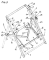
- Figure 3 is a partial view, in perspective from below and on an enlarged scale, when the stepladder is in use position.
- Figures 4, 5 and 6 are perspective views, from the front and under, when the step stool is, respectively, in the storage position, being deployed and deployed.
- FIG. 7 is a perspective view from the rear of another embodiment in which each of the support legs is provided with a level compensator
- Figures 8 and 9 are views, respectively, of side elevation with partial and partial sectional section along 9-9 of figure 8 , showing a leg on an enlarged scale.
- this stool comprises a rise plane M composed of uprights 2 and bars 3 which extend vertically to a height less than the uprights and which, in the embodiment shown, extend substantially at half height.
- a folding platform 4 is articulated around a horizontal axis and, in particular, on the last bar 3a. The articulation is achieved by sockets 5, or equivalent means, disposed under the rear edge of the platform and so that it can be deployed forward.
- the stepladder also comprises two support legs 6 articulated each at the top of one of the uprights 2, via a hinge 7, multidirectional or with several degrees of freedom. On each leg can slide a collar 8 or other equivalent member, whose travel downward is limited by a stop ring 11. This ring defines the horizontal positioning of the platform and ensures the limitation of the spacing of the legs 6.
- Each collar 8 carries a hinge 9 by which it is articulated at the end of a lateral tie rod 10, constituted by a rigid lever.
- the other end of each pulling is articulated on the upright 2 of the rise plane M by a hinge 12, multidirectional or with several degrees of freedom.
- the various figures show that this articulation is disposed above the bar 3a forming the articulation of the platform.
- the platform 4 is associated with a collapsible guard 13 whose lateral branches 14 are articulated, near their front ends and by pins 15, to the vertices of the uprights 2.
- the rear end of each branches 14 of the bodyguard are connected, by a connecting rod 16, to the rear end of the platform 4.
- the lower end of each connecting rod 16 is connected to the platform by a hinge 17, while its upper end is connected, by a hinge 18, to a collar 19 slidably mounted on the corresponding branch 14.
- each collar is limited and takes place between two locking notches, respectively posterior 20a and anterior 20b, visible to the figures 3 , 5 and 6 , and defining, the first, the normal position of the guardrail, and, the second, a transient position facilitating the access of the user to the platform 4.
- the stepladder also comprises means which ensure the automatic spacing of the legs when it is placed in the position of use.
- These means comprise two spreader arms 22 which are arranged under the platform 4. figure 3 the posterior ends of the arms 22 are articulated on a common pivot 23, orthogonal to the platform and protruding from its bottom, while their anterior ends are connected to one of the two collars 8 by a hinge 24.
- the pivot 23 is disposed substantially in the middle of the width of the platform 4 and between the half and the back third of its length.
- Each of the spreader arms 22 passes through an opening 25a formed in a fitting 25 attached under the plate 4 and near each of its front angles.
- the edges of each opening cooperate with the corresponding arm 22 to guide it transversely with respect to the platform, so that its movements take place in a plane parallel to that of the platform, regardless of the position of this platform relative to the plane. climb that carries it.
- the automatic spacing means comprise an arm 22 and a tie rod 10 which are articulated on the same collar 8, and form two sides of a deformable triangle whose third side, shown in FIG. C3 at the Figure 3 is virtual and extends between the pivot 23 and the hinge 12 of the tie rod on the upright 2.
- the legs 6 are arranged against the front face of this plane and between the uprights 2.
- the collars 8 are at the highest on the legs, in relation to the length of the tie rods 10 which extend vertically upwards and between the uprights 2 from the joints 12.
- the spreader arms 22 are entirely between the uprights 2 and define an angle a .
- the use position of the ladder is made by manually pivoting the platform 4 downwards and forwards, as shown by the arrow 41 to the figure 5 .
- the arms 22 are driven by the platform 4 and, by the collars 8 and tie rods 10, force the legs 6 to pivot about their joints 7 away from the uprights 2.
- the arms 22 move apart, as shown by the angle b at the figure 6 , Greater than that of a figure 4 .
- the collars 8 slide on the legs, they communicate to them a movement of spacing towards the front and a movement of separation towards the sides until the end of tilting platform 4.
- the movements of the spreader arms 22 are controlled by the movement of the pivot 23 which, when lowered, moves away from the joints 12 and increases the length of the virtual sides C3 of each of the leg control triangles 6 .
- the spacer means not only act automatically, without the need for human intervention in addition to that necessary for the deployment of the platform, but give the support legs a gap of EM value, visible figure 2 , much higher than the starting value Em, visible figure 4 , by improving the ground support surface and the stability of the stepladder.
- stepladder When the stepladder is in the position of use, access to its platform is facilitated by temporarily pushing the rods 16 forward, by sliding their collars 19 to 20b wedges 20b. As soon as the user is on the platform, he is encouraged to bring the connecting rods back locked position, by the inclination given to the guard rail by these rods.
- each leg includes means for adjusting its length to compensate for a difference in height of the bearing surface to maintain the platform 4 in a substantially horizontal position. More precisely, each leg 6 is formed by two telescopic elements, upper 6a and lower 6b respectively. The upper one 6a serves as a slide on the collar 8 carrying the hinges, respectively, 9 of the tie rod 10 and 24 of the corresponding spacer arm.
- This element 6a carries at its lower end the abutment ring 11, limiting the downward stroke of the collar 8. It also comprises, above this ring, a longitudinal groove 30 into which notches 31, staggered longitudinally, c ' that is, distributed along the element with a regular pitch and over the entire length of adjustment.
- the pitch is of the order of 20 to 25 millimeters for an adjustment stroke of the order of 160 to 200 millimeters measured on either side of a central position, considered optimal.
- the figure 8 shows that the notches 31 go upwardly leaving the groove 30 to be self-locking by the sole mass of the stool and, of course, by the mass of the stepladder and the user.
- the lower element 6b is tubular, like the one 6a in which it is slidably mounted. Near its upper end the lower element 6b is traversed by a rod 32 projecting radially on one side to form a finger 32a. It is slidably mounted in the groove 30 and is able to penetrate any of the locking notches 31.
- the figure 9 shows that the rod 32 of the lower element 6b is connected by elastic return means, such as a tension spring 33, to another rod 34 passing through the upper element 6a.
- elastic return means such as a tension spring 33
- the lower element 6a is constantly stressed by a tensile force T which tends to return it into the upper element 6a and, especially, to press the finger 32a into its notch 31, as shown figure 8 .
- This height compensation can also be used to position the stepladder on a stairway, to absorb the difference in level of at least one step 35 as shown in FIG. figure 7 .
Abstract
Description
L'invention concerne un escabeau avec plateforme rabattable et jambes d'appui écartables.The invention relates to a stepladder with folding platform and removable support legs.
Pour effectuer des travaux d'entretien à faible hauteur, et par exemple pour changer des éléments d'éclairage dans des ateliers, éléments situés à une hauteur comprise entre 2.5 mètres à 4 mètres, il est courant d'avoir recours à des escabeaux dont les marches sont plus profondes que les barreaux d'une échelle et procurent une meilleure tenue de l'utilisateur. Toutefois, quand cet utilisateur est en appui sur la dernière marche, sa stabilité latérale reste incertaine car elle dépend de la position de son corps par rapport au polygone de sustentation de l'escabeau, et aussi de l'énergie qu'il fournit avec les bras et le torse par rapport à cet escabeau.In order to carry out maintenance work at low height, and for example to change lighting elements in workshops, elements located at a height of between 2.5 meters and 4 meters, it is common practice to use step ladders whose steps are deeper than the rungs of a ladder and provide a better grip of the user. However, when this user is in support on the last step, its lateral stability remains uncertain because it depends on the position of his body relative to the support polygon of the stepladder, and also the energy it provides with them. arm and torso in relation to this stool.
Pour améliorer cette stabilité, le document
Si cet aménagement améliore la stabilité de l'escabeau en position de travail, il impose cependant une intervention humaine pour écarter les jambes stabilisatrices et en régler la longueur pour les adapter à l'écartement et à la configuration ou la planéité du sol. Ainsi, si l'utilisateur ne déploie pas les jambes de stabilisation, le polygone de sustentation est réduit à la surface comprise entre le plan de montée arrière et le plan d'appui avant et la stabilité de l'escabeau est celle des escabeaux traditionnels, de sorte que, pour éviter les chutes, l'utilisateur ne doit pas faire des mouvements amples débordant du polygone délimité par les seuls pieds de l'escabeau.If this arrangement improves the stability of the stepladder in working position, it however requires human intervention to spread the stabilizing legs and adjust the length to suit the spacing and configuration or the flatness of the soil. Thus, if the user does not deploy the stabilizing legs, the lift polygon is reduced to the surface between the rear plane of the plane and the front support plane and the stability of the stool is that of traditional stools, so that, to avoid falls, the user must not make ample movements overflowing the polygon delimited by the sole feet of the stool.
On connait aussi des échelles coulissantes dont le plan de montée inférieur est équipé de deux jambes d'appui articulées aux sommets de ses montants et devant être déployées manuellement vers l'avant et latéralement pour augmenter le polygone de sustentation et la stabilité. Là aussi, la qualité de la stabilité obtenue dépend de la rigueur de l'intervention humaine nécessaire à ce déploiement.Sliding ladders are also known whose lower climbing plane is equipped with two support legs hinged to the vertices of its uprights and to be manually deployed forwardly and laterally to increase the lifting polygon and stability. Here again, the quality of the stability obtained depends on the rigor of the human intervention required for this deployment.
La présente invention à pour objet de fournir un escabeau qui élimine l'influence de l'intervention humaine lors de la mise en conditions de travail d'un escabeau, et qui soit adapté aux nouvelles réglementations exigeant de prévoir, au sommet de l'équipement, une plateforme et un garde corps améliorant la sécurité de l'opérateur devant travailler en hauteur.The object of the present invention is to provide a stepladder which eliminates the influence of human intervention during the setting in working conditions of a stepladder, and which is adapted to the new regulations requiring to provide, at the top of the equipment, a platform and guardrail improving the safety of the operator having to work at height.
Elle concerne plus particulièrement un escabeau comprenant :
- un plan de montée arrière dont les montants sont reliés par des marches ou par des barreaux,
- une plateforme articulée sur les montants du plan de montée avec possibilité de saillir vers l'avant ou d'être rabattue contre le plan de montée,
- deux jambes d'appui, articulées près du sommet de chacun des deux montants par des articulations leur permettant d'occuper une position de rangement, dans laquelle elles sont contre les montants, et une position de stabilisation, dans laquelle elles sont écartées de ces montants, sur le coté et vers l'avant,
- et des tirants contrôlant l'écartement des jambes, chaque tirant étant disposé entre la jambe et le montant sur lequel celle-ci est articulée.
- un bras écarteur disposé sous la plateforme articulée et dont une extrémité est articulée sur un pivot, orthogonal au fond de cette plateforme et commun avec l'autre bras, alors que l'autre extrémité est articulée sur un collier monté coulissant sur la jambe correspondante,
- le tirant correspondant, dont une extrémité est liée au collier précité par une articulation, alors que son autre extrémité est liée à un montant par une articulation disposée au dessus de l'articulation de la plateforme,
ces deux éléments, bras écarteur et tirant, constituant deux des cotés d'un triangle dont la déformation du troisième coté, formé entre le pivot et l'articulation du tirant sur le montant, modifie la position du collier sur la jambe.
- a rear climb plan whose amounts are connected by steps or bars,
- a platform articulated on the uprights of the plan of climb with possibility to project forward or to be folded against the plan of rise,
- two support legs, articulated near the top of each of the two uprights by articulations allowing them to occupy a storage position, in which they are against the uprights, and a stabilizing position, in which they are spaced from these amounts , on the side and towards the front,
- and tie rods controlling the spacing of the legs, each tie being disposed between the leg and the amount on which it is hinged.
- a spreader arm disposed under the articulated platform and one end of which is articulated on a pivot, orthogonal to the bottom of this platform and common with the other arm, while the other end is hinged to a collar slidably mounted on the corresponding leg,
- the corresponding tie rod, one end of which is connected to the aforementioned collar by a hinge, while its other end is connected to an upright by a hinge disposed above the hinge of the platform,
these two elements, spreader arm and pulling, constituting two sides of a triangle whose deformation of the third side, formed between the pivot and the articulation of the pulling on the upright, modifies the position of the collar on the leg.
Il faut remarquer que dans cet agencement, le plan d'appui avant de l'escabeau traditionnel est remplacé par les deux jambes articulées qui ajoutent à leur fonction de stabilisation celle d'appui du plan de montée arrière et qui, pour la suite de la description, sont appelées jambes d'appui.It should be noted that in this arrangement, the front support plane of the traditional stepladder is replaced by the two articulated legs which add to their stabilization function that of support of the rear climb plan and which, for the rest of the description, are called support legs.
Grace à cet aménagement, le mouvement que l'opérateur doit effectuer pour amener l'escabeau de sa position de rangement à sa position d'utilisation, et qui consiste à faire pivoter la plateforme pour la déployer en même temps que son garde corps, provoque, par les bras écarteurs, le coulissement vers le bas des colliers sur les jambes, coulissement provoquant, d'abord, l'écartement de celles ci vers l'avant, sous le contrôle des tirants, puis leur écartement latéral par l'action des bras écarteurs, et plus précisément par l'écartement de ces bras pour compenser l'allongement des cotés virtuels dans chacun des triangles de commande des jambes.Thanks to this arrangement, the movement that the operator must perform to bring the stepladder from its storage position to its position of use, and which consists in pivoting the platform to deploy it at the same time as its guard rail, causes , by the spreading arms, the sliding down of the collars on the legs, sliding causing, first, the spacing of them to the front, under the control of the tie rods, then their lateral spacing by the action of arm spreaders, and more precisely by the spacing of these arms for compensate for the lengthening of the virtual sides in each of the leg control triangles.
Il en résulte que ces jambes s'écartent automatiquement et prennent appui de part et d'autre et en avant des pieds du plan de montée, en augmentant ainsi la surface d'appui au sol et la stabilité de l'escabeau.As a result, these legs deviate automatically and are supported on both sides and in front of the feet of the plane of rise, thus increasing the ground support surface and the stability of the stool.
Dans une forme d'exécution de l'invention, la plateforme porte deux ferrures inférieures dont les ouvertures sont traversées chacune par l'un des bras écarteurs, et assurent, dans les phases écartement et de repliement des jambes, le maintien de chaque bras dans un plan parallèle à celui de la plateforme.In one embodiment of the invention, the platform carries two lower fittings whose openings are each traversed by one of the spreader arms, and ensure, in the spacing and folding phases of the legs, the maintenance of each arm in a plan parallel to that of the platform.
Cela améliore la fiabilité des moyens d'écartement des bras et la régularité des mouvements.This improves the reliability of the means of spreading the arms and the regularity of the movements.
Dans une forme d'exécution, chacune des jambes d'appui comprend, des moyens de réglage de sa longueur permettant de compenser un dénivelé de la surface d'appui pour maintenir la plateforme dans une position sensiblement horizontale.In one embodiment, each of the support legs comprises means for adjusting its length to compensate for a difference in height of the bearing surface to maintain the platform in a substantially horizontal position.
Cet aménagement est particulièrement intéressant pour les escabeaux utilisés pour effectuer des travaux extérieurs à partir de sols ayant une planéité irégulière. A l'intérieur d'un local, ces compensateurs de niveau permettent d'effacer l'influence d'au moins une marche d'escalier sur l'horizontalité de la plateforme et ainsi de conserver une bonne stabilité à l'escabeau.This arrangement is particularly interesting for step stools used to perform outdoor work from unevenly flat floors. Inside a room, these level compensators make it possible to erase the influence of at least one stair step on the horizontality of the platform and thus to maintain a good stability at the stool.
D'autre caractéristiques et avantages ressortiront de la description qui suit, en référence au dessin schématique annexé, représentant une forme d'exécution de cet escabeau.Other features and advantages will become apparent from the description which follows, with reference to the attached schematic drawing, showing an embodiment of this stool.
Comme montré sur les différentes figures, cet escabeau comprend un plan de montée M composée de montants 2 et de barreaux 3 qui s'étendent verticalement sur une hauteur moindre que les montants et qui, dans la forme d'exécution représentée, s'étendent sensiblement à mi hauteur. Une plateforme rabattable 4 est articulée autour d'un axe horizontal et, en particulier, sur le dernier barreau 3a. L'articulation est réalisée par des douilles 5, ou par des moyens équivalents, disposées sous le bord postérieur de la plateforme et de manière que celle ci puisse se déployer vers l'avant.As shown in the various figures, this stool comprises a rise plane M composed of
L'escabeau comprend aussi deux jambes d'appui 6 articulée chacune au sommet de l'un des montants 2, par l'intermédiaire d'une articulation 7, multidirectionnelle ou à plusieurs degrés de liberté. Sur chaque jambe peut coulisser un collier 8 ou autre organe équivalent, dont la course vers le bas est limitée par une bague de butée 11. Cette bague définit le positionnement horizontal de la plateforme et assure la limitation de l'écartement des jambes 6.The stepladder also comprises two
Chaque collier 8 porte une articulation 9 par laquelle il est articulé à l'extrémité d'un tirant latéral 10, constitué par un levier rigide. L'autre extrémité de chaque tirant est articulée sur le montant 2 du plan de montée M par une articulation 12, multidirectionnelle ou à plusieurs degrés de liberté. Les diverses figures montrent que cette articulation est disposée au dessus du barreau 3a formant l'articulation de la plateforme.Each
Dans la forme d'exécution représentée, la plateforme 4 est associée à un garde corps repliable 13 dont les branches latérales 14 sont articulées, près de leurs extrémités avant et par des axes 15, aux sommets des montants 2. L'extrémité postérieure de chacune des branches 14 du garde corps est reliée, par une bielle 16, à l'extrémité postérieure de la plateforme 4. L'extrémité inférieure de chaque bielle 16 est liée à la plateforme par une articulation 17, tandis que son extrémité supérieure est liée, par une articulation 18, à un collier 19 monté coulissant sur la branche 14 correspondante. Le coulissement de chaque collier est limité et s'effectue entre deux crans de blocage, respectivement postérieur 20a et antérieur 20b, visibles aux
Selon l'invention, l'escabeau comprend aussi des moyens qui assurent l'écartement automatique des jambes lors de sa mise en position d'utilisation. Ces moyens comprennent deux bras écarteurs 22 qui sont disposés sous la plateforme 4. Comme le montre bien la
Chacun des bras écarteur 22 traverse une ouverture 25a formée dans une ferrure 25 rapportée sous la platine 4 et près de chacun de ses angles antérieurs. Les bords de chaque ouverture coopèrent avec le bras 22 correspondant pour le guider transversalement par rapport à la plateforme, afin que ses mouvements s'effectuent dans un plan parallèle à celui de la plateforme, quelle que soit la position de cette plateforme par rapport au plan de montée qui la porte.Each of the
Il ressort de cette description que pour chaque jambe 6 les moyens d'écartement automatique comprennent un bras 22 et un tirant 10 qui sont articulés sur le même collier 8, et forment deux des cotés d'un triangle déformable dont le troisième coté, représentée en C3 à la
Comme montré aux
La mise en position d'utilisation de l'escabeau s'effectue en faisant pivoter manuellement la plateforme 4 vers le bas et vers l'avant, comme montré par la flèche 41 à la
Durant le basculement de la plateforme 4, les mouvements des bras écarteurs 22 sont contrôlés par le mouvement du pivot 23 qui en s'abaissant s'eloigne des articulations 12 et augmente la longueur des cotés virtuels C3 de chacun des triangles de commande des jambes 6.During the tilting of the platform 4, the movements of the
Le pivotement s'arrête quand les colliers 8 viennent en butée sur les bagues 11, comme montré aux
II ressort de ce qui précède que les moyens d'écartement, non seulement agissent automatiquement, sans besoin d'une intervention humaine s'ajoutant à celle nécessaire au déploiement de la plateforme, mais donnent aux jambes d'appui un écartement de valeur EM, visible
Quand l'escabeau est en position d'utilisation, l'accès à sa plateforme est facilité en repoussant temporairement les bielles 16 vers l'avant, par coulissement de leur colliers 19 jusqu'aux crans de calage 20b. Dès que l'utilisateur est sur la plateforme, il est incité à ramener les bielles en position verrouillée arrière, par l'inclinaison donnée au garde corps par ces bielles.When the stepladder is in the position of use, access to its platform is facilitated by temporarily pushing the
Les opérations inverses sont effectuées pour permettre à l'utilisateur de quitter la plateforme.Inverse operations are performed to allow the user to leave the platform.
Le repliage ultérieur de l'escabeau ne nécessite qu'une opération manuelle de rabattement de la plateforme contre le plan M, puisque par le jeu des bras 22, tirants 10 et colliers 8, les jambes 6 reviennent automatiquement en position de rangement contre le plan M et entre les montants 2.The subsequent folding of the stool only requires a manual operation of folding the platform against the plane M, since by the play of the
Dans la forme d'exécution montrée aux
Cet élément 6a porte à son extrémité inférieure la bague de butée 11, limitant la course vers le bas du collier 8. Il comporte aussi, au dessus de cette bague, une rainure longitudinale 30 dans laquelle débouchent des crans 31, étagés longitudinalement, c'est-à-dire répartis le long de l'élément avec un pas régulier et sur toute la longueur de réglage. A titre d'exemple, le pas est de l'ordre de 20 à 25 millimètres pour une course de réglage de l'ordre de 160 à 200 millimètres mesurée de part et d'autre d'une position centrale, considérée comme optimale.This
La
L'élément inférieur 6b est tubulaire, comme celui 6a dans lequel il est monté coulissant. Près de son extrémité supérieure l'élément inférieur 6b est traversé par une tige 32 saillant radialement d'un coté pour former un doigt 32a. Celui-ci est monté coulissant dans la rainure 30 et est apte à pénétrer dans l'un quelconque des crans 31 de verrouillage.The
La
Pour compenser un dénivelé quelconque affectant l'une ou les deux jambes d'appui 6a-6b, il suffit de faire pivoter manuellement l'élément inférieur 6b de l'une des jambes pour amener le doigt 32a dans la rainure 30. Quand le doigt 32a parvient à coté du cran 31 paraissant adéquat, l'élément 6b est pivoté afin que le doigt 32a pénètre dans le cran et verrouille le réglage.To compensate for any difference in altitude affecting one or both of the
Cette compensation des dénivelés peut aussi être utilisée pour positionner l'escabeau sur un départ d'escalier, pour absorber la dénivellation d'au moins une marche 35 comme montré à la
Claims (9)
Applications Claiming Priority (1)
| Application Number | Priority Date | Filing Date | Title |
|---|---|---|---|
| FR0800086A FR2926106B1 (en) | 2008-01-08 | 2008-01-08 | ESCABEAU WITH FLATABLE PLATFORM AND DEPENDABLE SUPPORT LEGS |
Publications (2)
| Publication Number | Publication Date |
|---|---|
| EP2078819A1 true EP2078819A1 (en) | 2009-07-15 |
| EP2078819B1 EP2078819B1 (en) | 2010-09-29 |
Family
ID=39688876
Family Applications (1)
| Application Number | Title | Priority Date | Filing Date |
|---|---|---|---|
| EP08356152A Active EP2078819B1 (en) | 2008-01-08 | 2008-12-15 | Stepladder with folding platform and separable support legs |
Country Status (5)
| Country | Link |
|---|---|
| EP (1) | EP2078819B1 (en) |
| AT (1) | ATE483091T1 (en) |
| DE (1) | DE602008002807D1 (en) |
| ES (1) | ES2353354T3 (en) |
| FR (1) | FR2926106B1 (en) |
Cited By (5)
| Publication number | Priority date | Publication date | Assignee | Title |
|---|---|---|---|---|
| FR2966864A1 (en) * | 2010-11-02 | 2012-05-04 | Aud Innov | Climbing equipment i.e. stool, has spacer comprising lever, where one end of lever is provided with clamp to roll against lower outer rod and slide outside of telescopic leg, to ensure locking of lever in setting position |
| EP2738345A1 (en) | 2012-11-30 | 2014-06-04 | Audio Innov | Stepladder with folding platform and folding struts |
| EP3015640A1 (en) | 2014-10-31 | 2016-05-04 | Audio Innov | Equipment of rise with foldable platform and railings |
| EP3940189A1 (en) | 2020-07-15 | 2022-01-19 | CDH Group | Device for working at height with articulated railing and automatic gate |
| FR3113695A1 (en) | 2020-08-27 | 2022-03-04 | Cdh Group | DEVICE FOR WORKING AT HEIGHT WITH ARTICULATED GUARDRAIL AND MEANS OF MAINTAINING IN FOLDED POSITION |
Families Citing this family (1)
| Publication number | Priority date | Publication date | Assignee | Title |
|---|---|---|---|---|
| CN108528752B (en) * | 2018-06-04 | 2023-08-18 | 四川航泰航空装备有限公司 | General rear cabin working ladder |
Citations (4)
| Publication number | Priority date | Publication date | Assignee | Title |
|---|---|---|---|---|
| US2650014A (en) * | 1951-01-05 | 1953-08-25 | Harrison Henry | Stepladder |
| US2997127A (en) | 1959-10-07 | 1961-08-22 | Wojtowicz Michael | Stepladder with improved stabilizing legs |
| US3057432A (en) * | 1959-08-24 | 1962-10-09 | Harrison Henry | Folding step stool |
| US4249637A (en) * | 1979-09-28 | 1981-02-10 | Glasgow David A | Tripod stepladder |
-
2008
- 2008-01-08 FR FR0800086A patent/FR2926106B1/en not_active Expired - Fee Related
- 2008-12-15 DE DE602008002807T patent/DE602008002807D1/en active Active
- 2008-12-15 ES ES08356152T patent/ES2353354T3/en active Active
- 2008-12-15 AT AT08356152T patent/ATE483091T1/en not_active IP Right Cessation
- 2008-12-15 EP EP08356152A patent/EP2078819B1/en active Active
Patent Citations (4)
| Publication number | Priority date | Publication date | Assignee | Title |
|---|---|---|---|---|
| US2650014A (en) * | 1951-01-05 | 1953-08-25 | Harrison Henry | Stepladder |
| US3057432A (en) * | 1959-08-24 | 1962-10-09 | Harrison Henry | Folding step stool |
| US2997127A (en) | 1959-10-07 | 1961-08-22 | Wojtowicz Michael | Stepladder with improved stabilizing legs |
| US4249637A (en) * | 1979-09-28 | 1981-02-10 | Glasgow David A | Tripod stepladder |
Cited By (7)
| Publication number | Priority date | Publication date | Assignee | Title |
|---|---|---|---|---|
| FR2966864A1 (en) * | 2010-11-02 | 2012-05-04 | Aud Innov | Climbing equipment i.e. stool, has spacer comprising lever, where one end of lever is provided with clamp to roll against lower outer rod and slide outside of telescopic leg, to ensure locking of lever in setting position |
| EP2738345A1 (en) | 2012-11-30 | 2014-06-04 | Audio Innov | Stepladder with folding platform and folding struts |
| FR2998919A1 (en) * | 2012-11-30 | 2014-06-06 | Aud Innov | FOLDABLE APLATEFORME STAIR WITH FOLDING AMOUNTS |
| EP3015640A1 (en) | 2014-10-31 | 2016-05-04 | Audio Innov | Equipment of rise with foldable platform and railings |
| EP3940189A1 (en) | 2020-07-15 | 2022-01-19 | CDH Group | Device for working at height with articulated railing and automatic gate |
| FR3112570A1 (en) | 2020-07-15 | 2022-01-21 | Cdh Group | DEVICE FOR WORKING AT HEIGHT WITH ARTICULATED GUARDRAIL AND AUTOMATIC GATE |
| FR3113695A1 (en) | 2020-08-27 | 2022-03-04 | Cdh Group | DEVICE FOR WORKING AT HEIGHT WITH ARTICULATED GUARDRAIL AND MEANS OF MAINTAINING IN FOLDED POSITION |
Also Published As
| Publication number | Publication date |
|---|---|
| FR2926106B1 (en) | 2009-12-25 |
| ATE483091T1 (en) | 2010-10-15 |
| DE602008002807D1 (en) | 2010-11-11 |
| ES2353354T3 (en) | 2011-03-01 |
| EP2078819B1 (en) | 2010-09-29 |
| FR2926106A1 (en) | 2009-07-10 |
Similar Documents
| Publication | Publication Date | Title |
|---|---|---|
| EP3015640B1 (en) | Equipment of rise with foldable platform and railings | |
| EP2078819B1 (en) | Stepladder with folding platform and separable support legs | |
| EP2818625B1 (en) | Step with retractable wheels with control by railing | |
| EP2738345B1 (en) | Stepladder with folding platform and folding struts | |
| EP3415707B1 (en) | Compact folding work platform with safety railing | |
| EP0468907A1 (en) | Pliable supporting-console for wall-forms | |
| FR2701642A1 (en) | Improvements to grandstands, with telescopic elements. | |
| EP3192941A1 (en) | Scaffold comprising a lowerable railing | |
| EP2806097B1 (en) | Stepladder with retractable wheels, a front wheel of which being tiltably mounted and hand-operated | |
| EP3192942B1 (en) | Scaffold comprising two sets of ladders kept spaced from one another by a pre-assembled collapsible base | |
| EP1914378A1 (en) | Sliding safety ladder for working at height | |
| FR3012510A1 (en) | SCALE EQUIPPED WITH A LOCKED ARTICULATED WORKSTATION IN CONFIGURATION DEPLOYED BY MEANS OF A COMPASS MECHANISM | |
| FR3004202A1 (en) | FOLDING AND FOLDING STAIRCASE ON A WALL | |
| EP3816391B1 (en) | Safety stepladder with enhanced safety gate | |
| EP0814219A1 (en) | Rolling light-weight work-platform | |
| WO2021148732A1 (en) | Foldable gazebo-type shelter | |
| EP3192940A1 (en) | Scaffold comprising two sets of deployable ladder units and supporting a handrail | |
| FR2780440A1 (en) | Platform stepladder that is collapsable for domestic use | |
| FR2626865A1 (en) | Cradle for telescopic boom of lifting machine | |
| FR2760605A1 (en) | Umbrella or parasol with eccentric pole | |
| EP0065492A2 (en) | Foldable stepladder | |
| FR3042208A1 (en) | SAFE ASCENSION EQUIPMENT FOR WORK AT CEILING | |
| FR3046619A1 (en) | SCAFFOLD COMPRISING TWO SCALE ASSEMBLIES IN SEVERAL SLIDING PARTS ONE TO THE OTHER. | |
| FR2523424A1 (en) | Height adjustable frame for table - can be tilted and adjusted in height, and consists of base with two legs | |
| EP2570321A1 (en) | Aufstiegsausstattung für die Bahngleiswartung. |
Legal Events
| Date | Code | Title | Description |
|---|---|---|---|
| PUAI | Public reference made under article 153(3) epc to a published international application that has entered the european phase |
Free format text: ORIGINAL CODE: 0009012 |
|
| AK | Designated contracting states |
Kind code of ref document: A1 Designated state(s): AT BE BG CH CY CZ DE DK EE ES FI FR GB GR HR HU IE IS IT LI LT LU LV MC MT NL NO PL PT RO SE SI SK TR |
|
| AX | Request for extension of the european patent |
Extension state: AL BA MK RS |
|
| 17P | Request for examination filed |
Effective date: 20091222 |
|
| AKX | Designation fees paid |
Designated state(s): AT BE BG CH CY CZ DE DK EE ES FI FR GB GR HR HU IE IS IT LI LT LU LV MC MT NL NO PL PT RO SE SI SK TR |
|
| GRAP | Despatch of communication of intention to grant a patent |
Free format text: ORIGINAL CODE: EPIDOSNIGR1 |
|
| RTI1 | Title (correction) |
Free format text: STEPLADDER WITH FOLDING PLATFORM AND SEPARABLE SUPPORT LEGS |
|
| GRAS | Grant fee paid |
Free format text: ORIGINAL CODE: EPIDOSNIGR3 |
|
| GRAA | (expected) grant |
Free format text: ORIGINAL CODE: 0009210 |
|
| AK | Designated contracting states |
Kind code of ref document: B1 Designated state(s): AT BE BG CH CY CZ DE DK EE ES FI FR GB GR HR HU IE IS IT LI LT LU LV MC MT NL NO PL PT RO SE SI SK TR |
|
| REG | Reference to a national code |
Ref country code: GB Ref legal event code: FG4D Free format text: NOT ENGLISH |
|
| REG | Reference to a national code |
Ref country code: CH Ref legal event code: EP |
|
| REG | Reference to a national code |
Ref country code: IE Ref legal event code: FG4D Free format text: LANGUAGE OF EP DOCUMENT: FRENCH |
|
| REF | Corresponds to: |
Ref document number: 602008002807 Country of ref document: DE Date of ref document: 20101111 Kind code of ref document: P |
|
| PG25 | Lapsed in a contracting state [announced via postgrant information from national office to epo] |
Ref country code: FI Free format text: LAPSE BECAUSE OF FAILURE TO SUBMIT A TRANSLATION OF THE DESCRIPTION OR TO PAY THE FEE WITHIN THE PRESCRIBED TIME-LIMIT Effective date: 20100929 Ref country code: LT Free format text: LAPSE BECAUSE OF FAILURE TO SUBMIT A TRANSLATION OF THE DESCRIPTION OR TO PAY THE FEE WITHIN THE PRESCRIBED TIME-LIMIT Effective date: 20100929 Ref country code: AT Free format text: LAPSE BECAUSE OF FAILURE TO SUBMIT A TRANSLATION OF THE DESCRIPTION OR TO PAY THE FEE WITHIN THE PRESCRIBED TIME-LIMIT Effective date: 20100929 Ref country code: NO Free format text: LAPSE BECAUSE OF FAILURE TO SUBMIT A TRANSLATION OF THE DESCRIPTION OR TO PAY THE FEE WITHIN THE PRESCRIBED TIME-LIMIT Effective date: 20101229 |
|
| REG | Reference to a national code |
Ref country code: NL Ref legal event code: VDEP Effective date: 20100929 |
|
| LTIE | Lt: invalidation of european patent or patent extension |
Effective date: 20100929 |
|
| PG25 | Lapsed in a contracting state [announced via postgrant information from national office to epo] |
Ref country code: HR Free format text: LAPSE BECAUSE OF FAILURE TO SUBMIT A TRANSLATION OF THE DESCRIPTION OR TO PAY THE FEE WITHIN THE PRESCRIBED TIME-LIMIT Effective date: 20100929 Ref country code: SI Free format text: LAPSE BECAUSE OF FAILURE TO SUBMIT A TRANSLATION OF THE DESCRIPTION OR TO PAY THE FEE WITHIN THE PRESCRIBED TIME-LIMIT Effective date: 20100929 |
|
| REG | Reference to a national code |
Ref country code: ES Ref legal event code: FG2A Effective date: 20110217 |
|
| PG25 | Lapsed in a contracting state [announced via postgrant information from national office to epo] |
Ref country code: LV Free format text: LAPSE BECAUSE OF FAILURE TO SUBMIT A TRANSLATION OF THE DESCRIPTION OR TO PAY THE FEE WITHIN THE PRESCRIBED TIME-LIMIT Effective date: 20100929 Ref country code: SE Free format text: LAPSE BECAUSE OF FAILURE TO SUBMIT A TRANSLATION OF THE DESCRIPTION OR TO PAY THE FEE WITHIN THE PRESCRIBED TIME-LIMIT Effective date: 20100929 Ref country code: GR Free format text: LAPSE BECAUSE OF FAILURE TO SUBMIT A TRANSLATION OF THE DESCRIPTION OR TO PAY THE FEE WITHIN THE PRESCRIBED TIME-LIMIT Effective date: 20101230 |
|
| REG | Reference to a national code |
Ref country code: IE Ref legal event code: FD4D |
|
| PG25 | Lapsed in a contracting state [announced via postgrant information from national office to epo] |
Ref country code: SK Free format text: LAPSE BECAUSE OF FAILURE TO SUBMIT A TRANSLATION OF THE DESCRIPTION OR TO PAY THE FEE WITHIN THE PRESCRIBED TIME-LIMIT Effective date: 20100929 Ref country code: RO Free format text: LAPSE BECAUSE OF FAILURE TO SUBMIT A TRANSLATION OF THE DESCRIPTION OR TO PAY THE FEE WITHIN THE PRESCRIBED TIME-LIMIT Effective date: 20100929 Ref country code: EE Free format text: LAPSE BECAUSE OF FAILURE TO SUBMIT A TRANSLATION OF THE DESCRIPTION OR TO PAY THE FEE WITHIN THE PRESCRIBED TIME-LIMIT Effective date: 20100929 Ref country code: NL Free format text: LAPSE BECAUSE OF FAILURE TO SUBMIT A TRANSLATION OF THE DESCRIPTION OR TO PAY THE FEE WITHIN THE PRESCRIBED TIME-LIMIT Effective date: 20100929 Ref country code: PT Free format text: LAPSE BECAUSE OF FAILURE TO SUBMIT A TRANSLATION OF THE DESCRIPTION OR TO PAY THE FEE WITHIN THE PRESCRIBED TIME-LIMIT Effective date: 20110131 Ref country code: CZ Free format text: LAPSE BECAUSE OF FAILURE TO SUBMIT A TRANSLATION OF THE DESCRIPTION OR TO PAY THE FEE WITHIN THE PRESCRIBED TIME-LIMIT Effective date: 20100929 Ref country code: IS Free format text: LAPSE BECAUSE OF FAILURE TO SUBMIT A TRANSLATION OF THE DESCRIPTION OR TO PAY THE FEE WITHIN THE PRESCRIBED TIME-LIMIT Effective date: 20110129 |
|
| BERE | Be: lapsed |
Owner name: AUDINNOV Effective date: 20101231 |
|
| PG25 | Lapsed in a contracting state [announced via postgrant information from national office to epo] |
Ref country code: IE Free format text: LAPSE BECAUSE OF FAILURE TO SUBMIT A TRANSLATION OF THE DESCRIPTION OR TO PAY THE FEE WITHIN THE PRESCRIBED TIME-LIMIT Effective date: 20100929 Ref country code: MC Free format text: LAPSE BECAUSE OF NON-PAYMENT OF DUE FEES Effective date: 20101231 |
|
| PLBE | No opposition filed within time limit |
Free format text: ORIGINAL CODE: 0009261 |
|
| STAA | Information on the status of an ep patent application or granted ep patent |
Free format text: STATUS: NO OPPOSITION FILED WITHIN TIME LIMIT |
|
| PG25 | Lapsed in a contracting state [announced via postgrant information from national office to epo] |
Ref country code: DK Free format text: LAPSE BECAUSE OF FAILURE TO SUBMIT A TRANSLATION OF THE DESCRIPTION OR TO PAY THE FEE WITHIN THE PRESCRIBED TIME-LIMIT Effective date: 20100929 Ref country code: PL Free format text: LAPSE BECAUSE OF FAILURE TO SUBMIT A TRANSLATION OF THE DESCRIPTION OR TO PAY THE FEE WITHIN THE PRESCRIBED TIME-LIMIT Effective date: 20100929 |
|
| PG25 | Lapsed in a contracting state [announced via postgrant information from national office to epo] |
Ref country code: BE Free format text: LAPSE BECAUSE OF NON-PAYMENT OF DUE FEES Effective date: 20101231 |
|
| REG | Reference to a national code |
Ref country code: DE Ref legal event code: R097 Ref document number: 602008002807 Country of ref document: DE Effective date: 20110630 |
|
| PG25 | Lapsed in a contracting state [announced via postgrant information from national office to epo] |
Ref country code: MT Free format text: LAPSE BECAUSE OF FAILURE TO SUBMIT A TRANSLATION OF THE DESCRIPTION OR TO PAY THE FEE WITHIN THE PRESCRIBED TIME-LIMIT Effective date: 20100929 |
|
| PG25 | Lapsed in a contracting state [announced via postgrant information from national office to epo] |
Ref country code: CY Free format text: LAPSE BECAUSE OF FAILURE TO SUBMIT A TRANSLATION OF THE DESCRIPTION OR TO PAY THE FEE WITHIN THE PRESCRIBED TIME-LIMIT Effective date: 20100929 |
|
| PG25 | Lapsed in a contracting state [announced via postgrant information from national office to epo] |
Ref country code: HU Free format text: LAPSE BECAUSE OF FAILURE TO SUBMIT A TRANSLATION OF THE DESCRIPTION OR TO PAY THE FEE WITHIN THE PRESCRIBED TIME-LIMIT Effective date: 20110330 Ref country code: BG Free format text: LAPSE BECAUSE OF FAILURE TO SUBMIT A TRANSLATION OF THE DESCRIPTION OR TO PAY THE FEE WITHIN THE PRESCRIBED TIME-LIMIT Effective date: 20100929 Ref country code: LU Free format text: LAPSE BECAUSE OF NON-PAYMENT OF DUE FEES Effective date: 20101215 |
|
| PG25 | Lapsed in a contracting state [announced via postgrant information from national office to epo] |
Ref country code: TR Free format text: LAPSE BECAUSE OF FAILURE TO SUBMIT A TRANSLATION OF THE DESCRIPTION OR TO PAY THE FEE WITHIN THE PRESCRIBED TIME-LIMIT Effective date: 20100929 |
|
| REG | Reference to a national code |
Ref country code: CH Ref legal event code: PL |
|
| GBPC | Gb: european patent ceased through non-payment of renewal fee |
Effective date: 20121215 |
|
| PG25 | Lapsed in a contracting state [announced via postgrant information from national office to epo] |
Ref country code: BG Free format text: LAPSE BECAUSE OF FAILURE TO SUBMIT A TRANSLATION OF THE DESCRIPTION OR TO PAY THE FEE WITHIN THE PRESCRIBED TIME-LIMIT Effective date: 20101229 |
|
| PG25 | Lapsed in a contracting state [announced via postgrant information from national office to epo] |
Ref country code: LI Free format text: LAPSE BECAUSE OF NON-PAYMENT OF DUE FEES Effective date: 20121231 Ref country code: CH Free format text: LAPSE BECAUSE OF NON-PAYMENT OF DUE FEES Effective date: 20121231 |
|
| PG25 | Lapsed in a contracting state [announced via postgrant information from national office to epo] |
Ref country code: GB Free format text: LAPSE BECAUSE OF NON-PAYMENT OF DUE FEES Effective date: 20121215 |
|
| REG | Reference to a national code |
Ref country code: FR Ref legal event code: PLFP Year of fee payment: 8 |
|
| PGFP | Annual fee paid to national office [announced via postgrant information from national office to epo] |
Ref country code: DE Payment date: 20151209 Year of fee payment: 8 Ref country code: IT Payment date: 20151215 Year of fee payment: 8 |
|
| PGFP | Annual fee paid to national office [announced via postgrant information from national office to epo] |
Ref country code: ES Payment date: 20151218 Year of fee payment: 8 |
|
| REG | Reference to a national code |
Ref country code: FR Ref legal event code: PLFP Year of fee payment: 9 |
|
| REG | Reference to a national code |
Ref country code: DE Ref legal event code: R119 Ref document number: 602008002807 Country of ref document: DE |
|
| PG25 | Lapsed in a contracting state [announced via postgrant information from national office to epo] |
Ref country code: IT Free format text: LAPSE BECAUSE OF NON-PAYMENT OF DUE FEES Effective date: 20161215 |
|
| PG25 | Lapsed in a contracting state [announced via postgrant information from national office to epo] |
Ref country code: DE Free format text: LAPSE BECAUSE OF NON-PAYMENT OF DUE FEES Effective date: 20170701 |
|
| REG | Reference to a national code |
Ref country code: FR Ref legal event code: PLFP Year of fee payment: 10 |
|
| PG25 | Lapsed in a contracting state [announced via postgrant information from national office to epo] |
Ref country code: ES Free format text: LAPSE BECAUSE OF NON-PAYMENT OF DUE FEES Effective date: 20161216 |
|
| REG | Reference to a national code |
Ref country code: ES Ref legal event code: FD2A Effective date: 20180626 |
|
| P01 | Opt-out of the competence of the unified patent court (upc) registered |
Effective date: 20230527 |
|
| PGFP | Annual fee paid to national office [announced via postgrant information from national office to epo] |
Ref country code: FR Payment date: 20231226 Year of fee payment: 16 |