EP2078819A1 - Trittleiter mit herunterklappbarer Plattform und spreizbaren Stützbeinen - Google Patents
Trittleiter mit herunterklappbarer Plattform und spreizbaren Stützbeinen Download PDFInfo
- Publication number
- EP2078819A1 EP2078819A1 EP08356152A EP08356152A EP2078819A1 EP 2078819 A1 EP2078819 A1 EP 2078819A1 EP 08356152 A EP08356152 A EP 08356152A EP 08356152 A EP08356152 A EP 08356152A EP 2078819 A1 EP2078819 A1 EP 2078819A1
- Authority
- EP
- European Patent Office
- Prior art keywords
- platform
- stepladder
- support legs
- folding
- articulated
- Prior art date
- Legal status (The legal status is an assumption and is not a legal conclusion. Google has not performed a legal analysis and makes no representation as to the accuracy of the status listed.)
- Granted
Links
- 230000006641 stabilisation Effects 0.000 claims description 3
- 238000011105 stabilization Methods 0.000 claims description 2
- 125000006850 spacer group Chemical group 0.000 abstract description 3
- 230000000087 stabilizing effect Effects 0.000 description 4
- 238000012423 maintenance Methods 0.000 description 2
- 238000013459 approach Methods 0.000 description 1
- 230000033228 biological regulation Effects 0.000 description 1
- 230000009194 climbing Effects 0.000 description 1
- 238000000926 separation method Methods 0.000 description 1
- 239000002689 soil Substances 0.000 description 1
- 239000003381 stabilizer Substances 0.000 description 1
- 230000001052 transient effect Effects 0.000 description 1
Images


Classifications
-
- E—FIXED CONSTRUCTIONS
- E06—DOORS, WINDOWS, SHUTTERS, OR ROLLER BLINDS IN GENERAL; LADDERS
- E06C—LADDERS
- E06C1/00—Ladders in general
- E06C1/02—Ladders in general with rigid longitudinal member or members
- E06C1/38—Special constructions of ladders, e.g. ladders with more or less than two longitudinal members, ladders with movable rungs or other treads, longitudinally-foldable ladders
- E06C1/39—Ladders having platforms; Ladders changeable into platforms
- E06C1/393—Ladders having platforms foldable with the ladder
-
- E—FIXED CONSTRUCTIONS
- E06—DOORS, WINDOWS, SHUTTERS, OR ROLLER BLINDS IN GENERAL; LADDERS
- E06C—LADDERS
- E06C1/00—Ladders in general
- E06C1/02—Ladders in general with rigid longitudinal member or members
- E06C1/14—Ladders capable of standing by themselves
- E06C1/16—Ladders capable of standing by themselves with hinged struts which rest on the ground
- E06C1/20—Ladders capable of standing by themselves with hinged struts which rest on the ground with supporting struts formed as poles
- E06C1/22—Ladders capable of standing by themselves with hinged struts which rest on the ground with supporting struts formed as poles with extensible, e.g. telescopic, ladder parts or struts
-
- E—FIXED CONSTRUCTIONS
- E06—DOORS, WINDOWS, SHUTTERS, OR ROLLER BLINDS IN GENERAL; LADDERS
- E06C—LADDERS
- E06C7/00—Component parts, supporting parts, or accessories
- E06C7/18—Devices for preventing persons from falling
- E06C7/181—Additional gripping devices, e.g. handrails
- E06C7/182—Additional gripping devices, e.g. handrails situated at the top of the ladder
-
- E—FIXED CONSTRUCTIONS
- E06—DOORS, WINDOWS, SHUTTERS, OR ROLLER BLINDS IN GENERAL; LADDERS
- E06C—LADDERS
- E06C7/00—Component parts, supporting parts, or accessories
- E06C7/42—Ladder feet; Supports therefor
- E06C7/423—Ladder stabilising struts
Definitions
- the invention relates to a stepladder with folding platform and removable support legs.
- step ladders whose steps are deeper than the rungs of a ladder and provide a better grip of the user.
- this user is in support on the last step, its lateral stability remains uncertain because it depends on the position of his body relative to the support polygon of the stepladder, and also the energy it provides with them. arm and torso in relation to this stool.
- each lateral leg is articulated on one of the uprights of the climb plan and is deployed manually after the balancing plan has been removed from the climb plan, ie after the step ladder has been brought from its position storage and transport at its position of use.
- the lateral spacing of each stabilizing leg is limited by pulling the connecting to the corresponding amount of the climb plan, this tie being constituted by a chain or other flexible link.
- this arrangement improves the stability of the stepladder in working position, it however requires human intervention to spread the stabilizing legs and adjust the length to suit the spacing and configuration or the flatness of the soil.
- the lift polygon is reduced to the surface between the rear plane of the plane and the front support plane and the stability of the stool is that of traditional stools, so that, to avoid falls, the user must not make ample movements overflowing the polygon delimited by the sole feet of the stool.
- Sliding ladders are also known whose lower climbing plane is equipped with two support legs hinged to the vertices of its uprights and to be manually deployed forwardly and laterally to increase the lifting polygon and stability.
- the quality of the stability obtained depends on the rigor of the human intervention required for this deployment.
- the object of the present invention is to provide a stepladder which eliminates the influence of human intervention during the setting in working conditions of a stepladder, and which is adapted to the new regulations requiring to provide, at the top of the equipment, a platform and guardrail improving the safety of the operator having to work at height.
- the front support plane of the traditional stepladder is replaced by the two articulated legs which add to their stabilization function that of support of the rear climb plan and which, for the rest of the description, are called support legs.
- the movement that the operator must perform to bring the stepladder from its storage position to its position of use causes , by the spreading arms, the sliding down of the collars on the legs, sliding causing, first, the spacing of them to the front, under the control of the tie rods, then their lateral spacing by the action of arm spreaders, and more precisely by the spacing of these arms for compensate for the lengthening of the virtual sides in each of the leg control triangles.
- the platform carries two lower fittings whose openings are each traversed by one of the spreader arms, and ensure, in the spacing and folding phases of the legs, the maintenance of each arm in a plan parallel to that of the platform.
- each of the support legs comprises means for adjusting its length to compensate for a difference in height of the bearing surface to maintain the platform in a substantially horizontal position.
- This arrangement is particularly interesting for step stools used to perform outdoor work from unevenly flat floors.
- these level compensators make it possible to erase the influence of at least one stair step on the horizontality of the platform and thus to maintain a good stability at the stool.
- Figures 1 and 2 are views in perspective, from the front and in elevation, of the stepladder when it is, respectively, and in the storage position and in the position of use;
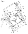
- Figure 3 is a partial view, in perspective from below and on an enlarged scale, when the stepladder is in use position.
- Figures 4, 5 and 6 are perspective views, from the front and under, when the step stool is, respectively, in the storage position, being deployed and deployed.
- FIG. 7 is a perspective view from the rear of another embodiment in which each of the support legs is provided with a level compensator
- Figures 8 and 9 are views, respectively, of side elevation with partial and partial sectional section along 9-9 of figure 8 , showing a leg on an enlarged scale.
- this stool comprises a rise plane M composed of uprights 2 and bars 3 which extend vertically to a height less than the uprights and which, in the embodiment shown, extend substantially at half height.
- a folding platform 4 is articulated around a horizontal axis and, in particular, on the last bar 3a. The articulation is achieved by sockets 5, or equivalent means, disposed under the rear edge of the platform and so that it can be deployed forward.
- the stepladder also comprises two support legs 6 articulated each at the top of one of the uprights 2, via a hinge 7, multidirectional or with several degrees of freedom. On each leg can slide a collar 8 or other equivalent member, whose travel downward is limited by a stop ring 11. This ring defines the horizontal positioning of the platform and ensures the limitation of the spacing of the legs 6.
- Each collar 8 carries a hinge 9 by which it is articulated at the end of a lateral tie rod 10, constituted by a rigid lever.
- the other end of each pulling is articulated on the upright 2 of the rise plane M by a hinge 12, multidirectional or with several degrees of freedom.
- the various figures show that this articulation is disposed above the bar 3a forming the articulation of the platform.
- the platform 4 is associated with a collapsible guard 13 whose lateral branches 14 are articulated, near their front ends and by pins 15, to the vertices of the uprights 2.
- the rear end of each branches 14 of the bodyguard are connected, by a connecting rod 16, to the rear end of the platform 4.
- the lower end of each connecting rod 16 is connected to the platform by a hinge 17, while its upper end is connected, by a hinge 18, to a collar 19 slidably mounted on the corresponding branch 14.
- each collar is limited and takes place between two locking notches, respectively posterior 20a and anterior 20b, visible to the figures 3 , 5 and 6 , and defining, the first, the normal position of the guardrail, and, the second, a transient position facilitating the access of the user to the platform 4.
- the stepladder also comprises means which ensure the automatic spacing of the legs when it is placed in the position of use.
- These means comprise two spreader arms 22 which are arranged under the platform 4. figure 3 the posterior ends of the arms 22 are articulated on a common pivot 23, orthogonal to the platform and protruding from its bottom, while their anterior ends are connected to one of the two collars 8 by a hinge 24.
- the pivot 23 is disposed substantially in the middle of the width of the platform 4 and between the half and the back third of its length.
- Each of the spreader arms 22 passes through an opening 25a formed in a fitting 25 attached under the plate 4 and near each of its front angles.
- the edges of each opening cooperate with the corresponding arm 22 to guide it transversely with respect to the platform, so that its movements take place in a plane parallel to that of the platform, regardless of the position of this platform relative to the plane. climb that carries it.
- the automatic spacing means comprise an arm 22 and a tie rod 10 which are articulated on the same collar 8, and form two sides of a deformable triangle whose third side, shown in FIG. C3 at the Figure 3 is virtual and extends between the pivot 23 and the hinge 12 of the tie rod on the upright 2.
- the legs 6 are arranged against the front face of this plane and between the uprights 2.
- the collars 8 are at the highest on the legs, in relation to the length of the tie rods 10 which extend vertically upwards and between the uprights 2 from the joints 12.
- the spreader arms 22 are entirely between the uprights 2 and define an angle a .
- the use position of the ladder is made by manually pivoting the platform 4 downwards and forwards, as shown by the arrow 41 to the figure 5 .
- the arms 22 are driven by the platform 4 and, by the collars 8 and tie rods 10, force the legs 6 to pivot about their joints 7 away from the uprights 2.
- the arms 22 move apart, as shown by the angle b at the figure 6 , Greater than that of a figure 4 .
- the collars 8 slide on the legs, they communicate to them a movement of spacing towards the front and a movement of separation towards the sides until the end of tilting platform 4.
- the movements of the spreader arms 22 are controlled by the movement of the pivot 23 which, when lowered, moves away from the joints 12 and increases the length of the virtual sides C3 of each of the leg control triangles 6 .
- the spacer means not only act automatically, without the need for human intervention in addition to that necessary for the deployment of the platform, but give the support legs a gap of EM value, visible figure 2 , much higher than the starting value Em, visible figure 4 , by improving the ground support surface and the stability of the stepladder.
- stepladder When the stepladder is in the position of use, access to its platform is facilitated by temporarily pushing the rods 16 forward, by sliding their collars 19 to 20b wedges 20b. As soon as the user is on the platform, he is encouraged to bring the connecting rods back locked position, by the inclination given to the guard rail by these rods.
- each leg includes means for adjusting its length to compensate for a difference in height of the bearing surface to maintain the platform 4 in a substantially horizontal position. More precisely, each leg 6 is formed by two telescopic elements, upper 6a and lower 6b respectively. The upper one 6a serves as a slide on the collar 8 carrying the hinges, respectively, 9 of the tie rod 10 and 24 of the corresponding spacer arm.
- This element 6a carries at its lower end the abutment ring 11, limiting the downward stroke of the collar 8. It also comprises, above this ring, a longitudinal groove 30 into which notches 31, staggered longitudinally, c ' that is, distributed along the element with a regular pitch and over the entire length of adjustment.
- the pitch is of the order of 20 to 25 millimeters for an adjustment stroke of the order of 160 to 200 millimeters measured on either side of a central position, considered optimal.
- the figure 8 shows that the notches 31 go upwardly leaving the groove 30 to be self-locking by the sole mass of the stool and, of course, by the mass of the stepladder and the user.
- the lower element 6b is tubular, like the one 6a in which it is slidably mounted. Near its upper end the lower element 6b is traversed by a rod 32 projecting radially on one side to form a finger 32a. It is slidably mounted in the groove 30 and is able to penetrate any of the locking notches 31.
- the figure 9 shows that the rod 32 of the lower element 6b is connected by elastic return means, such as a tension spring 33, to another rod 34 passing through the upper element 6a.
- elastic return means such as a tension spring 33
- the lower element 6a is constantly stressed by a tensile force T which tends to return it into the upper element 6a and, especially, to press the finger 32a into its notch 31, as shown figure 8 .
- This height compensation can also be used to position the stepladder on a stairway, to absorb the difference in level of at least one step 35 as shown in FIG. figure 7 .
Landscapes
- Engineering & Computer Science (AREA)
- Mechanical Engineering (AREA)
- Ladders (AREA)
- Medicines Containing Plant Substances (AREA)
- Luminescent Compositions (AREA)
- Credit Cards Or The Like (AREA)
- Orthopedics, Nursing, And Contraception (AREA)
Applications Claiming Priority (1)
| Application Number | Priority Date | Filing Date | Title |
|---|---|---|---|
| FR0800086A FR2926106B1 (fr) | 2008-01-08 | 2008-01-08 | Escabeau avec plateforme rabattable et jambes d'appui ecartables |
Publications (2)
| Publication Number | Publication Date |
|---|---|
| EP2078819A1 true EP2078819A1 (de) | 2009-07-15 |
| EP2078819B1 EP2078819B1 (de) | 2010-09-29 |
Family
ID=39688876
Family Applications (1)
| Application Number | Title | Priority Date | Filing Date |
|---|---|---|---|
| EP08356152A Active EP2078819B1 (de) | 2008-01-08 | 2008-12-15 | Trittleiter mit herunterklappbarer Plattform und spreizbaren Stützbeinen |
Country Status (5)
| Country | Link |
|---|---|
| EP (1) | EP2078819B1 (de) |
| AT (1) | ATE483091T1 (de) |
| DE (1) | DE602008002807D1 (de) |
| ES (1) | ES2353354T3 (de) |
| FR (1) | FR2926106B1 (de) |
Cited By (5)
| Publication number | Priority date | Publication date | Assignee | Title |
|---|---|---|---|---|
| FR2966864A1 (fr) * | 2010-11-02 | 2012-05-04 | Aud Innov | Ecarteur de jambes de stabilisation pour equipement d'ascension |
| EP2738345A1 (de) | 2012-11-30 | 2014-06-04 | Audio Innov | Trittleiter mit klappbarer Plattform und klappbaren Holmen |
| EP3015640A1 (de) | 2014-10-31 | 2016-05-04 | Audio Innov | Aufstiegsausstattung mit faltbarer plattform und geländern |
| EP3940189A1 (de) | 2020-07-15 | 2022-01-19 | CDH Group | Vorrichtung zum arbeiten in der höhe mit gelenkgeländer und automatischer tür |
| FR3113695A1 (fr) | 2020-08-27 | 2022-03-04 | Cdh Group | Dispositif de travail en hauteur a garde-corps articule et moyen de maintien en position repliee |
Families Citing this family (1)
| Publication number | Priority date | Publication date | Assignee | Title |
|---|---|---|---|---|
| CN108528752B (zh) * | 2018-06-04 | 2023-08-18 | 四川航泰航空装备有限公司 | 一种通用后舱工作梯 |
Citations (4)
| Publication number | Priority date | Publication date | Assignee | Title |
|---|---|---|---|---|
| US2650014A (en) * | 1951-01-05 | 1953-08-25 | Harrison Henry | Stepladder |
| US2997127A (en) | 1959-10-07 | 1961-08-22 | Wojtowicz Michael | Stepladder with improved stabilizing legs |
| US3057432A (en) * | 1959-08-24 | 1962-10-09 | Harrison Henry | Folding step stool |
| US4249637A (en) * | 1979-09-28 | 1981-02-10 | Glasgow David A | Tripod stepladder |
-
2008
- 2008-01-08 FR FR0800086A patent/FR2926106B1/fr not_active Expired - Fee Related
- 2008-12-15 ES ES08356152T patent/ES2353354T3/es active Active
- 2008-12-15 EP EP08356152A patent/EP2078819B1/de active Active
- 2008-12-15 DE DE602008002807T patent/DE602008002807D1/de active Active
- 2008-12-15 AT AT08356152T patent/ATE483091T1/de not_active IP Right Cessation
Patent Citations (4)
| Publication number | Priority date | Publication date | Assignee | Title |
|---|---|---|---|---|
| US2650014A (en) * | 1951-01-05 | 1953-08-25 | Harrison Henry | Stepladder |
| US3057432A (en) * | 1959-08-24 | 1962-10-09 | Harrison Henry | Folding step stool |
| US2997127A (en) | 1959-10-07 | 1961-08-22 | Wojtowicz Michael | Stepladder with improved stabilizing legs |
| US4249637A (en) * | 1979-09-28 | 1981-02-10 | Glasgow David A | Tripod stepladder |
Cited By (7)
| Publication number | Priority date | Publication date | Assignee | Title |
|---|---|---|---|---|
| FR2966864A1 (fr) * | 2010-11-02 | 2012-05-04 | Aud Innov | Ecarteur de jambes de stabilisation pour equipement d'ascension |
| EP2738345A1 (de) | 2012-11-30 | 2014-06-04 | Audio Innov | Trittleiter mit klappbarer Plattform und klappbaren Holmen |
| FR2998919A1 (fr) * | 2012-11-30 | 2014-06-06 | Aud Innov | Escabeau aplateforme rabattable et a montants pliables |
| EP3015640A1 (de) | 2014-10-31 | 2016-05-04 | Audio Innov | Aufstiegsausstattung mit faltbarer plattform und geländern |
| EP3940189A1 (de) | 2020-07-15 | 2022-01-19 | CDH Group | Vorrichtung zum arbeiten in der höhe mit gelenkgeländer und automatischer tür |
| FR3112570A1 (fr) | 2020-07-15 | 2022-01-21 | Cdh Group | Dispositif de travail en hauteur a garde-corps articule et portillon automatique |
| FR3113695A1 (fr) | 2020-08-27 | 2022-03-04 | Cdh Group | Dispositif de travail en hauteur a garde-corps articule et moyen de maintien en position repliee |
Also Published As
| Publication number | Publication date |
|---|---|
| DE602008002807D1 (de) | 2010-11-11 |
| EP2078819B1 (de) | 2010-09-29 |
| FR2926106B1 (fr) | 2009-12-25 |
| FR2926106A1 (fr) | 2009-07-10 |
| ES2353354T3 (es) | 2011-03-01 |
| ATE483091T1 (de) | 2010-10-15 |
Similar Documents
| Publication | Publication Date | Title |
|---|---|---|
| EP3015640B1 (de) | Aufstiegsausstattung mit faltbarer plattform und geländern | |
| EP2078819B1 (de) | Trittleiter mit herunterklappbarer Plattform und spreizbaren Stützbeinen | |
| EP2818625B1 (de) | Trittleiter mit versenkbaren Rädern, die vom Geländer aus gesteuert werden | |
| EP2738345B1 (de) | Trittleiter mit klappbarer Plattform und klappbaren Holmen | |
| EP3415707B1 (de) | Zusammenklappbare arbeitsplattform mit geringem platzbedarf und mit sicherheitsgeländer | |
| EP3192942B1 (de) | Gerüst, das zwei leitereinheiten umfasst, deren abstand voneinander durch eine vormontierte ausklappbare basis aufrechterhalten wird | |
| EP0468907A1 (de) | Zusammenklappbare Stutz-Konsole für Wandschalungen | |
| EP1914378A1 (de) | Sicherheits-Schiebeleiter für Arbeiten in großer Höhe | |
| FR3012510A1 (fr) | Echelle equipee d'un poste de travail articule verrouillable en configuration deployee au moyen d'un mecanisme de compas | |
| FR2701642A1 (fr) | Perfectionnements aux tribunes à gradins, à éléments télescopiques. | |
| EP3192941A1 (de) | Gerüst, das ein absenkbares geländer umfasst | |
| EP2806097B1 (de) | Trittstufe mit einziehbaren Rädern, und mit einem handbedienten Schwenkvorderrad | |
| FR3004202A1 (fr) | Escalier pliable et rabattable sur un mur | |
| EP3816391B1 (de) | Sicherheits-trittleiter mit sperre mit erhöhter sicherheit | |
| EP0814219A1 (de) | Leichte transportabele Arbeitsplattform | |
| WO2021148732A1 (fr) | Abri repliable de type gazebo | |
| EP3192940A1 (de) | Gerüst, das zwei ausfahrbare leitereinheiten umfasst und ein geländer stützt | |
| FR2780440A1 (fr) | Plate-forme marchepieds | |
| FR2626865A1 (fr) | Nacelle pour fleche telescopique d'engin de levage | |
| FR2760605A1 (fr) | Dispositif de protection de type parasol ou parapluie a mat excentre | |
| EP0065492A2 (de) | Faltbare Trittleiter | |
| FR3042208A1 (fr) | Equipement d'ascension securise pour travaux au niveau d'un plafond | |
| FR3046619A1 (fr) | Echafaudage comportant deux ensembles d'echelle en plusieurs parties coulissantes les unes par rapport aux autres. | |
| FR2523424A1 (fr) | Table a combinaisons multiples | |
| EP2570321A1 (de) | Equipment of rise for the maintenance of railways |
Legal Events
| Date | Code | Title | Description |
|---|---|---|---|
| PUAI | Public reference made under article 153(3) epc to a published international application that has entered the european phase |
Free format text: ORIGINAL CODE: 0009012 |
|
| AK | Designated contracting states |
Kind code of ref document: A1 Designated state(s): AT BE BG CH CY CZ DE DK EE ES FI FR GB GR HR HU IE IS IT LI LT LU LV MC MT NL NO PL PT RO SE SI SK TR |
|
| AX | Request for extension of the european patent |
Extension state: AL BA MK RS |
|
| 17P | Request for examination filed |
Effective date: 20091222 |
|
| AKX | Designation fees paid |
Designated state(s): AT BE BG CH CY CZ DE DK EE ES FI FR GB GR HR HU IE IS IT LI LT LU LV MC MT NL NO PL PT RO SE SI SK TR |
|
| GRAP | Despatch of communication of intention to grant a patent |
Free format text: ORIGINAL CODE: EPIDOSNIGR1 |
|
| RTI1 | Title (correction) |
Free format text: STEPLADDER WITH FOLDING PLATFORM AND SEPARABLE SUPPORT LEGS |
|
| GRAS | Grant fee paid |
Free format text: ORIGINAL CODE: EPIDOSNIGR3 |
|
| GRAA | (expected) grant |
Free format text: ORIGINAL CODE: 0009210 |
|
| AK | Designated contracting states |
Kind code of ref document: B1 Designated state(s): AT BE BG CH CY CZ DE DK EE ES FI FR GB GR HR HU IE IS IT LI LT LU LV MC MT NL NO PL PT RO SE SI SK TR |
|
| REG | Reference to a national code |
Ref country code: GB Ref legal event code: FG4D Free format text: NOT ENGLISH |
|
| REG | Reference to a national code |
Ref country code: CH Ref legal event code: EP |
|
| REG | Reference to a national code |
Ref country code: IE Ref legal event code: FG4D Free format text: LANGUAGE OF EP DOCUMENT: FRENCH |
|
| REF | Corresponds to: |
Ref document number: 602008002807 Country of ref document: DE Date of ref document: 20101111 Kind code of ref document: P |
|
| PG25 | Lapsed in a contracting state [announced via postgrant information from national office to epo] |
Ref country code: FI Free format text: LAPSE BECAUSE OF FAILURE TO SUBMIT A TRANSLATION OF THE DESCRIPTION OR TO PAY THE FEE WITHIN THE PRESCRIBED TIME-LIMIT Effective date: 20100929 Ref country code: LT Free format text: LAPSE BECAUSE OF FAILURE TO SUBMIT A TRANSLATION OF THE DESCRIPTION OR TO PAY THE FEE WITHIN THE PRESCRIBED TIME-LIMIT Effective date: 20100929 Ref country code: AT Free format text: LAPSE BECAUSE OF FAILURE TO SUBMIT A TRANSLATION OF THE DESCRIPTION OR TO PAY THE FEE WITHIN THE PRESCRIBED TIME-LIMIT Effective date: 20100929 Ref country code: NO Free format text: LAPSE BECAUSE OF FAILURE TO SUBMIT A TRANSLATION OF THE DESCRIPTION OR TO PAY THE FEE WITHIN THE PRESCRIBED TIME-LIMIT Effective date: 20101229 |
|
| REG | Reference to a national code |
Ref country code: NL Ref legal event code: VDEP Effective date: 20100929 |
|
| LTIE | Lt: invalidation of european patent or patent extension |
Effective date: 20100929 |
|
| PG25 | Lapsed in a contracting state [announced via postgrant information from national office to epo] |
Ref country code: HR Free format text: LAPSE BECAUSE OF FAILURE TO SUBMIT A TRANSLATION OF THE DESCRIPTION OR TO PAY THE FEE WITHIN THE PRESCRIBED TIME-LIMIT Effective date: 20100929 Ref country code: SI Free format text: LAPSE BECAUSE OF FAILURE TO SUBMIT A TRANSLATION OF THE DESCRIPTION OR TO PAY THE FEE WITHIN THE PRESCRIBED TIME-LIMIT Effective date: 20100929 |
|
| REG | Reference to a national code |
Ref country code: ES Ref legal event code: FG2A Effective date: 20110217 |
|
| PG25 | Lapsed in a contracting state [announced via postgrant information from national office to epo] |
Ref country code: LV Free format text: LAPSE BECAUSE OF FAILURE TO SUBMIT A TRANSLATION OF THE DESCRIPTION OR TO PAY THE FEE WITHIN THE PRESCRIBED TIME-LIMIT Effective date: 20100929 Ref country code: SE Free format text: LAPSE BECAUSE OF FAILURE TO SUBMIT A TRANSLATION OF THE DESCRIPTION OR TO PAY THE FEE WITHIN THE PRESCRIBED TIME-LIMIT Effective date: 20100929 Ref country code: GR Free format text: LAPSE BECAUSE OF FAILURE TO SUBMIT A TRANSLATION OF THE DESCRIPTION OR TO PAY THE FEE WITHIN THE PRESCRIBED TIME-LIMIT Effective date: 20101230 |
|
| REG | Reference to a national code |
Ref country code: IE Ref legal event code: FD4D |
|
| PG25 | Lapsed in a contracting state [announced via postgrant information from national office to epo] |
Ref country code: SK Free format text: LAPSE BECAUSE OF FAILURE TO SUBMIT A TRANSLATION OF THE DESCRIPTION OR TO PAY THE FEE WITHIN THE PRESCRIBED TIME-LIMIT Effective date: 20100929 Ref country code: RO Free format text: LAPSE BECAUSE OF FAILURE TO SUBMIT A TRANSLATION OF THE DESCRIPTION OR TO PAY THE FEE WITHIN THE PRESCRIBED TIME-LIMIT Effective date: 20100929 Ref country code: EE Free format text: LAPSE BECAUSE OF FAILURE TO SUBMIT A TRANSLATION OF THE DESCRIPTION OR TO PAY THE FEE WITHIN THE PRESCRIBED TIME-LIMIT Effective date: 20100929 Ref country code: NL Free format text: LAPSE BECAUSE OF FAILURE TO SUBMIT A TRANSLATION OF THE DESCRIPTION OR TO PAY THE FEE WITHIN THE PRESCRIBED TIME-LIMIT Effective date: 20100929 Ref country code: PT Free format text: LAPSE BECAUSE OF FAILURE TO SUBMIT A TRANSLATION OF THE DESCRIPTION OR TO PAY THE FEE WITHIN THE PRESCRIBED TIME-LIMIT Effective date: 20110131 Ref country code: CZ Free format text: LAPSE BECAUSE OF FAILURE TO SUBMIT A TRANSLATION OF THE DESCRIPTION OR TO PAY THE FEE WITHIN THE PRESCRIBED TIME-LIMIT Effective date: 20100929 Ref country code: IS Free format text: LAPSE BECAUSE OF FAILURE TO SUBMIT A TRANSLATION OF THE DESCRIPTION OR TO PAY THE FEE WITHIN THE PRESCRIBED TIME-LIMIT Effective date: 20110129 |
|
| BERE | Be: lapsed |
Owner name: AUDINNOV Effective date: 20101231 |
|
| PG25 | Lapsed in a contracting state [announced via postgrant information from national office to epo] |
Ref country code: IE Free format text: LAPSE BECAUSE OF FAILURE TO SUBMIT A TRANSLATION OF THE DESCRIPTION OR TO PAY THE FEE WITHIN THE PRESCRIBED TIME-LIMIT Effective date: 20100929 Ref country code: MC Free format text: LAPSE BECAUSE OF NON-PAYMENT OF DUE FEES Effective date: 20101231 |
|
| PLBE | No opposition filed within time limit |
Free format text: ORIGINAL CODE: 0009261 |
|
| STAA | Information on the status of an ep patent application or granted ep patent |
Free format text: STATUS: NO OPPOSITION FILED WITHIN TIME LIMIT |
|
| PG25 | Lapsed in a contracting state [announced via postgrant information from national office to epo] |
Ref country code: DK Free format text: LAPSE BECAUSE OF FAILURE TO SUBMIT A TRANSLATION OF THE DESCRIPTION OR TO PAY THE FEE WITHIN THE PRESCRIBED TIME-LIMIT Effective date: 20100929 Ref country code: PL Free format text: LAPSE BECAUSE OF FAILURE TO SUBMIT A TRANSLATION OF THE DESCRIPTION OR TO PAY THE FEE WITHIN THE PRESCRIBED TIME-LIMIT Effective date: 20100929 |
|
| PG25 | Lapsed in a contracting state [announced via postgrant information from national office to epo] |
Ref country code: BE Free format text: LAPSE BECAUSE OF NON-PAYMENT OF DUE FEES Effective date: 20101231 |
|
| REG | Reference to a national code |
Ref country code: DE Ref legal event code: R097 Ref document number: 602008002807 Country of ref document: DE Effective date: 20110630 |
|
| PG25 | Lapsed in a contracting state [announced via postgrant information from national office to epo] |
Ref country code: MT Free format text: LAPSE BECAUSE OF FAILURE TO SUBMIT A TRANSLATION OF THE DESCRIPTION OR TO PAY THE FEE WITHIN THE PRESCRIBED TIME-LIMIT Effective date: 20100929 |
|
| PG25 | Lapsed in a contracting state [announced via postgrant information from national office to epo] |
Ref country code: CY Free format text: LAPSE BECAUSE OF FAILURE TO SUBMIT A TRANSLATION OF THE DESCRIPTION OR TO PAY THE FEE WITHIN THE PRESCRIBED TIME-LIMIT Effective date: 20100929 |
|
| PG25 | Lapsed in a contracting state [announced via postgrant information from national office to epo] |
Ref country code: HU Free format text: LAPSE BECAUSE OF FAILURE TO SUBMIT A TRANSLATION OF THE DESCRIPTION OR TO PAY THE FEE WITHIN THE PRESCRIBED TIME-LIMIT Effective date: 20110330 Ref country code: BG Free format text: LAPSE BECAUSE OF FAILURE TO SUBMIT A TRANSLATION OF THE DESCRIPTION OR TO PAY THE FEE WITHIN THE PRESCRIBED TIME-LIMIT Effective date: 20100929 Ref country code: LU Free format text: LAPSE BECAUSE OF NON-PAYMENT OF DUE FEES Effective date: 20101215 |
|
| PG25 | Lapsed in a contracting state [announced via postgrant information from national office to epo] |
Ref country code: TR Free format text: LAPSE BECAUSE OF FAILURE TO SUBMIT A TRANSLATION OF THE DESCRIPTION OR TO PAY THE FEE WITHIN THE PRESCRIBED TIME-LIMIT Effective date: 20100929 |
|
| REG | Reference to a national code |
Ref country code: CH Ref legal event code: PL |
|
| GBPC | Gb: european patent ceased through non-payment of renewal fee |
Effective date: 20121215 |
|
| PG25 | Lapsed in a contracting state [announced via postgrant information from national office to epo] |
Ref country code: BG Free format text: LAPSE BECAUSE OF FAILURE TO SUBMIT A TRANSLATION OF THE DESCRIPTION OR TO PAY THE FEE WITHIN THE PRESCRIBED TIME-LIMIT Effective date: 20101229 |
|
| PG25 | Lapsed in a contracting state [announced via postgrant information from national office to epo] |
Ref country code: LI Free format text: LAPSE BECAUSE OF NON-PAYMENT OF DUE FEES Effective date: 20121231 Ref country code: CH Free format text: LAPSE BECAUSE OF NON-PAYMENT OF DUE FEES Effective date: 20121231 |
|
| PG25 | Lapsed in a contracting state [announced via postgrant information from national office to epo] |
Ref country code: GB Free format text: LAPSE BECAUSE OF NON-PAYMENT OF DUE FEES Effective date: 20121215 |
|
| REG | Reference to a national code |
Ref country code: FR Ref legal event code: PLFP Year of fee payment: 8 |
|
| PGFP | Annual fee paid to national office [announced via postgrant information from national office to epo] |
Ref country code: DE Payment date: 20151209 Year of fee payment: 8 Ref country code: IT Payment date: 20151215 Year of fee payment: 8 |
|
| PGFP | Annual fee paid to national office [announced via postgrant information from national office to epo] |
Ref country code: ES Payment date: 20151218 Year of fee payment: 8 |
|
| REG | Reference to a national code |
Ref country code: FR Ref legal event code: PLFP Year of fee payment: 9 |
|
| REG | Reference to a national code |
Ref country code: DE Ref legal event code: R119 Ref document number: 602008002807 Country of ref document: DE |
|
| PG25 | Lapsed in a contracting state [announced via postgrant information from national office to epo] |
Ref country code: IT Free format text: LAPSE BECAUSE OF NON-PAYMENT OF DUE FEES Effective date: 20161215 |
|
| PG25 | Lapsed in a contracting state [announced via postgrant information from national office to epo] |
Ref country code: DE Free format text: LAPSE BECAUSE OF NON-PAYMENT OF DUE FEES Effective date: 20170701 |
|
| REG | Reference to a national code |
Ref country code: FR Ref legal event code: PLFP Year of fee payment: 10 |
|
| PG25 | Lapsed in a contracting state [announced via postgrant information from national office to epo] |
Ref country code: ES Free format text: LAPSE BECAUSE OF NON-PAYMENT OF DUE FEES Effective date: 20161216 |
|
| REG | Reference to a national code |
Ref country code: ES Ref legal event code: FD2A Effective date: 20180626 |
|
| P01 | Opt-out of the competence of the unified patent court (upc) registered |
Effective date: 20230527 |
|
| PGFP | Annual fee paid to national office [announced via postgrant information from national office to epo] |
Ref country code: FR Payment date: 20231226 Year of fee payment: 16 |