EP2078596A1 - Klebstoffverteilungsvorrichtung - Google Patents
Klebstoffverteilungsvorrichtung Download PDFInfo
- Publication number
- EP2078596A1 EP2078596A1 EP09158812A EP09158812A EP2078596A1 EP 2078596 A1 EP2078596 A1 EP 2078596A1 EP 09158812 A EP09158812 A EP 09158812A EP 09158812 A EP09158812 A EP 09158812A EP 2078596 A1 EP2078596 A1 EP 2078596A1
- Authority
- EP
- European Patent Office
- Prior art keywords
- glue
- roller
- doctor blade
- doctor
- adjusting
- Prior art date
- Legal status (The legal status is an assumption and is not a legal conclusion. Google has not performed a legal analysis and makes no representation as to the accuracy of the status listed.)
- Granted
Links
- 239000003292 glue Substances 0.000 title claims abstract description 77
- 238000007789 sealing Methods 0.000 claims description 4
- 230000001105 regulatory effect Effects 0.000 claims description 2
- 238000004026 adhesive bonding Methods 0.000 description 13
- 238000009826 distribution Methods 0.000 description 4
- 230000001276 controlling effect Effects 0.000 description 3
- 238000010438 heat treatment Methods 0.000 description 3
- 239000000463 material Substances 0.000 description 3
- 239000000853 adhesive Substances 0.000 description 2
- 230000001070 adhesive effect Effects 0.000 description 2
- 230000015572 biosynthetic process Effects 0.000 description 2
- 239000012530 fluid Substances 0.000 description 2
- 239000007788 liquid Substances 0.000 description 2
- 238000000034 method Methods 0.000 description 2
- 239000002023 wood Substances 0.000 description 2
- 239000011324 bead Substances 0.000 description 1
- 230000000295 complement effect Effects 0.000 description 1
- 238000000151 deposition Methods 0.000 description 1
- 230000000694 effects Effects 0.000 description 1
- 238000005485 electric heating Methods 0.000 description 1
- 230000005484 gravity Effects 0.000 description 1
- 239000011796 hollow space material Substances 0.000 description 1
- 239000012943 hotmelt Substances 0.000 description 1
- 238000003754 machining Methods 0.000 description 1
- 230000007257 malfunction Effects 0.000 description 1
- 230000007246 mechanism Effects 0.000 description 1
- 238000011084 recovery Methods 0.000 description 1
- 238000003892 spreading Methods 0.000 description 1
Images


Classifications
-
- B—PERFORMING OPERATIONS; TRANSPORTING
- B27—WORKING OR PRESERVING WOOD OR SIMILAR MATERIAL; NAILING OR STAPLING MACHINES IN GENERAL
- B27G—ACCESSORY MACHINES OR APPARATUS FOR WORKING WOOD OR SIMILAR MATERIALS; TOOLS FOR WORKING WOOD OR SIMILAR MATERIALS; SAFETY DEVICES FOR WOOD WORKING MACHINES OR TOOLS
- B27G11/00—Applying adhesives or glue to surfaces of wood to be joined
-
- B—PERFORMING OPERATIONS; TRANSPORTING
- B05—SPRAYING OR ATOMISING IN GENERAL; APPLYING FLUENT MATERIALS TO SURFACES, IN GENERAL
- B05C—APPARATUS FOR APPLYING FLUENT MATERIALS TO SURFACES, IN GENERAL
- B05C1/00—Apparatus in which liquid or other fluent material is applied to the surface of the work by contact with a member carrying the liquid or other fluent material, e.g. a porous member loaded with a liquid to be applied as a coating
- B05C1/006—Apparatus in which liquid or other fluent material is applied to the surface of the work by contact with a member carrying the liquid or other fluent material, e.g. a porous member loaded with a liquid to be applied as a coating for applying liquid or other fluent material to the edges of essentially flat articles
-
- B—PERFORMING OPERATIONS; TRANSPORTING
- B05—SPRAYING OR ATOMISING IN GENERAL; APPLYING FLUENT MATERIALS TO SURFACES, IN GENERAL
- B05C—APPARATUS FOR APPLYING FLUENT MATERIALS TO SURFACES, IN GENERAL
- B05C1/00—Apparatus in which liquid or other fluent material is applied to the surface of the work by contact with a member carrying the liquid or other fluent material, e.g. a porous member loaded with a liquid to be applied as a coating
- B05C1/04—Apparatus in which liquid or other fluent material is applied to the surface of the work by contact with a member carrying the liquid or other fluent material, e.g. a porous member loaded with a liquid to be applied as a coating for applying liquid or other fluent material to work of indefinite length
- B05C1/08—Apparatus in which liquid or other fluent material is applied to the surface of the work by contact with a member carrying the liquid or other fluent material, e.g. a porous member loaded with a liquid to be applied as a coating for applying liquid or other fluent material to work of indefinite length using a roller or other rotating member which contacts the work along a generating line
- B05C1/0813—Apparatus in which liquid or other fluent material is applied to the surface of the work by contact with a member carrying the liquid or other fluent material, e.g. a porous member loaded with a liquid to be applied as a coating for applying liquid or other fluent material to work of indefinite length using a roller or other rotating member which contacts the work along a generating line characterised by means for supplying liquid or other fluent material to the roller
-
- B—PERFORMING OPERATIONS; TRANSPORTING
- B05—SPRAYING OR ATOMISING IN GENERAL; APPLYING FLUENT MATERIALS TO SURFACES, IN GENERAL
- B05C—APPARATUS FOR APPLYING FLUENT MATERIALS TO SURFACES, IN GENERAL
- B05C1/00—Apparatus in which liquid or other fluent material is applied to the surface of the work by contact with a member carrying the liquid or other fluent material, e.g. a porous member loaded with a liquid to be applied as a coating
- B05C1/003—Apparatus in which liquid or other fluent material is applied to the surface of the work by contact with a member carrying the liquid or other fluent material, e.g. a porous member loaded with a liquid to be applied as a coating incorporating means for heating or cooling the liquid or other fluent material
-
- B—PERFORMING OPERATIONS; TRANSPORTING
- B05—SPRAYING OR ATOMISING IN GENERAL; APPLYING FLUENT MATERIALS TO SURFACES, IN GENERAL
- B05C—APPARATUS FOR APPLYING FLUENT MATERIALS TO SURFACES, IN GENERAL
- B05C1/00—Apparatus in which liquid or other fluent material is applied to the surface of the work by contact with a member carrying the liquid or other fluent material, e.g. a porous member loaded with a liquid to be applied as a coating
- B05C1/04—Apparatus in which liquid or other fluent material is applied to the surface of the work by contact with a member carrying the liquid or other fluent material, e.g. a porous member loaded with a liquid to be applied as a coating for applying liquid or other fluent material to work of indefinite length
- B05C1/08—Apparatus in which liquid or other fluent material is applied to the surface of the work by contact with a member carrying the liquid or other fluent material, e.g. a porous member loaded with a liquid to be applied as a coating for applying liquid or other fluent material to work of indefinite length using a roller or other rotating member which contacts the work along a generating line
- B05C1/0817—Apparatus in which liquid or other fluent material is applied to the surface of the work by contact with a member carrying the liquid or other fluent material, e.g. a porous member loaded with a liquid to be applied as a coating for applying liquid or other fluent material to work of indefinite length using a roller or other rotating member which contacts the work along a generating line characterised by means for removing partially liquid or other fluent material from the roller, e.g. scrapers
Definitions
- the present invention relates to a glue distributing apparatus, in particular an apparatus for distributing glue in a woodworking machine, such as for example an edgebanding machine or a squaring edgebanding machine.
- Such machines which typically perform edgebanding operations on panels, tables, flat elements of wood or similar material, comprise glue distributing apparatuses or gluing units that deposit or spread a layer of adhesive glue on belts, strips, beads to be applied to edges of panels, or directly to the edges of said panels.
- the adhesive used is generally a hot-melt glue that has to be appropriately heated before being applied "hot” to surfaces to be joined.
- the glue is applied by means of a suitable rotating gluing roller, that has a knurled or rough external surface, which retains and conveys the glue, supplied by a tank or pot.
- the latter is made of a non-adhering material and is provided with heating elements, such as electric resistances, for uniformly heating and keeping fluid the glue.
- the glue tank is positioned below a work area and suitable supplying means, for example screw conveyor, transfers the glue from said lower tank to the gluing roller.
- glue distributing apparatuses are known that are provided with glue tanks positioned next to the gluing roller and which extend upwards. In this way the heat generated by the tank resistances can be dissipated to the external environment and does not affect, unless marginally, the work area and in particular the roller and the corresponding movement members.
- the tank has a lower portion or chamber provided with an opening through which the glue flows by force of gravity to the gluing roller. The latter partially shuts said opening and, by rotating, transfers and spread the glue on the surfaces of the elements to be joined.
- glue adjusting means comprising fixed doctor blades for adjusting the quantity of glue to be spread onto the knurled surface of the gluing roller.
- these apparatuses can comprise a first doctor blade, called dosing doctor blade, for depositing or spreading an uniform layer of glue of a fixed thickness on the gluing roller, and a second doctor blade, called return or recovery doctor blade, which recovers the exceeding glue on the roller that has not been transferred to the surface to be glued.
- the return doctor blade moreover keeps any foreign bodies outside the chamber.
- doctor blades are arranged parallel to one another at a preset distance, opposite the opening of the lower chamber of the tank in such a way as to form a cavity in which the glue gathers that is taken from the roller.
- Each doctor blade comprises an elongated flat element, provided with an edge abutting on the gluing roller along a generatrix thereof, operating substantially as a "spatula” to spread a uniform layer of glue on said roller.
- each doctor blade may consist of a cylindrical pivot, arranged parallel to the gluing roller and provided with a longitudinal plane that constitutes a flat surface that conveys and spreads the glue on the roller.
- the presence of two distinct doctor blades requires laborious and complex management of the apparatus since adjusting operations for correctly positioning and orienting doctor blades with respect to the roller must be repeated separately for each doctor blade and need skilled operators and also long stops of the machine.
- the gluing roller can, in fact, rotate both in a clockwise and in an anticlockwise direction, according to whether, for example, strips or belts have to be glued, in the case of so-called "softforming", or panels to be edgebanded have to be glued, in the case of so-called "straight" forming.
- An object of the invention is to improve known glue distributing apparatuses, in particular for woodworking machines for machining elements of wood or similar materials. Another object is to obtain a glue distributing apparatus, which allows adjusting and controlling in a simple, fast and effective manner the glue to be spread on surfaces to be glued, regardless of a rotation direction of gluing roller.
- a glue distributing apparatus comprising roller means for applying a glue to an element to be glued, tank means containing said glue and provided with an opening for conveying said glue to said roller means, and adjusting means interposed between said roller means and said opening for adjusting a quantity of glue transferred to/from said roller means, characterised in that said adjusting means comprises movable and interconnected doctor blade means.
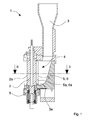
- a glue distributing apparatus comprising roller means 2, tank means 3 and adjusting means 4.
- Roller means 2 comprises a rotating roller, of known type, having a rough or knurled external surface 2a for removing, conveying and applying a preset layer of glue to an element 50 to be glued.
- the roller 2 is rotated by suitable actuating means, of known type and not shown in the Figures, and it can be rotate both clockwise and anticlockwise, depending on elements 50 to be glued.
- the roller 2 rotates clockwise to glue strips or belts in the so-called “softforming” process, whilst it rotates anticlockwise to glue edges of panels or tables to be edgebanded, in the so-called “straight” process.
- Tank means 3 which contains the glue and is placed next to the roller means 2, extends upwards and is provided with an opening 3a for conveying said glue to the roller means 2.
- the tank means 3 is further provided with a plurality of electric heating elements 23 that are able to heat and melt uniformly the glue and to maintain fluid the latter.
- the opening 3a of tank means 3 has a height that is almost the same as that of a portion of the roller 2 configured for receiving the glue.
- Adjusting means 4 is interposed between the roller means 2 and the opening 3a for regulating a quantity of glue transferred to the roller 2 for a subsequent application on an element 50 to be glued. Adjusting means 4 is further configured so as to recover from the roller 2 the exceeding glue, which has not been spread on element 50.
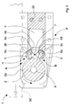
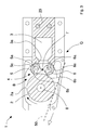
- Adjusting means 4 comprises doctor blade means 5, 6 provided with respective cavity means 5a, 6a.
- Doctor blade means comprise a first doctor blade 5 and a second doctor blade 6.
- Each doctor blade 5, 6 is an element with a longitudinally elongated shape, for example a pin with an approximately cylindrical section, on which a respective cavity 5a, 6a is made, consisting of an open hollow space that extends longitudinally for about the entire length of the element.
- the cavity 5a, 6a is for example a straight groove with a U-shaped cross section having a concave bottom wall.
- the two doctor blade 5, 6 are arranged parallel each other and spaced apart from one another in such a way that the respective cavities 5a, 6a are almost face one another to form a volume or space 7 that is shaped for containing the glue. It has been find out that such cavities 5a, 6a reduce and limit considerably the formation of turbulences and vortices in the liquid glue during rotation of roller 2. This enables an almost uniform and homogenous distribution of the glue on the whole length of roller 2 to be obtained, regardless of a rotation speed of roller 2.
- Each doctor blade 5, 6 comprises an abutting portion 5b, 6b, configured so as to contact the roller 2, and a sealing portion 5c, 6c suitable for abutting on a respective seat 3b, 3c of tank means 3.
- the abutting portion 5b, 6b is, for example, an edge made on an external surface of the doctor blade, whilst the sealing portion 5c, 6c is a portion of said external surface, having a concave shape, complementary to a shape of seat 3b, 3c, for example a portion of cylindrical surface.
- Each doctor blade 5, 6 is rotatably mounted around a respective rotation axis 5d, 6d, so as to be movable between a first working position A and a respective second working position B.
- the rotation axes 5d, 6d are parallel to one another and also parallel to a rotation shaft 8 of the roller 2.
- the abutting portion 5b, 6b of the doctor blade 5, 6 substantially abuts on the external surface 2a of the roller 2 in such a way as to adjust the passage of glue to be deposited onto the roller and to uniformly extend said glue onto said outside surface 2a.
- the abutting portion 5b, 6b of doctor blade 5, 6 is spaced from a respective external surface 2a of roller 2 to enable the exceeding glue on the roller 2 to be recovered and at the same time to prevent possible foreign bodies entering the volume 7.
- Driving means of known type and not shown in the Figures, is provided for rotating the doctor blades 5, 6 between the two working positions.
- the doctor blades 5, 6 can be mounted so as to independently rotate, driven separately by respective driving means.
- doctor blades 5, 6 can be mounted linked together and connected by suitable interconnecting means, in such a way as to rotate together.
- Said interconnecting means can be of mechanical type, for example pulley or gear mechanisms, or of electronic type, for example electronic control means of actuating means.
- a rotation of a doctor blade is matched by a same rotation of the other doctor blade. More specifically and with reference to Figures 2 and 3 , when for example the first doctor blade 5 is in the respective first working position A, the second doctor blade 6 is in the respective second working position B.
- the apparatus 1 is in a first operating configuration P in which the roller 2 rotates in an anticlockwise direction, for example to apply glue to an edge of a panel 50.
- the apparatus 1 is in a second operating configuration Q wherein the roller 2 rotates in a clockwise direction, for example to apply glue to a strip or belt 50.
- the doctor blade 5, 6 can also be made as a single body. In this case, the respective rotation axes 5d, 6d are coincident.
- FIGS 4 to 7 show a version of the apparatus 1 which comprises shutting means 10, that is movable and interposed between the roller 2 and the opening 3a of the tank means 3 for closing and/or opening said opening 3a.
- shutting means 10 can be inserted between the adjusting means 4 and said opening 3a.
- Shutting means 10 is movable between a closed position C, in which it shuts said opening 3a to prevent the glue passing from the tank means 3 to the roller 2 ( Figure 7 ), and a complete open position D, in which it opens said opening 3a and enables the glue to pass through ( Figures 5, 6 ).
- the shutting means 10 can adjust a glue flow to the roller 2, partially closing the opening 3a.
- Shutting means 10 comprises an elongated element, substantially cylindrical, rotatably mounted on a rotating pin 11.
- Shutting means 10 further has a passage 12 comprising a longitudinal through opening that enables the glue to transit and which has a length that is almost equal to a height of the opening 3a.
- Shutting means 10 is contained in a suitable respective seat 3d made in the tank means 3, inside which it can rotate.
- the adjusting means 4 comprises a couple of doctor blades 15, 16 made of a single body and rotatable around respective rotation axes 15d, 16d that in this case coincide.
- the adjusting means 4 comprises an elongated tubular element 19 that is substantially cylindrical with open section, provided with two facing and opposite portions 15, 16 acting as doctor blades.
- Each doctor blade 15, 16 has a respective abutting portion 15b, 16b, configured so as to abut on the external surface 2a of the roller 2, and a respective sealing portion 15c, 16c configured so as to abut on said respective seat 3d of tank means 3.
- the tubular body 19 of the adjusting means 4 has an internal cylindrical cavity 17 into which the shutting means 10 is inserted coaxially.
- Glue coming from the tank means 3 can pass through the slot 18 to reach roller means 2.
- This version of the distributing apparatus 1 thus comprises adjusting means 4 and shutting means 10 in a very compact structure.
- Adjusting means 4 that comprises two doctor blades 15, 16, that are integral and movable at the same time, allows adjusting and controlling in a simple, rapid and effective manner a distribution of the glue on surfaces to be glue, regardless of a rotation direction of the roller 2.
- shutting means 10 can close hermetically the opening 3a, thus preventing glue from reaching the roller 2 and leaking through passages and openings of the external surface 2a of said roller during stop phases of the apparatus.
- Shutting means 10 comprises a couple of recesses 13, 14, made on an internal wall of the passage 12 for an entire extent of the latter.
- Recesses 13, 14 are substantially the same and symmetrically arranged with respect to a longitudinal plane of symmetry S of shutting means 4.
- said recesses 13, 14, which have an almost U-shaped section, are arranged so as to form a respective cavity 20 converging on roller means 2.
- respective cavities can be provided on the walls of the tubular body 19 of adjusting means 4 at the doctor blades 15, 16.
Landscapes
- Life Sciences & Earth Sciences (AREA)
- Engineering & Computer Science (AREA)
- Mechanical Engineering (AREA)
- Wood Science & Technology (AREA)
- Forests & Forestry (AREA)
- Coating Apparatus (AREA)
- Materials For Medical Uses (AREA)
- Seal Device For Vehicle (AREA)
- Multi-Process Working Machines And Systems (AREA)
- Non-Silver Salt Photosensitive Materials And Non-Silver Salt Photography (AREA)
- Blow-Moulding Or Thermoforming Of Plastics Or The Like (AREA)
Applications Claiming Priority (2)
| Application Number | Priority Date | Filing Date | Title |
|---|---|---|---|
| IT000319A ITMO20050319A1 (it) | 2005-11-29 | 2005-11-29 | Apparato distributore di colla |
| EP06024600A EP1798013B1 (de) | 2005-11-29 | 2006-11-28 | Leimauftragsvorrichtung |
Related Parent Applications (2)
| Application Number | Title | Priority Date | Filing Date |
|---|---|---|---|
| EP06024600.6 Division | 2006-11-28 | ||
| EP06024600A Division EP1798013B1 (de) | 2005-11-29 | 2006-11-28 | Leimauftragsvorrichtung |
Publications (2)
| Publication Number | Publication Date |
|---|---|
| EP2078596A1 true EP2078596A1 (de) | 2009-07-15 |
| EP2078596B1 EP2078596B1 (de) | 2011-04-27 |
Family
ID=37964968
Family Applications (3)
| Application Number | Title | Priority Date | Filing Date |
|---|---|---|---|
| EP06024600A Active EP1798013B1 (de) | 2005-11-29 | 2006-11-28 | Leimauftragsvorrichtung |
| EP09158805A Active EP2078595B1 (de) | 2005-11-29 | 2006-11-28 | Klebstoffverteilungsvorrichtung |
| EP09158812A Active EP2078596B1 (de) | 2005-11-29 | 2006-11-28 | Klebstoffverteilungsvorrichtung |
Family Applications Before (2)
| Application Number | Title | Priority Date | Filing Date |
|---|---|---|---|
| EP06024600A Active EP1798013B1 (de) | 2005-11-29 | 2006-11-28 | Leimauftragsvorrichtung |
| EP09158805A Active EP2078595B1 (de) | 2005-11-29 | 2006-11-28 | Klebstoffverteilungsvorrichtung |
Country Status (5)
| Country | Link |
|---|---|
| EP (3) | EP1798013B1 (de) |
| AT (3) | ATE510666T1 (de) |
| DE (2) | DE602006007663D1 (de) |
| ES (3) | ES2367094T3 (de) |
| IT (1) | ITMO20050319A1 (de) |
Families Citing this family (18)
| Publication number | Priority date | Publication date | Assignee | Title |
|---|---|---|---|---|
| DE202009006794U1 (de) * | 2009-05-12 | 2009-09-03 | Homag Holzbearbeitungssysteme Ag | Anleimaggregat |
| IT1396969B1 (it) | 2009-12-18 | 2012-12-20 | Scm Group Spa | Metodo di incollaggio |
| IT1402170B1 (it) * | 2010-07-21 | 2013-08-28 | Raised Floor Technologies Ltd | Stazione di bordatura per una linea di produzione di pannelli per pavimenti sopraelevati |
| IT1402067B1 (it) * | 2010-10-18 | 2013-08-28 | Scm Group Spa | Apparato e metodo di incollaggio |
| ES2395069B1 (es) * | 2011-05-30 | 2013-10-18 | Construcciones Españolas De Herramientas Industriales S.A. | Dispositivo de encolado perfeccionado. |
| DE102013019581A1 (de) * | 2013-11-21 | 2015-05-21 | Festool Gmbh | Klebemaschine mit einer Zubereitungsanordnung für ein Klebstoffvolumen |
| EP3213824B1 (de) | 2016-03-03 | 2018-06-27 | Robatech AG | Vorrichtung und verfahren zum auftragen von klebstoff auf ein substrat |
| JP6523996B2 (ja) | 2016-03-10 | 2019-06-05 | 三菱重工業株式会社 | 塗布装置 |
| CN106622838A (zh) * | 2016-12-12 | 2017-05-10 | 深圳市华星光电技术有限公司 | 一种树脂胶转印机构及涂布机 |
| CN108246559B (zh) * | 2018-04-03 | 2023-12-15 | 广东豪德数控装备股份有限公司 | 一种密封的涂胶装置 |
| CN108452999A (zh) * | 2018-04-12 | 2018-08-28 | 曾漳安 | 一种皮具生产用便携式涂胶机 |
| DE102019110567A1 (de) * | 2019-04-24 | 2020-10-29 | Homag Gmbh | Haftmittelauftragseinrichtung |
| CN110924635B (zh) * | 2019-12-12 | 2021-03-05 | 兴化市正福塑业有限公司 | 一种自动转动涂胶使操作效果更佳的地板上胶设备 |
| IT202000004510A1 (it) * | 2020-03-04 | 2021-09-04 | Luigino Salvador | Rullo spalmatore per adesivo termofondente |
| CN112710720B (zh) * | 2020-12-17 | 2023-03-24 | 深圳市职业病防治院 | 单细胞凝胶电泳铺胶方法及装置 |
| CN115591719B (zh) * | 2021-06-28 | 2026-02-27 | 南兴装备股份有限公司 | 封边涂胶装置 |
| DE102022110163A1 (de) * | 2022-04-27 | 2023-11-02 | Homag Gmbh | Vorrichtung zum Beschichten eines Werkstücks |
| IT202400002569A1 (it) * | 2024-02-07 | 2025-08-07 | Tiesse S R L S Unipersonale | Dispositivo di spalmatura |
Citations (5)
| Publication number | Priority date | Publication date | Assignee | Title |
|---|---|---|---|---|
| DE1886392U (de) * | 1963-08-06 | 1964-01-23 | Henkel & Cie Gmbh | Vorrichtung zum auftragen von klebstoff. |
| DE1577765A1 (de) * | 1963-07-04 | 1969-06-26 | Porth Erwin | Vorrichtung zum Auftragen von viskosen Fluessigkeiten auf Bogen oder Bahnen von Papier und sonstigen Werkstoffen |
| DE3447592A1 (de) * | 1984-12-28 | 1986-07-10 | Hornberger Maschinenbaugesellschaft mbH & Co KG, 7294 Schopfloch | Vorrichtung zum auftragen von schmelzkleber auf fortlaufend bewegte werkstuecke |
| EP0945235A2 (de) * | 1998-03-24 | 1999-09-29 | SCM GROUP S.p.A. | Kantenleimgerät |
| DE20104698U1 (de) * | 2001-03-19 | 2001-05-17 | Paul Ott Gmbh, Lambach | Leimbecken für eine Kantenleimmaschine |
-
2005
- 2005-11-29 IT IT000319A patent/ITMO20050319A1/it unknown
-
2006
- 2006-11-28 ES ES09158805T patent/ES2367094T3/es active Active
- 2006-11-28 AT AT09158805T patent/ATE510666T1/de active
- 2006-11-28 DE DE602006007663T patent/DE602006007663D1/de active Active
- 2006-11-28 ES ES06024600T patent/ES2329498T3/es active Active
- 2006-11-28 EP EP06024600A patent/EP1798013B1/de active Active
- 2006-11-28 EP EP09158805A patent/EP2078595B1/de active Active
- 2006-11-28 EP EP09158812A patent/EP2078596B1/de active Active
- 2006-11-28 ES ES09158812T patent/ES2365670T3/es active Active
- 2006-11-28 AT AT09158812T patent/ATE507046T1/de active
- 2006-11-28 DE DE602006021641T patent/DE602006021641D1/de active Active
- 2006-11-28 AT AT06024600T patent/ATE435727T1/de active
Patent Citations (5)
| Publication number | Priority date | Publication date | Assignee | Title |
|---|---|---|---|---|
| DE1577765A1 (de) * | 1963-07-04 | 1969-06-26 | Porth Erwin | Vorrichtung zum Auftragen von viskosen Fluessigkeiten auf Bogen oder Bahnen von Papier und sonstigen Werkstoffen |
| DE1886392U (de) * | 1963-08-06 | 1964-01-23 | Henkel & Cie Gmbh | Vorrichtung zum auftragen von klebstoff. |
| DE3447592A1 (de) * | 1984-12-28 | 1986-07-10 | Hornberger Maschinenbaugesellschaft mbH & Co KG, 7294 Schopfloch | Vorrichtung zum auftragen von schmelzkleber auf fortlaufend bewegte werkstuecke |
| EP0945235A2 (de) * | 1998-03-24 | 1999-09-29 | SCM GROUP S.p.A. | Kantenleimgerät |
| DE20104698U1 (de) * | 2001-03-19 | 2001-05-17 | Paul Ott Gmbh, Lambach | Leimbecken für eine Kantenleimmaschine |
Also Published As
| Publication number | Publication date |
|---|---|
| ATE507046T1 (de) | 2011-05-15 |
| EP1798013B1 (de) | 2009-07-08 |
| ES2367094T3 (es) | 2011-10-28 |
| DE602006007663D1 (de) | 2009-08-20 |
| EP2078596B1 (de) | 2011-04-27 |
| ITMO20050319A1 (it) | 2007-05-30 |
| ES2329498T3 (es) | 2009-11-26 |
| ATE435727T1 (de) | 2009-07-15 |
| EP1798013A1 (de) | 2007-06-20 |
| ATE510666T1 (de) | 2011-06-15 |
| EP2078595B1 (de) | 2011-05-25 |
| ES2365670T3 (es) | 2011-10-10 |
| DE602006021641D1 (de) | 2011-06-09 |
| EP2078595A1 (de) | 2009-07-15 |
Similar Documents
| Publication | Publication Date | Title |
|---|---|---|
| EP2078596B1 (de) | Klebstoffverteilungsvorrichtung | |
| EP2454010B1 (de) | Dosiersystem mit variablen volumen | |
| AU590182B2 (en) | Adhesive applicator assembly | |
| CA2569482C (en) | Apparatus for applying glue onto an advancing plane object | |
| EP2473288B1 (de) | Dosiersystem zum gleichzeitigen ausgeben zwei verschiedener haftmittel aus einem einzigen dosierer oder auftraggerät auf ein substrat | |
| US7752995B2 (en) | Slot-coating apparatus | |
| EP1894689B1 (de) | Klebstoffabgabevorrichtung | |
| CN102581895A (zh) | 配给镶边运动机构 | |
| CN105172416B (zh) | 一种胶装机的滚轮式胶锅及上胶方法 | |
| ITMO20100290A1 (it) | Apparato e metodo di incollaggio | |
| DE19719000A1 (de) | Verfahren und Vorrichtung zum Aufbringen von Leim auf Zuschnitte für Packungen | |
| JP6587316B2 (ja) | 製本装置 | |
| FI59542B (fi) | Anordning foer faestande av ett haort material pao ett saogblad | |
| US1986039A (en) | Adhesive-applying mechanism | |
| BR112021014388A2 (pt) | Dispositivo para fornecimento de adesivo | |
| EP2629983B1 (de) | Klebstoffabgabekopf in einer bindemaschine und bindemaschine mit dem abgabekopf | |
| TW201912257A (zh) | 多軸精密轉印塗膠裝置 | |
| DE4330675C2 (de) | Trocknungsanlage | |
| US8071151B2 (en) | Dual deposit stencil assembly | |
| EP1876031B1 (de) | Klebstoffauftragvorrichtung für Buchbindemaschinen | |
| IT202400002569A1 (it) | Dispositivo di spalmatura | |
| CN221046462U (zh) | 一种涂胶模块及封边机胶锅装置 | |
| DE2119477C3 (de) | Leimauftragsvorrichtung | |
| CN210906733U (zh) | 一种单张木皮专用涂胶头 | |
| TWM555754U (zh) | 雙動力水性上膠機 |
Legal Events
| Date | Code | Title | Description |
|---|---|---|---|
| PUAI | Public reference made under article 153(3) epc to a published international application that has entered the european phase |
Free format text: ORIGINAL CODE: 0009012 |
|
| AC | Divisional application: reference to earlier application |
Ref document number: 1798013 Country of ref document: EP Kind code of ref document: P |
|
| AK | Designated contracting states |
Kind code of ref document: A1 Designated state(s): AT BE BG CH CY CZ DE DK EE ES FI FR GB GR HU IE IS IT LI LT LU LV MC NL PL PT RO SE SI SK TR |
|
| 17P | Request for examination filed |
Effective date: 20100112 |
|
| 17Q | First examination report despatched |
Effective date: 20100208 |
|
| GRAP | Despatch of communication of intention to grant a patent |
Free format text: ORIGINAL CODE: EPIDOSNIGR1 |
|
| RIC1 | Information provided on ipc code assigned before grant |
Ipc: B05C 1/00 20060101ALI20101011BHEP Ipc: B27G 11/00 20060101AFI20101011BHEP Ipc: B05C 1/08 20060101ALI20101011BHEP |
|
| GRAS | Grant fee paid |
Free format text: ORIGINAL CODE: EPIDOSNIGR3 |
|
| GRAA | (expected) grant |
Free format text: ORIGINAL CODE: 0009210 |
|
| AC | Divisional application: reference to earlier application |
Ref document number: 1798013 Country of ref document: EP Kind code of ref document: P |
|
| AK | Designated contracting states |
Kind code of ref document: B1 Designated state(s): AT BE BG CH CY CZ DE DK EE ES FI FR GB GR HU IE IS IT LI LT LU LV MC NL PL PT RO SE SI SK TR |
|
| REG | Reference to a national code |
Ref country code: GB Ref legal event code: FG4D |
|
| REG | Reference to a national code |
Ref country code: CH Ref legal event code: EP |
|
| REG | Reference to a national code |
Ref country code: IE Ref legal event code: FG4D |
|
| REF | Corresponds to: |
Ref document number: 602006021641 Country of ref document: DE Date of ref document: 20110609 Kind code of ref document: P |
|
| REG | Reference to a national code |
Ref country code: DE Ref legal event code: R096 Ref document number: 602006021641 Country of ref document: DE Effective date: 20110609 |
|
| REG | Reference to a national code |
Ref country code: NL Ref legal event code: VDEP Effective date: 20110427 |
|
| LTIE | Lt: invalidation of european patent or patent extension |
Effective date: 20110427 |
|
| REG | Reference to a national code |
Ref country code: ES Ref legal event code: FG2A Ref document number: 2365670 Country of ref document: ES Kind code of ref document: T3 Effective date: 20111010 |
|
| PG25 | Lapsed in a contracting state [announced via postgrant information from national office to epo] |
Ref country code: LT Free format text: LAPSE BECAUSE OF FAILURE TO SUBMIT A TRANSLATION OF THE DESCRIPTION OR TO PAY THE FEE WITHIN THE PRESCRIBED TIME-LIMIT Effective date: 20110427 Ref country code: PT Free format text: LAPSE BECAUSE OF FAILURE TO SUBMIT A TRANSLATION OF THE DESCRIPTION OR TO PAY THE FEE WITHIN THE PRESCRIBED TIME-LIMIT Effective date: 20110829 Ref country code: SE Free format text: LAPSE BECAUSE OF FAILURE TO SUBMIT A TRANSLATION OF THE DESCRIPTION OR TO PAY THE FEE WITHIN THE PRESCRIBED TIME-LIMIT Effective date: 20110427 |
|
| PG25 | Lapsed in a contracting state [announced via postgrant information from national office to epo] |
Ref country code: SI Free format text: LAPSE BECAUSE OF FAILURE TO SUBMIT A TRANSLATION OF THE DESCRIPTION OR TO PAY THE FEE WITHIN THE PRESCRIBED TIME-LIMIT Effective date: 20110427 Ref country code: GR Free format text: LAPSE BECAUSE OF FAILURE TO SUBMIT A TRANSLATION OF THE DESCRIPTION OR TO PAY THE FEE WITHIN THE PRESCRIBED TIME-LIMIT Effective date: 20110728 Ref country code: FI Free format text: LAPSE BECAUSE OF FAILURE TO SUBMIT A TRANSLATION OF THE DESCRIPTION OR TO PAY THE FEE WITHIN THE PRESCRIBED TIME-LIMIT Effective date: 20110427 Ref country code: CY Free format text: LAPSE BECAUSE OF FAILURE TO SUBMIT A TRANSLATION OF THE DESCRIPTION OR TO PAY THE FEE WITHIN THE PRESCRIBED TIME-LIMIT Effective date: 20110427 Ref country code: BE Free format text: LAPSE BECAUSE OF FAILURE TO SUBMIT A TRANSLATION OF THE DESCRIPTION OR TO PAY THE FEE WITHIN THE PRESCRIBED TIME-LIMIT Effective date: 20110427 Ref country code: IS Free format text: LAPSE BECAUSE OF FAILURE TO SUBMIT A TRANSLATION OF THE DESCRIPTION OR TO PAY THE FEE WITHIN THE PRESCRIBED TIME-LIMIT Effective date: 20110827 Ref country code: LV Free format text: LAPSE BECAUSE OF FAILURE TO SUBMIT A TRANSLATION OF THE DESCRIPTION OR TO PAY THE FEE WITHIN THE PRESCRIBED TIME-LIMIT Effective date: 20110427 |
|
| PG25 | Lapsed in a contracting state [announced via postgrant information from national office to epo] |
Ref country code: NL Free format text: LAPSE BECAUSE OF FAILURE TO SUBMIT A TRANSLATION OF THE DESCRIPTION OR TO PAY THE FEE WITHIN THE PRESCRIBED TIME-LIMIT Effective date: 20110427 |
|
| PG25 | Lapsed in a contracting state [announced via postgrant information from national office to epo] |
Ref country code: EE Free format text: LAPSE BECAUSE OF FAILURE TO SUBMIT A TRANSLATION OF THE DESCRIPTION OR TO PAY THE FEE WITHIN THE PRESCRIBED TIME-LIMIT Effective date: 20110427 Ref country code: CZ Free format text: LAPSE BECAUSE OF FAILURE TO SUBMIT A TRANSLATION OF THE DESCRIPTION OR TO PAY THE FEE WITHIN THE PRESCRIBED TIME-LIMIT Effective date: 20110427 |
|
| PG25 | Lapsed in a contracting state [announced via postgrant information from national office to epo] |
Ref country code: PL Free format text: LAPSE BECAUSE OF FAILURE TO SUBMIT A TRANSLATION OF THE DESCRIPTION OR TO PAY THE FEE WITHIN THE PRESCRIBED TIME-LIMIT Effective date: 20110427 Ref country code: SK Free format text: LAPSE BECAUSE OF FAILURE TO SUBMIT A TRANSLATION OF THE DESCRIPTION OR TO PAY THE FEE WITHIN THE PRESCRIBED TIME-LIMIT Effective date: 20110427 |
|
| PLBE | No opposition filed within time limit |
Free format text: ORIGINAL CODE: 0009261 |
|
| STAA | Information on the status of an ep patent application or granted ep patent |
Free format text: STATUS: NO OPPOSITION FILED WITHIN TIME LIMIT |
|
| 26N | No opposition filed |
Effective date: 20120130 |
|
| REG | Reference to a national code |
Ref country code: DE Ref legal event code: R097 Ref document number: 602006021641 Country of ref document: DE Effective date: 20120130 |
|
| PG25 | Lapsed in a contracting state [announced via postgrant information from national office to epo] |
Ref country code: IT Free format text: LAPSE BECAUSE OF FAILURE TO SUBMIT A TRANSLATION OF THE DESCRIPTION OR TO PAY THE FEE WITHIN THE PRESCRIBED TIME-LIMIT Effective date: 20110427 |
|
| PG25 | Lapsed in a contracting state [announced via postgrant information from national office to epo] |
Ref country code: MC Free format text: LAPSE BECAUSE OF NON-PAYMENT OF DUE FEES Effective date: 20111130 |
|
| REG | Reference to a national code |
Ref country code: CH Ref legal event code: PL |
|
| GBPC | Gb: european patent ceased through non-payment of renewal fee |
Effective date: 20111128 |
|
| PG25 | Lapsed in a contracting state [announced via postgrant information from national office to epo] |
Ref country code: LI Free format text: LAPSE BECAUSE OF NON-PAYMENT OF DUE FEES Effective date: 20111130 Ref country code: CH Free format text: LAPSE BECAUSE OF NON-PAYMENT OF DUE FEES Effective date: 20111130 |
|
| REG | Reference to a national code |
Ref country code: FR Ref legal event code: ST Effective date: 20120731 |
|
| REG | Reference to a national code |
Ref country code: IE Ref legal event code: MM4A |
|
| PG25 | Lapsed in a contracting state [announced via postgrant information from national office to epo] |
Ref country code: IE Free format text: LAPSE BECAUSE OF NON-PAYMENT OF DUE FEES Effective date: 20111128 Ref country code: GB Free format text: LAPSE BECAUSE OF NON-PAYMENT OF DUE FEES Effective date: 20111128 |
|
| PG25 | Lapsed in a contracting state [announced via postgrant information from national office to epo] |
Ref country code: FR Free format text: LAPSE BECAUSE OF NON-PAYMENT OF DUE FEES Effective date: 20111130 |
|
| PG25 | Lapsed in a contracting state [announced via postgrant information from national office to epo] |
Ref country code: LU Free format text: LAPSE BECAUSE OF NON-PAYMENT OF DUE FEES Effective date: 20111128 |
|
| PG25 | Lapsed in a contracting state [announced via postgrant information from national office to epo] |
Ref country code: BG Free format text: LAPSE BECAUSE OF FAILURE TO SUBMIT A TRANSLATION OF THE DESCRIPTION OR TO PAY THE FEE WITHIN THE PRESCRIBED TIME-LIMIT Effective date: 20110727 |
|
| PG25 | Lapsed in a contracting state [announced via postgrant information from national office to epo] |
Ref country code: TR Free format text: LAPSE BECAUSE OF FAILURE TO SUBMIT A TRANSLATION OF THE DESCRIPTION OR TO PAY THE FEE WITHIN THE PRESCRIBED TIME-LIMIT Effective date: 20110427 |
|
| PG25 | Lapsed in a contracting state [announced via postgrant information from national office to epo] |
Ref country code: HU Free format text: LAPSE BECAUSE OF FAILURE TO SUBMIT A TRANSLATION OF THE DESCRIPTION OR TO PAY THE FEE WITHIN THE PRESCRIBED TIME-LIMIT Effective date: 20110427 |
|
| P01 | Opt-out of the competence of the unified patent court (upc) registered |
Effective date: 20230518 |
|
| PGFP | Annual fee paid to national office [announced via postgrant information from national office to epo] |
Ref country code: DE Payment date: 20241119 Year of fee payment: 19 |
|
| PGFP | Annual fee paid to national office [announced via postgrant information from national office to epo] |
Ref country code: AT Payment date: 20241118 Year of fee payment: 19 |
|
| PGFP | Annual fee paid to national office [announced via postgrant information from national office to epo] |
Ref country code: ES Payment date: 20241213 Year of fee payment: 19 |