EP2077922B1 - Mold - Google Patents
Mold Download PDFInfo
- Publication number
- EP2077922B1 EP2077922B1 EP07745563A EP07745563A EP2077922B1 EP 2077922 B1 EP2077922 B1 EP 2077922B1 EP 07745563 A EP07745563 A EP 07745563A EP 07745563 A EP07745563 A EP 07745563A EP 2077922 B1 EP2077922 B1 EP 2077922B1
- Authority
- EP
- European Patent Office
- Prior art keywords
- mold
- molten metal
- upper mold
- casting
- lower mold
- Prior art date
- Legal status (The legal status is an assumption and is not a legal conclusion. Google has not performed a legal analysis and makes no representation as to the accuracy of the status listed.)
- Active
Links
Images


Classifications
-
- B—PERFORMING OPERATIONS; TRANSPORTING
- B22—CASTING; POWDER METALLURGY
- B22D—CASTING OF METALS; CASTING OF OTHER SUBSTANCES BY THE SAME PROCESSES OR DEVICES
- B22D18/00—Pressure casting; Vacuum casting
- B22D18/02—Pressure casting making use of mechanical pressure devices, e.g. cast-forging
-
- B—PERFORMING OPERATIONS; TRANSPORTING
- B22—CASTING; POWDER METALLURGY
- B22C—FOUNDRY MOULDING
- B22C9/00—Moulds or cores; Moulding processes
- B22C9/02—Sand moulds or like moulds for shaped castings
-
- B—PERFORMING OPERATIONS; TRANSPORTING
- B22—CASTING; POWDER METALLURGY
- B22C—FOUNDRY MOULDING
- B22C9/00—Moulds or cores; Moulding processes
- B22C9/06—Permanent moulds for shaped castings
-
- B—PERFORMING OPERATIONS; TRANSPORTING
- B22—CASTING; POWDER METALLURGY
- B22C—FOUNDRY MOULDING
- B22C9/00—Moulds or cores; Moulding processes
- B22C9/08—Features with respect to supply of molten metal, e.g. ingates, circular gates, skim gates
Definitions
- This invention relates to a mold. More specifically, it relates to a mold that can prevent molten metal from leaking onto a parting plane, an overlapped surface formed between an upper mold and a lower mold, into which lower mold a required amount of molten metal is poured, and then onto which the upper mold is fitted.
- a molding method wherein it is carried out by using a lower mold, which is a main mold formed by various kinds of molding methods, and which has no gating system, but only a cavity required for casting, and an upper mold, which is a main mold formed by various kinds of molding methods, and has no cavity for a gating system, but which has a protruding portion capable of forming a cavity for casting.
- a lower mold which is a main mold formed by various kinds of molding methods, and which has no gating system, but only a cavity required for casting
- an upper mold which is a main mold formed by various kinds of molding methods, and has no cavity for a gating system, but which has a protruding portion capable of forming a cavity for casting.
- a lower mold and a upper mold are disclosed.
- the lower mold is a main mold formed by various kinds of mold-forming methods, and has no cavity for a gating system, but only a cavity for casting
- the upper mold is a main mold formed by various kinds of mold-forming methods, and has no cavity for a gating system, but has a protruding portion capable of forming a cavity for castings in combination with a cavity of the lower mold.
- adding a flow-off cavity i.e., a cavity necessary for castings. By adding this flow-off cavity it becomes possible to obtain some tolerance in the amount of such molten metal that is required to produce the casting.
- the amount of the molten metal that is poured into the lower mold is not always equal to the amount that is required. So, a portion of the molten metal may remain unused, depending on the accuracy of the pouring device. Not all of the unused molten metal flows into a flow-off cavity, as described in Patent Publication 1. But some may leak out onto a parting plane of the lower mold. The molten metal that leaks out may form a fin. This raises a problem of adding another process, at a later stage, of removing fins. If the molten metal leaks out in large amount it may form an object extraneous to the pressurizing process, making it difficult to achieve a complete pressurizing of the upper and lower molds.
- this invention aims to provide a mold that prevents molten metal from leaking onto a parting plane, and at same time prevents molten metal from flowing out of a mold.
- the mold of this invention comprises:
- the structure is formed so as to have certain clearances between the press-fit portion of the lower mold and that of the upper mold, such that it prevents the molten metal from leaking. Because of this structure, the kinetic energy of the molten metal is reduced. This prevents the excess molten metal from leaking onto the parting plane, and also from leaking out of the mold in the pressurizing process. This, in turn, reduces fins produced on the castings. Also, defective products due to failures in pressurizing are reduced because excess molten metal is less likely to form an extraneous object on the parting plane in the pressurizing process.
- the mold according to this invention comprises:
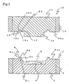
- the mold according to one embodiment of the present invention is comprised of a lower mold 5, which is a main mold molded in a molding flask 2, by a green sand molding method, using green sand 1.
- the lower mold has a concave portion 4 having the shape of a product, into which portion the amount of molten metal 3 that is required to produce a casting is poured.
- the mold has an upper mold 15, which is a main mold molded in a molding flask 12, by the green sand molding method, using green sand 11, and which has a convex portion 14, having the shape of the product, which portion forms a cavity that is required to produce a casting W.
- a structure A is formed so as to have certain clearances (gaps) between the press-fit portion F1 of the lower mold 5 and the press-fit portion F2 of the upper mold 15, such that it prevents molten metal from leaking onto the parting plane Pa formed by the parting plane P1a of the lower mold 5 and the parting plane P2a of the upper mold 15 when they overlap to produce a casting.
- Structure A which prevents the molten metal from leaking, comprises a protruding press-fit portion 6, protruding from the parting plane P1a, and formed along the outer circumference of the concave portion 4 of the lower mold 5, and a groove portion 16, formed on the upper mold 15, which portion fits with the protruding press-fit portion 6.
- press-fit portions F1 and F2 are the protruding press-fit portion 6 and the groove portion 16.
- the certain clearances are clearance ⁇ 1 in the horizontal direction, between the side face 6a of the protruding press-fit portion 6, and the side face 16a of the groove portion 16, which side face is a side face of a press-fit portion 17 positioned close to the outer circumference of the convex portion 14 of the upper mold 15, a clearance ⁇ 2 in the horizontal direction, between the other side face 6c of the protruding press-fit portion 6, and the other side face 16c of the groove portion 16, and a clearance ⁇ 3 in the vertical direction between the top face 6b of the protruding press-fit portion 6, and the bottom face 16b of the groove portion 16.
- These clearances are arranged so as to be in a range of from 0.1 to 4.0 mm.
- the protruding press-fit portion 6 is not limited to any particular shape, so long as it has a shape that surrounds the product along its circumference, or the outer periphery of a square, or the like. In one embodiment of the present invention, the protruding press-fit portion 6 is shown to have a round shape (ring).
- That shape is most effective in preventing a leakage of molten metal when the casting W has a circular shape in its periphery, as seen in Figs. 2 and 3 .
- a number of pins with a narrow spacing between them or a number of crescents spaced apart that form a ring shape can also be used.
- the shapes of the protruding press-fit portion 6 and the groove portion 16, according to the present invention are not particularly limited, if they have forms (for example, shapes and dimensions) that are functional, in the pressurized process, in preventing excess molten metal from leaking onto the parting plane Pa, a plane formed by the overlapping of the upper mold and the lower mold.
- the shapes of the protruding press-fit portion 6 and the groove portion 16 are made close to those of rectangles. These include a square, a trapezoid, and the like, in their cross section perpendicular to a parting plane P1a of the lower mold 5 and a parting plane P2a of the upper mold 15.
- the structure thus formed prevents excess molten metal 3 from leaking onto the parting plane Pa because the molten metal 3 either rises towards the upper mold or makes a detour if it should slip through clearances ⁇ 1 to ⁇ 3 formed by the overlapping of the upper mold 15 and the lower mold 5.
- the molten metal has reduced kinetic energy when it rises (makes a detour) toward the upper mold, and thus its leaking onto the parting plane is easily prevented.
- the height of the protruding press-fit portion 6 as measured from the parting plane P1a and the depth of the groove portion 16 as measured from the parting plane P2a are arranged so as to be in the range of from 5 to 50 mm, while each of the clearances ⁇ 1, ⁇ 2, and ⁇ 3 between the press-fit portion F1 of the lower mold 5 and the press-fit portion F2 of the upper mold 15 is appropriately secured. This is because it is feared that the molten metal 3 may pass through the clearances ⁇ 1, ⁇ 2 and ⁇ 3 and may leak onto the parting plane Pa if both the height and the depth were less than 5 mm. That height is insufficient for having the kinetic energy of the molten metal 3 reduced.
- both the height and the depth were more than 50 mm, a problem may arise, in molding a protruding press-fit portion and a groove portion. That is, because if a molding material is not appropriately filled in these areas, then the areas near the convex portion or the corner areas of the protruding press-fit portion and a groove portion may lack strength. Also, the widths of both the protruding press-fit portion 6 and the groove portion 16, while securing the clearances ⁇ 1, ⁇ 2, and ⁇ 3 between the press-fit portion F1 of the lower mold 5 and the press-fit portion F2 of the upper mold 15, are arranged so as to be in the range of 10 to 50 mm.
- a flow-off hollow (cavity) 18 can be formed on a press-fit portion 17 positioned close to the outer circumference of the convex portion 14 of the upper mold 15.
- the flow-off hollow 18, when formed, can prevent the molten metal from leaking onto or passing over the parting plane Pa and leaking out of the mold, by absorbing excess molten metal S1 that has been disadvantageously left unused, depending on the level of accuracy in the pouring of the pouring machine, from the area where the molten metal is finally poured in the pressurizing process.
- a total of 12 hollows are formed along the circumference of the press-fit portion 17, at equal intervals.
- the area ratio of the opening portion 18a of the flow-off hollow 18 to the split surface 17a of the casting W at the press-fit portion 17 of the upper mold 15 is preferably 1 to 20% per each of the flow-off hollows 18. This is because if the area ratio were to be more than 20%, the flow-off portion that became solidified in the flow-off hollow would be so thick that it is feared that the casting would suffer a broken casting if the flow-off portion were to be broken off. Also, the casting may be affected by a deformation of the shape at the corner areas of the casting W, where the molten metal is finally reached in the pressurizing process, because the pressurizing force cannot be sufficiently exerted on the molten metal.
- the ratio of the weight of the excess molten metal that enters the flow-off hollow 18 to the weight of the molten metal requires to produce the casting W is preferably 1 to 20% per each flow-off hollow 18. This is because if the ratio of the weight were to be more than 20%, an excessive pressure would be applied to the molten metal in a pressurizing process and a problem of penetration would occur with the portion of the casting W where the molten metal is finally reached.
- Structure A which prevents any leakage of molten metal, comprises a protruding press-fit portion 6 and a groove portion 16.
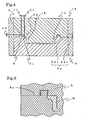
- Structure B is formed so as to prevent a leakage of molten metal by having, in the range of 5 to 50 mm, a step H between a split surface 33a of the casting W, at the press-fit portion 33, which is close to the circumference of the protruding portion 32 of the upper mold 31, and the parting plane P2b of the upper mold 31, which is at the outer circumference of the split surface 33a.
- structure B is simpler than Structure A.
- a step H is arranged so as to be in the range of from 5 to 50 mm. If H is less than 5 mm, molten metal may leak onto the parting plane because the height is too low to have the kinetic energy of the molten metal be reduced. If H is more than 50 mm, a casting may be affected by low strength of the convex portion and corner areas of the mold, depending on the complexity of the shapes of the concave portion or the convex portion of the casting, such that when a casting has a higher protrusion and a deeper concave portion the molding material may not be sufficiently filled when the casting is produced.
- a clearance between the press-fit portion F3 of the lower mold 21 and the press-fit portion F4 of the upper mold 31 is arranged so as to be in the range of from 0.1 to 4.0 mm.
- the press-fit portion F3 of the lower mold 21 of the present embodiment is the upper end (top) portion 22, which forms a parting plane P1 of the lower mold 21.
- the press-fit portion F4 of the upper mold 31 is a press-fit portion 33 of the upper mold 31.
- the clearance (gap) is in the horizontal direction between the inner side face 22a of the upper-end portion 22 and the press-fit side face 33b of the press-fit portion 33 of the upper mold 31.
- At least one flow-off hollow 34 can be formed on the press-fit portion 33 of the upper mold 31.
- the area ratio of the opening portion 34a of the flow-off hollow 34 formed on the press-fit portion 33 to the split surface 33a of the casting W at the press-fit portion 33 of the upper mold 31 is preferably 1 to 20%.
- the ratio of the weight of the excess molten metal that enters the flow-.off hollow 34 to the weight of the molten metal required to produce a casting is preferably 1 to 20%.
Landscapes
- Engineering & Computer Science (AREA)
- Mechanical Engineering (AREA)
- Molds, Cores, And Manufacturing Methods Thereof (AREA)
- Forging (AREA)
Applications Claiming Priority (2)
| Application Number | Priority Date | Filing Date | Title |
|---|---|---|---|
| JP2006281354A JP2008093727A (ja) | 2006-10-16 | 2006-10-16 | 鋳型 |
| PCT/JP2007/063059 WO2008047502A1 (en) | 2006-10-16 | 2007-06-22 | Mold |
Publications (2)
| Publication Number | Publication Date |
|---|---|
| EP2077922A1 EP2077922A1 (en) | 2009-07-15 |
| EP2077922B1 true EP2077922B1 (en) | 2011-08-17 |
Family
ID=38514284
Family Applications (1)
| Application Number | Title | Priority Date | Filing Date |
|---|---|---|---|
| EP07745563A Active EP2077922B1 (en) | 2006-10-16 | 2007-06-22 | Mold |
Country Status (11)
| Country | Link |
|---|---|
| US (1) | US8061409B2 (ru) |
| EP (1) | EP2077922B1 (ru) |
| JP (1) | JP2008093727A (ru) |
| KR (1) | KR20090088864A (ru) |
| CN (1) | CN101528387B (ru) |
| AT (1) | ATE520488T1 (ru) |
| BR (1) | BRPI0717611A2 (ru) |
| DE (1) | DE102007026295A1 (ru) |
| EA (1) | EA014212B1 (ru) |
| MX (1) | MX2009003951A (ru) |
| WO (1) | WO2008047502A1 (ru) |
Families Citing this family (15)
| Publication number | Priority date | Publication date | Assignee | Title |
|---|---|---|---|---|
| DE102008027682B4 (de) * | 2008-06-10 | 2011-03-17 | Eduard Heidt | Verfahren zum Herstellen von dünnwandigen und hochfesten Bauteilen |
| US20110084194A1 (en) * | 2009-09-24 | 2011-04-14 | Dgel Sciences | Cassette for biological analysis and method of making thereof |
| CN102139353A (zh) * | 2011-03-15 | 2011-08-03 | 中核苏阀横店机械有限公司 | 一种防漏铸型箱 |
| US8863817B2 (en) * | 2011-06-30 | 2014-10-21 | United Technologies Corporation | System and method for high temperature die casting tooling |
| WO2013016816A1 (en) * | 2011-08-04 | 2013-02-07 | Husky Injection Molding Systems Ltd. | A mold component having a residue cleaning feature |
| CN102935492B (zh) * | 2012-11-11 | 2014-12-10 | 骆驼集团华南蓄电池有限公司 | 对焊柱铸造模具 |
| US8985187B2 (en) | 2012-11-28 | 2015-03-24 | Palmer Manufacturing And Supply, Inc. | Auto-closer for centering and closing cope and drag sand mold halves |
| US9142530B2 (en) * | 2013-03-21 | 2015-09-22 | Stats Chippac Ltd. | Coreless integrated circuit packaging system and method of manufacture thereof |
| KR101340672B1 (ko) * | 2013-06-21 | 2013-12-12 | 심순식 | 주조용 주형의 정 위치 안내용 코어 어셈블리 및 이를 이용한 목형 |
| CN103447461A (zh) * | 2013-09-09 | 2013-12-18 | 梧州漓佳铜棒有限公司 | 一种带防溢凸台的铜阳极板浇铸模 |
| CN104308083B (zh) * | 2014-10-09 | 2018-07-17 | 北京时代锐智科技有限公司 | 减速箱盖的金属铸型及其加压铸造方法 |
| CN104439099A (zh) * | 2014-12-05 | 2015-03-25 | 沈阳工业大学 | 一种制备压缩机缸盖的悬压铸造法 |
| EP3549743B1 (en) | 2015-03-20 | 2022-08-24 | Husky Injection Molding Systems Ltd. | Mechanism for adjusting a shut height of a mold |
| CN106334784A (zh) * | 2016-09-07 | 2017-01-18 | 滁州市鑫鼎机械模具制造有限公司 | 一种用于制造冰箱压缩机铸造机架的铸造模具 |
| CN108215069B (zh) | 2016-12-14 | 2020-10-23 | 赫斯基注塑系统有限公司 | 对开式模具插入件以及模具堆叠 |
Family Cites Families (33)
| Publication number | Priority date | Publication date | Assignee | Title |
|---|---|---|---|---|
| US2633603A (en) * | 1950-06-28 | 1953-04-07 | Hiram N Huse | Mold |
| US3540516A (en) * | 1967-09-18 | 1970-11-17 | Kelsey Hayes Co | Method for making castings |
| US3968829A (en) * | 1971-06-25 | 1976-07-13 | Kabushiki Kaisha Akita | Molding apparatus with shielding mold member |
| CH607755A5 (ru) * | 1974-08-30 | 1978-10-31 | Inst Po Metalloznanie I Tekno | |
| JPS5650772A (en) * | 1979-09-28 | 1981-05-08 | Art Kinzoku Kogyo Kk | Metal mold unit for molten metal forging |
| JPS59206133A (ja) * | 1983-05-11 | 1984-11-21 | Nissan Motor Co Ltd | 鍛造部品の製造法 |
| CH675096A5 (ru) * | 1987-04-09 | 1990-08-31 | Uniport Theodor Hirzel | |
| US4775130A (en) * | 1987-07-23 | 1988-10-04 | Holdt J W Von | Mold with wear member |
| US4856977A (en) * | 1988-07-01 | 1989-08-15 | Holdt J W Von | Two stage mold centering system |
| US4986944A (en) * | 1988-10-31 | 1991-01-22 | Husky Injection Molding Systems Ltd. | Anti-collision method and apparatus for an injection mold |
| US5068065A (en) * | 1990-07-31 | 1991-11-26 | Galic Maus Ventures | Faster cycling sprue method and apparatus for injection molding plastic optical disks |
| DE4142410C2 (de) * | 1991-12-20 | 2000-11-09 | Gao Ges Automation Org | Vorrichtung zum Herstellen von flachen Kunststoff-Formstücken, beispielsweise Ausweiskarten durch Spritzgießen |
| DE19515192C2 (de) * | 1994-04-25 | 1997-08-21 | Dainippon Printing Co Ltd | Verfahren zum Ausbilden eines Musters auf einem Artikel während dessen Spritzguß und Vorrichtung zu diesem Zweck |
| JPH08117966A (ja) * | 1994-10-25 | 1996-05-14 | Mitsui Mining & Smelting Co Ltd | 成形用金型の製造方法及び成形用金型鋳造装置 |
| US5620720A (en) * | 1994-11-29 | 1997-04-15 | Allergan | Cast molding of intraocular lenses |
| DK134295A (da) * | 1995-11-28 | 1997-05-29 | Formkon Aps | Fremgangsmåde til fremstilling af to- eller flerdelte støbeforme |
| JP2000263613A (ja) * | 1999-03-11 | 2000-09-26 | Asahi Chem Ind Co Ltd | 熱可塑性樹脂成形品の射出圧縮成形方法 |
| GB9906240D0 (en) * | 1999-03-19 | 1999-05-12 | Ocular Sciences Limited | Lens mould |
| US6468381B1 (en) * | 1999-06-01 | 2002-10-22 | Acushnet Company | Method of making a golf ball and golf ball compression mold |
| JP2002301558A (ja) * | 2001-04-06 | 2002-10-15 | Honda Motor Co Ltd | 鋳造用金型構造 |
| US20030067088A1 (en) * | 2001-10-09 | 2003-04-10 | Scolamiero Stephen K. | Method for making golf ball cores and apparatus for use therein |
| CN1410191A (zh) * | 2002-10-23 | 2003-04-16 | 黄祖国 | 上模重力压型薄壁金属铸造工艺 |
| GB0304148D0 (en) * | 2003-02-25 | 2003-03-26 | Concavex Ltd | Contact lens mould |
| US7481645B2 (en) * | 2003-06-27 | 2009-01-27 | Biosphere Industries, Llc | Method for use in baking articles of manufacture and mold for use in said method |
| JP2005052871A (ja) * | 2003-08-06 | 2005-03-03 | Sintokogio Ltd | 鋳造方法およびその鋳型 |
| FR2860445B1 (fr) * | 2003-10-06 | 2006-02-03 | Silva Serge Da | Procede de fabrication d'un moule et moule obtenu. |
| US6936213B1 (en) * | 2003-11-18 | 2005-08-30 | Sorensen Research And Development Trust | Adjustment of relative positions of machine components |
| GB2408960B (en) * | 2003-12-12 | 2008-01-30 | Nokia Corp | In-mould labelling |
| DE102004038852B4 (de) * | 2004-08-10 | 2006-06-29 | Webasto Ag | Spritzgießmaschine |
| CN100368108C (zh) * | 2004-11-22 | 2008-02-13 | 比亚迪股份有限公司 | 利用低熔点合金模具进行弯曲拉深的成型方法及其装置 |
| JP4628125B2 (ja) * | 2005-02-09 | 2011-02-09 | 日本プラスト株式会社 | 樹脂漏れ防止構造 |
| JP4643343B2 (ja) * | 2005-04-13 | 2011-03-02 | 東芝機械株式会社 | 型締装置 |
| EP1829631A3 (en) * | 2006-10-20 | 2007-10-31 | Sintokogio, Ltd. | A casting method to produce a casting and a press used for the casting method |
-
2006
- 2006-10-16 JP JP2006281354A patent/JP2008093727A/ja active Pending
-
2007
- 2007-06-06 DE DE102007026295A patent/DE102007026295A1/de not_active Ceased
- 2007-06-22 CN CN200780038110.5A patent/CN101528387B/zh active Active
- 2007-06-22 WO PCT/JP2007/063059 patent/WO2008047502A1/en active Application Filing
- 2007-06-22 BR BRPI0717611-2A patent/BRPI0717611A2/pt not_active IP Right Cessation
- 2007-06-22 MX MX2009003951A patent/MX2009003951A/es active IP Right Grant
- 2007-06-22 EP EP07745563A patent/EP2077922B1/en active Active
- 2007-06-22 US US12/444,086 patent/US8061409B2/en active Active
- 2007-06-22 AT AT07745563T patent/ATE520488T1/de not_active IP Right Cessation
- 2007-06-22 KR KR1020097008837A patent/KR20090088864A/ko not_active Application Discontinuation
- 2007-06-22 EA EA200970383A patent/EA014212B1/ru not_active IP Right Cessation
Also Published As
| Publication number | Publication date |
|---|---|
| US8061409B2 (en) | 2011-11-22 |
| WO2008047502A1 (en) | 2008-04-24 |
| ATE520488T1 (de) | 2011-09-15 |
| EA200970383A1 (ru) | 2009-08-28 |
| CN101528387B (zh) | 2011-06-08 |
| BRPI0717611A2 (pt) | 2013-03-26 |
| KR20090088864A (ko) | 2009-08-20 |
| CN101528387A (zh) | 2009-09-09 |
| EP2077922A1 (en) | 2009-07-15 |
| DE102007026295A1 (de) | 2007-10-18 |
| US20090321612A1 (en) | 2009-12-31 |
| JP2008093727A (ja) | 2008-04-24 |
| EA014212B1 (ru) | 2010-10-29 |
| MX2009003951A (es) | 2009-04-28 |
Similar Documents
| Publication | Publication Date | Title |
|---|---|---|
| EP2077922B1 (en) | Mold | |
| CN105215271B (zh) | 一种变速箱壳体铸件的组芯造型砂型结构及组芯造型方法 | |
| JP2008093727A5 (ru) | ||
| CN103586413B (zh) | 一种多型腔结构件的精密铸造方法 | |
| CN101618429A (zh) | 一种风力发电机轮毂铸件的铸造方法 | |
| EP2335844B1 (en) | Method of manufacturing casting for mold for molding tire | |
| CN107470592A (zh) | 一种覆砂冷铁结构及其制作工艺 | |
| CN107598085A (zh) | 球铁垫板的制造方法 | |
| CN111097876B (zh) | 在3d打印砂型施加冷铁的方法 | |
| JPH0757411B2 (ja) | 鋳型製造方法及び押湯模型 | |
| US3517729A (en) | Casting apparatus having aligning members in cope and drag | |
| JP3052723B2 (ja) | 内燃機関におけるシリンダブロックの冷却通路製造方法 | |
| US3429364A (en) | Method for casting separate annular castings | |
| US20080105398A1 (en) | Article For Multiple Core Stacking And Method Thereof | |
| CN205732835U (zh) | 排气塞 | |
| JP2511567B2 (ja) | 水車ランナの製造法および部品用鋳型 | |
| CN217595825U (zh) | 一种大型板状铸件防变形结构 | |
| US3393726A (en) | Method for making large precision die castings from cavityless casting molds | |
| CN214349517U (zh) | 薄壁平板盖类镁合金压铸件浇注系统 | |
| CA2494036C (en) | A method for casting objects with an improved riser arrangement | |
| KR20030089910A (ko) | 금형의 주조방법 | |
| JPS60196246A (ja) | 鋳型の製造方法 | |
| CN105728653A (zh) | 一种铁型覆砂铸造磨片的铸型结构和铸造磨片的方法 | |
| JPS6340283Y2 (ru) | ||
| JPH0847768A (ja) | 鋳造製品の局部硬化方法 |
Legal Events
| Date | Code | Title | Description |
|---|---|---|---|
| PUAI | Public reference made under article 153(3) epc to a published international application that has entered the european phase |
Free format text: ORIGINAL CODE: 0009012 |
|
| 17P | Request for examination filed |
Effective date: 20090312 |
|
| AK | Designated contracting states |
Kind code of ref document: A1 Designated state(s): AT BE BG CH CY CZ DE DK EE ES FI FR GB GR HU IE IS IT LI LT LU LV MC MT NL PL PT RO SE SI SK TR |
|
| 17Q | First examination report despatched |
Effective date: 20090828 |
|
| GRAP | Despatch of communication of intention to grant a patent |
Free format text: ORIGINAL CODE: EPIDOSNIGR1 |
|
| DAX | Request for extension of the european patent (deleted) | ||
| GRAS | Grant fee paid |
Free format text: ORIGINAL CODE: EPIDOSNIGR3 |
|
| GRAA | (expected) grant |
Free format text: ORIGINAL CODE: 0009210 |
|
| AK | Designated contracting states |
Kind code of ref document: B1 Designated state(s): AT BE BG CH CY CZ DE DK EE ES FI FR GB GR HU IE IS IT LI LT LU LV MC MT NL PL PT RO SE SI SK TR |
|
| REG | Reference to a national code |
Ref country code: GB Ref legal event code: FG4D |
|
| REG | Reference to a national code |
Ref country code: CH Ref legal event code: EP |
|
| REG | Reference to a national code |
Ref country code: IE Ref legal event code: FG4D |
|
| REG | Reference to a national code |
Ref country code: DE Ref legal event code: R096 Ref document number: 602007016595 Country of ref document: DE Effective date: 20111020 |
|
| REG | Reference to a national code |
Ref country code: NL Ref legal event code: VDEP Effective date: 20110817 |
|
| LTIE | Lt: invalidation of european patent or patent extension |
Effective date: 20110817 |
|
| PG25 | Lapsed in a contracting state [announced via postgrant information from national office to epo] |
Ref country code: FI Free format text: LAPSE BECAUSE OF FAILURE TO SUBMIT A TRANSLATION OF THE DESCRIPTION OR TO PAY THE FEE WITHIN THE PRESCRIBED TIME-LIMIT Effective date: 20110817 Ref country code: IS Free format text: LAPSE BECAUSE OF FAILURE TO SUBMIT A TRANSLATION OF THE DESCRIPTION OR TO PAY THE FEE WITHIN THE PRESCRIBED TIME-LIMIT Effective date: 20111217 Ref country code: NL Free format text: LAPSE BECAUSE OF FAILURE TO SUBMIT A TRANSLATION OF THE DESCRIPTION OR TO PAY THE FEE WITHIN THE PRESCRIBED TIME-LIMIT Effective date: 20110817 Ref country code: SE Free format text: LAPSE BECAUSE OF FAILURE TO SUBMIT A TRANSLATION OF THE DESCRIPTION OR TO PAY THE FEE WITHIN THE PRESCRIBED TIME-LIMIT Effective date: 20110817 Ref country code: PT Free format text: LAPSE BECAUSE OF FAILURE TO SUBMIT A TRANSLATION OF THE DESCRIPTION OR TO PAY THE FEE WITHIN THE PRESCRIBED TIME-LIMIT Effective date: 20111219 Ref country code: LT Free format text: LAPSE BECAUSE OF FAILURE TO SUBMIT A TRANSLATION OF THE DESCRIPTION OR TO PAY THE FEE WITHIN THE PRESCRIBED TIME-LIMIT Effective date: 20110817 |
|
| REG | Reference to a national code |
Ref country code: AT Ref legal event code: MK05 Ref document number: 520488 Country of ref document: AT Kind code of ref document: T Effective date: 20110817 |
|
| PG25 | Lapsed in a contracting state [announced via postgrant information from national office to epo] |
Ref country code: LV Free format text: LAPSE BECAUSE OF FAILURE TO SUBMIT A TRANSLATION OF THE DESCRIPTION OR TO PAY THE FEE WITHIN THE PRESCRIBED TIME-LIMIT Effective date: 20110817 Ref country code: SI Free format text: LAPSE BECAUSE OF FAILURE TO SUBMIT A TRANSLATION OF THE DESCRIPTION OR TO PAY THE FEE WITHIN THE PRESCRIBED TIME-LIMIT Effective date: 20110817 Ref country code: CY Free format text: LAPSE BECAUSE OF FAILURE TO SUBMIT A TRANSLATION OF THE DESCRIPTION OR TO PAY THE FEE WITHIN THE PRESCRIBED TIME-LIMIT Effective date: 20110817 Ref country code: AT Free format text: LAPSE BECAUSE OF FAILURE TO SUBMIT A TRANSLATION OF THE DESCRIPTION OR TO PAY THE FEE WITHIN THE PRESCRIBED TIME-LIMIT Effective date: 20110817 Ref country code: GR Free format text: LAPSE BECAUSE OF FAILURE TO SUBMIT A TRANSLATION OF THE DESCRIPTION OR TO PAY THE FEE WITHIN THE PRESCRIBED TIME-LIMIT Effective date: 20111118 Ref country code: PL Free format text: LAPSE BECAUSE OF FAILURE TO SUBMIT A TRANSLATION OF THE DESCRIPTION OR TO PAY THE FEE WITHIN THE PRESCRIBED TIME-LIMIT Effective date: 20110817 |
|
| PG25 | Lapsed in a contracting state [announced via postgrant information from national office to epo] |
Ref country code: BE Free format text: LAPSE BECAUSE OF FAILURE TO SUBMIT A TRANSLATION OF THE DESCRIPTION OR TO PAY THE FEE WITHIN THE PRESCRIBED TIME-LIMIT Effective date: 20110817 |
|
| PG25 | Lapsed in a contracting state [announced via postgrant information from national office to epo] |
Ref country code: CZ Free format text: LAPSE BECAUSE OF FAILURE TO SUBMIT A TRANSLATION OF THE DESCRIPTION OR TO PAY THE FEE WITHIN THE PRESCRIBED TIME-LIMIT Effective date: 20110817 Ref country code: SK Free format text: LAPSE BECAUSE OF FAILURE TO SUBMIT A TRANSLATION OF THE DESCRIPTION OR TO PAY THE FEE WITHIN THE PRESCRIBED TIME-LIMIT Effective date: 20110817 |
|
| PG25 | Lapsed in a contracting state [announced via postgrant information from national office to epo] |
Ref country code: EE Free format text: LAPSE BECAUSE OF FAILURE TO SUBMIT A TRANSLATION OF THE DESCRIPTION OR TO PAY THE FEE WITHIN THE PRESCRIBED TIME-LIMIT Effective date: 20110817 Ref country code: RO Free format text: LAPSE BECAUSE OF FAILURE TO SUBMIT A TRANSLATION OF THE DESCRIPTION OR TO PAY THE FEE WITHIN THE PRESCRIBED TIME-LIMIT Effective date: 20110817 |
|
| PLBE | No opposition filed within time limit |
Free format text: ORIGINAL CODE: 0009261 |
|
| STAA | Information on the status of an ep patent application or granted ep patent |
Free format text: STATUS: NO OPPOSITION FILED WITHIN TIME LIMIT |
|
| PG25 | Lapsed in a contracting state [announced via postgrant information from national office to epo] |
Ref country code: DK Free format text: LAPSE BECAUSE OF FAILURE TO SUBMIT A TRANSLATION OF THE DESCRIPTION OR TO PAY THE FEE WITHIN THE PRESCRIBED TIME-LIMIT Effective date: 20110817 |
|
| 26N | No opposition filed |
Effective date: 20120521 |
|
| REG | Reference to a national code |
Ref country code: DE Ref legal event code: R097 Ref document number: 602007016595 Country of ref document: DE Effective date: 20120521 |
|
| REG | Reference to a national code |
Ref country code: DE Ref legal event code: R084 Ref document number: 602007016595 Country of ref document: DE Effective date: 20120809 |
|
| PG25 | Lapsed in a contracting state [announced via postgrant information from national office to epo] |
Ref country code: MC Free format text: LAPSE BECAUSE OF NON-PAYMENT OF DUE FEES Effective date: 20120630 |
|
| REG | Reference to a national code |
Ref country code: CH Ref legal event code: PL |
|
| REG | Reference to a national code |
Ref country code: CH Ref legal event code: PL |
|
| GBPC | Gb: european patent ceased through non-payment of renewal fee |
Effective date: 20120622 |
|
| REG | Reference to a national code |
Ref country code: IE Ref legal event code: MM4A |
|
| REG | Reference to a national code |
Ref country code: FR Ref legal event code: ST Effective date: 20130228 |
|
| PG25 | Lapsed in a contracting state [announced via postgrant information from national office to epo] |
Ref country code: FR Free format text: LAPSE BECAUSE OF NON-PAYMENT OF DUE FEES Effective date: 20120702 Ref country code: ES Free format text: LAPSE BECAUSE OF FAILURE TO SUBMIT A TRANSLATION OF THE DESCRIPTION OR TO PAY THE FEE WITHIN THE PRESCRIBED TIME-LIMIT Effective date: 20111128 Ref country code: LI Free format text: LAPSE BECAUSE OF NON-PAYMENT OF DUE FEES Effective date: 20120630 Ref country code: IE Free format text: LAPSE BECAUSE OF NON-PAYMENT OF DUE FEES Effective date: 20120622 Ref country code: GB Free format text: LAPSE BECAUSE OF NON-PAYMENT OF DUE FEES Effective date: 20120622 Ref country code: CH Free format text: LAPSE BECAUSE OF NON-PAYMENT OF DUE FEES Effective date: 20120630 |
|
| PG25 | Lapsed in a contracting state [announced via postgrant information from national office to epo] |
Ref country code: BG Free format text: LAPSE BECAUSE OF FAILURE TO SUBMIT A TRANSLATION OF THE DESCRIPTION OR TO PAY THE FEE WITHIN THE PRESCRIBED TIME-LIMIT Effective date: 20111117 |
|
| PG25 | Lapsed in a contracting state [announced via postgrant information from national office to epo] |
Ref country code: MT Free format text: LAPSE BECAUSE OF FAILURE TO SUBMIT A TRANSLATION OF THE DESCRIPTION OR TO PAY THE FEE WITHIN THE PRESCRIBED TIME-LIMIT Effective date: 20110817 |
|
| PG25 | Lapsed in a contracting state [announced via postgrant information from national office to epo] |
Ref country code: TR Free format text: LAPSE BECAUSE OF FAILURE TO SUBMIT A TRANSLATION OF THE DESCRIPTION OR TO PAY THE FEE WITHIN THE PRESCRIBED TIME-LIMIT Effective date: 20110817 |
|
| PG25 | Lapsed in a contracting state [announced via postgrant information from national office to epo] |
Ref country code: LU Free format text: LAPSE BECAUSE OF NON-PAYMENT OF DUE FEES Effective date: 20120622 |
|
| PG25 | Lapsed in a contracting state [announced via postgrant information from national office to epo] |
Ref country code: HU Free format text: LAPSE BECAUSE OF FAILURE TO SUBMIT A TRANSLATION OF THE DESCRIPTION OR TO PAY THE FEE WITHIN THE PRESCRIBED TIME-LIMIT Effective date: 20070622 |
|
| PGFP | Annual fee paid to national office [announced via postgrant information from national office to epo] |
Ref country code: DE Payment date: 20230620 Year of fee payment: 17 |
|
| PGFP | Annual fee paid to national office [announced via postgrant information from national office to epo] |
Ref country code: IT Payment date: 20230623 Year of fee payment: 17 |