EP2075889B1 - Elektrisches Installationsgerät - Google Patents
Elektrisches Installationsgerät Download PDFInfo
- Publication number
- EP2075889B1 EP2075889B1 EP08021986.8A EP08021986A EP2075889B1 EP 2075889 B1 EP2075889 B1 EP 2075889B1 EP 08021986 A EP08021986 A EP 08021986A EP 2075889 B1 EP2075889 B1 EP 2075889B1
- Authority
- EP
- European Patent Office
- Prior art keywords
- installation device
- fastener
- preceding patent
- elements
- front element
- Prior art date
- Legal status (The legal status is an assumption and is not a legal conclusion. Google has not performed a legal analysis and makes no representation as to the accuracy of the status listed.)
- Not-in-force
Links
Images


Classifications
-
- H—ELECTRICITY
- H01—ELECTRIC ELEMENTS
- H01R—ELECTRICALLY-CONDUCTIVE CONNECTIONS; STRUCTURAL ASSOCIATIONS OF A PLURALITY OF MUTUALLY-INSULATED ELECTRICAL CONNECTING ELEMENTS; COUPLING DEVICES; CURRENT COLLECTORS
- H01R13/00—Details of coupling devices of the kinds covered by groups H01R12/70 or H01R24/00 - H01R33/00
- H01R13/44—Means for preventing access to live contacts
- H01R13/447—Shutter or cover plate
-
- H—ELECTRICITY
- H01—ELECTRIC ELEMENTS
- H01R—ELECTRICALLY-CONDUCTIVE CONNECTIONS; STRUCTURAL ASSOCIATIONS OF A PLURALITY OF MUTUALLY-INSULATED ELECTRICAL CONNECTING ELEMENTS; COUPLING DEVICES; CURRENT COLLECTORS
- H01R2103/00—Two poles
-
- H—ELECTRICITY
- H01—ELECTRIC ELEMENTS
- H01R—ELECTRICALLY-CONDUCTIVE CONNECTIONS; STRUCTURAL ASSOCIATIONS OF A PLURALITY OF MUTUALLY-INSULATED ELECTRICAL CONNECTING ELEMENTS; COUPLING DEVICES; CURRENT COLLECTORS
- H01R24/00—Two-part coupling devices, or either of their cooperating parts, characterised by their overall structure
- H01R24/76—Two-part coupling devices, or either of their cooperating parts, characterised by their overall structure with sockets, clips or analogous contacts and secured to apparatus or structure, e.g. to a wall
- H01R24/78—Two-part coupling devices, or either of their cooperating parts, characterised by their overall structure with sockets, clips or analogous contacts and secured to apparatus or structure, e.g. to a wall with additional earth or shield contacts
Definitions
- the invention relates to an electrical installation device according to the preamble of claim 1,
- sockets are used as part of the building installation technology and usually mounted stationary. Depending on the application and purpose, these sockets are often provided with lids to prevent the ingress of foreign bodies and also to prevent unauthorized access.
- US-B1-6545218 discloses an installation device according to the preamble of claim 1.
- the DE 429 630 C shows an incandescent lamp socket, which is closable with a closure in the form of an iris diaphragm. From the US 4 217 019 A is an electrical connector known, the coupling with a closure in the form of an iris diaphragm is closed.
- the object of the present invention is therefore to eliminate the above-mentioned disadvantages and to provide an installation device which is formed lockable and flat construction.
- the invention according to claim 1 has an installation device with a closure which is integrated in a front element and thus formed flat construction. When closed, a nearly flush surface is created between the front element and the closure.
- the shutter opens and closes in the plane of the front element.
- Closure elements are mounted and guided on the edge side in the front element and radially surround a central region, preferably a receiving space in the form of a socket pot. There is no additional space in front of or behind the front element needed much more the shutter integrated into the existing structure by optimizing the space and component layout.
- the closure has a plurality of closure elements which extend in the plane of the front element and are each arranged to be movable about a fixed bearing. In this case, the closure elements move radially inward or outward relative to the center of the front element.
- the individual closure elements are mechanically coupled to ensure a proper movement of the closure elements when opening and closing the closure.
- the closure elements are preferably guided in a surrounding guide element, wherein pins of the closure elements slide in slot-like grooves of the guide element.
- the closure can either be moved directly at the front by handling elements on the front element or by automatisms which drive the closure at a central location, for example via a gear in conjunction with the guide element.
- the closure mechanism is electrically driven by means of a correspondingly small electric motor.
- the electrical system can be activated in different ways, for example directly by means of a function key on the installation device or remotely operable.
- wireless functionalities for example radio or IR components, are conceivable here.
- An advantage is a sensory detection of approaching metals, eg. As the pins of a device plug, thereby causing an automatic opening of the closure.
- an authorization query is possible, so that only by means of special access parameters, such as transponder signals or numerical codes, an opening of the shutter Practically exist therefore differently equipped front elements that can be used depending on the application.
- the front elements including the closure elements can be seamlessly adapted to the surfaces of the environment by means of correspondingly designed surfaces and thus integrated. Also conceivable are informative inscriptions and imprints of the closure elements.
- an installation device 1 in the form of a socket is shown, which is fastened in an installation housing 2, which is fixed in a fixed position in a building wall 3.
- the socket 1 has a device base 4, the outside a support frame 5 surrounds, which allows the attachment of the socket 1 in the installation housing 2 Front side, a front element 6 is fixed, in which a receiving space 7 is formed for a device connector 8 and depending on the application may be one or more parts in the device base 4 terminals 9 and associated metallic contact elements are arranged in the front side connecting contacts 10 of the device connector 8 are inserted.
- an unillustrated grounding bracket is arranged in the device base 4, which serves for the front-side contacting of a grounding contact of the device connector 8.
- a wall-mounted supply line 11 supplies the socket 1 with a mains voltage, wherein the individual lines 12 are releasably fixed in the terminals 9. ( FIG. 1 )
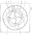
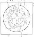
- FIGS. 2a-f an interior view of a front element 6 is shown, so that the components of an integrated closure 13 are visible.
- the closure 13 has a plurality of closure elements 14, which extend in the plane of the front element 6 and are wing-like.
- the closure elements 14 are each arranged to be movable about a fixed bearing 15 and are mechanically coupled in order to ensure a proper sequence of movements during the opening and closing of the closure 13.
- the closure elements 14 are guided in a surrounding guide element 16, wherein pin 17 of the closure elements 14 in slot-like grooves 18 of the guide element 16 slide.
- the guide element 16 is annular and dented in some places.
- a prestressed spring 19 acts on the guide element 16 in order to enable a nearly automatic opening or closing of the closure 13 or to secure the opening position after a first movement pulse.
- an opening cycle of the shutter 13 is to be followed.
- a nearly flush surface between front element 6 and closure 13 is formed.
- the closure elements 14 guided by the guide element 16 move uniformly radially outward relative to the center of the front element 6 and release the socket 7 so that a device plug 8 is inserted can be.
- the proper movement of the closure elements 14 ensures the surrounding guide element 16, wherein the pins 17 of the closure elements 14 slide in the grooves 18.
- a nearly flush surface is created between the front element 6 and the closure 13.
- the closure elements 14 are located completely peripherally in the front element 6 and radially surround the sockets 7.
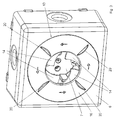
- FIG. 3 an embodiment of a surface-mounted installation is shown, in which case in particular handling elements 20 are visible, which allow a front-side manual movement of the closure 13.
- Other embodiments not shown arise in particular by automatic mechanisms that drive the closure 13 at a central location, for example via a gear in conjunction with the guide member 16.
Landscapes
- Connector Housings Or Holding Contact Members (AREA)
- Details Of Connecting Devices For Male And Female Coupling (AREA)
- Casings For Electric Apparatus (AREA)
- Operating, Guiding And Securing Of Roll- Type Closing Members (AREA)
Description
- Die Erfindung betrifft ein elektrisches Installationsgerät nach dem Oberbegriff des Patentanspruches 1,
- Elektrische Installationsgeräte in Form von Steckdosen werden im Rahmen der Gebäudeinstallationstechnik eingesetzt und in der Regel ortsfest montiert. In Abhängigkeit von dem Einsatzgebiet und ¬zweck werden diese Steckdosen oftmals mit Deckeln versehen, um das Eindringen von Fremdkörpern zu vermeiden und darüber hinaus auch um einen unberechtigten Zugriff zu verhindern.
- Aus dem Stand der Technik sind vielfältige Lösungen bekannt, um mit einem Deckel die Öffnung des Steckdosentopfes zu erschließen. Aus der
EP 0 786 833 B1 ist es beispielsweise bekannt, gelenkig angeordnete Klappdeckel zu verwenden. Darüber hinaus sind separate Verschlusseinsätze bekannt. - Nachteilig ist bei diesen Lösungen, dass die Deckel sowohl in der Verschlussposition als auch in der Öffnungsposition über die übrigen Bauteile des Installationsgerätes, beispielsweise der Zentralplatte oder dem Rahmen, vorstehen. Allgemein besteht das Bedürfnis eine verschließbare aber möglichst flache Baueinheit zu haben, wobei insbesondere im Wohnbereich zusätzlich optisch ansprechende Lösungen erwünscht sind.
- Aus der
DE 87 08 617 U1 und aus derWO 03/096486 A1 -
US-B1-6545218 offenbart ein Installationsgerät nach dem Oberbegriff des Anspruchs 1. - Die
DE 429 630 C zeigt eine Glühlampenfassung, die mit einem Verschluss in Form einer Irisblende verschließbar ist. Aus derUS 4 217 019 A ist eine elektrische Steckverbindung bekannt, dessen Kupplung mit einem Verschluss in Form einer Irisblende verschließbar ist. - Die Aufgabe der vorliegenden Erfindung besteht deshalb darin, die vorstehend genannten Nachteile zu beseitigen und ein Installationsgerät zu schaffen, das verschließbar und flachbauend ausgebildet ist.
- Gelöst wird diese Aufgabe durch die im Patentanspruch 1 angegebenen Merkmale. Vorteilhafte Ausgestaltungen ergeben sich aus den Unteransprüchen.
- Die Erfindung gemäß dem Patentanspruch 1 weist ein Installationsgerät mit einem Verschluss auf, der in ein Frontelement integriert ist und damit flachbauend ausgebildet ist. Im geschlossenen Zustand entsteht eine nahezu flächenbündige Oberfläche zwischen Frontelement und Verschluss. Der Verschluss öffnet und schließt in der Ebene des Frontelementes. Verschlusselemente sind randseitig in dem Frontelement gelagert und geführt und umgeben radial einen mittleren Bereich, vorzugsweise einen Aufnahmeraum in Form eines Steckdosentopfes. Es wird kein zusätzlicher Platz vor oder hinter dem Frontelement benötigt Vielmehr wird der Verschluss durch Optimierung des Raumes und der Bauteilanordnung in die vorhandene Struktur integriert.
- Der Verschluss weist mehrere Verschlusselemente auf, die sich in der Ebene des Frontelementes erstrecken und jeweils um ein Festlager bewegbar angeordnet sind. Dabei bewegen sich die Verschlusselemente radial ein- oder auswärts gegenüber dem Mittelpunkt des Frontelementes. Die einzelnen Verschlusselemente sind mechanisch gekoppelt, um einen ordnungsgemäßen Bewegungsablauf der Verschlusselemente beim Öffnen und Schließen des Verschlusses zu gewährleisten. Vorzugsweise sind die Verschlusselemente hierzu in einem sie umgebenden Führungselement geführt, wobei Zapfen der Verschlusselemente in kulissenartigen Nuten des Führungselementes gleiten.
- Der Verschluss kann entweder frontseitig direkt durch Handhabungselemente an dem Frontelement bewegt werden oder durch Automatismen, die an einer zentralen Stelle, beispielsweise über ein Getriebe in Verbindung mit dem Führungselement, den Verschluss antreiben. Neben dem manuell zu bedienenden Verschluss existiert eine Ausführung, bei der die Verschlussmechanik mittels eines entsprechend kleinen Elektromotors elektrisch angetrieben wird. Je nach Ausführung lässt sich die Elektrik auf unterschiedliche Weise aktivieren, beispielsweise direkt mittels einer Funktionstaste am Installationsgerät oder fernbedienbar. Denkbar sind hier vor allem drahtlose Funktionalitäten beispielsweise Funk- oder IR-Komponenten. Von Vorteil ist eine sensorische Erfassung sich nähernder Metalle, z. B. der Kontaktstifte eines Gerätesteckers, um hierdurch eine automatische Öffnung des Verschlusses zu bewirken. Darüber hinaus ist auch eine Berechtigungsabfrage möglich, so dass nur mittels spezieller Zugangsparameter, beispielsweise Transpondersignale oder Zahlencodes, eine Öffnung des Verschlusses erfolg Praktischerweise existieren deshalb unterschiedlich ausgestattete Frontelemente, die je nach Anwendungsfall einsetzbar sind.
- In einer besonders vorteilhaften Ausführung lassen sich die Frontelemente einschließlich der Verschlusselemente durch entsprechend gestaltete Oberflächen nahtlos an die Oberflächen der Umgebung anpassen und damit integrieren. Denkbar sind auch informative Beschriftungen und Bedruckungen der Verschlusselemente.
- Es wird ein universell verwendbares Frontelenent geschaffen, mit dem im Bedarfsfall bestehende Installationsgeräte umgerüstet werden können. Wesentlich ist dabei, dass zur Aufrüstung des Installationggerätes lediglich das gerätespezifische Frontelement ausgetauscht werden muss. Eine Demontage des Gerätesockels bzw. des Tragrahmens ist nicht notwendig. Die vorhandene Geometrie der Gerätesockel kann unverändert genutzt werden, da die Befestigungspunkte und Kontaktpunkte erhalten bleiben.
- Weitere Einzelheiten, Merkmale und Vorteile der Erfindung ergeben sich aus nachfolgender Beschreibung eines bevorzugten Ausführungsbeispieles anhand der Zeichnungen.
- Es zeigen:
- Figur 1
- einen schematischen Aufbau eines Installationsgerätes.
- Figur 2a-f
- schematisch den Aufbau eines Frontelementes des Installationsgerätes und einen Öffnungszyklus eines Verschlusses.
- Figur 3
- eine perspektivische Ansicht einer Aufputzanordnung mit halb geöffnetem Verschluss und Handhabungselementen.
- Gleiche oder gleichwirkende Bauteile sind in der nachfolgenden Beschreibung mit gleichen Bezugszeichen versehen.
- Nachfolgend wird der Aufbau und die Funktionsweise des erfindungsgemäßen Installationsgerätes 1 näher beschrieben. Beispielhaft ist dabei ein Installationsgerät 1 in Form einer Steckdose dargestellt, die in einem Installationsgehäuse 2 befestigt ist, welches ortsfest in einer Gebäudewand 3 fixiert ist. Die Steckdose 1 weist einen Gerätesockel 4 auf, den außenseitig ein Tragrahmen 5 umgibt, der die Befestigung der Steckdose 1 in dem Installationsgehäuse 2 ermöglicht Frontseitig ist ein Frontelement 6 befestigt, in dem ein Aufnahmeraum 7 für einen Gerätestecker 8 ausgebildet ist und das je nach Anwendung ein- oder mehrteilig sein kann In dem Gerätesockel 4 sind Anschlussklemmen 9 und damit verbundene metallische Kontaktelemente angeordnet, in die frontseitig Anschlusskontakte 10 des Gerätesteckers 8 gesteckt werden. Des weiteren ist in dem Gerätesockel 4 ein nicht dargestellter Erdungsbügel angeordnet, der zur frontseitigen Kontaktierung eines Erdungskontaktes des Gerätesteckers 8 dient. Eine wandseitig verlegte Versorgungsleitung 11 versorgt die Steckdose 1 mit einer Netzspannung, wobei die einzelnen Leitungen 12 lösbar in den Anschlussklemmen 9 fixiert sind. (
Figur 1 ) - In den
Figuren 2a-f ist eine Innenansicht eines Frontelementes 6 dargestellt, so dass die Bauteile eines darin integrierten Verschlusses 13 sichtbar sind. Der Verschluss 13 weist mehrere Verschlusselemente 14 auf, die sich in der Ebene des Frontelementes 6 erstrecken und flügelartig ausgebildet sind. Die Verschlusselemente 14 sind jeweils um ein Festlager 15 bewegbar angeordnet und mechanisch gekoppelt, um einen ordnungsgemäßen Bewegungsablauf beim Öffnen und Schließen des Verschlusses 13 zu gewährleisten. Hierzu sind die Verschlusselemente 14 in einem sie umgebenden Führungselement 16 geführt, wobei Zapfen 17 der Verschlusselemente 14 in kulissenartigen Nuten 18 des Führungselementes 16 gleiten. Das Führungselement 16 ist ringförmig ausgebildet und an einigen Stellen eingebeult. Eine vorgespannte Feder 19 greift an dem Führungselement 16 an, um nach einem ersten Bewegungsimpuls eine nahezu automatische Öffnung oder Schließung des Verschlusses 13 zu ermöglichen bzw. die Öffnungsposition zu sichern. - Anhand der
Figuren 2a-f ist ein Öffnungszyklus des Verschlusses 13 zu verfolgen. Im geschlossenen Zustand entsteht eine nahezu flächenbündige Oberfläche zwischen Frontelement 6 und Verschluss 13. Bei der Öffnung bewegen sich die Verschlusselemente 14 geführt durch das Führungselement 16 gleichmäßig radial auswärts gegenüber dem Mittelpunkt des Frontelementes 6 und geben den Steckdosentopf 7 frei, so dass ein Gerätestecker 8 eingeführt werden kann. Den ordnungsgemäßen Bewegungsablauf der Verschlusselemente 14 gewährleistet das umgebende Führungselement 16, wobei die Zapfen 17 der Verschlusselemente 14 in den Nuten 18 gleiten. Im geschlossenen Zustand entsteht eine nahezu flächenbündige Oberfläche zwischen Frontelement 6 und Verschluss 13. Die Verschlusselemente 14 befinden sich vollständig randseitig in dem Frontelement 6 und umgeben radial den Steckdosentopf 7. - In
Figur 3 ist ein Ausführungsbeispiel einer Aufputzinstallation dargestellt, wobei hier insbesondere Handhabungselemente 20 sichtbar sind, die eine frontseitige manuelle Bewegung des Verschlusses 13 ermöglichen. Weitere nicht dargestellte Ausführungen ergeben sich insbesondere durch Automatismen, die an einer zentralen Stelle, beispielsweise über ein Getriebe in Verbindung mit dem Führungselement 16, den Verschluss 13 antreiben. - Die vorstehende Beschreibung des Ausführungsbeispieles dient nur zu illustrativen Zwecken und nicht zum Zwecke der Beschränkung der Erfindung.
Claims (9)
- Installationsgerät (1) bestehend aus einem Gerätesockel (4) aus einem an dem Gerätesockel (4) befestigten Tragrahmen (5), und aus einem Frontelement (6) wobei an einer Rückseite des Gerätesockels (4) Leitungen (12) an schließbar sind und wobei an einer Frontseite des Gerätesockels (4) das Frontelement (6) befestigt ist, wobei in das Frontelement (6) ein Verschluss (13) integriert ist, der in der Ebene des Frontelementes (6) bewegbar ist, wobei der Verschluss (13) mehrere Verschlusselemente (14) aufweist, dadurch gekennzeichnet, dass die Verschlusselemente radial einen Aufnahmeraum (7) umgeben und jeweils um ein Festlager (15) bewegbar angeordnet sind, wobei die Verschlusselemente (14) einwärts und/oder auswärts gegenüber dem Mittelpunkt des Frontelementes (6) bewegbar sind.
- Installationsgerät nach einem der vorhergehenden Patentansprüche, dadurch gekennzeichnet, dass die Verschlusselemente (14) mechanisch gekoppelt sind.
- Installationsgerät nach einem der vorhergehenden Patentansprüche, dadurch gekennzeichnet, dass die Verschlusselemente (14) in einem umgebenden Führungselement (16) kulissenartig geführt sind.
- Installationsgerät nach einem der vorhergehenden Patentansprüche, dadurch gekennzeichnet, dass der Verschluss (13) manuell mittels an dem Frontelement (6) ausgebildeten Handhabungselementen (20) betätigbar ist.
- Installationsgerät nach einem der vorhergehenden Patentansprüche, dadurch gekennzeichnet, dass die Verschlusselemente (14) an einer zentralen Stelle antreibbar sind.
- Installationsgerät nach einem der vorhergehenden Patentansprüche, dadurch gekennzeichnet, dass der Verschluss (13) durch eine Feder (19) automatisch öffnet und schließt.
- Installationsgerät nach einem der vorhergehenden Patentansprüche, dadurch gekennzeichnet, dass der Verschluss (13) durch einen Elektromotor antreibbar ist.
- Installationsgerät nach einem der vorhergehenden Patentansprüche, dadurch gekennzeichnet, dass der Elektromotor durch Knopf oder per Fernauslösung aktivierbar ist.
- Installationsgerät nach einem der vorhergehenden Patentansprüche, dadurch gekennzeichnet, dass der Verschluss (13) durch sensorische Erfassung von Metallen aktiviert wird.
Applications Claiming Priority (1)
| Application Number | Priority Date | Filing Date | Title |
|---|---|---|---|
| DE102007063585A DE102007063585B4 (de) | 2007-12-29 | 2007-12-29 | Elektrisches Installationsgerät |
Publications (3)
| Publication Number | Publication Date |
|---|---|
| EP2075889A2 EP2075889A2 (de) | 2009-07-01 |
| EP2075889A3 EP2075889A3 (de) | 2011-04-13 |
| EP2075889B1 true EP2075889B1 (de) | 2016-08-24 |
Family
ID=40548840
Family Applications (1)
| Application Number | Title | Priority Date | Filing Date |
|---|---|---|---|
| EP08021986.8A Not-in-force EP2075889B1 (de) | 2007-12-29 | 2008-12-18 | Elektrisches Installationsgerät |
Country Status (4)
| Country | Link |
|---|---|
| EP (1) | EP2075889B1 (de) |
| DE (1) | DE102007063585B4 (de) |
| DK (1) | DK2075889T3 (de) |
| ES (1) | ES2603224T3 (de) |
Families Citing this family (21)
| Publication number | Priority date | Publication date | Assignee | Title |
|---|---|---|---|---|
| DE102009044343A1 (de) | 2009-10-28 | 2011-05-05 | Amad - Mennekes Holding Gmbh & Co. Kg | Steckvorrichtung mit Verschlusseinrichtung |
| EP2410625B1 (de) * | 2010-07-21 | 2014-11-26 | Schneider Electric Industries SAS | Manipulationssichere Steckdosenanordnung |
| US8845345B2 (en) | 2011-03-16 | 2014-09-30 | Amad Mennekes Holding Gmbh & Co. Kg | Electrical plug-in device with closure device |
| EP2608335B1 (de) * | 2011-12-22 | 2014-09-24 | Bachmann Technology GmbH & Co. KG | Einbaugehäuse |
| ES2548186T3 (es) * | 2012-06-14 | 2015-10-14 | Scame Parre S.P.A. | Conexión de corriente industrial de tipo hembra, con dispositivo de protección de los contactos bajo tensión |
| DE102013000829B4 (de) * | 2013-01-18 | 2015-03-12 | Maximilian Rüttiger | Kabeldurchführung |
| CN105351545B (zh) * | 2015-12-09 | 2017-12-22 | 长沙盛泓机械有限公司 | 大曲生产线用圆形下料阀 |
| DE102018009948B4 (de) * | 2018-12-13 | 2026-04-16 | Bachmann Gmbh | Installationselement für Steckdosenelemente |
| DE102019121073A1 (de) * | 2019-08-05 | 2021-02-11 | Köra-Packmat Maschinenbau GmbH | Verschlussvorrichtung für eine gasführende Leitung |
| DE102019128509A1 (de) * | 2019-10-22 | 2021-04-22 | Volkswagen Aktiengesellschaft | Verschlusssystem für einen Hochvolt-Anschluss |
| DE102020002945B3 (de) | 2020-05-18 | 2021-07-29 | Berthold Kalkus | Installationselement |
| WO2022135631A1 (de) | 2020-12-21 | 2022-06-30 | Bachmann Gmbh | Einbaugehäuse; verfahren zur bedienung eines einbaugehäuses |
| DE102021106039A1 (de) | 2020-12-21 | 2022-06-23 | Bachmann Gmbh | Einbaugehäuse; Verfahren zur Bedienung eines Einbaugehäuses |
| DE102021106043A1 (de) | 2021-02-08 | 2022-08-11 | Bachmann Gmbh | Dosengehäuse; Verfahren zur Bedienung eines Dosengehäuses |
| EP4289031B1 (de) | 2021-02-08 | 2026-04-29 | Bachmann GmbH | Dosengehäuse; verfahren zur bedienung eines dosengehäuses |
| WO2022167039A1 (de) | 2021-02-08 | 2022-08-11 | Bachmann Gmbh | Dosengehäuse; verfahren zur bedienung eines dosengehäuses |
| DE102021106042A1 (de) | 2021-02-08 | 2022-08-11 | Bachmann Gmbh | Dosengehäuse; Verfahren zur Bedienung eines Dosengehäuses |
| DE102021107848B4 (de) | 2021-03-29 | 2026-01-22 | Bachmann Gmbh | Dosengehäuse; Verfahren zur Bedienung eines Dosengehäuses |
| CN115031028B (zh) * | 2022-07-07 | 2025-10-31 | 安徽汉威环境科技有限公司 | 一种旋转闭合闸 |
| DE102024115508B4 (de) * | 2023-10-31 | 2025-08-21 | Bachmann Gmbh | Dosengehäuse; Verfahren zur Bedienung eines Dosengehäuses |
| EP4550598A1 (de) | 2023-10-31 | 2025-05-07 | Bachmann GmbH | Dosengehäuse; verfahren zur bedienung eines dosengehäuses |
Family Cites Families (15)
| Publication number | Priority date | Publication date | Assignee | Title |
|---|---|---|---|---|
| DE429630C (de) * | 1924-09-25 | 1926-05-31 | Friedrich Breitlaender | Gluehlampenfassung mit verlaengertem Fassungsmantel zum Schutz gegen Beruehrung stromfuehrender Teile |
| DE1837279U (de) * | 1961-02-24 | 1961-09-07 | Kurt Rath | Elektrischer, fuer die lueftung geschlossener raeume dienender ventilator. |
| DE2060966A1 (de) * | 1970-12-11 | 1972-06-29 | Bbc Brown Boveri & Cie | Elektrisches Installationsgeraet mit Deckel |
| US4217019A (en) * | 1976-11-19 | 1980-08-12 | Bunker Ramo Corporation | EMI protected connector assembly |
| DE8708617U1 (de) * | 1987-06-20 | 1987-09-03 | Spiegeler, Jakob, 5630 Remscheid | Sicherheits-Steckdose |
| DE29601440U1 (de) | 1996-01-29 | 1997-05-28 | Dehn + Söhne GmbH + Co KG, 90489 Nürnberg | Steckdose mit einem Modul für Zusatzfunktionen |
| RU2109192C1 (ru) * | 1996-03-21 | 1998-04-20 | Александр Леонидович Кузьмин | Запорное устройство |
| DE19631496A1 (de) * | 1996-08-03 | 1998-02-05 | Merten Gmbh & Co Kg Geb | Elektrische Steckdose mit Kindersicherung |
| US6050834A (en) * | 1998-12-21 | 2000-04-18 | The United States Of America As Represented By The Secretary Of The Navy | Electrical outlet splash protector |
| DE10155502A1 (de) * | 2001-11-13 | 2003-05-22 | Abb Patent Gmbh | Elektrisches Installationsgerät mit Schiebedeckel |
| KR200276531Y1 (ko) * | 2002-03-08 | 2002-05-24 | 이덕현 | 콘센트 안전장치 |
| US6545218B1 (en) * | 2002-05-14 | 2003-04-08 | Donald J. Blaess | Safety cover for dual electrical wall mounted outlets |
| DE10246654B3 (de) * | 2002-10-07 | 2004-04-15 | Chao-Chi Wang | Steckdose |
| US7438567B2 (en) * | 2004-12-28 | 2008-10-21 | Belkin International Inc. | Safety mechanism, electrical outlet containing same, and method of manufacturing same |
| DE102006058894A1 (de) * | 2005-12-21 | 2007-06-28 | Bachmann Gmbh & Co. Kg | Abdeckung für eine Anschlussdose |
-
2007
- 2007-12-29 DE DE102007063585A patent/DE102007063585B4/de not_active Expired - Fee Related
-
2008
- 2008-12-18 ES ES08021986.8T patent/ES2603224T3/es active Active
- 2008-12-18 EP EP08021986.8A patent/EP2075889B1/de not_active Not-in-force
- 2008-12-18 DK DK08021986.8T patent/DK2075889T3/en active
Also Published As
| Publication number | Publication date |
|---|---|
| DE102007063585B4 (de) | 2012-08-09 |
| DE102007063585A1 (de) | 2009-07-09 |
| EP2075889A3 (de) | 2011-04-13 |
| ES2603224T3 (es) | 2017-02-24 |
| DK2075889T3 (en) | 2016-12-05 |
| EP2075889A2 (de) | 2009-07-01 |
Similar Documents
| Publication | Publication Date | Title |
|---|---|---|
| EP2075889B1 (de) | Elektrisches Installationsgerät | |
| EP2054572B2 (de) | Vorrichtung zum öffnen eines fahrzeugschlosses und zur bilderfassung im aussenbereich vom fahrzeug | |
| DE4433704C2 (de) | Steckbuchse | |
| DE202005002921U1 (de) | Verbindungssystem, insbesondere elektrisches Verbindungssystem | |
| EP0482040A1 (de) | Elektromotorischer fensterheber. | |
| DE102013109473A1 (de) | Haltevorrichtung für ein mobiles Kommunikationsgerät | |
| DE102018000098A1 (de) | Elektrische steckdose und steckdosen- und halterungsanordnung | |
| DE102008057588A1 (de) | Elektrisches Gerät | |
| DE102008064442A1 (de) | Elektrisches Installationsgerät | |
| EP3867474B1 (de) | Scharnier sowie ein verfahren zum montieren bzw. demontieren des scharniers | |
| EP2552085A2 (de) | Montagesystem einer Station, insbesondere Türstation, eines Haus-Kommunikationssystems | |
| DE102010054372A1 (de) | Außenspiegelanordnung mit Gleitscheibe | |
| DE102007063584B4 (de) | Elektrisches Installationsgerät | |
| DE102017131100A1 (de) | Fluchtwegterminal | |
| DE202020107402U1 (de) | Überwachungsvorrichtung zur integrierten Anordnung in einer Wand oder Decke | |
| EP3710661B1 (de) | Modulare antriebsvorrichtung | |
| EP2043118A2 (de) | Elektrisches/elektronisches Installationsgerät | |
| EP1797261B1 (de) | Vorrichtung zum betätigen eines schlosses in einem fahrzeug | |
| EP2223392B1 (de) | Elektrisches installationsgerät | |
| DE102010063130A1 (de) | Schaltschrank zum Betreiben einer Mittel- oder Hochspannungsschaltanlage | |
| DE102005043650A1 (de) | Steckdose mit Sicherheitsschließer und multifunktionalem Rahmen | |
| DE102024115508B4 (de) | Dosengehäuse; Verfahren zur Bedienung eines Dosengehäuses | |
| EP0254157A2 (de) | Drehkupplung für ein elektrisches Gerät | |
| EP2207243B1 (de) | Sicherheits-Steckvorrichtung für ein Abluftsystem | |
| EP4550598A1 (de) | Dosengehäuse; verfahren zur bedienung eines dosengehäuses |
Legal Events
| Date | Code | Title | Description |
|---|---|---|---|
| PUAI | Public reference made under article 153(3) epc to a published international application that has entered the european phase |
Free format text: ORIGINAL CODE: 0009012 |
|
| AK | Designated contracting states |
Kind code of ref document: A2 Designated state(s): AT BE BG CH CY CZ DE DK EE ES FI FR GB GR HR HU IE IS IT LI LT LU LV MC MT NL NO PL PT RO SE SI SK TR |
|
| AX | Request for extension of the european patent |
Extension state: AL BA MK RS |
|
| PUAL | Search report despatched |
Free format text: ORIGINAL CODE: 0009013 |
|
| AK | Designated contracting states |
Kind code of ref document: A3 Designated state(s): AT BE BG CH CY CZ DE DK EE ES FI FR GB GR HR HU IE IS IT LI LT LU LV MC MT NL NO PL PT RO SE SI SK TR |
|
| AX | Request for extension of the european patent |
Extension state: AL BA MK RS |
|
| RIC1 | Information provided on ipc code assigned before grant |
Ipc: F16K 3/03 20060101ALI20110309BHEP Ipc: H02G 3/14 20060101ALI20110309BHEP Ipc: H01R 13/453 20060101AFI20110309BHEP Ipc: H01R 24/00 20110101ALI20110309BHEP |
|
| 17P | Request for examination filed |
Effective date: 20110926 |
|
| AKX | Designation fees paid |
Designated state(s): AT BE BG CH CY CZ DE DK EE ES FI FR GB GR HR HU IE IS IT LI LT LU LV MC MT NL NO PL PT RO SE SI SK TR |
|
| 17Q | First examination report despatched |
Effective date: 20140527 |
|
| REG | Reference to a national code |
Ref country code: DE Ref legal event code: R079 Ref document number: 502008014549 Country of ref document: DE Free format text: PREVIOUS MAIN CLASS: H02G0003140000 Ipc: H01R0013453000 |
|
| GRAP | Despatch of communication of intention to grant a patent |
Free format text: ORIGINAL CODE: EPIDOSNIGR1 |
|
| RIC1 | Information provided on ipc code assigned before grant |
Ipc: H01R 24/00 20110101ALI20160304BHEP Ipc: H01R 24/78 20110101ALI20160304BHEP Ipc: H01R 13/453 20060101AFI20160304BHEP Ipc: H02G 3/14 20060101ALI20160304BHEP Ipc: F16K 3/03 20060101ALI20160304BHEP Ipc: H01R 103/00 20060101ALI20160304BHEP Ipc: H01R 13/447 20060101ALI20160304BHEP |
|
| INTG | Intention to grant announced |
Effective date: 20160323 |
|
| GRAS | Grant fee paid |
Free format text: ORIGINAL CODE: EPIDOSNIGR3 |
|
| GRAA | (expected) grant |
Free format text: ORIGINAL CODE: 0009210 |
|
| AK | Designated contracting states |
Kind code of ref document: B1 Designated state(s): AT BE BG CH CY CZ DE DK EE ES FI FR GB GR HR HU IE IS IT LI LT LU LV MC MT NL NO PL PT RO SE SI SK TR |
|
| RAP1 | Party data changed (applicant data changed or rights of an application transferred) |
Owner name: MERTEN GMBH |
|
| REG | Reference to a national code |
Ref country code: GB Ref legal event code: FG4D Free format text: NOT ENGLISH |
|
| REG | Reference to a national code |
Ref country code: CH Ref legal event code: EP |
|
| REG | Reference to a national code |
Ref country code: AT Ref legal event code: REF Ref document number: 823817 Country of ref document: AT Kind code of ref document: T Effective date: 20160915 |
|
| REG | Reference to a national code |
Ref country code: IE Ref legal event code: FG4D Free format text: LANGUAGE OF EP DOCUMENT: GERMAN |
|
| REG | Reference to a national code |
Ref country code: DE Ref legal event code: R096 Ref document number: 502008014549 Country of ref document: DE |
|
| REG | Reference to a national code |
Ref country code: FR Ref legal event code: PLFP Year of fee payment: 9 |
|
| REG | Reference to a national code |
Ref country code: DK Ref legal event code: T3 Effective date: 20161129 |
|
| REG | Reference to a national code |
Ref country code: SE Ref legal event code: TRGR |
|
| REG | Reference to a national code |
Ref country code: LT Ref legal event code: MG4D |
|
| REG | Reference to a national code |
Ref country code: NL Ref legal event code: MP Effective date: 20160824 |
|
| PG25 | Lapsed in a contracting state [announced via postgrant information from national office to epo] |
Ref country code: HR Free format text: LAPSE BECAUSE OF FAILURE TO SUBMIT A TRANSLATION OF THE DESCRIPTION OR TO PAY THE FEE WITHIN THE PRESCRIBED TIME-LIMIT Effective date: 20160824 Ref country code: NL Free format text: LAPSE BECAUSE OF FAILURE TO SUBMIT A TRANSLATION OF THE DESCRIPTION OR TO PAY THE FEE WITHIN THE PRESCRIBED TIME-LIMIT Effective date: 20160824 Ref country code: FI Free format text: LAPSE BECAUSE OF FAILURE TO SUBMIT A TRANSLATION OF THE DESCRIPTION OR TO PAY THE FEE WITHIN THE PRESCRIBED TIME-LIMIT Effective date: 20160824 Ref country code: NO Free format text: LAPSE BECAUSE OF FAILURE TO SUBMIT A TRANSLATION OF THE DESCRIPTION OR TO PAY THE FEE WITHIN THE PRESCRIBED TIME-LIMIT Effective date: 20161124 Ref country code: LT Free format text: LAPSE BECAUSE OF FAILURE TO SUBMIT A TRANSLATION OF THE DESCRIPTION OR TO PAY THE FEE WITHIN THE PRESCRIBED TIME-LIMIT Effective date: 20160824 Ref country code: IT Free format text: LAPSE BECAUSE OF FAILURE TO SUBMIT A TRANSLATION OF THE DESCRIPTION OR TO PAY THE FEE WITHIN THE PRESCRIBED TIME-LIMIT Effective date: 20160824 |
|
| PGFP | Annual fee paid to national office [announced via postgrant information from national office to epo] |
Ref country code: DE Payment date: 20161213 Year of fee payment: 9 |
|
| REG | Reference to a national code |
Ref country code: ES Ref legal event code: FG2A Ref document number: 2603224 Country of ref document: ES Kind code of ref document: T3 Effective date: 20170224 |
|
| PG25 | Lapsed in a contracting state [announced via postgrant information from national office to epo] |
Ref country code: LV Free format text: LAPSE BECAUSE OF FAILURE TO SUBMIT A TRANSLATION OF THE DESCRIPTION OR TO PAY THE FEE WITHIN THE PRESCRIBED TIME-LIMIT Effective date: 20160824 Ref country code: GR Free format text: LAPSE BECAUSE OF FAILURE TO SUBMIT A TRANSLATION OF THE DESCRIPTION OR TO PAY THE FEE WITHIN THE PRESCRIBED TIME-LIMIT Effective date: 20161125 Ref country code: PT Free format text: LAPSE BECAUSE OF FAILURE TO SUBMIT A TRANSLATION OF THE DESCRIPTION OR TO PAY THE FEE WITHIN THE PRESCRIBED TIME-LIMIT Effective date: 20161226 |
|
| PG25 | Lapsed in a contracting state [announced via postgrant information from national office to epo] |
Ref country code: EE Free format text: LAPSE BECAUSE OF FAILURE TO SUBMIT A TRANSLATION OF THE DESCRIPTION OR TO PAY THE FEE WITHIN THE PRESCRIBED TIME-LIMIT Effective date: 20160824 Ref country code: RO Free format text: LAPSE BECAUSE OF FAILURE TO SUBMIT A TRANSLATION OF THE DESCRIPTION OR TO PAY THE FEE WITHIN THE PRESCRIBED TIME-LIMIT Effective date: 20160824 |
|
| REG | Reference to a national code |
Ref country code: DE Ref legal event code: R097 Ref document number: 502008014549 Country of ref document: DE |
|
| PG25 | Lapsed in a contracting state [announced via postgrant information from national office to epo] |
Ref country code: CZ Free format text: LAPSE BECAUSE OF FAILURE TO SUBMIT A TRANSLATION OF THE DESCRIPTION OR TO PAY THE FEE WITHIN THE PRESCRIBED TIME-LIMIT Effective date: 20160824 Ref country code: SK Free format text: LAPSE BECAUSE OF FAILURE TO SUBMIT A TRANSLATION OF THE DESCRIPTION OR TO PAY THE FEE WITHIN THE PRESCRIBED TIME-LIMIT Effective date: 20160824 Ref country code: PL Free format text: LAPSE BECAUSE OF FAILURE TO SUBMIT A TRANSLATION OF THE DESCRIPTION OR TO PAY THE FEE WITHIN THE PRESCRIBED TIME-LIMIT Effective date: 20160824 Ref country code: BE Free format text: LAPSE BECAUSE OF NON-PAYMENT OF DUE FEES Effective date: 20161231 Ref country code: BG Free format text: LAPSE BECAUSE OF FAILURE TO SUBMIT A TRANSLATION OF THE DESCRIPTION OR TO PAY THE FEE WITHIN THE PRESCRIBED TIME-LIMIT Effective date: 20161124 |
|
| PLBE | No opposition filed within time limit |
Free format text: ORIGINAL CODE: 0009261 |
|
| STAA | Information on the status of an ep patent application or granted ep patent |
Free format text: STATUS: NO OPPOSITION FILED WITHIN TIME LIMIT |
|
| REG | Reference to a national code |
Ref country code: CH Ref legal event code: PL |
|
| 26N | No opposition filed |
Effective date: 20170526 |
|
| PG25 | Lapsed in a contracting state [announced via postgrant information from national office to epo] |
Ref country code: SI Free format text: LAPSE BECAUSE OF FAILURE TO SUBMIT A TRANSLATION OF THE DESCRIPTION OR TO PAY THE FEE WITHIN THE PRESCRIBED TIME-LIMIT Effective date: 20160824 |
|
| PG25 | Lapsed in a contracting state [announced via postgrant information from national office to epo] |
Ref country code: MC Free format text: LAPSE BECAUSE OF FAILURE TO SUBMIT A TRANSLATION OF THE DESCRIPTION OR TO PAY THE FEE WITHIN THE PRESCRIBED TIME-LIMIT Effective date: 20160824 |
|
| REG | Reference to a national code |
Ref country code: IE Ref legal event code: MM4A |
|
| PG25 | Lapsed in a contracting state [announced via postgrant information from national office to epo] |
Ref country code: LI Free format text: LAPSE BECAUSE OF NON-PAYMENT OF DUE FEES Effective date: 20161231 Ref country code: CH Free format text: LAPSE BECAUSE OF NON-PAYMENT OF DUE FEES Effective date: 20161231 Ref country code: LU Free format text: LAPSE BECAUSE OF NON-PAYMENT OF DUE FEES Effective date: 20161218 |
|
| REG | Reference to a national code |
Ref country code: FR Ref legal event code: PLFP Year of fee payment: 10 |
|
| PG25 | Lapsed in a contracting state [announced via postgrant information from national office to epo] |
Ref country code: IE Free format text: LAPSE BECAUSE OF NON-PAYMENT OF DUE FEES Effective date: 20161218 |
|
| REG | Reference to a national code |
Ref country code: BE Ref legal event code: MM Effective date: 20161231 |
|
| REG | Reference to a national code |
Ref country code: AT Ref legal event code: MM01 Ref document number: 823817 Country of ref document: AT Kind code of ref document: T Effective date: 20161218 |
|
| PG25 | Lapsed in a contracting state [announced via postgrant information from national office to epo] |
Ref country code: AT Free format text: LAPSE BECAUSE OF NON-PAYMENT OF DUE FEES Effective date: 20161218 Ref country code: CY Free format text: LAPSE BECAUSE OF FAILURE TO SUBMIT A TRANSLATION OF THE DESCRIPTION OR TO PAY THE FEE WITHIN THE PRESCRIBED TIME-LIMIT Effective date: 20160824 Ref country code: HU Free format text: LAPSE BECAUSE OF FAILURE TO SUBMIT A TRANSLATION OF THE DESCRIPTION OR TO PAY THE FEE WITHIN THE PRESCRIBED TIME-LIMIT; INVALID AB INITIO Effective date: 20081218 |
|
| PG25 | Lapsed in a contracting state [announced via postgrant information from national office to epo] |
Ref country code: IS Free format text: LAPSE BECAUSE OF FAILURE TO SUBMIT A TRANSLATION OF THE DESCRIPTION OR TO PAY THE FEE WITHIN THE PRESCRIBED TIME-LIMIT Effective date: 20160824 Ref country code: TR Free format text: LAPSE BECAUSE OF FAILURE TO SUBMIT A TRANSLATION OF THE DESCRIPTION OR TO PAY THE FEE WITHIN THE PRESCRIBED TIME-LIMIT Effective date: 20160824 |
|
| REG | Reference to a national code |
Ref country code: DE Ref legal event code: R119 Ref document number: 502008014549 Country of ref document: DE |
|
| PG25 | Lapsed in a contracting state [announced via postgrant information from national office to epo] |
Ref country code: MT Free format text: LAPSE BECAUSE OF FAILURE TO SUBMIT A TRANSLATION OF THE DESCRIPTION OR TO PAY THE FEE WITHIN THE PRESCRIBED TIME-LIMIT Effective date: 20160824 |
|
| PG25 | Lapsed in a contracting state [announced via postgrant information from national office to epo] |
Ref country code: DE Free format text: LAPSE BECAUSE OF NON-PAYMENT OF DUE FEES Effective date: 20180703 |
|
| PGFP | Annual fee paid to national office [announced via postgrant information from national office to epo] |
Ref country code: GB Payment date: 20231102 Year of fee payment: 16 |
|
| PGFP | Annual fee paid to national office [announced via postgrant information from national office to epo] |
Ref country code: SE Payment date: 20231110 Year of fee payment: 16 Ref country code: FR Payment date: 20231108 Year of fee payment: 16 Ref country code: DK Payment date: 20231215 Year of fee payment: 16 |
|
| PGFP | Annual fee paid to national office [announced via postgrant information from national office to epo] |
Ref country code: ES Payment date: 20240111 Year of fee payment: 16 |
|
| REG | Reference to a national code |
Ref country code: DK Ref legal event code: EBP Effective date: 20241231 |
|
| REG | Reference to a national code |
Ref country code: SE Ref legal event code: EUG |
|
| GBPC | Gb: european patent ceased through non-payment of renewal fee |
Effective date: 20241218 |
|
| PG25 | Lapsed in a contracting state [announced via postgrant information from national office to epo] |
Ref country code: GB Free format text: LAPSE BECAUSE OF NON-PAYMENT OF DUE FEES Effective date: 20241218 |
|
| PG25 | Lapsed in a contracting state [announced via postgrant information from national office to epo] |
Ref country code: FR Free format text: LAPSE BECAUSE OF NON-PAYMENT OF DUE FEES Effective date: 20241231 |
|
| PG25 | Lapsed in a contracting state [announced via postgrant information from national office to epo] |
Ref country code: DK Free format text: LAPSE BECAUSE OF NON-PAYMENT OF DUE FEES Effective date: 20241231 |
|
| REG | Reference to a national code |
Ref country code: ES Ref legal event code: FD2A Effective date: 20260130 |
|
| PG25 | Lapsed in a contracting state [announced via postgrant information from national office to epo] |
Ref country code: ES Free format text: LAPSE BECAUSE OF NON-PAYMENT OF DUE FEES Effective date: 20241219 |