EP2073168A2 - Speichermedium mit darauf gespeichertem Anzeigesteuerungsprogramm und Anzeigesteuerungsvorrichtung - Google Patents
Speichermedium mit darauf gespeichertem Anzeigesteuerungsprogramm und Anzeigesteuerungsvorrichtung Download PDFInfo
- Publication number
- EP2073168A2 EP2073168A2 EP08002965A EP08002965A EP2073168A2 EP 2073168 A2 EP2073168 A2 EP 2073168A2 EP 08002965 A EP08002965 A EP 08002965A EP 08002965 A EP08002965 A EP 08002965A EP 2073168 A2 EP2073168 A2 EP 2073168A2
- Authority
- EP
- European Patent Office
- Prior art keywords
- characters
- character
- character size
- size
- broadcast
- Prior art date
- Legal status (The legal status is an assumption and is not a legal conclusion. Google has not performed a legal analysis and makes no representation as to the accuracy of the status listed.)
- Granted
Links
- 238000004364 calculation method Methods 0.000 claims description 84
- 239000011159 matrix material Substances 0.000 claims description 16
- VYPSYNLAJGMNEJ-UHFFFAOYSA-N silicon dioxide Inorganic materials O=[Si]=O VYPSYNLAJGMNEJ-UHFFFAOYSA-N 0.000 claims description 3
- 238000012545 processing Methods 0.000 description 76
- 238000003384 imaging method Methods 0.000 description 39
- 238000004891 communication Methods 0.000 description 30
- 238000000034 method Methods 0.000 description 28
- 230000008569 process Effects 0.000 description 25
- 230000001133 acceleration Effects 0.000 description 20
- 230000008859 change Effects 0.000 description 17
- 238000010586 diagram Methods 0.000 description 16
- 230000006870 function Effects 0.000 description 16
- 230000003287 optical effect Effects 0.000 description 16
- 230000005855 radiation Effects 0.000 description 15
- 230000005540 biological transmission Effects 0.000 description 14
- 239000000758 substrate Substances 0.000 description 14
- 230000033001 locomotion Effects 0.000 description 7
- 238000003825 pressing Methods 0.000 description 7
- 230000010365 information processing Effects 0.000 description 6
- 239000003550 marker Substances 0.000 description 4
- 230000004044 response Effects 0.000 description 4
- CZZAPCPWFCGOCC-GHXNOFRVSA-N (5z)-2-amino-5-[[5-(2-nitrophenyl)furan-2-yl]methylidene]-1,3-thiazol-4-one Chemical compound S1C(N)=NC(=O)\C1=C\C1=CC=C(C=2C(=CC=CC=2)[N+]([O-])=O)O1 CZZAPCPWFCGOCC-GHXNOFRVSA-N 0.000 description 3
- 230000002708 enhancing effect Effects 0.000 description 3
- 238000004458 analytical method Methods 0.000 description 2
- 238000005516 engineering process Methods 0.000 description 2
- 238000003780 insertion Methods 0.000 description 2
- 230000037431 insertion Effects 0.000 description 2
- 230000002093 peripheral effect Effects 0.000 description 2
- 230000005236 sound signal Effects 0.000 description 2
- PCTMTFRHKVHKIS-BMFZQQSSSA-N (1s,3r,4e,6e,8e,10e,12e,14e,16e,18s,19r,20r,21s,25r,27r,30r,31r,33s,35r,37s,38r)-3-[(2r,3s,4s,5s,6r)-4-amino-3,5-dihydroxy-6-methyloxan-2-yl]oxy-19,25,27,30,31,33,35,37-octahydroxy-18,20,21-trimethyl-23-oxo-22,39-dioxabicyclo[33.3.1]nonatriaconta-4,6,8,10 Chemical compound C1C=C2C[C@@H](OS(O)(=O)=O)CC[C@]2(C)[C@@H]2[C@@H]1[C@@H]1CC[C@H]([C@H](C)CCCC(C)C)[C@@]1(C)CC2.O[C@H]1[C@@H](N)[C@H](O)[C@@H](C)O[C@H]1O[C@H]1/C=C/C=C/C=C/C=C/C=C/C=C/C=C/[C@H](C)[C@@H](O)[C@@H](C)[C@H](C)OC(=O)C[C@H](O)C[C@H](O)CC[C@@H](O)[C@H](O)C[C@H](O)C[C@](O)(C[C@H](O)[C@H]2C(O)=O)O[C@H]2C1 PCTMTFRHKVHKIS-BMFZQQSSSA-N 0.000 description 1
- 230000015572 biosynthetic process Effects 0.000 description 1
- 230000008878 coupling Effects 0.000 description 1
- 238000010168 coupling process Methods 0.000 description 1
- 238000005859 coupling reaction Methods 0.000 description 1
- 238000001514 detection method Methods 0.000 description 1
- 230000006866 deterioration Effects 0.000 description 1
- 230000000694 effects Effects 0.000 description 1
- 230000005484 gravity Effects 0.000 description 1
- 230000010354 integration Effects 0.000 description 1
- 239000000463 material Substances 0.000 description 1
- 238000012986 modification Methods 0.000 description 1
- 230000004048 modification Effects 0.000 description 1
- 238000010137 moulding (plastic) Methods 0.000 description 1
- 239000010453 quartz Substances 0.000 description 1
- 238000005070 sampling Methods 0.000 description 1
- 239000004065 semiconductor Substances 0.000 description 1
- 238000004904 shortening Methods 0.000 description 1
- 230000009466 transformation Effects 0.000 description 1
Images


Classifications
-
- G—PHYSICS
- G06—COMPUTING; CALCULATING OR COUNTING
- G06T—IMAGE DATA PROCESSING OR GENERATION, IN GENERAL
- G06T3/00—Geometric image transformation in the plane of the image
-
- H—ELECTRICITY
- H04—ELECTRIC COMMUNICATION TECHNIQUE
- H04N—PICTORIAL COMMUNICATION, e.g. TELEVISION
- H04N21/00—Selective content distribution, e.g. interactive television or video on demand [VOD]
- H04N21/40—Client devices specifically adapted for the reception of or interaction with content, e.g. set-top-box [STB]; Operations thereof
- H04N21/43—Processing of content or additional data, e.g. demultiplexing additional data from a digital video stream; Elementary client operations, e.g. monitoring of home network or synchronising decoder's clock; Client middleware
- H04N21/431—Generation of visual interfaces for content selection or interaction; Content or additional data rendering
- H04N21/4312—Generation of visual interfaces for content selection or interaction; Content or additional data rendering involving specific graphical features, e.g. screen layout, special fonts or colors, blinking icons, highlights or animations
- H04N21/4314—Generation of visual interfaces for content selection or interaction; Content or additional data rendering involving specific graphical features, e.g. screen layout, special fonts or colors, blinking icons, highlights or animations for fitting data in a restricted space on the screen, e.g. EPG data in a rectangular grid
-
- H—ELECTRICITY
- H04—ELECTRIC COMMUNICATION TECHNIQUE
- H04N—PICTORIAL COMMUNICATION, e.g. TELEVISION
- H04N21/00—Selective content distribution, e.g. interactive television or video on demand [VOD]
- H04N21/40—Client devices specifically adapted for the reception of or interaction with content, e.g. set-top-box [STB]; Operations thereof
- H04N21/47—End-user applications
- H04N21/482—End-user interface for program selection
- H04N21/4821—End-user interface for program selection using a grid, e.g. sorted out by channel and broadcast time
-
- H—ELECTRICITY
- H04—ELECTRIC COMMUNICATION TECHNIQUE
- H04N—PICTORIAL COMMUNICATION, e.g. TELEVISION
- H04N5/00—Details of television systems
- H04N5/44—Receiver circuitry for the reception of television signals according to analogue transmission standards
- H04N5/445—Receiver circuitry for the reception of television signals according to analogue transmission standards for displaying additional information
-
- H—ELECTRICITY
- H04—ELECTRIC COMMUNICATION TECHNIQUE
- H04N—PICTORIAL COMMUNICATION, e.g. TELEVISION
- H04N21/00—Selective content distribution, e.g. interactive television or video on demand [VOD]
- H04N21/40—Client devices specifically adapted for the reception of or interaction with content, e.g. set-top-box [STB]; Operations thereof
- H04N21/47—End-user applications
- H04N21/482—End-user interface for program selection
Definitions
- the present invention relates to a storage medium having stored thereon a display control program and a display control apparatus. More specifically, the present invention relates to a storage medium having stored thereon a display control program and display control apparatus which cause character strings to be displayed in a plurality of drawing areas.
- Patent document 1 Japanese Laid-Open Patent Publication No. 2007-47324
- Patent document 2 discloses an information processing apparatus which specifies, by using a pointer, an arbitrary position on a reduced image displayed on a screen, thereby displaying an enlarged image corresponding to the reduced image.
- Patent document 2 discloses a data display apparatus which adjusts an enlargement ratio of character data or the like in accordance with a display area, thereby displaying the character data in the display area.
- Patent document 1 enlarges and displays only a reduced image specified by the pointer, and cannot enlarge and display all the displayed reduced images simultaneously. Therefore, when a user wishes to enlarge and view a plurality of reduced images, the user needs to select the reduced images one by one so as to be enlarged and then viewed one by one, which is disadvantageous because of poor operability.
- the data display apparatus disclosed in the above-described Patent document 2 automatically sets the enlargement ratio of characters in accordance with the display area regardless of an operation by a user, which is disadvantageous in that the user cannot enlarge characters in accordance with a preference of the user. Still further, the data display apparatus automatically adjusts the enlargement ratio of characters such that the characters stay within the display area. Therefore, if a large number of characters are displayed in the display area, the enlargement ratio of the characters becomes lower, and consequently the viewability becomes poor.
- an object of the present invention is to solve at least one of the above-described problems. That is, the object of the present invention is to provide a storage medium having stored thereon a display control program and a display control apparatus which are capable of improving viewability of the display information and also enhancing operability to improve the viewability of the display information.
- the present invention has the following features to attain the objects mentioned above.
- the reference numerals, step numbers (denotedby S, which is short for step, and numbers), drawing numbers and the like in the parentheses indicate the correspondence with the embodiment described below in order to aid in understanding the present invention and are not intended to limit, in any way, the scope of the present invention.
- a first aspect is directed to a computer readable storage medium having stored thereon a display control program executed by a computer (10) of an apparatus (5) for arranging and displaying predetermined character strings in a plurality of drawing areas ( FIGs. 9 to 11 ).
- the display control program is causes the computer to function as operation data acquisition means (a CPU 10 executing step 53; hereinafter simply denoted by step number), character size acquisition means (S61), number-of-characters calculation means (S98), character string arranging means (S103, S104) and display control means (S103, S104).
- the operation data acquisition means acquires operation data (Da) of a user.
- the character size acquisitionmeans acquires a character size ("large”, “medium” and “small”) to be displayed, in accordance with operation details indicated by the operation data.
- the number-of-characters calculation means calculates the number of characters (Db2j) arrangeable in each of the drawing areas, in accordance with a size (dw, dh) of each of the drawing areas and the character size acquired by the character size acquisition means.
- the character string arranging means selects, in accordance with the number of characters calculated by the number-of-characters calculation means, whether to arrange each of the character strings in each of the drawing areas by using the character size obtained by the character size acquisition means, or to arrange each of the character strings in each of the drawing areas by using a character size different from the obtained character size, and arranges each of the character strings in each of the drawing areas by using the selected character size.
- the display control means displays the character strings arranged by the character string arranging means on a display apparatus (2).
- the computer is further caused to function as number-of-characters determination means (S100).
- the as number-of-characters determination means determines whether or not the number of characters calculated by the number-of-characters calculation means is equal to or more than a predetermined number (three or more characters).
- the character string arranging means arranges, when the number-of-characters determination means determines that the number of characters in a drawing area, among the plurality of drawing areas, is equal to or more than the predetermined number, a character string in the drawing area by using the character size acquired by the character size acquisition means, and also arranges, when the number-of-characters determination means determines that the number of characters in a drawing area, among the plurality of drawing areas, is less than the predetermined number, a character string in the drawing area by using a character size relatively smaller than the character size acquired by the character size acquisition means.
- the number-of-characters calculation means when the character size acquired by the character size acquisition means is changed, recalculates a changed number of characters arrangeable in each of the drawing areas, in accordance with the size of each of the drawing areas and the changed character size acquired by the character size acquisition means.
- the number-of-characters determination means determines whether or not the changed number of characters, which is recalculated by the number-of-characters calculation means in accordance with the changed character size which is acquired by the character size acquisition means, is equal to or more than the predetermined number.
- the character string arranging means changes the character size of the character string to be drawn only in a drawing area, among the plurality of drawing areas, with respect to which the number-of-characters determination means determines that the changed number of characters is equal to or more than the predetermined number.
- the number-of-characters calculation means includes number-of-lines calculation means (S113) and number-of-characters-per-line calculation means (S56, S117 to S120).
- the number-of-lines calculation means calculates the number of character lines arrangeable in the drawing area in accordance with a length (dh) of one side of the drawing area and a length of a character in the one side direction, the character having the character size obtained by the character size acquisition means.
- the number-of-characters-per-line calculation means calculates the number of characters per line, which is arrangeable in one line in a drawing area, among the drawing areas, in accordance with a length of the other side of the drawing area and a length (dw) of the character in the other side direction, the character having the character size obtained by the character size acquisitionmeans.
- the number-of-characters calculation means calculates the number of characters arrangeable in the drawing area in accordance with the number of the character lines and the number of the characters per line.
- the computer is further caused to function as drawing area size changing means (S55, S58, S59) and drawing area size calculationmeans (S56).
- the drawing area size changing means changes the size (dw) of each of the drawing areas in accordance with the operation details indicated by the operation data.
- the drawing area size calculation means calculates, when the size of each of the drawing areas is changed by the drawing area size changing means, the changed size of each of the drawing areas.
- the number-of-characters calculation means calculates a changed number of characters arrangeable in each of the drawing areas in accordance with the changed size of each of the drawing areas and the character size obtained by the character size acquisition means.
- the plurality of drawing areas is arranged and displayed in a matrix form.
- the drawing area size changing means changes a scale of the matrix in one side direction (time axis direction) in accordance with the operation details indicated by the operation data, and changes a length (dw) in the one side direction of each of the drawing areas having been arranged.
- the plurality of drawing areas are arranged and displayed in a matrix form.
- the drawing area size changing means changes the size of the drawing area so as to limit the drawing area to a portion thereof which stays within the display area ( FIG.20 ).
- the computer is further caused to function as character size reducing means (S102).
- the character size reducing means reduces, when the number-of-characters determination means determines that the number of characters in a drawing area, among the plurality of drawing areas, is less than the predetermined number, the character size of a character string arranged in the drawing area.
- the number-of-characters calculation means recalculates the number of characters arrangeable in the drawing area in accordance with the reduced character size and a size of the drawing area of the character string in the reduced character size.
- the number-of-characters determination means determines whether or not the number of characters, which is recalculated by the number-of-character calculation means in response to the reduced character size which is reduced by the character size reducing means, is equal to or more than the predetermined number.
- the character string arranging means leaves the drawing area blank.
- the plurality of drawing areas is arranged in a matrix form and displayed as a broadcast listing in which one axis represents a time axis and the other axis represents a broadcast station axis.
- the character string arranging means at least arranges, in the drawing areas, the character strings indicative of titles of broadcasts corresponding to respective broadcast stations and broadcasting times thereof.
- An eleventh aspect is directed to a display control apparatus for arranging and displaying predetermined character strings in a plurality of drawing areas.
- the display control apparatus comprises operation data acquisition means, character size acquisition means, number-of-characters calculation means, character string arranging means and display control means.
- the operation data acquisition means acquires operation data of a user.
- the character size acquisition means acquires a character size to be displayed, in accordance with operation details indicated by the operation data.
- the number-of-characters calculation means calculates the number of characters arrangeable in each of the drawing areas, in accordance with a size of each of the drawing areas and the character size acquired by the character size acquisition means.
- the character string arranging means selects whether to arrange each of the character strings in each of the drawing areas by using the character size obtained by the character size acquisition means, or to arrange each of the character strings in each of the drawing areas by using a character size different from the obtained character size, and arranges each of the character strings in each of the drawing areas by using the selected character size.
- the display control means displays the character strings arranged by the character string arranging means on a display apparatus.
- the number-of-characters determination means determines whether or not the number of characters calculated by the number-of-characters calculation means is equal to or more than a predetermined number.
- the character string arranging means arranges, when the number-of-characters determination means determines that the number of characters in a drawing area, among the plurality of drawing areas, is equal to or more than the predetermined number, a character string in the drawing area by using the character size acquired by the character size acquisition means, and also arranges, when the number-of-characters determination means determines that the number of characters in a drawing area, among the plurality of drawing areas, is less than the predetermined number, a character string in the drawing area by using a character size relatively smaller than the character size acquired by the character size acquisition means.
- the number-of-characters calculation means recalculates, when the character size acquired by the character size acquisition means is changed, a changed number of characters arrangeable in each of the drawing areas, in accordance with the size of each of the drawing areas and the changed character size acquired by the character size acquisition means.
- the number-of-characters determination means determines whether or not the changed number of characters, which is recalculated by the number-of-characters calculation means in accordance with the change in the character size acquired by the character size acquisition means, is equal to or more than the predetermined number.
- the character string arranging means changes the character size of the character string to be drawn in a drawing area, among the plurality of drawing areas, with respect to which the number-of-characters determination means determines that the changed number of characters is equal to or more than the predetermined value.
- the viewability of the display information is improved in accordance with a character size set by a user, and operability to improve the viewability of the display information is enhanced. For example, in accordance with the size of each of the drawing areas and a specified character size, the number of characters drawable in each of the drawing areas is calculated, and the character size to be drawn in each of the drawing areas is determined depending on the drawable number of characters. Accordingly, the viewability of the display information is improved.
- the changed drawable number of characters is calculated.
- whether or not the character size drawn in each of the drawing areas is to be changed is determined, and then the character size is determined accordingly. Therefore, the viewability in each of the drawing areas is improved.
- whether or not the character size is to be changed can be determined and processing based on a result of the determination can be performed with respect to each of the drawing areas. Accordingly, the operability to improve the viewability is enhanced.
- the number of characters drawable in each of the drawing areas can be effectively calculated through simple processing.
- the size of each of the drawing areas can be changed. Further, the drawable number of characters is calculated in accordance with the changed size of each of the drawing areas. In accordance with the changed side of each of the drawing areas, whether or not the character size is changed can be determined and processing based on a result of the determination can be performed. Accordingly, the operability to improve the viewability is enhanced.
- the scale of the one side direction of the plurality of drawing areas arranged in the matrix form is changed, whereby a length of each of the drawing areas is changed with respect to the one side direction thereof. Further, since the drawable number of characters is calculated based on the changed size of each of the drawing areas, whether or not the character size is to be changed can be determined in accordance with the changed length of each of the drawing areas in the one side direction, and processing based on a result of the determination can be performed. Accordingly, the operability to improve the viewability is enhanced.
- the display range to be displayed on the display apparatus can be moved.
- the drawable number of characters is calculated based on the changed size of a range of the drawing area which is limited to a portion of the drawing area, the portion staying within the display range. Accordingly, in accordance with the move of the display range, whether or not the character size of each of the drawing areas, which is located at outer edges of the display area, is to be changed can be determined and then processing based on a result of the determination can be performed. Therefore, the operability to improve the viewability is enhanced.
- the character size can be reduced to the level at which the number of characters arranged in the drawing area becomes equal to or more than a predetermined number, and thus information composed of the predetermined number of characters can be included in each of the drawing areas.
- the drawing area when the number of characters to be arranged in the drawing area is less than the predetermined number even in the case where the minimum character size is used, the drawing area is displayed blank. Accordingly, it is possible to prevent a confusing display, which is caused by displaying insufficient information in the drawing area, and deterioration in viewability.
- the viewability of the broadcast information described in the broadcast listing in accordance with the user's character size setting is improved, and operability to improve the viewability of the broadcast information is also enhanced.
- the display control apparatus of the present invention it is possible to attain an ef fect similar to that exerted by the above-described computer readable storage medium having the display control program stored thereon.
- FIG. 1 is an external view of a game system 1 including a stationary game apparatus 3.
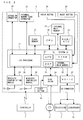
- FIG. 2 is a block diagram of the game apparatus body 5.
- the game system 1 will be described.
- the game system 1 is composed of a home television receiver (hereinafter referred to as a monitor) 2, which is exemplary display means, and the stationary game apparatus 3 connected to the monitor 2 via a connection cord.
- the monitor 2 includes loudspeakers 2a for outputting an audio signal outputted from the game apparatus body 5.
- the game apparatus 3 includes an optical disc 4 having a game program stored thereon, the game apparatus body 5 incorporating a computer for executing the game program stored on the optical disc 4 and for outputting and displaying a game screen on the monitor 2, and a controller 7 for providing the game apparatus body 5 with operational information necessary for operating a play character or the like displayed on the game screen.
- the game apparatus body 5 embeds therein a wireless controller module 19 (see FIG. 2 ).
- the wireless controller module 19 receives data wirelessly transmitted from the controller 7, and transmits the data from the game apparatus body 5 to the controller 7, thereby causing the controller 7 and the game apparatus body 5 to be connected to each other via wireless communication.
- the optical disc 4, which is an exemplary information storage medium exchangeably used to the game apparatus body 5, is detachably inserted to the game apparatus body 5.
- the game apparatus body 5 is equipped with a flash memory 17 (see FIG. 2 ) which functions as abackupmemory for fixedly storing data such as various data described later and save data saved during game software processing.
- a flash memory 17 which functions as abackupmemory for fixedly storing data such as various data described later and save data saved during game software processing.
- the game program or the like stored on the optical disc 4 is executed, and a result thereof is displayed on the monitor 2 as a game image.
- the game program or the like may be previously stored in the flash memory 17 and then executed. Further, on the game apparatus body 5, by using the save data stored in the flash memory 17, it is possible to reproduce a game state previously executed and to display the game image on the monitor 2.
- a player of the game apparatus body 5 views the game image displayed on the monitor 2, and enj oys a progress of the game while operating the controller 7.
- the display control program of the present invention is previously stored in an involatile storage apparatus (e.g., the f lash memory 17) provided in the game apparatus body 5.
- the display control program of the present invention is provided to the game apparatus body 5 via an external storage medium such as the optical disc 4.
- the display control program of the present invention is provided to the game apparatus body 5 via a wired or wireless communication line.
- the game apparatus body 5, on which the display control program is executed, uses broadcast listing data provided thereto through the wired or wireless communication line and causes a broadcast listing indicated by the broadcast listing data to be displayed on the monitor 2.
- the controller 7 wirelessly transmits transmission data such as operation information and the like by using a technique of Bluetooth (registered trademark) to the game apparatus body 5 having the wireless controller module 19 embedded therein.
- the controller 7 is operation means for mainly operating an object and the like displayed on a display screen of the monitor 2.
- the controller 7 has a housing of a size small enough to be held by one hand, and also has a plurality of operation buttons (including a cross key, a stick and the like) exposed on the surface of the housing.
- the controller 7 includes an imaging information calculation section 74 for picking up an image as viewed from the controller 7.
- two LED modules (hereinafter referred to as markers) 8L and 8R are located in the vicinity of the display screen of the monitor 2.
- the markers 8L and 8R each outputs infrared light, for example, forward from the monitor 2.
- the controller 7 is capable of receiving, by using communication section 75 provided therein, the transmission data wirelessly transmitted from the wireless controller module 19 of the game apparatus body 5, and generating a sound and vibration corresponding to the transmission data.
- FIG. 2 is a block diagram showing a configuration of the game apparatus body 5.
- the game apparatus body 5 includes a CPU (Central Processing Unit) 10, a system LSI (Large Scale Integration) 11, an external main memory 12, a ROM/RTC (Read Only Memory/Real Time Clock) 13, a disc drive 14, an AV-IC (Audio Video-Integrated Circuit) 15, the flash memory 17, and the like.
- CPU Central Processing Unit
- LSI Large Scale Integration
- ROM/RTC Read Only Memory/Real Time Clock
- disc drive 14 an AV-IC (Audio Video-Integrated Circuit) 15, the flash memory 17, and the like.
- AV-IC Audio Video-Integrated Circuit
- the CPU 10 executes the display control program stored in the flash memory 17 or the like, thereby performing the display control processing. That is, the CPU 10 functions as a display control processor.
- the CPU 10 also functions as a game processor, and executes a game process by executing the game program stored on the optical disc 4.
- the CPU 10 is connected to the system LSI 11. To the system LSI 11, not only the CPU 10, but also the external main memory 12, the ROM/RTC 13, the disc drive 14, and the AV-IC 15 are connected.
- the system LSI 11 performs processing such as control of data transmission among respective component parts connected thereto, generation of an image to be displayed, acquisition of data from an external apparatus, and the like. An internal configuration of the systemLSI 11 will be described later.
- the external main memory 12 which is of a volatile type, stores therein programs such as the game program read from the optical disc 4 and the display control program read from the flash memory 17, and various data.
- the external main memory 12 is used as a work area and a buffer space for the CPU 10.
- the ROM/RTC 13 includes a ROM (so-called a boot ROM) incorporating a program for starting up the game apparatus body 5, and a clock circuit (RTC) for counting time.
- the disc drive 14 reads program data, texture data and the like from the optical disc 4, and writes the read data into an internal main memory 35 described later or the external main memory 12.
- I/O input/output
- GPU Graphics Processor Unit
- DSP Digital Signal Processor
- VRAM Video RAM
- the GPU 32 functions as a part of drawing means, and generates an image in accordance with a graphics command (draw command) from the CPU 10.
- the VRAM 34 stores therein data (such as polygon data and texture data) necessary for the GPU 32 to execute the graphics command.
- the GPU 32 uses data stored in the VRAM 34 and generates the image data.
- the DSP33 functions as an audio processor, and generates audio data by using sound data and sound waveform (tone quality) data stored in the internal main memory 35 and the external main memory 12.
- the DSP 33 reads the above-described sound data, and outputs the read data to the loudspeakers 2a via the AV-IC 15 and the AV connector 16, the loudspeakers 2 being provided on the monitor 2.
- the DSP33 reads the above-described sound data and transmits the sound data to the controller 7 via the wireless controller module 19 and an antenna 23.
- the image data and the audio data generated as above described are read by the AV-IC 15.
- the AV-IC 15 outputs the read image data to the monitor 2 via the AV connector 16, and also outputs the read audio data to the loudspeakers 2a embedded in the monitor 2. Accordingly, the image is displayed on the monitor 2, and the sound is outputted from the loudspeakers 2a.
- the I/O processor 31 executes transmission of data among component parts connected thereto, and also executes download of data from an external apparatus.
- the I/O processor 31 is connected to the flash memory 17, the wireless communication module 18, the wireless controller module 19, an extension connector 20, and an external memory card connector 21.
- An antenna 22 is connected to the wireless communication module 18, and an antenna 23 is connected to the wireless controller module 19.
- the I/O processor 31 is connected to a network via the wireless communication module 18 and the antenna 22, and is capable of communicating with another game apparatus and various servers connected to the network.
- the I/O processor 31 accesses the flash memory 17 at regular intervals so as to detect data, if any, which is necessary to be transmitted to the network. If the data is detected, the detected data is transmitted to the network via the wireless communication module 18 and the antenna 22.
- the I/O processor 31 receives data transmitted from another game apparatus and data (such as electronic broadcast listing data) downloaded from a download server via the network, the antenna 22 and the wireless communication module 18, and stores the received data in the flash memory 17.
- the CPU 10 executes the game program, and read the data stored in the flash memory 17 so as to be used for executing the game program and the display control program.
- the flash memory 17 not only data transmitted between the game apparatus body 5 and another game apparatus or various servers, but also save data of a game (result data or midstream data of the game) played by using the game apparatus body 5 may be stored.
- the I/O processor 31 receives operation data and the like, which is transmitted from the controller 7 via the antenna 23 and the wireless controller module 19, and (temporarily) stores the operation data in the internal main memory 35 or in the buffer space of the external main memory 12.
- the internal main memory 35 may be used for storing therein the programs such as the game programs read from the optical disc 4 and from the flash memory 17, and various data, and may be used as the work area or the buffer space for the CPU 10.
- the extension connector 20 and the external memory card connector 21 are connected to the I/O processor 31.
- the extension connector 20 is an interface connector as typified by a USB and an SCSI, and is capable of performing communication with the network, instead of the wireless communication module 18, by connecting thereto a medium such as an external storage medium, a peripheral device such as another controller, or a wired communication connector.
- the external memory card connector 21 is a connector for connecting thereto the external storage medium such as a memory card.
- the I/O processor 31 accesses the external storage medium via the extension connector 20 or the external memory card connector 21, and then saves data or reads data.
- a power button 24 of the game apparatus body 5 for example, on the front main surface thereof
- a reset button 25 of the game process for example, an insertion slot in which the optical disc 4 is inserted
- an eject button 26 for causing the optical disc 4 to be ejected from the insertion slot of the game apparatus body 5, and the like.
- the power button 24 and the reset button 25 are connected to the system LSI 11.
- the system LSI 11 When the reset button 25 is pressed, the system LSI 11 reactivates the start-up program of the game apparatus body 5.
- the eject button 26 is connected to the disc drive 14. When the eject button 26 is pressed, the optical disc 4 is ejected from the disc drive 14.
- FIG. 3 is a perspective view of the controller 7 as viewed from a top rear side thereof.
- FIG. 4 is a perspective view of the controller 7 as viewed from a bottom front side thereof.
- the controller 7 includes a housing 71, which is formed by, for example, plastic molding, and a plurality of operation sections are provided on the housing.
- the housing has a substantially parallelepiped shape extending in a longitudinal direction from front to rear, and an overall size thereof is small enough to be held by one hand of an adult or even a child.
- a cross key 72a is provided at a front center portion of a top surface of the housing 71.
- the cross key 72a is a cross-shaped four direction push switch, and the operation portions thereof are respectively located on cross-shaped projecting portions arranged at intervals of 90 degrees such that the operation portions correspond to four directions (front, rear, right and left).
- a player selects one of the front, rear, right, and right directions by pressing one of the operation portions of the cross key 72a.
- the player can, for example, scroll and display a broadcast listing, indicate a direction in which a player character or the like appearing in a virtual game world is tomove, or select an instruction from a plurality of choices.
- the cross key 72a is an operation section for outputting an operation signal in accordance with the direction input operation performed by the player as above described, and such an operation may be provide in another form.
- the operation section may be provided such that four push switches are arranged in the cross directions and an operation signal is outputted by the player' s pressing one of the four push switches.
- a center switch may be provided at a crossing position of the above-described cross directions so as to provide an operation section composed of the four push switches and the center switch.
- the cross key 72a may be replaced with an operation section which includes an inclinable stick (so called a joystick) projecting from the top surface of the housing 71 and which outputs the operation signal in accordance with an inclining direction of the stick.
- the cross key 72a may be replaced with an operation section which includes a disc-shaped member horizontally slidable and which outputs an operation signal in accordance with an sliding direction of the disc-shaped member.
- the cross key 72a may be replaced with a touchpad.
- a plurality of operation buttons 72b, 72c, 72d, 72e, 72f and 72g are provided.
- the operation buttons 72b, 72c, 72d, 72e, 72f and 72g are each an operation section for outputting an operation signal assigned thereto when the player presses a head thereof.
- functions such as a No. 1 button, a No. 2 button, an A button and the like are assigned to the operation buttons 72b, 72c and 72d.
- functions such as a minus button, a home button, a plus button and the like are assigned to the operation buttons 72e, 72f and 72g.
- operation buttons 72a, 72b, 72c, 72d, 72e, 72f and 72g are assigned to these operation buttons 72a, 72b, 72c, 72d, 72e, 72f and 72g in accordance with the game program executed by the game apparatus body 5.
- a character size of a broadcast displayed in a broadcast listing may be changed.
- the operation button 72e (minus button) or the operation button 72g (plus button) is pressed, a time axis of the displayed broadcast listing may be changed.
- the operation buttons 72b, 72c and 72d are arranged in a line at the center in a front-rear direction on the top surface of the housing 71.
- the operation buttons 72e, 72f, and 72g are arranged in a line on the top surface of the housing 71 in a left-right direction between the operation buttons 72b and 72d.
- the operation button 72f has a top surface thereof buried in the top surface of the housing 71 so as not to be inadvertently pressed by the player.
- an operation button 72h is provided in front of the cross key 72a on the top surface of the housing 71.
- the operation button 72h is a power switch for turning on and off the power to the game apparatus body 5 by remote control.
- the operation button 72h also has a top surface thereof buried in the top surface of the housing 71, so as not to be inadvertently pressed by the player.
- a plurality of LEDs 702 is provided.
- a controller type (number) is assigned to the controller 7 such that the controller 7 is distinguishable from another controller 7.
- the LEDs 702 are used for, for example, informing the player about the controller type currently set for the controller. Specifically, a signal is transmitted, from the wireless controller module 19 to the controller 7, so as to light a LED corresponding to the above-described controller type among the plurality of LEDs 702.
- loudspeaker holes for emitting a sound from a loudspeaker are formed between the operation button 72b and the operation buttons 72e, 72f and 72g.
- a recessed portion is formed on a bottom surface of the housing 71.
- the recessed portion on the bottom surface of the housing 71 is formed in a position in which an index finger or middle finger of the player is located when the player holds the controller 7 with one hand and points a front portion thereof to the markers 8L and 8R.
- an operation button 72i is provided on a slope surface of the recessed portion.
- the operation button 72i is an operation section acting as, for example, a B button. For example, when the player points and moves the controller 7 while pressing the operation button 72i, the broadcast listing may be scroll-displayed.
- an image pickup element 743 constituting a part of an imaging information calculation section 74 is provided on a front surface of the housing 71.
- the imaging information calculation section 74 is a system which analyzes image data picked up by the controller 7, identifies an area having a high brightness point in the image, and detects a position of a gravity center, a size and the like of the area.
- the imaging information calculation section 74 has, for example, a maximum sampling period of about 200 frames/sec., and thus can trace and analyze even a relatively fast motion of the controller 7. A configuration of the imaging information calculation section 74 will be described later in detail.
- a connector 73 is provided on a rear surface of the housing 71.
- the connector 73 is, for example, an edge connector, and is used for coupling and connecting the controller with a connection cable.
- FIG. 5 is a perspective view of the controller 7 as viewed from a rear side, the controller 6 being in a state where an upper housing (a part of the housing 71) of the controller 7 is removed.
- FIG. 6 is a perspective view of the controller 7 as viewed from a front side, the controller 7 being in a state where a lower housing (a part of the housing 71) of the controller 7 is removed.
- FIG. 6 is also a perspective view as viewed from a reverse side of the substrate 700 shown in FIG. 5 .
- the substrate 700 is fixed inside the housing 71.
- the operation buttons 72a, 72b, 72c, 72d, 72e, 72f, 72g and 72h are connected to a microcomputer 751 or the like (see FIGs 6 and 7 ) by lines (not shown) formed on the substrate 700 or the like.
- the wireless module 753 (see FIG. 7 ) and the antenna 754 allow the controller 7 to act as a wireless controller.
- a quartz oscillator which is not shown, is provided in an inside of the housing 71, and generates a reference clock of the microcomputer 751 described later.
- the loudspeaker 706 and an amplifier 708 are provided on the top main surface of the substrate 700.
- the acceleration sensor 701 is provided at the left side of the operation button 72d on the substrate 700 (that is, at a peripheral portion, instead of a center portion, on the substrate 700). Accordingly, the acceleration sensor 701 can detect, in accordance with a rotation centering on the longitudinal direction of the controller 7, acceleration caused by a centrifugal force element as well as directional variation in gravitational acceleration. Therefore, based on a predetermined calculation, the game apparatus body 5 and the like can detect, from the detected acceleration data, the motion of the controller 7 highly sensitively.
- the controller 7 includes triaxial acceleration sensor 701.
- the triaxial acceleration sensor 701 detects linear acceleration in three directions, i.e., an up-down direction, a left-right direction and a front-rear direction. Data indicative of acceleration detected by the acceleration sensor 701 along the respective directions is outputted to the communication section 75.
- the imaging information calculation section 74 includes an infrared filter 741, a lens 742, the image pick up element 743, and an image processing circuit 744, which are located in this order from the front side of the controller 7, and provided on the bottom main surface of the substrate 700.
- the connector 73 is attached.
- a sound IC 707 and the microcomputer 751 are provided on the bottom main surface of the substrate 700.
- the sound IC 707 is connected to the microcomputer 751 and the amplifier 708 by lines formed on the substrate 700 or the like, and outputs an audio signal to the loudspeaker 706 via the amplifier 708 in accordance with the audio data transmitted from the game apparatus body 5.
- a vibrator 704 is attached on the bottom main surface of the substrate 700.
- the vibrator 704 may be, for example, a vibration motor or a solenoid.
- the vibrator 704 is connected to the microcomputer 751 via the lines formed on the substrate 700 or the like, and an operation thereof is turned on/off in accordance with vibration data transmitted from the game apparatus body 5.
- the controller 7 is vibrated when the vibrator 704 is turned on, and vibration is conveyed to the player holding the controller.
- the vibrator 704 is located at a relatively front side of the housing 71, and thus the housing 71 vibrates to a large extent while the player is holding the housing 71, whereby the player feels vibration sensitively.
- FIG. 7 is a block diagram showing a configuration of the controller 7.
- the controller 7 includes thereinside a communication section 75, in addition to the operation sections 72, the imaging information calculation section 74, the acceleration sensor 701, the vibrator 704, the loudspeaker 706, the sound IC 707, and the amplifier 708 which are described as above.
- the imaging information calculation section 74 includes the infrared filter 741, the lens 742, the image pickup element 743 and the image processing circuit 744.
- the infrared filter 741 allows only an infrared radiation to pass therethrough, the infrared radiation being included in the light which is incident on the front side of the controller 7.
- the lens 742 converges the infrared radiation which has passed through the infrared filter 741, and outputs the infrared radiation to the image pickup element 743.
- the image pickup element 743 is a solid-state image pickup element such as a CMOS sensor or a CCD, and picks up an images of the infrared radiation converged by the lens 742.
- the image pickup element 743 picks up the image of only the infrared radiation having passed through the infrared filter 741, and generates image data.
- the image data generated by the image pickup element 743 is processed by the image processing circuit 744.
- the image processing circuit 744 processes the image data obtained from the image pickup element 743 and detects a high brightness point thereof, and outputs, to the communication section 75, a process result data indicative of a result of the detection of a position of the high brightness point.
- the imaging information calculation section 74 is fixed on the housing 71 of the controller 7, and an imaging direction of the housing 71 can be changed by changing the orientation of the housing 71.
- the communication section 75 includes the microcomputer 751, a memory 752, the wireless module 753 and the antenna 754.
- the microcomputer 751 controls the wireless module 753 for wirelessly transmitting the transmission data while using the memory 752 as a storage area at the time of processing. Further, the microcomputer 751 controls operations of the sound IC 707 and the vibrator 704 in accordance with the data received by the wireless module 753 from the game apparatus body 5 via the antenna 754.
- the sound IC 707 processes the sound data and the like transmitted from the game apparatus body 5 via the communication section 75. Further, the microcomputer 751 actuates the vibrator 704 in accordance with the vibration data (e.g., signal for turning the vibrator 704 ON or OFF) and the like which are transmitted from the game apparatus body 5 via the communication section 75.
- Data from the controller 7 such as an operation signal (key data) from the operation section 72, acceleration signals (acceleration data) in three axes directions from the acceleration sensor 701, and the process result data from the imaging information calculation section 74 are outputted to the microcomputer 751.
- the microcomputer 751 temporarily stores the inputted data (the key data, the acceleration data, and the process result data) in the memory 752 as the transmission data to be transmitted to the wireless controller module 19.
- the wireless transmission from the communication section 75 to the wireless controller module 19 is performed at predetermined time intervals. Since the game process is generally performed at an interval of 1/60 sec., the wireless transmission needs to be performed at an interval of a shorter time period. Specifically, the game process is performed at an interval of 16.
- the microcomputer 751 outputs the transmission data stored in the memory 752 to the wireless module 753 as a series of pieces of operation information.
- the wireless module 753 emits, from the antenna 754, a radio signal indicative of the operation information by using a carrier wave having a predetermined frequency.
- the radio signal is received by the wireless controller module 19 of the game apparatus body 5, and the radio signal is then demodulated or decoded in the game apparatus body 5, whereby the series of pieces of operation information (the key data, the acceleration data and the process result data) are obtained.
- the CPU 10 of the game apparatus body 5 performs the game process in accordance with the obtained operation information and the game program.
- the communication section 75 may have a function of receiving transmission data which is wirelessly transmitted from other devices.
- a user In order to play a game on the game system 1 by using the controller 7, a user holds the controller 7 by one hand (e.g., the right hand). The user then holds the controller 7 such that the front surface (an entrance side on which light picked up by the imaging information calculation section 74 is incident) of the controller 7 faces the monitor 2.
- the controller 7 On the other hand, in the proximity of the display screen of the monitor 2, two markers 8L and 8R are arranged (see FIG. 1 ).
- the markers 8L and 8R each outputs the infrared radiation forward from the monitor 2, and constitutes an imaging target of the imaging information calculation section 74.
- the markers 8L and 8R each has a viewing angle of ⁇ 1.
- the image pickup element 743 has a viewing angle of ⁇ 2.
- the viewing angle ⁇ 1 of each of the markers 8L and 8R is 34° (a half value angle), and the viewing angle ⁇ 2 of the image pickup element 743 is 41°. If the markers 8L and 8R are located within the viewing angle ⁇ 2 of the image pickup element 743, and the image pickup element 743 is located within the viewing angle ⁇ 1 of the marker 8L and within the viewing angle ⁇ 1 of the marker 8R, the game apparatus body 5 calculates a position pointed by the controller 7 by using position data relating to the high brightness point generated by the markers 8L and 8R.
- the infrared radiations outputted from each of the markers 8L and 8R are incident on the imaging information calculation section 74.
- the image pickup element 743 picks up images of the incident infrared radiations via the infrared filter 741 and the lens 742, and the image processing circuit 744 processes the picked up images.
- the imaging information calculation section 74 components of the infrared radiation outputted from each of the markers 8L and 8R are detected, whereby positional information (positions of target images) and the like of the markers 8L and 8R in the picked up image are obtained.
- the image processing circuit 744 analyzes the image data picked up by the image pickup element 743, eliminates, from area information of the picked up image, images which are not generated by the infrared radiations outputted from the markers 8L and 8R, and then determines the high brightness points as the positions of the markers 8L and 8R.
- the imaging information calculation section 74 obtains positional information such as barycentric positions of the determined high rightness points, and outputs the positional information as the process result data.
- the positional information, which is the process result data may be outputted as coordinate values whose origin point is set to a predetermined reference point on the picked up image (e.g. , the center or the left top corner of the picked up image).
- a brightness point position at a predetermined timing may be set as a reference point position, and a difference between the reference point position and a current brightness point position may be outputted as a vector. That is, in the case where a predetermined reference point is set on the image picked up by the image pickup element 743, the positional information of the target images is used as parameters representing differences between the positions of the target images and the reference point position.
- the positional information is transmitted to the game apparatus body 5, whereby, based on the difference between the reference point position and the positional information, the game apparatus body 5 is capable of obtaining variations in signals which corresponds to a movement, an attitude, a position and the like of the imaging information calculation section 74, i.e., the controller 7 with respect to the markers 8L and 8R.
- the imaging information calculation section 74 i.e., the controller 7 with respect to the markers 8L and 8R.
- the controller 7 when the controller 7 is moved, the high brightness point position on an image transmitted from the communication section 75 changes. Therefore, by inputting a direction or a coordinate point in accordance with a change in the high brightness point position, a position pointed by the controller 7 is considered as an operation input, and a direction or a coordinate point can be inputted in accordance with a moving direction of the controller 7.
- the imaging information calculation section 74 at least obtains the coordinate points of the barycenteric positions of the respective target images of the markers 8L and 8R on the picked up images, and outputs the obtained coordinate points as the process result data.
- the imaging information calculation section 74 of the controller 7 picks up the markers (the infrared radiations from the markers 8L and 8R in the embodiment) which is located fixedly, whereby data outputted from the controller 7 is processed in the game process on the game apparatus body 5, and an operation can be performed in accordance with the movement, the attitude, the position and the like of the controller 7. Further, it becomes possible to perform an intuitive operation input which is different from an input by pressing the operation button and the operation key. Since the above-described markers are located in the proximity of the display screen of the monitor 2, a position of the controller 7 with respect to the markers can be easily converted to the movement, the attitude, position and the like of the controller 7 with respect to the display screen of the monitor 2. That is, the process result data based on the movement, the attitude, the position and the like of the controller 7 is used as the operation input directly reflected on the display screen of the monitor 2 (e.g., inputting a position pointed by the controller 7).
- the markers the infrared radiations from the markers 8L and 8R
- FIG. 9 is an exemplary screen illustrating a first example of a broadcast listing displayed on the monitor 2.
- FIG. 10 is another exemplary screen illustrating a second example of the broadcast listing displayed on the monitor 2.
- FIG. 11 is another exemplary screen illustrating a third example of the broadcast listing displayed on the monitor 2.
- the broadcast listing is displayed on the monitor 2 in a matrix form, where a horizontal axis represents a time axis, and a vertical axis represents a broadcast station axis.
- broadcast cells corresponding to time frames, in which television stations broadcast respective broadcasts, are set respectively, and a broadcast title is described in characters in each of the broadcast cells.
- the operation button 72b No.1 button
- the operation button 72c No.2 button
- the character size of the broadcast title is changed.
- the operation button 72e minus button
- the operation button 72g plus button
- the length of the time axis of a displayed broadcast listing is expanded or shortened.
- the user moves the position pointed with the controller 7 while pressing the operation button 72i, or when the user presses the operation button 72a (cross key)
- the broadcast listing is scroll-displayed.
- a broadcast listing is displayed in which the time axis shows three hourly time frames, respectively staring from 19, 20 and 21 hours, and the broadcast station axis shows five television stations A, B, C, D and E.
- the user sets the character size displayed on the screen to "small". Accordingly, most of the broadcast titles displayed in the broadcast cells of the respective television stations are each displayed in a "small" character size from the first character of each of the broadcast titles. For example, in a broadcast cell of the television A broadcasted during an hourly time frame starting from 19 hours, a broadcast title "ABCDEFGHIJKLMN" is described in the "small" character size.
- the user can select the character size from three types of character sizes, i.e., "large”, “medium”, and “small”. Although the user cannot select a "extra small” character size, which is smaller than the "small” character size, the "extra small” is set as a character size to be displayed.
- a broadcast title "ABC” is described in the broadcast cell C2 in the "extra small” character size, which is smaller than the "small” character size. This is because, as a rule, at least three characters of a broadcast title to be displayed on the monitor 2 need to be described in the broadcast cell. Specifically, when the "small” character size is used, the broadcast title cannot be displayed at least in the three characters in the broadcast cell C2. When the "extra small” character size is used, it is possible to vertically display the broadcast title in the three characters. In this case, even if the user selects the "small” character size, the broadcast title is described in the "extra small” character size in the broadcast cell C2.
- the broadcast listing is displayed in which the time axis shows three hourly time frames, respectively staring from 19, 20 and 21 o'clocks, and the broadcast station axis shows five television stations A, B, C, D and E.
- the user sets the character size displayed on the screen to "large". Accordingly, most of the broadcast titles displayed in the broadcast cells of the respective television stations are each displayed in a large character size from the first character of each of the broadcast titles.
- broadcast cells C1 to C3 shown in each of FIGs 9 and 10 will be paid attention.
- the user selects the "small” character size
- four characters of a broadcast title "abcd” are displayed in the "small” character size in the broadcast cell C1 ( FIG. 9 ).
- the user selects the "large” character size
- four characters of the broadcast title "abcd” are displayed in the "small” character size in the broadcast cell C1 ( FIG. 10 ).
- the broadcast cell C1 is of a size in which three characters cannot be described in the "large” character size or in the "medium” character size, and instead, is of a size in which four characters can be described in the "small” character size.
- the broadcast title is described in the "small” character size in the broadcast cell C1.
- the broadcast title "ABC” is described in "extra small” character size in the broadcast cell C2 ( FIG. 10 ).
- no broadcast title is described in the broadcast cell C3 ( FIG. 10 ).
- the broadcast listing is displayed while a length of each of the hourly time frames along the time axis is shortened compared with that shown in FIGs. 9 and 10 . That is, the number of hourly time frames of the broadcast listing is increased. Specifically, the broadcast listing is displayed in which the time axis shows four hourly time frames respectively starting from 19, 20, 21 and 22 o'clocks and the broadcast station axis shows five television station A, B, C, D and E. As to the display mode shown in FIG. 11 , the user sets the character size to be displayed to "large", as with the case shown in FIG. 10 .
- the broadcast cell of each of the television station is shortened horizontally, and most characters of the broadcast titles described in the respective broadcast cells are each described in the "large" character size from the first character of each of the broadcast titles.
- a broadcast title "ABCD” which is the first four characters of the broadcast title "ABCDEFGHIJKLMN”
- ABSCD the first four characters of the broadcast title
- a time axis scale selected by the user, only drawable number of characters of the broadcast title are displayed in the broadcast cell from the first character of the broadcast title.
- broadcast cells C1 to C4 shown in each of FIGs. 9 and 10 will be focused.
- four characters of the broadcast title "abcd” are described in the "small” character size in the broadcast cell C1.
- FIG. 11 after the user has shortened the hourly time frames along the time axis, three characters of the broadcast title "abc” are described in the "extra small” character size in the broadcast cell C1. This is also because, as the rule, at least three characters of a broadcast title to be displayed on the monitor 2 need to be described in the broadcast cell.
- the broadcast cell C1 becomes small enough that said at least three characters of the broadcast title cannot be described in any of the "small", “medium” and “large” character sizes. Instead, when the "extra small” character size is used, three characters can be described vertically. In this case, regardless of the character size selected by the user, the broadcast title is described in the "extra small” character size in the broadcast cell C1. As shown in FIG. 11 , after the user has shortened the hourly time frames along the time axis, no broadcast title is described in either of the broadcast cells C2 or C3.
- the broadcast cells C2 and C3 become small enough that said at least three characters of the broadcast title cannot be described even if the "extra small” character size is used. In this case, regardless of the character size selected by the user, no broadcast title is described in none of the broadcast cells C2 and C3. Further, as shown in FIGs. 9 and 10 , before the hourly time frames along the time axis are shortened, a broadcast title "12345” composed of five characters is described in the "small” character size, and a broadcast title "1234" having four characters is described in the "large” character size in respective broadcast cells C4. On the other hand, as shown in FIG.
- the broadcast title "1234" having four characters are described in the "small” character size in the broadcast cell C4.
- the broadcast cell C4 becomes of a size in which three characters cannot be described in the case of the "large” or “medium” character size, whereas four characters can be described in the case of the "small” character size. In this case, even if the user selects the "large” or “medium” character size, the broadcast title is described in the "small” character size in the broadcast cell C4.
- FIG. 12 is a diagram showing an example of the major data stored in the external main memory 12 and/or internal main memory 35 (hereinafter collectively referred to as a main memory) of the game apparatus body 5.
- FIG. 13 is a diagram showing, in detail, an exemplary content of broadcast cell data Db2 shown in FIG. 12 .
- operation information Da As shown in FIG. 12 , operation information Da, broadcast listing data Db and the like are stored in the main memory.
- main memory in addition to the data included in the information shown in FIG. 12 , data necessary for information processing and display control processing is stored as appropriate.
- the operation information Da stores therein the series of pieces of operation information (the key data, the acceleration data and the process result data) transmitted from the controller 7 as the transmission data, and the operation data is updated to latest operation information.
- the operation information Da includes first coordinate point data Dal and second coordinate point data Da2 which correspond to the positional information of the process result data.
- the first coordinate point data Dal represents data indicative of a position of the image of either of the markers 8L and 8R with respect to the image picked up by the image pickup element 743 (a position within the picked up image).
- the second coordinate point data Da2 represents data indicative of a position of the image (a position within the picked up image) of the other marker.
- the positions of the images of the markers in the picked up image is represented by an xy coordinate system in the picked up image.
- the operation information Da includes key data Da3 and the like obtained from the operation section 72, in addition to the coordinate point data (the first coordinate point data Dal and the second coordinate point data Da2), which is exemplary process result data obtained from the picked up image.
- the wireless controller module 19 provided in the game apparatus body 5 receives the series of pieces of operation information transmitted from the controller 7 at a predetermined interval of 5ms, for example, and stores the operation information in a buffer (not shown) provided in the wireless controller module 19.
- the latest operation information stored in the buffer is read at an interval of one frame (e.g., 1/60 sec.), which is an interval of the game process, and the operation information Da stored in the main memory is updated.
- the broadcast listing data Db stores therein information for displaying the broadcast listing on the monitor 2.
- the broadcast listing data Db includes display area coordinate point data Db1, broadcast cell data Db2, scroll amount data Db3, time axis setting data Db4, user setting character size data Db5, image data Db6, and the like.
- the display area coordinate point data Db1 stores therein coordinate point data indicative of a position of a display area, in the broadcast listing, to be displayed on the monitor 2 (e. g. , positions of a left top corner and a right bottom corner of the display area).
- the broadcast cell data Db2 stores therein data indicative of information on respective broadcast cells included in the broadcast listing, which will be described later in detail.
- the scroll amount data Db3 stores therein data indicative of an amount and a direction of scrolling the broadcast listing, the amount and direction being set by the user' s operation input.
- the time axis setting data Db4 stores therein data indicative of a time axis scale of the broadcast listing, the time axis scale being set by the user's operation input.
- the user setting character size data Db5 stores therein data indicative of the character size of the broadcast listing, the character size being set by the user' s operation input.
- the image data Db6 stores therein data indicative of various images so as to display the broadcast listing on the monitor 2.
- information included in the broadcast cell data Db2 is updated as appropriate by using electronic broadcast listing data which is obtained through communication with various servers connected to the network via the wireless communication module 18 and the antenna 22.
- the broadcast cell data Db2 is set for each of the broadcast cells arranged in the broadcast listing.
- the broadcast cell data Db2 includes a broadcast cell number Db2a, broadcast title character string data Db2b, number-of-broadcast-title-characters data Db2c, television station data Db2d, broadcast cell coordinate point data Db2e, drawing area width data Db2f, drawing area height data Db2g, drawing character size data Db2h, drawable-number-of-lines data Db2i, drawable-number-of-characters data Db2j and the like with respect to each of the broadcast cells.
- the broadcast cell number Db2a stores therein sequential numbers which are each set for each of the broadcast cells (e. g. , broadcast cell number "1" as shown in FIG. 13 ).
- the broadcast title character string data Db2b stores therein character string data indicative of the broadcast title (e.g., broadcast title character string "ABCDEFGH” as shown in FIG. 13 ) to be described in each of the broadcast cells.
- the number-of-broadcast-title-characters data Db2c stores therein the number of characters of the broadcast title in each of the broadcast cells (e.g., the number of the broadcast characters "8" as shown in FIG. 13 ).
- the television station data Db2d stores therein data indicative of the television station allocated to each of the broadcast cells (e. g.
- the broadcast cell coordinate point data Db2e stores therein data indicative of a position of each of the broadcast cells in the broadcast listing (e.g. , a left top corner coordinate point (xsa, ysa) and a right bottom corner coordinate point (xsb, ysb) shown in FIG. 13 ).
- the drawing area width data Db2f stores therein data indicative of a drawing area width of each of the broadcast cells, the width in which the broadcast title is drawable (e.g. , a drawing area width "dw" shown in FIG. 13 ).
- the drawing area height data Db2g stores therein a drawing area height of each of the broadcast cells, the height in which the broadcast title is drawable (e.g., a drawing area height "dh” shown in FIG. 13 ).
- the drawing character size data Db2h stores therein data indicative of the size of the characters of the broadcast title to be described in each of the broadcast cells (e.g., the "medium” character size shown in FIG. 13 ).
- the drawable-number-of-lines data Db2i stores therein data indicative of the number of lines in each of the broadcast cells, the lines on which the broadcast title is drawable (e.g., the drawable number of lines "2" shown in FIG. 13 ).
- the drawable-number-of-characters data Db2j stores therein data indicative of the number of characters of the broadcast title drawable in each of the broadcast cell (e.g., the drawable number of characters "4" shown in FIG. 13 ).
- FIG. 14 is a flowchart showing a flow of the display control processing performed on the game apparatus body 5.
- FIG. 15 is a sub-routine showing, in detail, an operation of the drawing area width calculation processing in step 56 shown in FIG. 14 .
- FIG. 16 is a sub-routine showing, in detail, an operation of broadcast listing display updating processing in step 63 shown in FIG. 14 .
- FIG. 17 is a sub-routine showing, in detail, an operation of the drawable-number-of-characters calculation processing in step 98 shown in FIG. 16 .
- FIG. 18 is a diagram illustrating an exemplary setting of the display area of the broadcast listing.
- FIG. 15 is a sub-routine showing, in detail, an operation of the drawing area width calculation processing in step 56 shown in FIG. 14 .
- FIG. 16 is a sub-routine showing, in detail, an operation of broadcast listing display updating processing in step 63 shown in FIG. 14 .
- FIG. 17 is a sub-routine showing, in detail,
- FIG. 19 is a diagram illustrating exemplary settings of the drawing area width dw and the drawing area height dh set for each of the broadcast cells.
- FIG. 20 is a diagram illustrating exemplary settings of the drawing area width dw and the drawing area height dh which are set in the case where a portion of the broadcast cell stays within the display area.
- processing of displaying, on the monitor 2, characters in the broadcast cell, among the display control processing will be mainly described. Description of other processing not directly relating to the present invention will be omitted.
- each step executed by the CPU 10 is abbreviated as "S".
- the CPU 10 of the game apparatus body 5 executes the start-up program stored in the ROM/RTC 13, whereby respective component units such as the main memory are initialized.
- the display control program stored on the optical disc 4 or another storage medium is read into the main memory, and the CPU 10 causes execution of the display control program to be ready.
- Theflowchart shown in FIG. 14 indicates the display control processing performed after completion of the above-described processing.
- the CPU 10 performs an initial setting (step 51) and proceeds to the subsequent step.
- various pieces of information described in the broadcast cell data Db2 is updated to the latest information as appropriate by using the electronic broadcast listing data obtained through communication with various servers connected to the network via the wireless communication module 18 and the antenna 22, the initial setting of the broadcast listing is performed.
- respective parameters for displaying the broadcast listing are initialized.
- the CPU 10 sets parameters indicated by respective pieces of data stored in the main memory to default values, respectively.
- the CPU 10 performs display processing of the broadcast listing (step 52), and proceeds to the subsequent step. Specifically, the CPU 10 generates the broadcast listing in accordance with a state of the default setting set in step 51, and displays the generated broadcast listing on the monitor 2.
- the CPU 10 obtains the operation information received from the controller 7 (step 53), and then proceeds to the subsequent step.
- the CPU 10 then updates the operation information Da by using the obtained latest operation information.
- the operation information obtained in step 53 includes key data indicative of how the operation section 72 of the controller 7 is operated, in addition to the process result data indicative of the positions of the markers 8L and 8R on the picked up image.
- the communication section 75 transmits the operation information to the game apparatus body 5 at a predetermined time interval (e.g., at an interval of 5ms).
- the CPU 10 uses the transmitted latest operation information on a frame-by-frame basis, and updates the first coordinate point data Da1, the second coordinate point data Da2, and the key data Da3.
- the CPU 10 determines whether or not the user performs a scrolling operation of the broadcast listing (step 54), whether or not the user performs an operation to change the time axis of the broadcast listing (step 57), and whether or not the user performs an operation to change the character size of the broadcast listing (step 60). Specifically, the CPU 10 refers to the first coordinate point data Da1, the second coordinate point data Da2, and the key data Da3 included in the operation information Da, and determines a content of an operation performed by the user. The CPU 10 proceeds to subsequent step 55 when the user performs the scrolling operation of the broadcast listing (YES in step 54). Further, when the user performs the operation to change the time axis of the broadcast listing (YES in step 57), the CPU 10 proceeds to subsequent step 58.
- step 60 when the user performs the operation to change the character size of the broadcast listing (YES in step 60), the CPU 10 proceeds to subsequent step 61.
- the CPU 10 proceeds to subsequent step 62.
- step 55 the CPU 10 updates the coordinate point of the display area in accordance with the scroll amount corresponding to the user' s operation, and then proceeds to subsequent step 56. Specifically, the CPU 10 calculates the amount and the direction of scrolling the broadcast listing in accordance with a position pointed by the controller 7 and a pressing direction of the operation button 72a, and then updates the scroll amount data Db3. The CPU 10 calculates the coordinate points indicative of the left top corner and the right bottom corner of the display area, in accordance with the calculated amount and direction of scrolling, and updates the display area coordinate points data Db1.
- an exemplary calculation of the position pointed by the controller 7 and an exemplary setting of the display area will be described.
- the CPU 10 calculates a direction from the position indicated by the first coordinate point data Da1 to the position indicated by the second coordinate point data Da2, and a middle point therebetween.
- the middle point represents said one image.
- a positional relation among the markers 8L and 8R, the display screen of the monitor 2, and the controller 7 will be considered.
- a case will be considered where two markers 8L and 8R are located on the top surface of the monitor 2 (see FIG. 1 ), and the user points the controller 7 to a central part of the display screen of the monitor 2 while orientating the top surface of the controller 7 upward (that is, in a state where the central part of the display screen is located at a central part of the image picked up by the imaging information calculation section 74).
- the middle point of the target images does not correspond to the central part of the picked up image.
- the target images are located at positions above the central part of the picked image.
- a reference position is set such that the controller 7 points to the central part of the display screen when the target images are located at such positions.
- the positions of the target images on the picked up image also moves (to a direction opposite to the moving direction of the controller 7). Therefore, processing is performed so as to move the pointed position on the display screen in accordance with the movement of the positions of the target images on the picked up image, whereby it is possible to calculate a position on the display screen pointed to by the controller 7.
- the user may previously points to a predetermined position on the display screen so as to correlate the positions of the target images at that time point with the predetermined position and to store the correlation.
- the reference position may be set previously.
- the pointed position on the display screen is calculated based on linear transformation which uses a function for calculating, from the middle point, a coordinate point on the display screen of the monitor 2.
- the function converts a value of the coordinate point of the middle point calculated based on a picked up image into a position pointed to by the controller 7 on the display screen when the image is picked up by the controller 7.
- the pointed position on the display screen can be calculated based on the coordinate point of the middle point.
- the coordinate point of the middle point is corrected by using the direction stored in the direction data Db1
- the pointed position on the display screen is calculated by using the corrected middle point.
- the CPU 10 further converts the calculated pointed to position on the display screen into a position on the broadcast listing corresponding thereto.
- the position of the broadcast listing corresponding to the pointed position is perspectively projected to a position of the broadcast listing displayed on the display screen of the monitor 2.
- a position allocated based on the coordinate system fixed for the broadcast listing is set as a position of the display area.
- the broadcast listing is set such that the vertical axis represents a broadcast station axis and the horizontal axis represents the time axis.
- a coordinate system (hereinafter referred to as a broadcast listing coordinate point), in which a position at the left top corner of the broadcast listing represents a coordinate point (x0, y0), and a position at the right bottom corner of the broadcast listing represents a coordinate point (xmax, ymax), is set for the broadcast listing.
- the display area is allocated at a portion in the broadcast listing.
- a position at the left top corner (coordinate point (xa, ya)) and a position at the right bottom corner (coordinate point (xb, yb)) of the display area is set on the broadcast listing coordinate system, whereby a location and a size of the display area are determined.
- the position at the left top corner (coordinate point (xa, ya)) and the position at the right bottom corner (coordinate point (xb, yb)) of the display area are determined on the broadcast listing coordinate system, whereby the coordinate points of the display area is updated.
- the CPU 10 updates the drawing area width in accordance with the time axis changed in response to the user's operation (step 58).
- the CPU 10 then updates coordinate points of respective broadcast cells in accordance with the time axis changed in response to the user's operation (step 59), and proceeds to subsequent step 56.
- the CPU 10 changes the drawing area width dw and a position (the left top corner coordinate point (xsa, ysa) and the right bottom corner coordinate point (xsb, ysb)) of each of the broadcast cells in accordance with the hourly time frames along the time axis having been changed by the user, thereby updating the drawing area width data Db2f and the broadcast cell coordinate point data Db2e.
- a rectangular drawing area is set within the broadcast cell.
- a size of the drawing area is defined by the drawing area width dw and the drawing area size dh.
- a position at the left top corner (coordinate point (xsa, ysa)) and a position at the right bottom corner (coordinate point (xsb, ysb)) of the drawing area is determined based on the broadcast listing coordinate system.
- the drawing area width dw of each of the broadcast cells is changed in accordance with the changed hourly time frames along the time axis, whereby the drawing area width data Db2f of each the broadcast cells is updated.
- each of the broadcast cells (the left top corner coordinate point (xsa, ysa), the right bottom coordinate point (xsb, ysb)) is changed in accordance with the changed hourly time frames along the time axis, whereby the broadcast cell coordinate point data Db2e of each of the broadcasts cells is updated.
- the position of each of the broadcast cells may be changed by expanding or shortening each of the broadcast cells horizontally centering on a predetermined position (e.g., a central portion or a left edge) of the display area and by specifying the position of each of the broadcast cells in accordance with the broadcast listing coordinate system.
- each of the broadcast cells is expanded or shortened horizontally centering on a position pointed by the controller 7 on the broadcast listing, whereby the position of the position of each of the broadcast cells may be specified in accordance with the broadcast listing coordinate system.
- the CPU 10 sets a user setting character size in accordance with the user's operation (step 61), and proceeds to subsequence step 63. Specifically, the CPU 10 updates the user setting character size data Db5 in accordance with the character size changed by the user.
- the CPU 10 performs another processing in accordance with the user's operation (step 62), and proceeds to subsequent step 64.
- step 56 After processing in steps 55 and 59, the CPU 10 performs drawing area calculation processing (step 56), and proceeds to subsequent step 63. With reference to FIG. 15 , the drawing area calculation processing will be described.
- the CPU 10 sets a variable N, which is indicative of a broadcast cell number to be processed, to 1 (step 81), and proceeds to the subsequent step.
- the CPU 10 compares the coordinate points of the broadcast cell having the broadcast cell number N with the display area coordinate points (step 82), and determines whether or not the broadcast cell stays within the display area (step 83) and also determines whether or not any portion of the broadcast cell falls outside the display area (step 84).
- the CPU 10 refers to the broadcast cell coordinate point data Db2e and the display area coordinate point data Db1 of the broadcast cell having the broadcast cell number N, and obtains the left top corner coordinate point (xsa, ysa) and the right bottom corner coordinate point (xsb, ysb) of the broadcast cell having the broadcast cell number N, and the left top corner coordinate point (xa, ya) and the right bottom corner coordinate point (xb, yb) of the display area.
- the coordinate points a positional relation between the broadcast cell having the broadcast cell number N and the display area is analyzed.
- step 83, and Yes in step 84 the CPU 10 proceeds to subsequent step 85.
- the CPU 10 proceeds to subsequent step 86.
- the CPU 10 proceeds to subsequent step 88.
- step 85 the CPU 10 calculates the drawing area width dw of the broadcast cell having the broadcast cell number N, the drawing area width dw staying within the display area, and proceeds to subsequent step 87. For example, as shown in FIG. 20 , when the left portion of the broadcast cell falls outside the display area, a width between a left edge of the display area and the right edge of the broadcast cell in the drawing area is calculated as the drawing area width dw.
- step 86 the CPU 10 sets the drawing area width dw of the broadcast cell having the broadcast cell number N by using the drawing area width dw corresponding to the currently set time axis, and then proceeds to subsequent step 87.
- the CPU 10 sets the drawing area width dw of the broadcast cell having the broadcast cell number N by using a default value set in step 51, or by using a value set in step 58 after the change in the time axis.
- step 86 when a situation where a portion of the drawing area in the broadcast cell having the broadcast cell number N is displayed outside the display area has been changed to a situation where the whole portion of the drawing area is located within the display area, the drawing area width dw needs to be changed.
- the drawing area width dw is fixed.
- the processing in step 86 may be omitted. In this case, the processing in step 86 is performed only when the situation where the portion of the drawing area in the broadcast cell having the broadcast cell number N is displayed outside the display area is changed to the situation where the whole of the drawing area is located within the display area.
- step 87 the CPU 10 updates the drawing area width data Db2f of the broadcast cell having the broadcast cell number N by using the drawing area width dw calculated in step 85, or by using the drawing area width dw set in step 86, and proceeds to subsequent step 88.
- step 63 the broadcast listing display updating processing
- the CPU 10 selects any one of television stations (see FIG. 18 ) displayed in a line respectively along the time axis of the broadcast listing (step 91).
- the CPU 10 determines whether or not a top edge of a display range of the selected television station is lower than the display area (step 92), and also determines whether or not a bottom edge of the display range of the selected television station is higher than the display area (step 93).
- the CPU 10 proceeds to subsequent step 94.
- step 92 or step 93 the CPU 10 proceeds to subsequent step 106.
- the whole of the display range of the selection television station falls outside the display area (Yes in step 92 or step 93)
- the CPU 10 proceeds to subsequent step 106.
- television stations B, C, D, E and F shown in FIG. 18 at least a portion of the display range of each of the television stations stays within the display area.
- television stations A and G the whole of the display range of each of the television stations falls outside the display area.
- step 94 the CPU 10 selects any one of the broadcast cells included in a television station currently selected.
- the CPU 10 determines whether or not a right edge of a drawing range of the selected broadcast cell is located to the left of the display area (step 95), and also determines whether or not a left edge of the drawing range of the selected broadcast cell is located to the right of the display area (step 96).
- the CPU 10 proceeds to subsequent step 97.
- the whole drawing range of the selected broadcast cell falls outside the display area (Yes in step 95 or 96)
- the CPU 10 proceeds to subsequent step 105. For example, when the television station C shown in FIG. 18 is selected, at least portions of broadcasts C1, C2, C3 and C4, respectively, stay within the display area.
- the whole drawing area of the broadcast cell of the broadcast C5 falls outside the display area.
- step 97 the CPU 10 changes the drawing character size of the broadcast cell currently selected by using the character size set by the user, and proceeds to the subsequent step. Specifically, the CPU 10 refers to the user setting character size data Db5 so as to obtain the user setting character size, and updates the drawing character size data Db2h of the broadcast cell currently selected by using the user setting character size.
- the CPU 10 then performs the drawable-number-of-characters calculation processing (step 98), and proceeds to the subsequent step.
- step 98 the drawable-number-of-characters calculation processing
- FIG. 17 an operation of the drawable-number-of-characters calculation processing will be described in detail.
- the CPU 10 sets the current number of characters to 0 (step 111), and also sets the drawable number of characters to 0 (step 112).
- the CPU 10 calculates the number of character lines drawable in the drawing area of the currently selected broadcast cell (step 113).
- the CPU 10 sets a current number of lines to 1 (step 114), and proceeds to the subsequent step.
- the CPU 10 refers to the drawing area height data Db2g of the currently selected broadcast cell, and obtains the drawing area height dh.
- the CPU 10 refers to the drawing character size data Db2h of the currently selected broadcast cell, and obtains the drawing character size.
- the CPU 10 calculates the drawable number of character lines by dividing the obtained drawing area height dh by a line-height previously set to the obtained drawing character size, thereby updating the drawable-number-of-lines data Db2i of the currently selected broadcast cell.
- the CPU 10 determines whether or not the current number of lines exceeds the number of character lines drawable in the currently selected broadcast cell (step 115). For example, the CPU 10 refers to the drawable-number-of-lines data Db2i of the currently selected broadcast cell so as to obtain the drawable number of character lines, and determines whether or not the current number of lines exceeds the drawable number of character lines. When the current number of lines does not exceeds the number of character lines drawable in the currently selected broadcast cell, the CPU 10 proceeds to subsequent step 116. On the other hand, when the current number of lines exceeds the number of character lines drawable in the currently selected broadcast cell, the CPU 10 proceeds to subsequent step 122.
- step 116 the CPU 10 sets a current width to 0.
- the CPU 10 determines whether or not the current number of characters reaches the number of characters of a broadcast title described in the currently selected broadcast cell (step 117). For example, the CPU 10 refers to the number-of-broadcast-title-characters data Db2c of the currently selected broadcast cell so as to obtain the number of characters of the broadcast title, and determines whether or not the current number of characters exceeds the number of characters of the broadcast title.
- the CPU 10 proceeds to subsequent step 118.
- the CPU 10 proceeds to subsequent step 122.
- step 118 the CPU 10 adds a width of a subsequent character to the current width. Then CPU 10 determines whether or not the current width has exceeded a width of the drawing area (step 119). For example, the CPU 10 refers to the drawing area width data Db2f of the currently selected broadcast cell, and obtains the drawing area width dw. The CPU 10 compares the obtained drawing area width dw with the current width, and determines whether or not the current width exceeds the width of the drawing area. When the current width does not exceed the width of the drawing area, the CPU 10 adds 1 to the current number of characters (step 120), and repeats the processing after returning back to step 117. On the other hand, when the current width exceeds the width of the drawing area, the CPU 10 adds 1 to the current number of lines (step 121), and repeats the processing after returning back to step 115.
- the width of the subsequent character described in step 118 represents a width of a character described subsequent to characters which are counted as the current number of characters described in the currently selected broadcast cell, and which constitute a part of the broadcast title characters.
- the character width of a character "C" described subsequently is regarded as the subsequent character width.
- the character width varies even if the character size and a font style are constant.
- font data previously set in the game apparatus body 5 is referred to, and then the character widths for respective character types are obtained.
- the CPU 10 sets the number of characters drawable in the currently selected broadcast cell by using the current number of characters (step 122), and terminates the processing in the sub-routine. For example, the CPU 10 updates the drawable-number-of-characters data Db2i of the currently selected broadcast cell by using the current number of characters.
- the current number of lines exceeds the number of lines drawable in the currently selected broadcast cell. That is, the number of characters exceeding the current number of characters cannot be drawn in the drawing area of the currently selected broadcast cell.
- step 117 when it is determined Yes in step 117, the current number of characters reaches the number of characters of the broadcast title described in the currently selected broadcast cell. That is, there are no more characters than the current number of characters to be described in the drawing area of the currently selected broadcast cell.
- drawable-number-of-characters calculation processing drawing charactersizesettothe broadcast cell is used as a reference, and when the number of characters described in the broadcast cell reaches a maximum number of characters drawable in the broadcast cell or reaches the number of the characters of the broadcast title to be described, the CPU 10 calculates and considers either of the numbers of characters as the drawable number of characters.
- the CPU 10 determines whether or not the number of characters drawable in the currently selected broadcast cell is the same as the number of characters of the broadcast title (step 99). For example, the CPU 10 refers to the number-of-broadcast-title-characters data Db2c and drawable-number-of-characters data Db2j of the currently selected broadcast cell so as to obtain the number of characters of the broadcast title and the drawable number of characters, and determines whether or not the drawable number of characters and the number of characters of the broadcast title having been obtained are equal to each other. When the drawable number of characters is different from the number of characters of the broadcast title, the CPU 10 proceeds to subsequent step 100. On the other hand, when the drawable number of characters is equal to the number of characters of the broadcast title, the CPU 10 proceeds to subsequent step 103.
- step 100 the CPU 10 determines whether or not the number of characters drawable in the currently selected broadcast cell is three or more. For example, the CPU 10 refers to the drawable-number-of-characters data Db2j of the currently selected broadcast cell so as to obtain the drawable number of characters, and determines whether or not the obtained drawable number of characters is three or more. When the drawable number of characters is two or lower, the CPU 10 proceeds to subsequent step 101. On the other hand, when the drawable number of characters is three or more, the CPU 10 proceeds to subsequent step 103.
- step 101 the CPU 10 determines whether or not the drawing character size of the currently selected broadcast cell is a minimum size.
- the CPU 10 refers to the drawing character size data Db2h of the currently selected broadcast cell so as to obtain the drawing character size, and determines whether or not the obtained drawing character size is the minimum character size (e.g., the "extra small" character size).
- the CPU 10 sets the drawing character size smaller by one level and updates the drawing character size data Db2h of the currently selected broadcast cell (step 102).
- the CPU 10 then returns back to step 98 and repeats the processing.
- the drawing is the minimum size, the CPU 10 proceeds to subsequent step 104.
- step 103 the CPU 10 draws the drawable number of characters in the drawing area of the selected broadcast cell by using the set drawing character size, and then proceeds to subsequent step 105.
- the CPU 10 refers to the broadcast cell data Db2 of the selected broadcast cell, and arranges and draws the drawable number of characters of a character string of a broadcast title horizontally from a left edge of the drawing area of the broadcast cell in the display area by using the set drawing character size.
- the character string of the broadcast title is arranged and drawn in a limited portion of the drawing area, the limited portion staying within the display area.
- the drawable number of characters is set with respect to a plurality of lines in the drawing area of the broadcast cell, the character string of the broadcast title is arranged and drawn by using the plurality of lines in the drawing area (see FIGs 9 to 11 ).
- step 104 the CPU 10 does not draw a character in the drawing area of the selected broadcast cell (i.e. leaves the drawing area blank), and proceeds to subsequent step 105. That is, when three or more characters cannot be described in the drawing area of a broadcast cell even if the drawing character size is the minimum, the broadcast cell is left blank (see broadcast cell C3 and the like shown in FIGs 9 to 11 ).
- step 105 the CPU 10 determines whether or not there is any broadcast cell which is yet to be processed in the television station currently selected. When there is a broadcast cell which is yet to be processed in the television station currently selected, the CPU 10 returns to step 94 and repeats the processing. On the other hand, when there is no broadcast cell which is yet to be processed in the television station currently selected, the CPU 10 proceeds to subsequent step 106.
- step 106 the CPU 10 determines whether or not there is any television station which is yet to be processed in the broadcast listing. When there is a television station yet to be processed in the broadcast listing, the CPU 10 returns to step 91 and repeats the processing. On the other hand, when all the television stations in the broadcast listing have been processed, the CPU 10 terminates the processing in the sub-routine.
- the CPU 10 determines whether or not a display of the broadcast listing is terminated (step 64) .
- a condition for terminating the display for example, when the condition for terminating the display of the broadcast listing is satisfied, or when the user performs an operation for terminating the display of the broadcast, the display is terminated.
- the CPU 10 returns to step 53 and repeats the processing.
- the CPU 10 terminates the processing in the flowchart.
- the game apparatus body 5 executing the display control program according to the present embodiment is capable of improving viewability of display information in accordance with the user' s character size setting, and enhancing operability to improve the viewability of the display information. For example, in accordance with a size of the drawing area of each broadcast cell and a specified character size, the number of characters drawable in the drawing area is calculated, and the character size to be drawn in each drawing area is determined in accordance with the drawable number of characters. Accordingly, the viewability of the broadcast listing can be improved. Further, in response to the user's operation, whether or not the character size is to be changed is determined and then processed with respect to each of the drawing areas, and thus operability to improve the viewability is enhanced.
- the character size for describing the broadcast title has four levels ("large”, “medium”, “small” and “extra small”).
- the character size is not necessarily set to have the four levels.
- the broadcast title may be described by using the character size having two or three levels, or the broadcast title may be described by using the character size having five or more levels.
- a rule is set such that at least three characters of the broadcast title is to be described in each of the broadcast cells.
- another type of rule may be applicable.
- the minimum number of characters to be described in the broadcast cell may be determined by the user.
- the character size drawn in the drawing area maybe changed. For example, suppose that the drawable number of characters in the case of the "small" character size is calculated. When the number of characters drawable in a drawing area is three or more and less than five, the characters are drawn in the "small” character size in the drawing area. When the number of characters drawable in the drawing area is five ormore and less than seven, the drawable number of characters in the case of the "medium” character size is calculated, and then the characters are drawn in the "medium” character size in the drawing area.
- the drawable number of characters in the case of the "large” character size is calculated, and then the characters are drawn in the "large” character size in the drawing area.
- the character size is set to the "medium” size.
- the number of characters drawable in a drawing area is less than three, the characters are drawn in the "small” character size, which is smaller than the set character size.
- the number of characters drawable in the drawing area is three or more and less than five, characters are drawn in the set "medium” character size.
- the drawable number of characters in the case of the "large" character size is calculated, and then characters are drawn in the "large” character size if adaptable.
- a broadcast title of each of the broadcast cells is drawn in a larger character size as long as the drawable number of character is more than a predetermined number of characters (e.g., three characters). Accordingly, in accordance with the number of characters drawable in the drawing area, the characters can be enlarged to a larger character size than the set character size, to the extent that an appropriate number of characters can be drawn in the drawing range, whereby the viewability of the display information can be further improved.
- a priority order is set to each of the characters of the character string which is indicated by the broadcast title character string data Db2b and is described in the broadcast cell, and the characters may be displayed in order of the priority when all the characters of the broadcast title cannot be described. Accordingly, characters which are likely to be redundant with those of another broadcast title are assigned relatively low priority, whereby it is possible to distinguish the broadcast title with another broadcast title even though only a few characters of the broadcast title is displayed.
- the drawing area width dw is reset with respect to a width direction of the drawing area.
- the drawing area width dw may be reset.
- the drawing area width dw may be reset.
- the broadcast title is drawn in the limited drawing area which stays within the display area.
- the broadcast title is drawn in the drawing area including the portion which falls outside the display area (i.e. there is no limitation in the drawing area).
- the drawing area height dh may be reset with respect to a height direction of the drawing area. In this case, when the portion of the drawing area goes off the top of the display area, and when the portion of the drawing area goes off the bottom of the display area, the drawing area height dh is reset. Further, in step 103, when the portion of the drawing area falls outside the display area, the broadcast title is drawn in the limited drawing area which stays within the display area.
- the broadcast listing in the matrix form is applied, in which the horizontal axis represents the time axis, and the vertical axis represents the broadcast station axis.
- a broadcast listing in another form may be applied.
- a broadcast listing in the matrix from, in which the horizontal axis represents the broadcast station axis and the vertical axis represents the time axis may be applied to the present invention.
- whether or not a portion of the drawing area of the broadcast cell falls outside the display area is determined with reference to a vertical direction (height) of the drawing area, whereby a similar display control processing can be realized.
- the above description is exemplified by the display control of the character string described in each of the broadcast cells in the broadcast listing in the matrix form, in which the horizontal axis represents the broadcast station axis and the vertical axis represents the time axis.
- the display control of a character string described in a mode different from that used for the broadcast listing For example, it may be possible to perform the display control of character strings described in respective cells of a game schedule in the matrix form, in which one axis represents a type of a game and the other axis represents the time axis.
- the present invention is applicable to any character string described in respective cells in a chart form as well as the broadcast listing, and obviously, in this case as well, an effect similar to that exerted in the case of the broadcast listing can be obtained.
- a mode has been described in which the image data picked up by the image pickup element 743 is analyzed so as to obtain a position coordinate points of the infrared radiations from the markers 8L and 8R and barycentric coordinate points thereof, and the processing result data thereof is generated within the controller 7 and transmitted to the game apparatus body 5.
- another processing stage data may be transmitted from the controller 7 to the game apparatus body 5.
- the image data picked up by the image pickup element 743 is transmitted from the controller 7 to the game apparatus body 5, and the CPU 10 performs the above-described analysis processing so as to obtain the processing result data.
- the image processing circuit 744 provided to the controller 7 is not required.
- partially analyzed image data may be transmitted from the controller 7 to the game apparatus body 5.
- data indicative of brightness, a position, an area and the like, which are obtained from the image data is transmitted from the controller 7 to the game apparatus body 5, and the CPU 10 performs remaining analysis processing so as to obtain the processing result data.
- the infrared radiations from the markers 8L and 8R are used as the imaging targets of the imaging information calculation section 74 of the controller 7.
- another material may be used as the imaging target.
- one marker or three or more markers are placed in the vicinity of the monitor 2, and the infrared radiations from the markers may be used as the imaging targets of the imaging information calculation section 74.
- the display screen of the monitor 2 and another luminous element (such as interior light) may be used as the imaging target of the imaging information calculation section 74.
- any luminous element can be used as the imaging target of the imaging information calculation section 74.
- controller 7 and the game apparatus body 5 are connected to each other via the wireless communication.
- the controller 7 and the game apparatus body 5 may be electrically connected to each other via a cable.
- the cable connected to the controller 7 is connected to a connection terminal of the game apparatus body 5.
- a position of the imaging information calculation section 74 (a light entrance of the imaging information calculation section 74) in the controller 7 is not necessarily located at the front surface of the housing 71, and may be located at any other surface as long as light can be obtained from an outside of the housing 71.
- the present invention is applied to the stationary game apparatus body 5 which performs processing in accordance with an operation performed with the controller 7.
- the present invention may be applicable to a hand-held game apparatus.
- the above-described display control processing is executed in accordance with an operation performed by using operation buttons provided on the hand-held game apparatus body.
- the present invention is applied to the hand-held game apparatus and the like, whereby the display control processing of the present invention can be realized by using the hand-held game apparatus.
- the present invention may be applicable to an information processing apparatus such as a general personal computer and a portable information processing apparatus which are each operated by an input device.
- an information processing apparatus such as a general personal computer and a portable information processing apparatus which are each operated by an input device.
- portable information processing apparatus devices such as a general personal computer, a mobile phone, and a PDA (Personal Digital Assistant) are adaptable.
- the display control program of the present invention is not only previously stored in the involatile storage apparatus in the game apparatus body 5, but may be provided to the game apparatus body 5 via an external storage medium such as the optical disc 4.
- an external storage medium such as the optical disc 4.
- involatile semiconductor memory may be applicable in addition to a CD-ROM, a DVD and any other optical disc storage media.
- the display control program may be provided to the game apparatus body 5 via a wired or wireless communication line.
- the storage medium having stored thereon the display control program according to the present invention, and the display control apparatus are capable of improving the viewability of display information and enhancing the operability to improve the viewability of the display in formation, and accordingly, are useful as a program and an apparatus for displaying predetermined characters in a plurality of drawing areas.
Applications Claiming Priority (1)
| Application Number | Priority Date | Filing Date | Title |
|---|---|---|---|
| JP2007324785A JP5144242B2 (ja) | 2007-12-17 | 2007-12-17 | 表示制御プログラム、表示制御装置、表示制御システムおよび表示制御方法 |
Publications (3)
| Publication Number | Publication Date |
|---|---|
| EP2073168A2 true EP2073168A2 (de) | 2009-06-24 |
| EP2073168A3 EP2073168A3 (de) | 2015-03-18 |
| EP2073168B1 EP2073168B1 (de) | 2019-11-27 |
Family
ID=40457000
Family Applications (1)
| Application Number | Title | Priority Date | Filing Date |
|---|---|---|---|
| EP08002965.5A Active EP2073168B1 (de) | 2007-12-17 | 2008-02-18 | Speichermedium mit darauf gespeichertem Anzeigesteuerungsprogramm und Anzeigesteuerungsvorrichtung |
Country Status (3)
| Country | Link |
|---|---|
| US (2) | US8081189B2 (de) |
| EP (1) | EP2073168B1 (de) |
| JP (1) | JP5144242B2 (de) |
Families Citing this family (3)
| Publication number | Priority date | Publication date | Assignee | Title |
|---|---|---|---|---|
| JP5144242B2 (ja) * | 2007-12-17 | 2013-02-13 | 任天堂株式会社 | 表示制御プログラム、表示制御装置、表示制御システムおよび表示制御方法 |
| JP5544346B2 (ja) * | 2011-10-03 | 2014-07-09 | 株式会社ゼンリンデータコム | 複数の語句の表示制御方法および電子機器並びに複数の語句の表示制御用プログラム |
| JP2018185380A (ja) | 2017-04-25 | 2018-11-22 | セイコーエプソン株式会社 | 電子機器、プログラム及び電子機器の制御方法 |
Citations (3)
| Publication number | Priority date | Publication date | Assignee | Title |
|---|---|---|---|---|
| JP2007047324A (ja) | 2005-08-08 | 2007-02-22 | Canon Inc | 情報処理装置及び情報処理方法並びにプログラム |
| JP2007047942A (ja) | 2005-08-08 | 2007-02-22 | Canon Inc | データ表示方法及びデータ表示装置並びにプログラム |
| JP2007324785A (ja) | 2006-05-31 | 2007-12-13 | Sharp Corp | 映像表示装置 |
Family Cites Families (22)
| Publication number | Priority date | Publication date | Assignee | Title |
|---|---|---|---|---|
| JPH0452866A (ja) * | 1990-06-15 | 1992-02-20 | Hitachi Ltd | 業務プログラム自動生成方式 |
| US5212477A (en) * | 1991-11-01 | 1993-05-18 | Motorola, Inc. | Method for sizing message characters for a display |
| US5592551A (en) * | 1992-12-01 | 1997-01-07 | Scientific-Atlanta, Inc. | Method and apparatus for providing interactive electronic programming guide |
| US6954897B1 (en) * | 1997-10-17 | 2005-10-11 | Sony Corporation | Method and apparatus for adjusting font size in an electronic program guide display |
| JPH11313291A (ja) * | 1998-04-28 | 1999-11-09 | Toshiba Corp | 番組案内表示装置及び方法 |
| US6577350B1 (en) * | 1998-12-21 | 2003-06-10 | Sony Corporation | Method and apparatus for displaying an electronic program guide |
| US6421067B1 (en) * | 2000-01-16 | 2002-07-16 | Isurftv | Electronic programming guide |
| JP4235340B2 (ja) * | 2000-04-04 | 2009-03-11 | キヤノン株式会社 | 情報処理装置及び情報処理方法 |
| JP3909683B2 (ja) * | 2002-05-23 | 2007-04-25 | ソニー株式会社 | 番組表示制御装置および番組表示制御方法 |
| US7076733B2 (en) * | 2002-07-12 | 2006-07-11 | Pace Micro Technology Plc | Electronic program guide and method for programming and editing items therein |
| JP2005203955A (ja) * | 2004-01-14 | 2005-07-28 | Pioneer Electronic Corp | 電子番組表処理装置及び方法並びにコンピュータプログラム |
| TWI278233B (en) * | 2005-03-08 | 2007-04-01 | Teco Elec & Machinery Co Ltd | Method for presenting electronic program guide |
| CN101180872A (zh) * | 2005-05-17 | 2008-05-14 | 汤姆森特许公司 | 用于提供节目指南的方法和装置 |
| US8095954B2 (en) * | 2005-09-13 | 2012-01-10 | At&T Intellectual Property, L.P. | System and method for providing custom channel arrangements in a programming guide |
| JP4944422B2 (ja) * | 2005-10-27 | 2012-05-30 | Necインフロンティア株式会社 | Pos端末、商品名称表示方法およびプログラム |
| JP4302107B2 (ja) * | 2006-01-27 | 2009-07-22 | 三菱電機株式会社 | 番組情報処理装置及び番組情報処理方法 |
| US20070300256A1 (en) * | 2006-06-26 | 2007-12-27 | Microsoft Corporation | Techniques to manage an electronic program guide |
| US10230917B2 (en) * | 2006-08-07 | 2019-03-12 | Verizon Patent And Licensing Inc. | Program guide graphical user interface systems and methods |
| JP4998101B2 (ja) * | 2006-09-15 | 2012-08-15 | 株式会社Jvcケンウッド | デジタル放送受信装置および番組表における画像情報表示方法 |
| US20080301735A1 (en) * | 2007-05-31 | 2008-12-04 | Christian Thomas Chicles | User interface screen magnifying glass effect |
| JP5144242B2 (ja) * | 2007-12-17 | 2013-02-13 | 任天堂株式会社 | 表示制御プログラム、表示制御装置、表示制御システムおよび表示制御方法 |
| JP5379382B2 (ja) * | 2008-01-25 | 2013-12-25 | 任天堂株式会社 | 表示制御プログラム、表示制御装置、表示制御システムおよび表示制御方法 |
-
2007
- 2007-12-17 JP JP2007324785A patent/JP5144242B2/ja active Active
-
2008
- 2008-02-15 US US12/071,149 patent/US8081189B2/en active Active
- 2008-02-18 EP EP08002965.5A patent/EP2073168B1/de active Active
-
2011
- 2011-06-30 US US13/173,411 patent/US20110316886A1/en not_active Abandoned
Patent Citations (3)
| Publication number | Priority date | Publication date | Assignee | Title |
|---|---|---|---|---|
| JP2007047324A (ja) | 2005-08-08 | 2007-02-22 | Canon Inc | 情報処理装置及び情報処理方法並びにプログラム |
| JP2007047942A (ja) | 2005-08-08 | 2007-02-22 | Canon Inc | データ表示方法及びデータ表示装置並びにプログラム |
| JP2007324785A (ja) | 2006-05-31 | 2007-12-13 | Sharp Corp | 映像表示装置 |
Also Published As
| Publication number | Publication date |
|---|---|
| US8081189B2 (en) | 2011-12-20 |
| JP5144242B2 (ja) | 2013-02-13 |
| US20110316886A1 (en) | 2011-12-29 |
| EP2073168A3 (de) | 2015-03-18 |
| US20090153564A1 (en) | 2009-06-18 |
| JP2009146284A (ja) | 2009-07-02 |
| EP2073168B1 (de) | 2019-11-27 |
Similar Documents
| Publication | Publication Date | Title |
|---|---|---|
| US9324302B2 (en) | Storage medium having stored thereon display control program and display control apparatus | |
| US9310894B2 (en) | Processing operation signals from a pointing device and/or an input device | |
| US9019177B2 (en) | Storage medium storing image processing program and image processing apparatus | |
| JP4895352B2 (ja) | 対象選択プログラム、対象選択装置、対象選択システム、および対象選択方法 | |
| US9561442B2 (en) | Storage medium having image processing program stored thereon and image processing apparatus | |
| EP2016984A1 (de) | Computerlesbares Speichermedium mit darauf gespeichertem Datenverarbeitungsprogramm und Datenverarbeitungsvorrichtung | |
| EP2541958B1 (de) | Informationsverarbeitungssystem, Informationsverarbeitungsvorrichtung, Informationsverarbeitungsprogramm und Inhaltsabspielsteuerungsverfahren | |
| JP2009015263A (ja) | 画像処理プログラムおよび画像処理装置 | |
| JP2008225767A (ja) | 画像処理プログラムおよび画像処理装置 | |
| JP5829040B2 (ja) | ゲームシステム、ゲーム装置、ゲームプログラム、および画像生成方法 | |
| JP5757741B2 (ja) | ゲームシステム、ゲーム装置、ゲームプログラム、およびゲーム処理方法 | |
| US8665285B2 (en) | Storage medium having stored therein image processing program, image processing apparatus, image processing system, and image processing method | |
| EP2073168B1 (de) | Speichermedium mit darauf gespeichertem Anzeigesteuerungsprogramm und Anzeigesteuerungsvorrichtung | |
| JP4885080B2 (ja) | 画像処理プログラムおよび画像処理装置 | |
| JP5525250B2 (ja) | ゲームプログラム、ゲーム装置、ゲームの表示方法及びゲームシステム | |
| JP5350612B2 (ja) | ゲームプログラム、ゲーム装置、ゲームシステムおよびゲーム処理方法 | |
| JP4964688B2 (ja) | 画像処理プログラムおよび画像処理装置 | |
| US9462209B2 (en) | Display control apparatus including a remote control function and a storage medium having stored thereon a display control program |
Legal Events
| Date | Code | Title | Description |
|---|---|---|---|
| PUAI | Public reference made under article 153(3) epc to a published international application that has entered the european phase |
Free format text: ORIGINAL CODE: 0009012 |
|
| AK | Designated contracting states |
Kind code of ref document: A2 Designated state(s): AT BE BG CH CY CZ DE DK EE ES FI FR GB GR HR HU IE IS IT LI LT LU LV MC MT NL NO PL PT RO SE SI SK TR |
|
| AX | Request for extension of the european patent |
Extension state: AL BA MK RS |
|
| RAP1 | Party data changed (applicant data changed or rights of an application transferred) |
Owner name: HAL LABORATORY INC. Owner name: NINTENDO CO., LTD. |
|
| PUAL | Search report despatched |
Free format text: ORIGINAL CODE: 0009013 |
|
| AK | Designated contracting states |
Kind code of ref document: A3 Designated state(s): AT BE BG CH CY CZ DE DK EE ES FI FR GB GR HR HU IE IS IT LI LT LU LV MC MT NL NO PL PT RO SE SI SK TR |
|
| AX | Request for extension of the european patent |
Extension state: AL BA MK RS |
|
| RIC1 | Information provided on ipc code assigned before grant |
Ipc: H04N 5/445 20110101ALI20150206BHEP Ipc: G06T 3/40 20060101AFI20150206BHEP |
|
| 17P | Request for examination filed |
Effective date: 20150918 |
|
| RBV | Designated contracting states (corrected) |
Designated state(s): AT BE BG CH CY CZ DE DK EE ES FI FR GB GR HR HU IE IS IT LI LT LU LV MC MT NL NO PL PT RO SE SI SK TR |
|
| AKX | Designation fees paid |
Designated state(s): DE FR GB |
|
| AXX | Extension fees paid |
Extension state: MK Extension state: BA Extension state: AL Extension state: RS |
|
| GRAP | Despatch of communication of intention to grant a patent |
Free format text: ORIGINAL CODE: EPIDOSNIGR1 |
|
| INTG | Intention to grant announced |
Effective date: 20190612 |
|
| GRAS | Grant fee paid |
Free format text: ORIGINAL CODE: EPIDOSNIGR3 |
|
| GRAA | (expected) grant |
Free format text: ORIGINAL CODE: 0009210 |
|
| AK | Designated contracting states |
Kind code of ref document: B1 Designated state(s): DE FR GB |
|
| REG | Reference to a national code |
Ref country code: GB Ref legal event code: FG4D |
|
| REG | Reference to a national code |
Ref country code: DE Ref legal event code: R096 Ref document number: 602008061704 Country of ref document: DE |
|
| REG | Reference to a national code |
Ref country code: DE Ref legal event code: R097 Ref document number: 602008061704 Country of ref document: DE |
|
| PLBE | No opposition filed within time limit |
Free format text: ORIGINAL CODE: 0009261 |
|
| STAA | Information on the status of an ep patent application or granted ep patent |
Free format text: STATUS: NO OPPOSITION FILED WITHIN TIME LIMIT |
|
| 26N | No opposition filed |
Effective date: 20200828 |
|
| PGFP | Annual fee paid to national office [announced via postgrant information from national office to epo] |
Ref country code: FR Payment date: 20220118 Year of fee payment: 15 |
|
| PGFP | Annual fee paid to national office [announced via postgrant information from national office to epo] |
Ref country code: DE Payment date: 20231228 Year of fee payment: 17 Ref country code: GB Payment date: 20240108 Year of fee payment: 17 |