EP2072166B1 - Verfahren und vorrichtung zur erkennung des richtigen winkels eines getriebes im verhältnis zu einem zahn - Google Patents
Verfahren und vorrichtung zur erkennung des richtigen winkels eines getriebes im verhältnis zu einem zahn Download PDFInfo
- Publication number
- EP2072166B1 EP2072166B1 EP07830510.9A EP07830510A EP2072166B1 EP 2072166 B1 EP2072166 B1 EP 2072166B1 EP 07830510 A EP07830510 A EP 07830510A EP 2072166 B1 EP2072166 B1 EP 2072166B1
- Authority
- EP
- European Patent Office
- Prior art keywords
- tooth surface
- angle
- starting point
- meshing
- right tooth
- Prior art date
- Legal status (The legal status is an assumption and is not a legal conclusion. Google has not performed a legal analysis and makes no representation as to the accuracy of the status listed.)
- Active
Links
Images


Classifications
-
- B—PERFORMING OPERATIONS; TRANSPORTING
- B23—MACHINE TOOLS; METAL-WORKING NOT OTHERWISE PROVIDED FOR
- B23F—MAKING GEARS OR TOOTHED RACKS
- B23F23/00—Accessories or equipment combined with or arranged in, or specially designed to form part of, gear-cutting machines
- B23F23/12—Other devices, e.g. tool holders; Checking devices for controlling workpieces in machines for manufacturing gear teeth
- B23F23/1218—Checking devices for controlling workpieces in machines for manufacturing gear teeth
-
- B—PERFORMING OPERATIONS; TRANSPORTING
- B23—MACHINE TOOLS; METAL-WORKING NOT OTHERWISE PROVIDED FOR
- B23F—MAKING GEARS OR TOOTHED RACKS
- B23F23/00—Accessories or equipment combined with or arranged in, or specially designed to form part of, gear-cutting machines
- B23F23/006—Equipment for synchronising movement of cutting tool and workpiece, the cutting tool and workpiece not being mechanically coupled
-
- B—PERFORMING OPERATIONS; TRANSPORTING
- B23—MACHINE TOOLS; METAL-WORKING NOT OTHERWISE PROVIDED FOR
- B23F—MAKING GEARS OR TOOTHED RACKS
- B23F5/00—Making straight gear teeth involving moving a tool relatively to a workpiece with a rolling-off or an enveloping motion with respect to the gear teeth to be made
- B23F5/02—Making straight gear teeth involving moving a tool relatively to a workpiece with a rolling-off or an enveloping motion with respect to the gear teeth to be made by grinding
- B23F5/04—Making straight gear teeth involving moving a tool relatively to a workpiece with a rolling-off or an enveloping motion with respect to the gear teeth to be made by grinding the tool being a grinding worm
-
- B—PERFORMING OPERATIONS; TRANSPORTING
- B23—MACHINE TOOLS; METAL-WORKING NOT OTHERWISE PROVIDED FOR
- B23Q—DETAILS, COMPONENTS, OR ACCESSORIES FOR MACHINE TOOLS, e.g. ARRANGEMENTS FOR COPYING OR CONTROLLING; MACHINE TOOLS IN GENERAL CHARACTERISED BY THE CONSTRUCTION OF PARTICULAR DETAILS OR COMPONENTS; COMBINATIONS OR ASSOCIATIONS OF METAL-WORKING MACHINES, NOT DIRECTED TO A PARTICULAR RESULT
- B23Q17/00—Arrangements for observing, indicating or measuring on machine tools
- B23Q17/20—Arrangements for observing, indicating or measuring on machine tools for indicating or measuring workpiece characteristics, e.g. contour, dimension, hardness
Definitions
- the present invention relates to a gear meshing angle detection method and device.
- a gear which has undergone gear cutting processing by a gear cutting machine such as a hobbing machine is further subjected to finishing processing by a gear finishing machine such as a gear grinding machine.
- the meshing angle of the work gear attached to a table shaft is required to be obtained.
- a method for obtaining the meshing angle conventionally, a method in which the positions of the teeth (mountains and valleys) of the work gear are detected by a touch probe, which is a contact type sensor, or a nearby sensor, which is a non-contact type sensor, and the meshing angle is obtained by an NC device based on detected signals thereof has been used.
- a nearby sensor head 4 which is a detection unit of the nearby sensor
- a nearby sensor head 4 which is a detection unit of the nearby sensor
- both left and right tooth surfaces 6 and 7 of the work gear 2 are detected by the nearby sensor head 4 while the work gear 2 is rotated together with the table shaft 1 as shown by an arrow A by an unshown motor, and the detection signals thereof are output to an NC device via a nearby sensor amplifier 5, which is a signal processing unit of the nearby sensor.
- US 5 136 522 A on which the preambles of claims 1 and 2 are based discloses a method and an apparatus for stock dividing gear-shaped workpieces mounted on the work spindle of a gear-finishing tool.
- a work spindle encoder provides instantaneous angular position information when the surface of leading and trailing flanks of the workpiece teeth are sensed by a probe. This instantaneous position information is used to generate two sets of measured error values which relate, respectively, to the leading and trailing flanks and which are indicative of the differences between the sensed surfaces and the desired surfaces of a correctly-sized gear.
- These sets of error values are analyzed using Fourier transform techniques to generate (a) a first harmonic for each set and (b) a set of modified error values for each leading and trailing flank corresponding to each respective first harmonic.
- the largest and smallest modified error values of each set are used to simulate the opposite sides of the largest and smallest "effective" (as different from "actual") tooth spaces of the unfinished workpiece, and these effective spacings are compared to the desired correctly-sized tooth space of a finished gear to generate a correction value for adjusting the angular position of the workpiece relative to the finishing tool prior to initiation of the finishing process.
- Thermal distortion is generated in a quenched gear, the thermal distortion appears in the numerical values of accumulated pitch errors or fluctuation in tooth grooves in gear accuracy, and problems such as gear noise are readily generated when the values are large. Therefore, the gear after quenching is desired to be subjected to finishing processing so that the thermal distortion can be removed for further improving accuracy.
- the gear after quenching is desired to be subjected to finishing processing so that the thermal distortion can be removed for further improving accuracy.
- the gear after quenching is desired to be subjected to finishing processing so that the thermal distortion can be removed for further improving accuracy.
- the gear after quenching is desired to be subjected to finishing processing so that the thermal distortion can be removed for further improving accuracy.
- the gear after quenching is desired to be subjected to finishing processing so that the thermal distortion can be removed for further improving accuracy.
- the gear after quenching is desired to be subjected to finishing processing so that the thermal distortion can be removed for further improving accuracy.
- the gear after quenching is desired to be subjected to finishing
- the contact type sensor such as a touch probe takes time in detection, it is difficult to satisfy the demand for highly accurately obtaining the meshing angle by performing all-teeth detection in a short period of time. Also in the case in which the nearby sensor is used, it is also difficult to satisfy the above described demand since obtaining the meshing angle takes time for the below described reasons.
- the gear meshing angle detection method of claim 1 or the gear meshing angle detection device of claim 2 is characterized by having a first process (means) of obtaining a left tooth surface angle and a right tooth surface angle from a starting point of the work rotation shaft for all teeth of the work gear; a second process (means) of obtaining a left tooth surface accumulated pitch error and a right tooth surface accumulated pitch error for all the teeth based on the left tooth surface angle and the right tooth surface angle; a third process (means) of obtaining a left tooth surface maximum accumulated pitch error and a right tooth surface minimum accumulated pitch error from the left tooth surface accumulated pitch error and the right tooth surface accumulated pitch error wherein the clockwise direction of the work gear is as a positive direction; a fourth process (means) of obtaining an angle of a reference tooth groove based on the left tooth surface angle and the right tooth surface angle; a fifth process (means) of averaging the left tooth surface maximum accumulated pitch error and the right tooth surface minimum accumulated pitch error so as to obtain
- the correction value is obtained based on the left tooth surface having the maximum accumulated pitch error (when the clockwise direction is a positive direction) and the right tooth surface having the minimum accumulated pitch error (when the clockwise direction is the positive direction), which are conceived to most likely generate insufficiently ground portions; and the meshing angle of the work gear is obtained by correcting the reference tooth groove angle by the correction value. Therefore, the optimal meshing angle capable of cancelling the accumulated pitch errors of both the left and right tooth surfaces, preventing generation of insufficiently ground portions on the both left and right tooth surfaces, and reducing the grinding allowance of both the left and right tooth surfaces as much as possible can be obtained.
- the gear meshing angle detection method of claim 1 or the gear meshing angle detection device of claim 2 is characterized in that, in the first process (means), the number of pulses of the clock pulse output from the clock is counted after the starting point detection signal is output from the starting point detection means, and the counted value is latched by the left tooth surface position detection signal and the right tooth surface position detection signal of the displacement sensor so as to obtain the left tooth surface angle and the right tooth surface angle from the starting point of the work rotation shaft. Therefore, the left tooth surface angles and the right tooth surface angles of all the teeth can be detected at high accuracy at a high speed.
- the gear meshing angle detection device of claim 3 is characterized in that the first means, the second means, the third means, the fourth means, the fifth means, and the sixth means are calculation processing programs executed by a processor mounted in the meshing-dedicated circuit board, and a clock of a clock frequency which can handle a response speed of the displacement sensor is mounted on the meshing-dedicated circuit board. Therefore, the left tooth surface angles and the right tooth surface angles of all the teeth can be detected at a significantly high speed by fully utilizing the excellent response speed (sampling speed) of the displacement sensor.
- FIG. 1 is a perspective view showing a configuration of a main part of a gear finishing machine such as a gear grinding machine in which a gear meshing angle detection device according to an embodiment of the present invention is mounted
- FIG. 2 is a block diagram showing a configuration of the meshing angle detection device.
- FIG. 3 (a) is an explanatory diagram of signal intervals (input time) which can be processed by an NC device
- FIG. 3 (b) is an explanatory diagram of the response speed (sampling speed) of a displacement sensor amplifier
- FIG. 4 is an explanatory diagram showing an outline of a detection signal of a displacement sensor head and signal processing of the displacement sensor amplifier.
- FIG. 5 and FIG. 6 are flow charts showing the flow of a meshing angle detection process
- FIG. 5 and FIG. 6 are flow charts showing the flow of a meshing angle detection process
- FIG. 7 is an explanatory diagram exemplary showing the relation between pulse signals of a rotary encoder and an ON-OFF signal of a displacement sensor
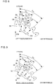
- FIG. 8 is an explanatory diagram about a way of obtaining the angle of a left tooth surface
- FIG. 9 is an explanatory diagram about a way of obtaining the angle of a right tooth surface
- FIG. 10 is an explanatory diagram about a way of obtaining the angle of a reference tooth groove
- FIG. 11 is an explanatory diagram about a correction method of the reference tooth groove angle.
- FIG. 12 (a) is a block diagram showing a configuration of a gear meshing angle detection device of a case according to the invention in which angles of both left and right tooth surfaces are obtained by using clock pulses
- FIG. 12 (b) is an explanatory diagram exemplary showing the relation among a starting point detection signal of a starting point detection sensor, the clock pulses, and an ON-OFF signal of a displacement sensor.
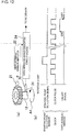
- FIG. 13 is a block diagram showing an outline of a circuit configuration of a high-speed meshing-dedicated circuit board
- FIG. 14 is a diagram showing an outline of state transition of the high-speed meshing-dedicated circuit board.
- a gear finishing machine such as a gear grinding machine has a main shaft 11 and a table shaft 12 (referred to as a C shaft) serving as a work rotating shaft.
- a grinding tool (a screw-like grindstone in the example shown in the drawing) 13 is attached to the main shaft 11, and a gear 14 which has undergone gear cutting by a gear cutting machine such as a hobbing machine and quenching is attached to the table shaft 12 as a work.
- the grinding tool 13 is driven by a main shaft motor 15 so as to rotate together with the main shaft 11 as by an arrow A3
- the work gear 14 is driven by a table shaft motor 16 so as to rotate together with the table shaft 12 as shown by an arrow A4.
- a Z-shaft drive unit for axially moving the grinding tool 13 as shown by an arrow A5
- an X-shaft drive unit for causing the grinding tool 13 to approach/get away from the work gear 14 as shown by an arrow A7
- finishing processing (grinding) of the work gear 14 can be performed by rotating the grinding tool 13 and the work gear 14 in the state in which teeth 17 (mountains and valleys) of the grinding tool 13 and teeth 18 (mountains and valleys) of the work gear 14 are meshed with each other.
- the meshing angle detection device of the present embodiment has a configuration having a displacement sensor (displacement sensor head 21 and displacement sensor amplifier 22) of an eddy current type, a rotary encoder 23 of an incremental type, and a high-speed meshing-dedicated circuit board 24.
- a displacement sensor displacement sensor head 21 and displacement sensor amplifier 22
- a rotary encoder 23 of an incremental type
- a high-speed meshing-dedicated circuit board 24 As shown in FIG. 2 , the meshing angle detection device of the present embodiment has a configuration having a displacement sensor (displacement sensor head 21 and displacement sensor amplifier 22) of an eddy current type, a rotary encoder 23 of an incremental type, and a high-speed meshing-dedicated circuit board 24.
- the rotary encoder 23 is coupled to the table shaft 12 via a rotating shaft 25 of the table shaft motor 16 and rotates together with the table shaft 12 (work gear 14) so as to output pulse signals of a Z phase, an A phase, and a B phase.
- a Z phase As shown in FIG. 7 , merely 1 pulse of the Z-phase pulse is output in one rotation, and the A-phase pulses and the B-phase pulses mutually have a phase difference of 90 degrees and output by a predetermined number of pulses in one rotation.
- the displacement sensor (gap sensor) is composed of the displacement sensor head 21 of a detection unit and the displacement sensor amplifier 22 of a signal processing unit. Since the displacement sensor is excellent in the sampling speed and repetition accuracy compared with conventional nearby sensors, it can detect the positions of both left and right tooth surfaces of the work gear 14 at a high speed and high accuracy and, since it is free from influence of hysteresis, can simultaneously detect the positions of both the left and right tooth surfaces of the work gear 14 merely by rotation of one direction.
- the displacement sensor head 21 is attached to a moving mechanism such as a turning mechanism, which is not shown, and, when the meshing angle is to be detected, it is caused to move (approach) to the vicinity of the teeth 18 of the work gear 14 attached to the table shaft 12 as shown in FIG. 2 by the moving mechanism so that it is disposed to face the teeth 18; meanwhile, when meshing angle detection is finished, it is moved to a standby position by the moving mechanism so that it does not disturb finishing processing by the grinding tool 13.
- a device which can simultaneously process analog signals (gap values) and digital signals (determination output of High-Low with respect to a threshold value) output from the displacement sensor head 21 is used as the displacement sensor amplifier.
- the detection signals of the displacement sensor are not output to the NC device 26 like conventional cases, but are output to the high-speed meshing-dedicated circuit board 24 so that a meshing angle obtained by the high-speed meshing-dedicated circuit board 24 is output to the NC device 26.
- the NC device 26 performs, for example, numerical value control of each shaft such as the main shaft 11 and the table shaft 12.
- a successive high-speed skip function of the NC device takes, for example, 24 msec or more for signal update of ON to OFF or OFF to ON with respect to input signals from outside.
- the displacement sensor can output an ON-OFF signal at a shortest interval (sampling speed) of, for example, 25 ⁇ sec. Therefore, in the combination of the displacement sensor and the NC device, the signal interval (input time) which can be processed on the NC device side is limited; therefore, the rotation speed of the work gear has to be reduced to detect the positions of both the left and right tooth surfaces; and, as a result, the excellent response speed (sampling speed) of the displacement sensor cannot be fully utilized.
- the meshing-dedicated circuit board 24 which can process the detection signals at a high speed and calculate the meshing angle, is developed and manufactured, and it is configured so that the detection signals (ON/OFF signals) of the displacement sensor are output to the high-speed meshing-dedicated circuit board 24.
- a clock see a clock unit 57 in FIG. 13
- a clock frequency of 40 kHz or more is mounted corresponding to the response speed (sampling speed) of the displacement sensor which is 25 ⁇ sec
- the computing speed of a processor (see a processor unit 49 of FIG. 13 ) mounted on the high-speed meshing-dedicated circuit board 24 is increased, thereby fully utilizing the ability of the displacement sensor side.
- FIG. 4 (a) shows a diagram in which a part of the teeth 18 and tooth grooves 27 of the work gear 14 is developed.
- the displacement sensor head 21 outputs a detection signal as shown in FIG. 4 (b) corresponding to the shape of the teeth 18 and tooth grooves 27 of the work gear 14.
- the displacement sensor head 21 detects the distances (gaps) from the displacement sensor head 21 to the teeth 18 and the tooth grooves 27.
- the detection signal (gap values) of the displacement sensor head 21 is, for example, an analog signal of -5 to +5 V.
- the displacement sensor amplifier 22 compares the detection signal as shown in FIG. 4 (b) and a trigger level (threshold value), which is set in advance, and outputs an ON-OFF signal of High or Low when the detection signal crosses the trigger level.
- the displacement sensor amplifier 22 in the shown example is set so as to output an OFF signal (Low signal) of 0 V when the detection signal crosses the trigger level from the state smaller than the trigger level to the state larger than that and output an ON signal (High signal) of 5 V when the detection signal crosses the trigger level from the state larger than the trigger level to the state smaller than that.
- the ON signal (High signal) is a position detection signal of the left tooth surface 28 of the work gear 14
- the OFF signal (Low signal) is a position detection signal of the right tooth surface 29 of the work gear 14.
- the trigger level can be set to an arbitrary value as long as it is within a range of a maximum value and a minimum value of the detection signal.
- the position detection signal of the left tooth surface 28 can be OFF signal (Low signal)
- the position detection signal of the left tooth surface 29 can be an ON signal (High signal).
- the ON-OFF signal output from the displacement sensor amplifier 22 is input to the high-speed meshing-dedicated circuit board 24, and the high-speed meshing-dedicated circuit board 24 obtains the meshing angle of the work gear 14 based on the ON-OFF signal, or the like.
- step S1 when the displacement sensor head 21 is caused to approach the work gear 14 by controlling the moving mechanism by the NC device 26 so as to achieve the state shown in FIG. 2 , and, for example, power is supplied to the high-speed meshing-dedicated circuit board 24 so as to complete preparation of the meshing angle detection process, the meshing angle detection process is started (step S1), and rotation of the table shaft 12 (work gear 14) is started by starting actuation of the table shaft motor 16 by the NC device 26 (step S2) .
- the rotation speed of the table shaft 12 (work gear 14) is not constant; therefore, the table shaft 12 (work gear 14) is excessively rotated more than 360 degrees.
- the rotation amount of the table shaft 12 (work gear 14) is 360 ⁇ 50 degrees as followings (step S3).
- the NC device 26 When power is turned off and the power is turned on again, the NC device 26 is not aware of the starting position (Z-phase position of the rotary encoder 23) of the table shaft 12; therefore, table shaft rotation for returning to the starting point is performed before performing table shaft rotation (step S2) for tooth surface position detection.
- the Z-phase position of the rotary encoder 23, that is, the starting point position of the table shaft 12 is confirmed by the Z-phase pulse (starting point signal) that is output from the rotary encoder 23 when the table shaft rotation for returning to the starting point is performed.
- the Z-phase pulse can be output from the rotary encoder 23 at the point of time when the table shaft 12 is rotated by 50 degrees from rotation start (point of time of 0 degree) or a point of time close to that; as a result, the tooth surface position detection can be reliably performed within the range (above described range of 0 degree to 360 degrees) in which the rotation speed of the table shaft 12 is stable.
- the high-speed meshing-dedicated circuit board 24 obtains the angles of both the left and right tooth surfaces (C 1 , C 2 , C 3 , C 4 , ⁇ C 2Z-1 , C 2Z ) based on the Z-phase pulse (starting point signal) (step S4) .
- the number of pulses of the A-phase pulses and the B-phase pulses output from the rotary encoder 23 during the period from when the Z-phase pulse (starting point signal) is output and until the ON signal (left tooth surface position detection signal) and the OFF signal (right tooth surface position detection signal) of the displacement sensor (displacement sensor amplifier 22) is output is counted.
- the counted values are converted into angles of both the both left and right tooth surfaces 28 and 29 based on predetermined relation between the pulse number of the rotary encoder 23 and the rotation angle, thereby obtaining the angles (C 1 , C 3 , ⁇ , C 2Z-1 ) of the left tooth surfaces 28 of all the teeth 18 from the Z phase (starting point) as exemplary shown in FIG.
- step S4 is a first process (means) .
- the Z phase of the rotary encoder 23 is used as the starting point of the table shaft 12 (work rotation shaft), the number of pulses of the A-phase pulses and the B-phase pulses output from the rotary encoder 23 is counted after the Z-phase pulse is output from the rotary encoder 23, and the counted values are latched (retained) by the ON-OFF signals (left tooth surface position detection signal and right tooth surface position detection signal) of the displacement sensor (displacement sensor head 21 and displacement sensor amplifier 22), thereby obtaining the left tooth surface angles and the right tooth surface angles from the starting point of the table shaft 12 (work rotation shaft) .
- a quad edge evaluation method see "measurement pitch" in FIG. 7 ) can be used as the counting method of the number of pulses of the A-phase pulses and the B-phase pulses.
- the angles of both the left and right tooth surfaces (C 1 , C 2 , C 3 , C 4 , ⁇ , C 2Z-1 , C 2Z ) of all the teeth 18 obtained herein are stored, the number of teeth Z of the work gear 14 is input (for example, an operator input by an input device which is not shown), and an initial value (0) of a minimum value ARmin of an accumulated pitch error ARi of all the right tooth surfaces 29 and an initial value (0) of a maximum value ALmax of an accumulated pitch error ALi of all the left tooth surfaces 28 are set (step S4).
- C 1 is set for the left tooth surface 28
- C 2 is set for the right tooth surface 29
- (C 2i-1 -C 1 ) is an accumulated pitch (actual measurement value) of the left tooth surfaces 28 as exemplary shown in FIG. 8
- (C 2i -C 2 ) is an accumulated pitch (actual measurement value) of the right tooth surfaces 29 as exemplary shown in FIG.
- step S5 2 is set as i (step S5).
- step S6 the value of C 2i-1 and the value of C 1 are compared with each other with respect to the left tooth surfaces 28 (step S6), the value of C 2i-1 is set as the value of C 2i-1 without modification when the value of C 2i-1 is larger than the value of C 1 (step S7), and the value of (C 2i-1 +360) is set as the value of C 2i-1 when the value of C 2i-1 is equal to or less than the value of C 1 (step S8) .
- step S9 based on the value of C 1 and the value of C 2i-1 set in step S7 or S8, according to the above described computing expression of ALi, the accumulated pitch ALi of the left tooth surfaces 28 is computed (step S9).
- step S10 the value of ALi obtained in step S9 and the value of ALmax are compared with each other (step S10).
- the value of ALmax is unchanged (step S12); and, when the value of ALi is equal to or larger than the value of ALmax, the value of the ALi is set as the value of ALmax (step S11).
- the value of C 2i and the value of C 2 are compared with each other (step S13).
- the value of C 2i is set as the value of C 2i without change (step S14) ; and, when the value of C 2i is equal to or less than the value of C 2 , the value of (C 2i +360) is set as the value of C 2i (step S15) .
- the accumulated pitch ARi of the left tooth surface 28 is computed according to the above described computing expression of ARi (step S16).
- step S8 or S15 when the value of C 2i-1 is determined to be equal to or less than the value of C 1 in step S6 or the value of C 2i is determined to be equal to or less than the value of C 2 in step S13, the process of step S8 or S15 is performed; thus, the value of (C 2i-1 -C 1 ) or (C 2i -C 2 ) is always a positive value in step S9 or S16.
- step S17 the value of ARi obtained in step S16 and the value of ARmin are compared with each other (step S17).
- step S17 the value of ARi is equal to or larger than the value of ARmin
- step S18 the value of ALmax is unchanged
- step S19 the value of ARi is set as the value of ARmin
- step S20 the value of i is caused to be (i+1) (step S20), and the processes of above described steps S6 to S12 and steps S13 to S19 are repeated until the value of i reaches the value of the number of teeth Z (step S21).
- step S5 to S21 are a second process (means) and a third process (means).
- step S22 is a fourth process (means) .
- the angle from the vertex (center portion in the width direction) of the tooth 18 to the vertex (center portion in the width direction) of the adjacent tooth 18 can be obtained by dividing 360 degrees by the number of teeth Z, and 1/2 of that is the position between the vertices of the two adjacent teeth 18, that is, the position of the reference tooth groove 27 (angle from the vertex of the tooth 18 to the reference tooth groove 27).
- the angle from the Z phase (starting point) to the vertex of the tooth 18 can be obtained by (C1+C2)/2. Therefore, the angle ⁇ 0 from the Z phase (starting point) to the reference tooth groove 27 can be obtained by the below expression.
- ⁇ 0 C 1 + C 2 / 2 + 360 / Z / 2
- step S23 is a fifth process (means).
- ⁇ ARmin + ALmax / 2
- the reference tooth groove angle ⁇ 0 has to be corrected.
- the correction amount ⁇ which satisfies the above described requirements, can be obtained by averaging the maximum accumulated pitch error ALmax (error largest in the positive direction) of the left tooth surfaces 28 and the minimum accumulated pitch error ARmin (largest error in the negative direction opposite to the arrow A10: largest absolute value) of the right tooth surfaces 29 by the above described expression and equalizing the accumulated pitch errors ALmax and ARmin in the left and right.
- dotted lines represent the tooth surfaces 28 and 29 of both the left and right sides of the reference tooth groove 27 of the case which is supposed to be an ideal case without accumulated pitch errors
- solid lines show the left tooth surface 28 having the maximum accumulated pitch error ALmax and the right tooth surface 29 having the minimum accumulated pitch error ARmin among all the tooth surfaces 28 and 29 virtually overlapped with the tooth surfaces 28 and 29 of the dotted lines, and the distance between both the left and right tooth surfaces 28 and 29 is the largest in this virtual state.
- the reason for obtaining the correction amount ⁇ based on the left tooth surface 28 having the maximum accumulated pitch error ALmax and the right tooth surface 29 having the minimum accumulated pitch error ARmin in this manner is that insufficiently ground portions are conceived to be most likely generated on the left tooth surface 28 and the right tooth surface 29.
- the NC device 26 controls the rotation of the table shaft motor 16 based on the detection signals (pulse signals) from the rotary encoder 23, thereby correcting the rotation phases of the grinding tool 13 (main shaft 11) and the work gear 14 (table shaft 12), which are rotated in synchronization with each other, merely by the correction amount ⁇ as exemplary shown in FIG. 11 .
- the rotation phases of the grinding tool 13 (main shaft 11) and the work gear 14 (table shaft 12) are caused to be optimal; and, when the drive units of each shaft are controlled in this state in the manner similar to conventional cases, the teeth (mountains and valleys) of the grinding tool 13 are meshed with the teeth 18 (mountains and valleys) of the work gear 14.
- meshing is completed, and actual finishing process is started.
- the angles of both the left and right tooth surfaces (C 1 , C 2 , C 3 , C 4 , ⁇ , C 2Z-1 , C 2Z ) are obtained based on the pulse signals of the rotary encoder 23; however, according to the invention, the angles of both the left and right tooth surfaces (C 1 , C 2 , C 3 , C 4 , ⁇ , C 2Z-1 , C 2Z ) are obtained based on the clock pulses transmitted from an internal clock equipped in the high-speed meshing-dedicated circuit board 24. In this case, a starting point detection means which outputs a starting point signal instead of the Z-phase pulse of the rotary encoder 23 is required.
- the starting point detection means in this case may have, for example, a configuration as shown in FIG. 12 as long as the starting point of the table shaft 12 (work rotation shaft) can be detected.
- a starting point projection 31 indicating a starting point of the table shaft 12 is provided at one location of the outer peripheral surface of the table shaft 12, and the starting point projection 31 is detected by an arbitrary starting point detection sensor 32 such as a nearby sensor or a displacement sensor.
- the starting point detection sensor 32 outputs a detection signal of the starting point projection 31 to the high-speed meshing-dedicated circuit board 24. That is, the starting point detection signal of the starting point detection sensor 32 serves as a substitute for the Z-phase pulse of the rotary encoder 23.
- the starting point projection 31 is not limited to the case in which it is directly provided on the table shaft 12 like the example shown in the drawing, and it may be provided on another rotation shaft coupled to the table shaft. More specifically, when another rotation shaft which is coupled to the table shaft 12 and rotates together with the table shaft 12 is provided, the starting point projection 31 indicating the starting point of the table shaft 12 can be provided at one location of the outer peripheral surface of the other rotation shaft.
- the high-speed meshing-dedicated circuit board 24 obtains the angles (C 1 , C 2 , C 3 , C 4 , ⁇ , C 2Z-1 , C 2Z ) of both the left and right tooth surfaces 28 and 29 based on the starting point detection signal.
- the number of pulses of clock pulses output from the clock during the period from when the starting point detection signal is output until the ON signal or the OFF signal of the displacement sensor (displacement sensor amplifier 22) is output is counted.
- the counted values are converted into the angles of both the left and right tooth surfaces 28 and 29 based on the relation between the number of pulses of the clock pulses and the rotation angles (relation between clock frequencies and the rotation speed of the table shaft 12), thereby obtaining the angles (C 1 , C 3 , ⁇ , C 2Z-1 ) of the left tooth surfaces 28 of all the teeth 18 from the starting point as well as FIG.
- the rotation speed of the work gear 14 is assumed to be constant, the number of pulses of the clock pulses (reference pulses) output from the internal clock after the starting point detection signal is output from a starting point detection means such as the starting point detection sensor 32 is counted, and the counted value is latched (retained) by the ON-OFF signals (left tooth surface position detection signal and right tooth face position detection signal) of the displacement sensor 22, thereby obtaining the left tooth surface angles and the right tooth surface angles from the starting point of the table shaft 12 (work rotation shaft).
- the setting of the rotation speed of the table shaft 12 may be switchable, for example, in two levels between a low-speed mode in which the work gear 14 is rotated at a low constant rotation speed and a high-speed mode in which it is rotated at a high constant rotation speed.
- the high-speed meshing-dedicated circuit board 24 has: input connector units 41, 42, 43, and 44 composed of connectors, or the like; an encoder signal input IF circuit unit 45 composed of an actuation input transistor, a resistor, a capacitor, or the like; an NC/starting point detection signal input IF circuit unit 46 composed of a photocoupler, a transistor, a resistor, a capacitor, or the like; a displacement sensor input IF circuit unit 47 composed of a photocoupler, a transistor, a resistor, a capacitor, or the like; a ROM unit 48 composed of a ROMIC, a resistor, a capacitor, or the like; a processor unit 49 composed of a micro processor, a capacitor, or the like; a DCDC conversion unit 50 composed of a DCDC converter, a capacitor, or the like; a 24 V power source unit 51 composed of a D power source, a capacitor, or the like; a power source input terminal base unit 52 composed of a
- External input wiring is connected to the input connector units 41, 42, 43, and 44.
- the encoder signal input IF circuit unit 45 the level of the input signal from the rotary encoder 23 is converted into a signal level for processor input (conversion from 5 V to 3.3 V).
- the NC/starting point detection signal input IF circuit unit 46 converts the level of the input signal from the NC device 26 or the starting point detection sensor 32 to a signal level for processor input (conversion from 5 V to 3.3 V).
- the displacement sensor input IF circuit unit 47 converts the level of the input signal from the displacement sensor amplifier 22 to the signal level for processor input (conversion from 5 V to 3.3 V).
- the ROM unit 48 stores a program (for example, a computing program of the meshing angle), and the program is loaded to the processor.
- the processor unit 49 performs the processes as shown in FIG. 14 based on the program.
- the DCDC conversion unit 50 supplies 3.3 V power to 3.3 V-based transistors.
- the 24 V power source unit 51 receives a voltage of 24 V and supplies a voltage of 5 V to 5 V-based transistors.
- the power source input terminal base unit 52 performs wiring connection of an external power source (DC 24 V).
- the reset switch unit 53 performs reset of the processor.
- the DIPSW unit 54 is for setting of the processor.
- the LED display unit 55 displays an operation state of the high-speed meshing-dedicated circuit board 24 by 7-segment LED display.
- the LED drive unit 56 drives display signals from the processor for LED.
- the clock unit 57 generates a reference clock pulse of the processor. The clock pulse is utilized also for obtaining the angles of both the left and right tooth surfaces 28 and 29 as described above.
- the SRAM unit 58 stores measurement data.
- the output IF unit 59 converts the output signal level of the processor from 3.3 V to 24 V.
- the output connector unit 60 connects external output wiring.
- FIG. 14 upon power source ON 61, power is supplied from an external power source, and READY output to the NC device 26 is performed.
- initialization 62 internal variables are cleared.
- an idle state 63 a command from the NC device 26 is waited for, and transition to a state corresponding to the command from the NC device 26 is made.
- data setting 64 the type of set data is identified, data corresponding to the type (for example, the number of teeth Z) is set, whether a part of the data (for example, the number of teeth Z) is within the range of specification or not is checked, and an error is output if it is out of the specification range.
- the maximum value and the minimum value of the accumulated pitch errors, the clock frequency of the high-speed meshing-dedicated circuit board 24, and the like are output to the NC device 26 in accordance with requests of the NC device 26, and whether the type of the requested data is within a specification range or not is checked, and an error is output if it is outside the specification range.
- a calculation process 66 calculation processes such as those shown in FIG. 5 and FIG. 6 are performed, whether the accumulated pitch error is excessively large or not is checked, and an error is output if it is excessive.
- error output 67 error information notification to the NC device 26 is performed.
- reference pulse count value acquisition 68 the A-phase pulses and the B-phase pulses of the rotary encoder 23 are counted when an encoder mode is selected, and the clock pulses are counted when a low-speed/high-speed mode is selected.
- display 69 in accordance with DIPSW of the high-speed meshing-dedicated circuit board 24, each data or error information is displayed.
- the gear meshing angle detection device of the present embodiment includes a first means of obtaining left tooth surface angles (C 1 , C 3 , ⁇ , C 2Z-1 ) and right tooth surface angles (C 2 , C 4 , ⁇ , C 2Z ) from a starting point of the table shaft 12 for all teeth 18 of the work gear 14; a second means of obtaining a left tooth surface accumulated pitch error ALi and a right tooth surface accumulated pitch error ARi for all the teeth 18 based on the left tooth surface angles (C 1 , C 3 , ⁇ , C 2Z-1 ) and the right tooth surface angles (C 2 , C 4 , ⁇ , C 2Z ); a third means of obtaining a left tooth surface maximum accumulated pitch error ALmax and a right tooth surface minimum accumulated pitch error ARmin from the left tooth surface accumulated pitch error ALi and the right tooth surface accumulated pitch error ARi wherein the clockwise direction of the work gear 14 is as a positive direction; a fourth means of obtaining an angle ⁇
- the correction value ⁇ is obtained based on the left tooth surface 28 having the maximum accumulated pitch error ALmax (when clockwise direction is a positive direction) and the right tooth surface 29 having the minimum accumulated pitch error ARmin (when clockwise direction is a positive direction), which are conceived to most likely generate insufficiently ground portions.
- the reference tooth groove angle ⁇ 0 is corrected by the correction value ⁇ , thereby obtaining the meshing angle ⁇ of the work gear 14. Therefore, the optimal meshing angle ⁇ which can cancel the accumulated pitch errors of both the left and right tooth surfaces 28 and 29, prevent generation of insufficiently ground portions on both the left and right tooth surfaces 28 and 29, and reduce the grinding allowance of both the left and right tooth surfaces 28 and 29 as much as possible can be obtained.
- a gear meshing angle detection device not according to the invention is characterized in that, in the first process (means), the Z phase of the rotary encoder 23 is used as the starting point of the table shaft 12 (work rotation shaft), the number of pulses of the A-phase pulse and the B-phase pulse which are output from the rotary encoder after the Z-phase pulse is output from the rotary encoder 23 is counted, and the counted values are latched (retained) by ON-OFF signals (the left tooth surface position detection signal and the right tooth surface position detection signal) of the displacement sensor (displacement sensor head 21 and displacement sensor amplifier 22) so as to obtain the left tooth surface angles (C 1 , C 3 , ⁇ , C 2Z-1 ) and the right tooth surface angle (C 2 , C 4 , ⁇ , C 2Z ) from the starting point of the table shaft 12 (the work rotation shaft) . Therefore, both the left and right tooth surface angles of all the teeth 18 (C 1 , C 2 , C 3 , C 4 ,
- the gear meshing angle detection device of the present invention is characterized in that, in the first process (means), the number of pulses of the clock pulse (reference pulse) output from the internal clock is counted after the starting point detection signal is output from the starting point detection means such as the starting point detection sensor 32, and the counted value is latched (retained) by the ON-OFF signals (the left tooth surface position detection signal and the right tooth surface position detection signal) of the displacement sensor 22 so as to obtain the left tooth surface angles (C 1 , C 3 , ⁇ , C 2Z-1 ) and the right tooth surface angles (C 2 , C 4 , ⁇ , C 2Z ) from the starting point of the table shaft 12 (the work rotation shaft). Therefore, both the left and right tooth surface angles (C 1 , C 2 , C 3 , C 4 , ⁇ , C 2Z-1 , C 2Z ) of all the teeth 18 can be detected at high accuracy and at a high speed.
- the gear meshing angle detection device of a preferable embodiment is characterized in that the first means, the second means, the third means, the fourth means, the fifth means, and the sixth means are calculation processing programs executed by a processor (processor unit 49) mounted in the high-speed meshing-dedicated circuit board 24, and a clock (clock unit 57) of a clock frequency which can handle a response speed of the displacement sensor is mounted on the meshing-dedicated circuit board. Therefore, both the left and right tooth surface angles (C 1 , C 2 , C 3 , C 4 , ⁇ , C 2Z-1 , C 2Z ) of all the teeth 18 can be detected at a significantly high speed by fully utilizing the excellent response speed (sampling speed) of the displacement sensor.
- a processor processor unit 49
- clock clock unit 57
- the present invention relates to a gear meshing angle detection method and device, which are effective in application to, for example, the cases in which meshing is performed at a high speed and at high accuracy in a gear finishing machine such as a gear grinding machine so as to perform highly accurate finishing processing of a gear.
Landscapes
- Engineering & Computer Science (AREA)
- Mechanical Engineering (AREA)
- Gear Processing (AREA)
- Measurement Of Length, Angles, Or The Like Using Electric Or Magnetic Means (AREA)
- Transmission And Conversion Of Sensor Element Output (AREA)
- Length Measuring Devices With Unspecified Measuring Means (AREA)
Claims (3)
- Verzahnungseingriffswinkel-Erfassungsverfahren, welches einen Eingriffswinkel eines an einer Arbeitsdrehwelle (12) angebrachten Arbeitszahnrads (14) erfasst, umfassend:einen ersten Prozess (S4) zum Erhalten eines linken Zahnoberflächenwinkels und eines rechten Zahnoberflächenwinkels von einem Startpunkt der Arbeitsdrehwelle für alle Zähne (18) des Arbeitszahnrads;einen zweiten Prozess (S5 bis S21) zum Erhalten eines akkumulierten Steigungsfehlers einer linken Zahnoberfläche und eines akkumulierten Steigungsfehlers einer rechten Zahnoberfläche für alle Zähne basierend auf dem linken Zahnoberflächenwinkel und dem rechten Zahnoberflächenwinkel;einen dritten Prozess (S5 bis S21) zum Erhalten eines maximalen akkumulierten Steigungsfehlers einer linken Zahnoberfläche (ALmax) und eines minimalen akkumulierten Steigungsfehlers einer rechten Zahnoberfläche (ARmin) aus dem akkumulierten Steigungsfehler einer linken Zahnoberfläche und dem akkumulierten Steigungsfehler einer rechten Zahnoberfläche, wobei die Richtung des Arbeitszahnrads im Uhrzeigersinn eine positive Richtung ist;einen vierten Prozess (S22) zum Erhalten eines Winkels (θ0) einer Bezugszahnnut basierend auf dem linken Zahnoberflächenwinkel und dem rechten Zahnoberflächenwinkel;einen fünften Prozess (S23) zum Mitteln des maximalen akkumulierten Steigungsfehlers der linken Zahnoberfläche und des minimalen akkumulierten Steigungsfehlers der rechten Zahnoberfläche, um einen Korrekturwert (δθ) eines Winkels der Bezugszahnnut zu erhalten; undeinen sechsten Prozess (S24) zum Korrigieren des Bezugszahnnutwinkels durch den Korrekturwert, um den Verzahnungswinkel (θ) zu erhalten,gekennzeichnet durcheine Startpunkt-Erfassungseinrichtung (32), welche den Startpunkt der Arbeitsdrehwelle (12) erfasst und ein Startpunkt-Erfassungssignal ausgibt, wenn sich die Arbeitsdrehwelle in einer Richtung dreht,einen Taktgeber (57), welcher einen Taktimpuls ausgibt, undeinen Versatzsensor (21, 22), welcher die Positionen der linken Zahnoberfläche (28) und der rechten Zahnoberfläche (29) aller Zähne (18) des Arbeitszahnrads (14) erfasst und ein Positionserfassungssignal der linken Zahnoberfläche und ein Positionserfassungssignal der rechten Zahnoberfläche ausgibt, wenn sich das Arbeitszahnrad in einer Richtung zusammen mit der Arbeitsdrehwelle dreht; undin dem ersten Prozess die Anzahl von Impulsen des von dem Taktgeber ausgegebenen Taktimpulses gezählt wird, nachdem das Startpunkt-Erfassungssignal von der Startpunkt-Erfassungseinrichtung ausgegeben worden ist, und der gezählte Wert durch das Positionserfassungssignal der linken Zahnoberfläche und das Positionserfassungssignal der rechten Zahnoberfläche des Versatzsensors verriegelt wird, um den linken Zahnoberflächenwinkel und den rechten Zahnoberflächenwinkel von dem Startpunkt der Arbeitsdrehwelle zu erhalten.
- Verzahnungseingriffswinkel-Erfassungsvorrichtung zum Erfassen eines Verzahnungswinkels eines an einer Arbeitsdrehwelle (12) angebrachten Arbeitszahnrads (14), umfassend:eine erste Einrichtung zum Erhalten eines linken Zahnoberflächenwinkels und eines rechten Zahnoberflächenwinkels von einem Startpunkt der Arbeitsdrehwelle für alle Zähne (18) des Arbeitszahnrads;eine zweite Einrichtung zum Erhalten eines akkumulierten Steigungsfehlers einer linken Zahnoberfläche und eines akkumulierten Steigungsfehlers einer rechten Zahnoberfläche für alle Zähne basierend auf dem linken Zahnoberflächenwinkel und dem rechten Zahnoberflächenwinkel;eine dritte Einrichtung zum Erhalten eines maximalen akkumulierten Steigungsfehlers der linken Zahnoberfläche (ALmax) und eines minimalen akkumulierten Steigungsfehlers der rechten Zahnoberfläche (ARmin) aus dem akkumulierten Steigungsfehler der linken Zahnoberfläche und dem akkumulierten Steigungsfehler der rechten Zahnoberfläche, wobei die Richtung des Arbeitszahnrads im Uhrzeigersinn eine positive Richtung ist;eine vierte Einrichtung zum Erhalten eines Winkels (θ0) einer Bezugszahnnut basierend auf dem linken Zahnoberflächenwinkel und dem rechten Zahnoberflächenwinkel;eine fünfte Einrichtung zum Mitteln des maximalen akkumulierten Steigungsfehlers der linken Zahnoberfläche und des minimalen akkumulierten Steigungsfehlers der rechten Zahnoberfläche, um einen Korrekturwert (δθ) eines Winkels der Bezugszahnnut zu erhalten; undeine sechste Einrichtung zum Korrigieren des Bezugszahnnutwinkels durch den Korrekturwert, um den Verzahnungswinkel (θ) zu erhalten,gekennzeichnet durcheine Startpunkt-Erfassungseinrichtung (32), welche den Startpunkt der Arbeitsdrehwelle (12) erfasst und ein Startpunkt-Erfassungssignal ausgibt, wenn sich die Arbeitsdrehwelle in einer Richtung dreht,einen Taktgeber (57), welcher einen Taktimpuls ausgibt, undeinen Versatzsensor (21, 22), welcher die Positionen der linken Zahnoberfläche (28) und der rechten Zahnoberfläche (29) aller Zähne (18) des Arbeitszahnrads (14) erfasst und ein Positionserfassungssignal der linken Zahnoberfläche und ein Positionserfassungssignal der rechten Zahnoberfläche ausgibt, wenn das Arbeitszahnrad in einer Richtung zusammen mit der Arbeitsdrehwelle gedreht wird; undin der ersten Einrichtung die Anzahl von Impulsen des von dem Taktgeber ausgegebenen Taktimpulses gezählt wird, nachdem das Startpunkt-Erfassungssignal von der Startpunkt-Erfassungseinrichtung ausgegeben worden ist, und der gezählte Wert durch das Positionserfassungssignal der linken Zahnoberfläche und das Positionserfassungssignal der rechten Zahnoberfläche des Versatzsensors verriegelt wird, um den linken Zahnoberflächenwinkel und den rechten Zahnoberflächenwinkel von dem Startpunkt der Arbeitsdrehwelle zu erhalten.
- Verzahnungseingriffswinkel-Erfassungsvorrichtung nach Anspruch 2, wobei
eine dedizierte Verzahnungsschaltungsplatte (24) vorgesehen ist, und
die erste Einrichtung, die zweite Einrichtung, die dritte Einrichtung, die vierte Einrichtung, die fünfte Einrichtung und die sechste Einrichtung Berechnungsverarbeitungsprogramme darstellen, die durch einen in der dedizierten Verzahnungsschaltungsplatte angebrachten Prozessor (49) ausgeführt werden, und ein Taktgeber (57) einer Taktfrequenz, welche eine Antwortgeschwindigkeit des Versatzsensors handhaben kann, auf der dedizierten Verzahnungsschaltungsplatte angebracht ist.
Applications Claiming Priority (2)
| Application Number | Priority Date | Filing Date | Title |
|---|---|---|---|
| JP2006295773A JP4865506B2 (ja) | 2006-10-31 | 2006-10-31 | 歯車の歯合わせ角度検出方法及び装置 |
| PCT/JP2007/070776 WO2008053769A1 (en) | 2006-10-31 | 2007-10-25 | Method and device for detecting tooth matching angle of gear |
Publications (3)
| Publication Number | Publication Date |
|---|---|
| EP2072166A1 EP2072166A1 (de) | 2009-06-24 |
| EP2072166A4 EP2072166A4 (de) | 2014-02-19 |
| EP2072166B1 true EP2072166B1 (de) | 2019-02-27 |
Family
ID=39344111
Family Applications (1)
| Application Number | Title | Priority Date | Filing Date |
|---|---|---|---|
| EP07830510.9A Active EP2072166B1 (de) | 2006-10-31 | 2007-10-25 | Verfahren und vorrichtung zur erkennung des richtigen winkels eines getriebes im verhältnis zu einem zahn |
Country Status (6)
| Country | Link |
|---|---|
| US (1) | US8463575B2 (de) |
| EP (1) | EP2072166B1 (de) |
| JP (1) | JP4865506B2 (de) |
| KR (1) | KR101106889B1 (de) |
| CN (1) | CN101173864B (de) |
| WO (1) | WO2008053769A1 (de) |
Families Citing this family (43)
| Publication number | Priority date | Publication date | Assignee | Title |
|---|---|---|---|---|
| JP4865579B2 (ja) | 2007-02-06 | 2012-02-01 | 三菱重工業株式会社 | 歯合わせ装置及び歯車加工機械 |
| JP4882023B2 (ja) * | 2008-03-19 | 2012-02-22 | 平田機工株式会社 | ワーク検査搬送装置 |
| KR100941579B1 (ko) * | 2009-08-14 | 2010-02-10 | 에스앤티중공업 주식회사 | 호빙머신의 기어 위상측정장치를 이용한 스카이빙 가공방법 및 위치측정 오류 판별방법 |
| JP5511263B2 (ja) * | 2009-08-24 | 2014-06-04 | 三菱重工業株式会社 | 内歯車加工方法及び内歯車加工機 |
| EP2484489B1 (de) * | 2009-09-28 | 2018-10-31 | Mitsubishi Heavy Industries Machine Tool Co., Ltd. | Verfahren zur synchronisierung eines gewindeschleifsteins sowie vorrichtung dafür |
| WO2011043225A1 (ja) * | 2009-10-05 | 2011-04-14 | 本田技研工業株式会社 | 歯面振れ測定装置及び歯面振れ測定方法、研削工具成形装置及び研削工具成形方法、並びに、歯車研削装置の歯合わせ方法 |
| JP5308404B2 (ja) * | 2010-06-16 | 2013-10-09 | 三菱重工業株式会社 | 歯車研削方法 |
| WO2011158385A1 (ja) * | 2010-06-18 | 2011-12-22 | 株式会社牧野フライス製作所 | 歯車の研削加工方法および加工装置 |
| CN102135470B (zh) * | 2010-12-24 | 2012-12-19 | 成都工具研究所有限公司 | 直线测头式小齿轮误差差动测量方法 |
| DE102011079384B4 (de) * | 2011-07-19 | 2013-09-26 | Trimble Jena Gmbh | Verfahren und Vorrichtung zum Bestimmen einer Qualität einer Getriebeanordnung aus mindestens zwei Getrieberädern |
| KR101283826B1 (ko) * | 2012-03-22 | 2013-07-08 | 주식회사 피티엠 | 차동기어 어셈블리의 치면 검사방법 |
| CN102607635B (zh) * | 2012-04-06 | 2014-07-09 | 上海烟草机械有限责任公司 | 一种应用于滚筒式涂胶器啮合检测的测量系统 |
| DK2909471T3 (en) * | 2012-10-19 | 2016-12-05 | Vestas Wind Sys As | Wind turbine comprising a technical floor |
| ITBO20130263A1 (it) * | 2013-05-27 | 2014-11-28 | Samp Spa Con Unico Socio | Macchina e metodo per la finitura di ingranaggi |
| CN103389206B (zh) * | 2013-07-26 | 2016-01-06 | 西安工业大学 | 一种齿轮测量中心上小模数齿轮的测量方法 |
| CN104569493B (zh) * | 2013-10-24 | 2018-09-07 | 大陆汽车电子(长春)有限公司 | 齿距误差测试系统 |
| JP5872532B2 (ja) * | 2013-12-27 | 2016-03-01 | 本田技研工業株式会社 | 歯車研削補正データ作成方法 |
| JP5595613B1 (ja) * | 2014-03-20 | 2014-09-24 | 三菱重工業株式会社 | 歯車の位相算出装置、歯車の位相算出方法、及び、歯車加工装置 |
| CN104075888B (zh) * | 2014-06-27 | 2016-05-04 | 北京控制工程研究所 | 一种利用电噪声测量齿轮啮合侧隙的装置及方法 |
| DE102015104289B4 (de) * | 2015-03-23 | 2016-12-15 | Klingelnberg Ag | Verfahren zum Betreiben einer verzahnungsbearbeitenden Maschine |
| CN104807490B (zh) * | 2015-03-31 | 2017-08-18 | 华中科技大学无锡研究院 | 一种旋转编码开关检测方法 |
| CN104915711B (zh) * | 2015-07-10 | 2017-11-14 | 江苏理工学院 | 绝对角度计数器 |
| KR20170009006A (ko) | 2015-07-15 | 2017-01-25 | 김도훈 | 에너지 저감형 친환경 지하 건축구조 |
| CN106862975A (zh) * | 2017-02-20 | 2017-06-20 | 重庆机床(集团)有限责任公司 | 一种激光自动对齿方法 |
| CN107246966A (zh) * | 2017-06-30 | 2017-10-13 | 太仓宝达齿条有限公司 | 一种齿轮运转情况监测设备 |
| JP6969367B2 (ja) * | 2017-12-27 | 2021-11-24 | 株式会社ジェイテクト | 歯車加工装置 |
| CN108470102B (zh) * | 2018-03-21 | 2021-10-22 | 西安科技大学 | 一种面向啮合性能预控的小轮齿面设计方法及加工方法 |
| DE102018112805A1 (de) * | 2018-05-29 | 2019-12-05 | Klingelnberg Gmbh | Verfahren zur Analyse von Oberflächenwelligkeiten |
| JP2020019126A (ja) * | 2018-08-03 | 2020-02-06 | 株式会社不二越 | 自動バリ取りおよび/またはエッジ仕上げ装置、ならびにバリ取りおよび/またはエッジ仕上げの自動化方法 |
| JP6466633B1 (ja) | 2018-08-10 | 2019-02-06 | ヤマザキマザック株式会社 | 歯車の位相検出方法、歯車の製造方法、ワークのエッジの位置検出方法、および歯車の位相を検出する工作機械 |
| CN109149868B (zh) * | 2018-08-30 | 2021-01-05 | 奇瑞汽车股份有限公司 | 一种防夹电机转角信号检测机构及其检测方法 |
| CN109520460B (zh) * | 2018-12-25 | 2024-08-30 | 德恩科电机(常州)有限公司 | 一种行星齿轮齿数检测机 |
| CN109732595B (zh) * | 2018-12-29 | 2021-02-09 | 深圳市越疆科技有限公司 | 一种舵机的校准方法、装置及控制器 |
| JP7237422B2 (ja) * | 2019-01-11 | 2023-03-13 | ジヤトコ株式会社 | 検査装置 |
| CN109798928B (zh) * | 2019-01-23 | 2022-01-28 | 长春理工大学 | 基于转角互逆的轴角编码器全量程精度检测方法 |
| CN109883487A (zh) * | 2019-03-29 | 2019-06-14 | 北京航空航天大学 | 一种高精度高速直线测距测速装置 |
| EP3795955B1 (de) * | 2019-09-23 | 2023-01-04 | Melexis Technologies SA | Magnetisches positionssensorsystem |
| DE102019006809A1 (de) * | 2019-09-30 | 2021-04-01 | Gleason-Pfauter Maschinenfabrik Gmbh | Verfahren der schneidenden Erzeugung oder Bearbeitung einer jeweils gleichen Verzahnung an mehreren Werkstücken |
| CN112706088B (zh) * | 2019-10-24 | 2022-11-29 | 长春设备工艺研究所 | 一种轴齿齿端自动对齿的方法 |
| JP7456191B2 (ja) * | 2020-02-28 | 2024-03-27 | 株式会社ジェイテクト | 歯車加工装置及び歯車加工方法 |
| JP7724182B2 (ja) * | 2022-04-13 | 2025-08-15 | 三菱重工業株式会社 | 駆動機構、制御棒駆動装置および原子炉 |
| CN116048001A (zh) * | 2023-03-10 | 2023-05-02 | 南京工业大学 | 一种基于齿距误差的数控磨齿机准静态关键误差识别方法 |
| CN117381073A (zh) * | 2023-09-21 | 2024-01-12 | 上海径驰精密工具有限公司 | 一种热后齿轮精加工使用的cbn圆柱车齿刀及加工方法 |
Family Cites Families (15)
| Publication number | Priority date | Publication date | Assignee | Title |
|---|---|---|---|---|
| US3924721A (en) * | 1974-10-11 | 1975-12-09 | Burroughs Corp | Digital logic and servo system for print head rotate control |
| DE2855857C2 (de) * | 1978-12-22 | 1982-12-23 | Liebherr-Verzahntechnik Gmbh, 8960 Kempten | Verfahren zum Bearbeiten der Zahnflanken von schrägverzahnten Stirnrädern und Vorrichtung zur Durchführung des Verfahrens |
| US4920703A (en) * | 1986-06-04 | 1990-05-01 | Koganei Seiki Seisakusho | Method and apparatus for finishing a tooth surface of a gear |
| US5136522A (en) * | 1990-06-13 | 1992-08-04 | The Gleason Works | Stock dividing method and apparatus for gear manufacturing machine |
| JPH04336915A (ja) * | 1991-05-09 | 1992-11-25 | Nachi Fujikoshi Corp | Nc装置の歯合わせ方法 |
| DE4133539C1 (en) * | 1991-10-10 | 1993-05-06 | Jos. Koepfer & Soehne Gmbh, 7743 Furtwangen, De | Machine tool positioning system - determines position of groove on workpiece, giving voltage corresp. to circumference, and angular position of tool spindle, and uses phase difference between two sets of signals to position motors |
| DE4321448C2 (de) * | 1993-06-29 | 1995-08-31 | Kapp Werkzeugmasch | Verfahren zur Ermittlung des Summenteilungsfehlers eines zu bearbeitenden Zahnrades |
| JP3132740B2 (ja) * | 1993-11-26 | 2001-02-05 | 本田技研工業株式会社 | 歯車加工装置における歯車噛合方法 |
| JP3688381B2 (ja) * | 1995-03-10 | 2005-08-24 | 株式会社東芝 | 光ディスク原盤露光装置 |
| US20020124663A1 (en) * | 1999-04-07 | 2002-09-12 | Yoshitomo Tokumoto | Rotational angle detecting device, torque detecting device and steering apparatus |
| JP3980218B2 (ja) * | 1999-05-14 | 2007-09-26 | 豊精密工業株式会社 | 歯車ピッチ誤差取得方法 |
| JP2000326141A (ja) | 1999-05-19 | 2000-11-28 | Okamoto Machine Tool Works Ltd | 歯車研削装置の歯合わせ方法 |
| US6530550B1 (en) * | 2000-09-13 | 2003-03-11 | Nextengine, Inc. | Wireless turntable |
| JP4452431B2 (ja) * | 2002-06-24 | 2010-04-21 | 株式会社カシフジ | 歯車加工機械 |
| DE10342495B4 (de) | 2003-09-12 | 2017-02-02 | Reishauer Ag | Verfahren und Vorrichtung zum Einzentrieren von vorverzahnten Werkstücken auf Verzahnungsfeinbearbeitungsmaschinen |
-
2006
- 2006-10-31 JP JP2006295773A patent/JP4865506B2/ja active Active
-
2007
- 2007-10-25 WO PCT/JP2007/070776 patent/WO2008053769A1/ja not_active Ceased
- 2007-10-25 KR KR1020097008799A patent/KR101106889B1/ko not_active Expired - Fee Related
- 2007-10-25 EP EP07830510.9A patent/EP2072166B1/de active Active
- 2007-10-25 US US12/445,524 patent/US8463575B2/en active Active
- 2007-10-31 CN CN200710167997XA patent/CN101173864B/zh active Active
Non-Patent Citations (1)
| Title |
|---|
| None * |
Also Published As
| Publication number | Publication date |
|---|---|
| US8463575B2 (en) | 2013-06-11 |
| US20100023297A1 (en) | 2010-01-28 |
| WO2008053769A1 (en) | 2008-05-08 |
| EP2072166A4 (de) | 2014-02-19 |
| JP2008110445A (ja) | 2008-05-15 |
| CN101173864B (zh) | 2011-03-02 |
| KR20090068352A (ko) | 2009-06-26 |
| JP4865506B2 (ja) | 2012-02-01 |
| EP2072166A1 (de) | 2009-06-24 |
| KR101106889B1 (ko) | 2012-01-25 |
| CN101173864A (zh) | 2008-05-07 |
Similar Documents
| Publication | Publication Date | Title |
|---|---|---|
| EP2072166B1 (de) | Verfahren und vorrichtung zur erkennung des richtigen winkels eines getriebes im verhältnis zu einem zahn | |
| US11471990B2 (en) | Method for optical measurement | |
| KR101721969B1 (ko) | 기어들에서 인벌류트들의 위치 결정을 위한 방법 | |
| US10722994B2 (en) | Method for the automatic determination of the geometrical dimensions of a tool in a gear cutting machine | |
| JP3143310B2 (ja) | 位置検出装置、補正機能付位置検出装置、位置検出方法、および、位置検出装置の補正方法 | |
| EP1970672A2 (de) | Positionsdetektor | |
| CN109782815B (zh) | 基于多轴联动系统的复杂型面自适应测量路径规划方法 | |
| CN110989493A (zh) | 干扰成分确定方法和干扰成分确定装置 | |
| JP2003089058A (ja) | プロフィル補正方法、数値制御装置および工作機械 | |
| CN102937420B (zh) | 凸轮轮廓检测系统 | |
| JP2013031918A (ja) | 駆動部間の結合が自由に定められる機械を制御する方法 | |
| JP3129923B2 (ja) | ホブ盤の歯車仕上げ加工方法 | |
| CN110989492A (zh) | 齿轮加工机的控制装置 | |
| JPH04336915A (ja) | Nc装置の歯合わせ方法 | |
| TW202410994A (zh) | 具有用於校準嚙合感測器之校準裝置的工具機 | |
| JP4121875B2 (ja) | アブソリュート位置検出装置 | |
| JP3072693B2 (ja) | 歯車形状の測定方法 | |
| CA1323699C (en) | Method of detecting a position of a robot | |
| JPH0625705B2 (ja) | 歯車の打痕値測定装置 | |
| CN102252631B (zh) | 基于直驱式电机的凸轮轮廓检测系统 | |
| JP2727542B2 (ja) | アーム位置検出方法 | |
| JP2694019B2 (ja) | ワークの溝幅の中心位置検出装置 | |
| JPS60256802A (ja) | ロボツトの位置補正システム | |
| JP2026013779A (ja) | 工作機械、歯車計測装置、誤差計測方法、歯車製造方法、及び、コンピュータプログラム | |
| JP2023046754A (ja) | バリ取り/エッジ仕上げ方法およびバリ取り/エッジ仕上げ装置 |
Legal Events
| Date | Code | Title | Description |
|---|---|---|---|
| PUAI | Public reference made under article 153(3) epc to a published international application that has entered the european phase |
Free format text: ORIGINAL CODE: 0009012 |
|
| 17P | Request for examination filed |
Effective date: 20090330 |
|
| AK | Designated contracting states |
Kind code of ref document: A1 Designated state(s): AT BE BG CH CY CZ DE DK EE ES FI FR GB GR HU IE IS IT LI LT LU LV MC MT NL PL PT RO SE SI SK TR |
|
| AX | Request for extension of the european patent |
Extension state: AL BA HR MK RS |
|
| DAX | Request for extension of the european patent (deleted) | ||
| RBV | Designated contracting states (corrected) |
Designated state(s): DE IT |
|
| A4 | Supplementary search report drawn up and despatched |
Effective date: 20140122 |
|
| RIC1 | Information provided on ipc code assigned before grant |
Ipc: B23F 23/12 20060101ALI20140116BHEP Ipc: B23F 5/04 20060101ALI20140116BHEP Ipc: B23F 23/00 20060101AFI20140116BHEP |
|
| RAP1 | Party data changed (applicant data changed or rights of an application transferred) |
Owner name: MITSUBISHI HEAVY INDUSTRIES MACHINE TOOL CO., LTD. |
|
| 17Q | First examination report despatched |
Effective date: 20170127 |
|
| GRAP | Despatch of communication of intention to grant a patent |
Free format text: ORIGINAL CODE: EPIDOSNIGR1 |
|
| INTG | Intention to grant announced |
Effective date: 20180905 |
|
| GRAS | Grant fee paid |
Free format text: ORIGINAL CODE: EPIDOSNIGR3 |
|
| GRAA | (expected) grant |
Free format text: ORIGINAL CODE: 0009210 |
|
| AK | Designated contracting states |
Kind code of ref document: B1 Designated state(s): DE IT |
|
| REG | Reference to a national code |
Ref country code: DE Ref legal event code: R096 Ref document number: 602007057723 Country of ref document: DE |
|
| REG | Reference to a national code |
Ref country code: DE Ref legal event code: R097 Ref document number: 602007057723 Country of ref document: DE |
|
| PLBE | No opposition filed within time limit |
Free format text: ORIGINAL CODE: 0009261 |
|
| STAA | Information on the status of an ep patent application or granted ep patent |
Free format text: STATUS: NO OPPOSITION FILED WITHIN TIME LIMIT |
|
| 26N | No opposition filed |
Effective date: 20191128 |
|
| P01 | Opt-out of the competence of the unified patent court (upc) registered |
Effective date: 20230519 |
|
| PGFP | Annual fee paid to national office [announced via postgrant information from national office to epo] |
Ref country code: DE Payment date: 20251020 Year of fee payment: 19 |
|
| PGFP | Annual fee paid to national office [announced via postgrant information from national office to epo] |
Ref country code: IT Payment date: 20251031 Year of fee payment: 19 |