EP2068444B1 - Oberflächenwellenfilter - Google Patents
Oberflächenwellenfilter Download PDFInfo
- Publication number
- EP2068444B1 EP2068444B1 EP07792891.9A EP07792891A EP2068444B1 EP 2068444 B1 EP2068444 B1 EP 2068444B1 EP 07792891 A EP07792891 A EP 07792891A EP 2068444 B1 EP2068444 B1 EP 2068444B1
- Authority
- EP
- European Patent Office
- Prior art keywords
- acoustic wave
- idt
- idts
- overlap width
- wave filter
- Prior art date
- Legal status (The legal status is an assumption and is not a legal conclusion. Google has not performed a legal analysis and makes no representation as to the accuracy of the status listed.)
- Active
Links
- 230000001902 propagating effect Effects 0.000 claims description 33
- 238000010897 surface acoustic wave method Methods 0.000 claims description 25
- 238000003780 insertion Methods 0.000 description 14
- 230000037431 insertion Effects 0.000 description 14
- 230000000052 comparative effect Effects 0.000 description 8
- 239000010408 film Substances 0.000 description 8
- VYPSYNLAJGMNEJ-UHFFFAOYSA-N Silicium dioxide Chemical compound O=[Si]=O VYPSYNLAJGMNEJ-UHFFFAOYSA-N 0.000 description 6
- 239000000758 substrate Substances 0.000 description 3
- 229910003327 LiNbO3 Inorganic materials 0.000 description 2
- 230000001413 cellular effect Effects 0.000 description 2
- 229910052681 coesite Inorganic materials 0.000 description 2
- 229910052906 cristobalite Inorganic materials 0.000 description 2
- 230000000694 effects Effects 0.000 description 2
- 239000002184 metal Substances 0.000 description 2
- 239000000377 silicon dioxide Substances 0.000 description 2
- 229910052682 stishovite Inorganic materials 0.000 description 2
- 229910052905 tridymite Inorganic materials 0.000 description 2
- 229910012463 LiTaO3 Inorganic materials 0.000 description 1
- 239000000919 ceramic Substances 0.000 description 1
- 239000007772 electrode material Substances 0.000 description 1
- 230000002349 favourable effect Effects 0.000 description 1
- 238000010030 laminating Methods 0.000 description 1
- 238000000034 method Methods 0.000 description 1
- 239000010453 quartz Substances 0.000 description 1
- 229910052814 silicon oxide Inorganic materials 0.000 description 1
- 239000010409 thin film Substances 0.000 description 1
Images


Classifications
-
- H—ELECTRICITY
- H03—ELECTRONIC CIRCUITRY
- H03H—IMPEDANCE NETWORKS, e.g. RESONANT CIRCUITS; RESONATORS
- H03H9/00—Networks comprising electromechanical or electro-acoustic devices; Electromechanical resonators
- H03H9/46—Filters
- H03H9/64—Filters using surface acoustic waves
-
- H—ELECTRICITY
- H03—ELECTRONIC CIRCUITRY
- H03H—IMPEDANCE NETWORKS, e.g. RESONANT CIRCUITS; RESONATORS
- H03H9/00—Networks comprising electromechanical or electro-acoustic devices; Electromechanical resonators
- H03H9/46—Filters
- H03H9/64—Filters using surface acoustic waves
- H03H9/6423—Means for obtaining a particular transfer characteristic
- H03H9/6433—Coupled resonator filters
- H03H9/6436—Coupled resonator filters having one acoustic track only
-
- H—ELECTRICITY
- H03—ELECTRONIC CIRCUITRY
- H03H—IMPEDANCE NETWORKS, e.g. RESONANT CIRCUITS; RESONATORS
- H03H9/00—Networks comprising electromechanical or electro-acoustic devices; Electromechanical resonators
- H03H9/02—Details
- H03H9/125—Driving means, e.g. electrodes, coils
- H03H9/145—Driving means, e.g. electrodes, coils for networks using surface acoustic waves
- H03H9/14517—Means for weighting
- H03H9/1452—Means for weighting by finger overlap length, apodisation
-
- H—ELECTRICITY
- H03—ELECTRONIC CIRCUITRY
- H03H—IMPEDANCE NETWORKS, e.g. RESONANT CIRCUITS; RESONATORS
- H03H9/00—Networks comprising electromechanical or electro-acoustic devices; Electromechanical resonators
- H03H9/46—Filters
- H03H9/54—Filters comprising resonators of piezo-electric or electrostrictive material
Definitions
- the present invention relates to an acoustic wave filter device used as, for example, an RF band-pass filter of a cellular phone, and, more particularly, to a longitudinally coupled resonator acoustic wave filter device that utilizes a boundary acoustic wave or a surface acoustic wave.
- Surface acoustic wave filter devices are widely used as an RF band-pass filter of a cellular phone, or the like.
- Patent Document 1 describes a surface acoustic wave filter device used for application of this type.
- an electrode structure schematically shown in FIG. 9 is formed on a piezoelectric substrate 502. That is, a pair of input IDTs 503 are arranged in parallel on the piezoelectric substrate 502. Output IDTs 504 are arranged respectively to the IDTs 503 in a surface acoustic wave propagating direction in which a surface acoustic wave propagates.
- Reflectors 505 are respectively arranged on both sides of the portion, at which one pair of input IDT 503 and output IDT 504 are provided, in the surface acoustic wave propagating direction. Similarly, other reflectors 505 are arranged respectively on both sides of the region, in which the other pair of input IDT 503 and output IDT 504 are provided, in the surface acoustic wave propagating direction. Then, one ends of the pair of input IDTs 503 are connected in common to an input terminal 506 and the other ends are connected to a ground. One ends of the pair of output IDTs 504 are connected in common to an output terminal 507, and the other ends are connected to a ground.
- the apodization weights are assigned in the input IDTs 503 and output IDTs 504.
- the electrode finger overlap width does not vary along both sides in the surface acoustic wave propagating direction.
- assigning apodization weights is a method of assigning weights so that the electrode finger overlap width of an IDT is varied to vary the overlap width in the surface acoustic wave propagating direction.
- the apodization weights are assigned in the IDTs as described above, so that a higher transverse mode is reduced.
- a surface acoustic wave filter device may include narrow pitch electrode finger portions that are located at portions at which IDTs are located adjacent to each other. The interval of electrode fingers of each narrow pitch electrode finger portion is shorter than that of the remaining portion.
- the above transverse mode spurious response is not problematic. This is because the confinement effect as a waveguide is small.
- boundary acoustic wave filter devices that utilize a boundary acoustic wave have also been developed.
- the boundary acoustic wave filter devices have a problem that, in comparison with the surface acoustic wave filter devices, the confinement effect as a waveguide is large and, therefore, a spurious response due to a transverse mode tends to be large.
- a spurious response due to a transverse mode tends to be large.
- EP 1394940 discloses a SAW balun filter having a first, second and third IDT in which the first IDT only or the first and third IDT are weighted such as to improve the degree of balance of balanced signals and to reduce the insertion loss.
- the invention is made to satisfy the above requests. It is an object of the invention to provide a longitudinally coupled resonator acoustic wave filter device that utilizes an inter-IDT resonance mode with a further low loss.
- the identified problem is solved by the features of claim 1.
- an acoustic wave filter device includes: a piezoelectric body; a first IDT arranged on the piezoelectric body; second and third IDTs arranged respectively on both sides of the first IDT in an acoustic wave propagating direction in which an acoustic wave propagates; and first and second reflectors arranged respectively on both side of the region, in which the first to third IDTs are provided, in the acoustic wave propagating direction, wherein narrow pitch electrode finger portions are provided in the first to third IDTs, at portions at which two IDTs are located adjacent to each other in the acoustic wave propagating direction, each narrow pitch electrode finger portion being a portion of the end of the respective IDT, of which the interval of electrode fingers is smaller than the interval of electrode fingers of the other portions of the respective IDT, wherein the acoustic wave filter device is a longitudinally coupled resonator acoustic wave filter device, and wherein apodization weights are assigned in a portion, other
- the apodization weights are assigned so that, in the first IDT, the overlap width of the first IDT in the middle in the acoustic wave propagating direction is minimal and maximum overlap width portions are located at ends of the first IDT having the apodization weights, adjacent to the second IDT and adjacent to the third IDT, whereby a portion surrounded by a single pair of envelopes formed due to the apodization weights has a waisted-drum shape. In this case, it is possible to further reduce an insertion loss within the band.
- the apodization weights are assigned in such a manner that a maximum overlap width portion is located at an end of the portion of the second IDT having the apodization weights, adjacent to the first IDT, a minimum overlap width portion is located at an end of the portion of the second IDT having the apodization weights, adjacent to the first reflector, and the overlap width sequentially reduces from the maximum overlap width to the minimum overlap width; and a maximum overlap width portion is located at an end of the portion of the third IDT having the apodization weights, adjacent to the first IDT, a minimum overlap width portion is located at an end of the portion of the third IDT having the apodization weights, adjacent to the second reflector, and the overlap width sequentially reduces from the maximum overlap width portion to the minimum overlap width portion.
- a maximum overlap width portion is located at an end of the portion of the second IDT having the apodization weights, adjacent to the first IDT
- a minimum overlap width portion is located at an end of the portion of the third IDT having
- the apodization weights are assigned so that the overlap widths of electrode fingers of the respective first and second IDTs, located equidistantly from the middle between the first and second IDTs, are substantially equal, and wherein at a portion at which the first and third IDTs are located adjacent to each other, the overlap widths of electrode fingers of the respective first and third IDTs, located equidistantly from the middle between the first and third IDTs, are substantially equal.
- fourth and fifth IDTs are arranged respectively on both sides of the region, in which the first to third IDTs are provided, in the acoustic wave propagating direction, and the first and second reflectors are arranged respectively on both sides of the region, in which the first to fifth IDTs are provided, in the acoustic wave propagating direction.
- the first and second reflectors are arranged respectively on both sides of the region, in which the first to fifth IDTs are provided, in the acoustic wave propagating direction.
- the apodization weights are assigned in the second IDT so that the overlap width of the middle of the second IDT in the acoustic wave propagating direction is minimal and maximum overlap width portions are located at ends of the portion of the second IDT having the apodization weights, adjacent to the fourth IDT and adjacent to the first IDT, whereby a portion surrounded by a single pair of envelopes formed due to the apodization weights has a waisted-drum shape. In this case, it is possible to further reduce an insertion loss within the pass band.
- the apodization weights are assigned in the third IDT so that the overlap width of the middle of the third IDT in the acoustic wave propagating direction is minimal and maximum overlap width portions are located at ends of the portion of the third IDT having the apodization weights, adjacent to the first IDT and adjacent to the fifth IDT, whereby a portion surrounded by a single pair of envelopes formed due to the apodization weights has a waisted-drum shape. In this case as well, it is possible to further reduce an insertion loss within the pass band.
- the second and fourth IDTs respectively include narrow pitch electrode finger portions at a portion at which the second IDT and the fourth IDT are located adjacent to each other
- the third and fifth IDTs respectively include narrow pitch electrode finger portions at a portion at which the third and fifth IDTs are located adjacent to each other
- apodization weights are assigned in the fourth and fifth IDTs, other than the narrow pitch electrode finger portions, so that the electrode finger overlap width sequentially varies in the acoustic wave propagating direction
- the electrode fingers of ends of the portions of the fourth and fifth IDTs having the apodization weights, respectively adjacent to the second and third IDTs have a maximum overlap width.
- the acoustic wave filter device may further include a dielectric body layer laminated on the piezoelectric body.
- a boundary acoustic wave as an acoustic wave to provide a boundary acoustic wave filter device.
- a surface acoustic wave may also be used as an acoustic wave, and in this case, it is possible to provide a surface acoustic wave filter device.
- the acoustic wave filter device utilizes an inter-IDT resonance mode and includes IDTs having narrow pitch electrode finger portions.
- the apodization weights are assigned in the first to third IDTs, other than the narrow pitch electrode finger portions, in such a manner that ends of the IDTs, adjacent to the narrow pitch electrode finger portions, have a maximum electrode finger overlap width.
- an acoustic wave filter device that includes narrow pitch electrode finger portions, that utilizes an inter-IDT resonance mode and further that is hardly influenced by a transverse mode spurious response with a low loss.
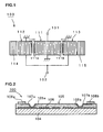
- FIG. 1 is a schematic plan view that shows the electrode structure of a boundary acoustic wave filter device according to an embodiment of the invention.
- FIG. 2 is a schematic front cross-sectional view of the boundary acoustic wave filter device.
- the boundary acoustic wave filter device 100 includes a piezoelectric body 104 and a dielectric body 105 laminated on the piezoelectric body 104.
- An electrode film 106 is formed between the piezoelectric body 104 and the dielectric body 105.
- the electrode film 106 forms the electrode structure shown in FIG. 1 . Therefore, the boundary acoustic wave filter device that utilizes a boundary acoustic wave propagating along a boundary between the piezoelectric body 104 and the dielectric body 105 is formed.
- the piezoelectric body 104 is formed of a monocrystal substrate made of 15 degrees rotated Y-cut X-propagating LiNbO 3 .
- the dielectric body 105 is made of SiO 2 .
- the electrode film 106 is formed in such a manner that a Au thin film having a thickness of 90 nm is deposited and patterned.
- the dielectric body 105 has a plurality of openings 105a and 105b.
- Conductive patterns 107a and 107b are formed in the openings 105a and 105b. Portions that are electrically connected to the outside of the electrode film 106 are exposed to the openings 105a and 105b.
- the conductive patterns 107a and 107b are electrically connected to the portions that are electrically connected to the outside of the electrode film 106.
- the conductive patterns 107a and 107b are provided so as to extend onto the upper surface of the dielectric body 105 and are electrically connected to external terminals 108a and 108b.
- the electrode film 106 forms the electrode structure shown in FIG. 1 . That is, a longitudinally coupled resonator boundary acoustic wave filter portion shown in the drawing is formed between an input terminal 101 and an output terminal 102.
- a first IDT 111 is arranged in the middle, and second and third IDTs 112 and 113 are arranged respectively on both sides of the IDT 111 in a boundary acoustic wave propagating direction in which a boundary acoustic wave propagates.
- reflectors 114 and 115 are arranged respectively on both sides of the region, in which the IDTs 111 to 113 are provided, in the boundary acoustic wave propagating direction.
- Narrow pitch electrode finger portions are provided in the IDTs 111 to 113, at portions at which two IDTs are located adjacent to each other.
- narrow pitch electrode finger portions 112A and 111A are provided at portions at which the IDT 112 and the IDT 111 are located adjacent to each other.
- the narrow pitch electrode finger portion is a portion of an end of the IDT, of which the interval of electrode fingers is smaller than the interval of electrode fingers of the other portion.
- a narrow pitch electrode finger portion 111B is provided in the IDT 111
- a narrow pitch electrode finger portion 113A is provided in the IDT 113.
- the narrow pitch electrode finger portions 111A, 111B, 112A and 113A are provided in the three-IDT type longitudinally coupled resonator boundary acoustic wave filter portion, whereby, an insertion loss is reduced in the longitudinally coupled resonator boundary acoustic wave filter portion that utilizes an inter-IDT resonance mode.
- the apodization weights are assigned in the IDTs 111 to 113, other than the narrow pitch electrode finger portions, so that portions located at ends of thus apodized portions adjacent to the narrow pitch electrode finger portions have a maximum electrode finger overlap width.
- apodization weights are assigned in the first IDT 111 so that the overlap width in the middle in the boundary acoustic wave propagating direction is minimal and portions having a maximum overlap width are located at ends of the weighted portion, adjacent to the second IDT 112 and to the third IDT 113.
- the shape surrounded by envelope is drum-shaped.
- a maximum-overlap width portion is located at an end of the weighted portion of the second IDT 112, adjacent to the first IDT 111, and the overlap width of the weighted portion at an end adjacent to the first reflector 114 is set to have a minimum overlap width. Then, the overlap width is sequentially reduced from the maximum overlap width to the minimum overlap width.
- a maximum overlap width portion of the weighted portion is located at an end adjacent to the first IDT 111
- a minimum overlap width portion of the weighted portion is located at an end adjacent to the second reflector 115. Then, the overlap width is sequentially reduced from the maximum overlap width portion to the minimum overlap width portion.
- the apodization weights are assigned so that, at portions at which the first IDT 111 and the second IDT 112 are located adjacent to each other, the overlap widths of electrode fingers located equidistantly from the middle between the first and second IDTs 111 and 112 are substantially equal.
- the apodization weights are assigned so that the overlap widths of electrode fingers of the first and third IDTs 111 and 113, located equidistantly from the middle between the first and third IDTs 111 and 113, are substantially equal.
- the boundary acoustic wave filter device 100 of the present embodiment having the electrode structure shown in FIG. 1 was manufactured in the following specifications.
- First IDT 111 The total number of electrode fingers including the narrow pitch electrode finger portions was 35, the overlap width of the minimum overlap width portion was 28 ⁇ m, and the overlap width of each maximum overlap width portion was 40 ⁇ m.
- Second and third IDTs 112 and 113 The total number of electrode fingers including the narrow pitch electrode finger portion was 19, the overlap width of the minimum overlap width portion was 28 ⁇ m, and the overlap width of the maximum overlap width portion was 40 ⁇ m.
- First and second reflectors 114 and 115 The number of electrode fingers was 25.
- the interval of electrode fingers, other than the narrow pitch electrode finger portions was 0.804 ⁇ m, and the interval of electrode fingers of each of the narrow pitch electrode finger portions 111A, 111B, 112A and 113A was 0.739 ⁇ m.
- the number of electrode fingers of each narrow pitch electrode finger portion was three.
- the interval of electrode fingers of each of the reflectors 114 and 115 was 0.797 ⁇ m.
- the overlap width of each of IDTs 611 to 613 was 40 ⁇ m.
- apodization weights are not assigned to the narrow pitch electrode finger portions 111A, 111B, 112A and 113A. That is, in each narrow pitch electrode finger portion, the overlap width is set to the maximum overlap width.
- FIG. 4 is a schematic plan view that shows the electrode structure of the existing boundary acoustic wave filter device prepared for comparison.
- the electrode structure shown in the drawing is formed between an input terminal 601 and an output terminal 602. That is, except that the above described apodization weights are not assigned, the electrode structure, which is similar to that of the boundary acoustic wave filter device 100, is formed.
- Second and third IDTs 612 and 613 are arranged respectively on both sides of a first IDT 611, and reflectors 614 and 615 are provided respectively on both sides of the portion, in which the IDTs 611 to 613 are provided, in the boundary acoustic wave propagating direction.
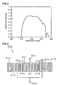
- FIG. 3 shows the filter characteristic of the longitudinally coupled resonator boundary acoustic wave filter device of the present embodiment manufactured as described above.
- FIG. 5 shows the filter characteristic of the boundary acoustic wave filter device of the comparative example.
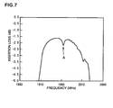
- FIG. 6 is a schematic plan view that shows the electrode structure of a longitudinally coupled resonator boundary acoustic wave filter device according to a second comparative example.
- FIG. 7 is a view that shows the filter characteristic of the boundary acoustic wave filter device according to the second comparative example.
- the boundary acoustic wave filter device 200 of the second comparative example is formed in a similar manner to the boundary acoustic wave filter device 100 except that apodization weights are assigned differently from the boundary acoustic wave filter device 100.
- apodization weights are assigned in the IDTs 211 to 213 so that the overlap width of electrode fingers located in the middle is maximal and the overlap width reduces toward an end of each IDT.
- Reflectors 214 and 215 are arranged on both sides of the portion in which the IDTs 211 to 213 are provided. The sizes of the maximum overlap width and minimum overlap width are equal to those of the boundary acoustic wave filter device 100. As shown in FIG. 7 , in the boundary acoustic wave filter device 200, as shown in FIG.
- apodization weights are assigned so that ends adjacent to the narrow pitch electrode finger portions have a maximum overlap width.
- the weights assigned in the adjacent IDTs are symmetrical with respect to the middle between the adjacent IDTs.
- the apodization weights of the IDT 111 are assigned so that the overlap width weights of the half of the IDT 111 adjacent to the IDT 112 and the overlap width weights of the IDT 112 are formed symmetrically with respect to the middle between the IDTs 111 and 112.
- the apodization weights of the half of the IDT 111 adjacent to the IDT 113 and the apodization weights of the IDT 113 are symmetrical with respect to the middle between the IDTs 111 and 113.
- the three-IDT type longitudinally coupled resonator boundary acoustic wave filter device is described; instead, it may be a five-IDT type longitudinally coupled resonator boundary acoustic wave filter device in which fourth and fifth IDTs are arranged respectively on both sides of the portion, in which the first to third IDTs are provided, in the boundary acoustic wave propagating direction.
- the first and second reflectors will be provided respectively on both sides of the portion, in which the first to fifth IDTs are provided, in the boundary acoustic wave propagating direction.
- the second and fourth IDTs and the third and fifth IDTs respectively have narrow pitch electrode finger portions at portions at which the second and fourth IDTs are located adjacent to each other and at portions at which the third and fifth IDTs are located adjacent to each other, the apodization weights are assigned in the fourth and fifth IDTs so that the electrode finger overlap width sequentially varies in the boundary acoustic wave propagating direction, and the apodization weights are assigned in the fourth and fifth IDTs, so that the electrode fingers located adjacent to the second and third IDTs have a maximum overlap width.
- the apodization weights are assigned so that the maximum overlap width portions of the second and third IDTs are located at ends adjacent to the fourth and fifth IDTs. That is, the apodization weights similar to the first IDT 111 shown in FIG. 1 are assigned in the second and third IDTs.
- the invention is not limited to the single three-IDT type longitudinally coupled resonator boundary acoustic wave filter device 100 shown in FIG. 1 .
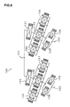
- the invention may also be applied to a boundary acoustic wave filter device that has a balance-unbalance converter function and that includes a plurality of three-IDT type longitudinally coupled resonator boundary acoustic wave filter devices connected to each other.
- the structures of IDTs are schematically shown by symbols that X is placed inside the rectangular portions.
- first to third IDTs have narrow pitch electrode finger portions and apodization weights are assigned as in the case of the first to third IDTs 111 to 113.
- the electrode structure shown in the drawing is connected between an unbalanced terminal 121 and first and second balanced terminals 122 and 123. That is, three three-IDT type longitudinally coupled resonator boundary acoustic wave filter portions 125 to 127 are connected to the unbalanced terminal 121 via a one-port boundary acoustic wave resonator 124.
- the longitudinally coupled resonator boundary acoustic wave filter portions 125 to 127 are three-IDT type longitudinally coupled resonator boundary acoustic wave filters that are formed similarly to the longitudinally coupled resonator boundary acoustic wave filter device 100.
- the longitudinally coupled resonator boundary acoustic wave filter portions 125 to 127 are connected to the first balanced terminal 122 via one-port boundary acoustic wave resonators 128 and 129 that are connected in parallel with each other.
- three three-IDT longitudinally coupled resonator boundary acoustic wave filter portions 132 to 134 are connected to the unbalanced terminal 121 via a one-port boundary acoustic wave resonator 131. Then, the three three-IDT type longitudinally coupled resonator boundary acoustic wave filter portions 132 to 134 are connected to the second balanced terminal 123 via one-port boundary acoustic wave resonators 135 and 136 that are connected in parallel with each other.
- phase of the first to third IDTs of each of the longitudinally coupled resonator boundary acoustic wave filter portions 132 to 134 and the phase of the first to third IDTs of each of the longitudinally coupled resonator boundary acoustic wave filter portions 125 to 127 are adjusted so that, when the unbalanced terminal 121 is used as an input terminal, the phase of an output signal extracted from the second balanced terminal 123 is different by 180 degrees from the phase of an output signal extracted from the first balanced terminal 122.
- the balance-unbalance converter function is implemented, and, in accordance with the invention, the narrow pitch electrode finger portions are provided at portions at which IDTs are located adjacent to each other and the apodization weights are assigned in the first to third IDTs as in the similar manner to the boundary acoustic wave filter device 100.
- the narrow pitch electrode finger portions are provided at portions at which IDTs are located adjacent to each other and the apodization weights are assigned in the first to third IDTs as in the similar manner to the boundary acoustic wave filter device 100.
- the piezoelectric body is not limited to LiNbO 3 .
- the piezoelectric body may employ various piezoelectric monocrystals or piezoelectric ceramics, such as LiTaO 3 or quartz.
- the dielectric body may be made of silicon oxide other than SiO 2 or other dielectric bodies such as SiN.
- the electrode material is not specifically limited.
- An electrode film that includes IDTs may be formed of a metal film by laminating a plurality of metal layers.
- application of the invention is not limited to the boundary acoustic wave filter device; the invention may also be applied to a surface acoustic wave filter device that is formed so that an electrode structure including IDTs are formed on the upper surface of the piezoelectric body.
- the transverse mode ripple tends to appear largely in the boundary acoustic wave filter device as compared with the surface acoustic wave filter device, so that the invention is more effective in the boundary acoustic wave filter device.
Claims (10)
- Akustische Wellenfiltervorrichtung (100), umfassend:einen piezoelektrischen Körper (104),eine erste IDT (111), die auf dem piezoelektrischen Körper (104) angeordnet ist, zweite und dritte IDTs (112, 113), die jeweils an beiden Seiten der ersten IDT (111) in einer akustischen Wellenausbreitungsrichtung, in der sich eine akustische Welle ausbreitet, angeordnet sind, und erste und zweite Reflektoren (114, 115), die jeweils an beiden Seiten des Bereichs, in dem die ersten bis dritten IDTs (111-113) in der akustischen Wellenausbreitungsrichtung vorgesehen sind, angeordnet sind, wobei Elektrodenfingerabschnitte (112A, 111A, 111B, 113A) mit engem Abstand in den ersten bis dritten IDTs (111-113) an Abschnitten vorgesehen sind, an denen zwei IDTs benachbart zueinander in der akustischen Wellenausbreitungsrichtung angeordnet sind, wobei jeder Elektrodenfingerabschnitt mit engem Abstand ein Abschnitt des Endes der jeweiligen IDT ist, von der das Intervall der Elektrodenfinger kleiner ist als das Intervall der Elektrodenfinger der anderen Abschnitte der jeweiligen IDT, wobeidie akustische Wellenfiltervorrichtung eine längsgekoppelte akustische Resonatorwellenfiltervorrichtung ist, dadurch gekennzeichnet, daßApodisationsgewichte in einem Abschnitt, der anders als der Elektrodenfingerabschnitt (112A, 111 A, 111 B, 113A) mit engem Abstand ist, in den ersten bis dritten IDTs (111-113), die die Elektrodenfingerabschnitte mit engem Abstand aufweisen, so zugeordnet sind, daß die Elektrodenfingerüberlappungsweite sequentiell in der akustischen Wellenausbreitungsrichtung variiert und Abschnitte, die an Enden angeordnet sind, die benachbart zu den Elektrodenfingerabschnitte mit engem Abstand sind, eine maximale Elektrodenfingerüberlappungsweite aufweisen.
- Akustische Wellenfiltervorrichtung (100) nach Anspruch 1, wobei die Apodisationsgewichte so zugeordnet sind, daß in der ersten IDT (111) die Überlappungsweite der ersten IDT in der Mitte in der akustischen Wellenausbreitungsrichtung minimal ist und maximale Überlappungsweitenabschnitte an Enden der ersten IDT, die die Apodisationsgewichte aufweisen, benachbart zur zweiten IDT (112) und benachbart zur dritten IDT (113) angeordnet sind, wodurch ein von einem einzelnen Paar von Umschlägen, das durch Apodisationsgewichte gebildet wird, umgebener Abschnitt eine taillierte Trommelform aufweist.
- Akustische Wellenfiltervorrichtung (100) nach Anspruch 1 oder 2, wobei die Apodisationsgewichte so zugeordnet sind, daß
ein maximaler Überlappungsweitenabschnitt an einem Ende des Abschnitts der zweiten IDT (112), das die Apodisationsgewichte aufweist, benachbart zur ersten IDT (111) angeordnet ist, ein minimaler Überlappungsweitenabschnitt an einem Ende des Abschnitts der zweiten IDT (112), das die Apodisationsgewichte aufweist, benachbart zum ersten Reflektor (114) angeordnet ist, und die Überlappungsweite sequentiell von der maximalen Überlappungsweite zur minimalen Überlappungsweite abnimmt, und
ein maximaler Überlappungsweitenabschnitt an einem Ende des Abschnitts der dritten IDT (113), das die Apodisationsgewichte aufweist, benachbart zur ersten IDT (111) angeordnet ist, ein minimaler Überlappungsweitenabschnitt an einem Ende des Abschnitts der dritten IDT (113), das die Apodisationsgewichte aufweist, benachbart zum zweiten Reflektor (115) angeordnet ist, und die Überlappungsweite sequentiell von dem maximalen Überlappungsweitenabschnitt zum minimalen Überlappungsweitenabschnitt abnimmt. - Akustische Wellenfiltervorrichtung (100) nach einem der Ansprüche 1 bis 3, wobei
an einem Abschnitt, an dem die ersten und zweiten IDTs (111, 112) benachbart zueinander angeordnet sind, die Apodisationsgewichte so zugeordnet sind, daß die Überlappungsweiten der Elektrodenfinger der entsprechenden ersten und zweiten IDTs (111, 112), die mit gleichem Abstand zur Mitte zwischen den ersten und zweiten IDTs (111, 112) angeordnet sind, im wesentlichen gleich sind, und wobei
an einem Abschnitt, an dem die ersten und dritten IDTs (111, 113) benachbart zueinander angeordnet sind, die Überlappungsweiten der Elektrodenfinger der entsprechenden ersten IDTs (111, 113), die im gleichen Abstand zur Mitte zwischen den ersten und dritten IDTs (111, 113) angeordnet sind, im wesentlichen gleich sind. - Akustische Wellenfiltervorrichtung nach Anspruch 1 oder 2, wobei vierte und fünfte IDTs jeweils auf beiden Seiten des Bereichs, in dem die ersten bis dritten IDTs (111-113) vorgesehen sind, in der akustischen Wellenausbreitungsrichtung angeordnet sind, und die ersten und zweiten Reflektoren (114, 115) jeweils auf beiden Seiten des Bereichs, in dem die ersten bis fünften IDTs vorgesehen sind, in der akustischen Wellenausbreitungsrichtung angeordnet sind.
- Akustische Wellenfiltervorrichtung nach Anspruch 5, wobei die Apodisationsgewichte in der zweiten IDT (112) so angeordnet sind, daß die Überlappungsweite der Mitte der zweiten IDT (112) in der akustischen Wellenausbreitungsausbreitungsrichtung minimal ist und maximale Überlappungsweitenabschnitte an Enden des Abschnitts der zweiten IDT (112), die die Apodisationsgewichte aufweisen, benachbart zur vierten IDT und benachbart zur ersten IDT (111) angeordnet sind, wodurch ein von einem einzelnen Paar von Umschlägen, das durch Apodisationsgewichte gebildet wird, umgebener Abschnitt eine taillierte Trommelform aufweist.
- Akustische Wellenfiltervorrichtung nach Anspruch 5 oder 6, wobei die Apodisationsgewichte in der dritten IDT (113) so angeordnet sind, daß die Überlappungsweite der Mitte der dritten IDT (113) in der akustischen Wellenausbreitungsausbreitungsrichtung minimal ist und maximale Überlappungsweitenabschnitte an Enden des Abschnitts der dritten IDT (113), die die Apodisationsgewichte aufweisen, benachbart zur ersten IDT (111) und benachbart zur fünften IDT angeordnet sind, wodurch ein von einem einzelnen Paar von Umschlägen, das durch Apodisationsgewichte gebildet wird, umgebener Abschnitt eine taillierte Trommelform aufweist.
- Akustische Wellenfiltervorrichtung nach einem der Ansprüche 5 bis 7, wobei die zweiten (112) und vierten IDTs jeweils Elektrodenfingerabschnitte mit engem Abstand an einem Abschnitt umfassen, an dem die zweite IDT und die vierte IDT benachbart zueinander angeordnet sind, die dritten (113) und fünften IDTs jeweils Elektrodenfingerabschnitte mit engem Abstand an einem Abschnitt umfassen, an dem die dritten und fünften IDTs benachbart zueinander angeordnet sind, Apodisationsgewichte in den vierten und fünften IDTs zugeordnet sind, die anders sind als die Elektrodenfingerabschnitte mit schmalem Abstand, so daß die Elektrodenfingerüberlappungsweite fortlaufend in der akustischen Wellenausbreitungsrichtung variiert und die Elektrodenfinger der Enden der Abschnitte der vierten und fünften IDTs, die die Apodisationsgewichte aufweisen, jeweils benachbart zu den zweiten und dritten IDTs (112, 113) sind, eine maximale Überlappungsweite aufweisen.
- Akustische Wellenfiltervorrichtung nach einem der Ansprüche 1 bis 8, ferner umfassend: eine dielektrische Körperschicht (105), die auf dem piezoelektrischen Körper (104) laminiert ist, wobei die akustische Grenzwelle als die akustische Welle verwendet wird.
- Akustische Wellenfiltervorrichtung nach einem der Ansprüche 1 bis 8, wobei eine akustische Oberflächenwelle als die akustische Welle verwendet wird.
Applications Claiming Priority (2)
| Application Number | Priority Date | Filing Date | Title |
|---|---|---|---|
| JP2006265610 | 2006-09-28 | ||
| PCT/JP2007/066305 WO2008038481A1 (fr) | 2006-09-28 | 2007-08-22 | Filtre d'onde acoustique |
Publications (3)
| Publication Number | Publication Date |
|---|---|
| EP2068444A1 EP2068444A1 (de) | 2009-06-10 |
| EP2068444A4 EP2068444A4 (de) | 2012-01-25 |
| EP2068444B1 true EP2068444B1 (de) | 2013-06-26 |
Family
ID=39229920
Family Applications (1)
| Application Number | Title | Priority Date | Filing Date |
|---|---|---|---|
| EP07792891.9A Active EP2068444B1 (de) | 2006-09-28 | 2007-08-22 | Oberflächenwellenfilter |
Country Status (6)
| Country | Link |
|---|---|
| US (1) | US7728699B2 (de) |
| EP (1) | EP2068444B1 (de) |
| JP (1) | JP4631972B2 (de) |
| KR (1) | KR101024189B1 (de) |
| CN (1) | CN101517894B (de) |
| WO (1) | WO2008038481A1 (de) |
Families Citing this family (14)
| Publication number | Priority date | Publication date | Assignee | Title |
|---|---|---|---|---|
| WO2008056697A1 (fr) * | 2006-11-08 | 2008-05-15 | Panasonic Corporation | Résonateur d'onde acoustique de surface |
| TWI393340B (zh) * | 2009-02-13 | 2013-04-11 | 中原大學 | 球形旋轉式壓電馬達 |
| CN102405596B (zh) * | 2009-04-23 | 2014-07-30 | 松下电器产业株式会社 | 天线共用器 |
| JP4900420B2 (ja) * | 2009-05-27 | 2012-03-21 | 株式会社村田製作所 | 弾性波装置 |
| CN104467729B (zh) * | 2009-11-02 | 2018-08-03 | 天工滤波方案日本有限公司 | 弹性波元件、和其使用的双工器及电子设备 |
| JP2011135244A (ja) * | 2009-12-24 | 2011-07-07 | Panasonic Corp | 弾性波デバイス及びこれを用いたフィルタ、デュプレクサ |
| DE102010034121A1 (de) | 2010-08-12 | 2012-02-16 | Epcos Ag | Mit akustischen Wellen arbeitendes Bauelement mit reduziertem Temperaturgang der Frequenzlage und Verfahren zur Herstellung |
| JP2013229641A (ja) * | 2010-08-27 | 2013-11-07 | Murata Mfg Co Ltd | 弾性波フィルタ |
| JP2015073207A (ja) * | 2013-10-03 | 2015-04-16 | スカイワークス・パナソニック フィルターソリューションズ ジャパン株式会社 | 弾性波共振器 |
| WO2015182522A1 (ja) | 2014-05-26 | 2015-12-03 | 株式会社村田製作所 | 弾性波装置 |
| CN104677518B (zh) * | 2015-02-05 | 2018-02-13 | 中国科学院微电子研究所 | 声表面波温度传感器 |
| WO2018123657A1 (ja) | 2016-12-28 | 2018-07-05 | 株式会社村田製作所 | 縦結合共振子型弾性波フィルタ |
| JP7231007B2 (ja) * | 2019-03-06 | 2023-03-01 | 株式会社村田製作所 | フィルタ、マルチプレクサ、高周波フロントエンド回路及び通信装置 |
| CN116633307A (zh) * | 2023-05-23 | 2023-08-22 | 无锡市好达电子股份有限公司 | 弹性波装置 |
Family Cites Families (13)
| Publication number | Priority date | Publication date | Assignee | Title |
|---|---|---|---|---|
| JPS5330848A (en) * | 1976-09-03 | 1978-03-23 | Murata Manufacturing Co | Surface acoustic wave device |
| JPS596612A (ja) * | 1982-07-05 | 1984-01-13 | Hitachi Ltd | 弾性表面波装置 |
| JPH05121997A (ja) * | 1991-10-30 | 1993-05-18 | Sanyo Electric Co Ltd | 弾性表面波フイルタ |
| JP3075124B2 (ja) * | 1995-03-08 | 2000-08-07 | 株式会社村田製作所 | 表面波共振子 |
| US5635883A (en) * | 1995-08-28 | 1997-06-03 | Motorola, Inc. | Acoustic wave filter with filter-shaping element and method |
| JPH09205342A (ja) * | 1996-01-26 | 1997-08-05 | Matsushita Electric Ind Co Ltd | 弾性表面波フィルタ |
| JPH09214281A (ja) * | 1996-01-31 | 1997-08-15 | Mitsumi Electric Co Ltd | 弾性表面波フィルタ |
| JPH10261936A (ja) | 1997-03-19 | 1998-09-29 | Mitsubishi Electric Corp | 弾性表面波フィルタ |
| EP1249934B1 (de) * | 2001-04-09 | 2013-07-31 | Murata Manufacturing Co., Ltd. | Akustische Oberflächenwellenanordnung und Kommunikationseinheit |
| JP4049034B2 (ja) * | 2002-08-22 | 2008-02-20 | 株式会社村田製作所 | 弾性表面波フィルタ、通信装置 |
| CN100452650C (zh) * | 2003-07-02 | 2009-01-14 | 京瓷株式会社 | 弹性表面波装置及使用该装置的通信装置 |
| JP4480490B2 (ja) * | 2003-07-02 | 2010-06-16 | 京セラ株式会社 | 弾性表面波装置およびそれを用いた通信装置 |
| KR100680512B1 (ko) * | 2004-08-23 | 2007-02-08 | 가부시키가이샤 무라타 세이사쿠쇼 | 밸런스형 탄성 표면파 필터 |
-
2007
- 2007-08-22 KR KR1020087030112A patent/KR101024189B1/ko active IP Right Grant
- 2007-08-22 JP JP2008536305A patent/JP4631972B2/ja active Active
- 2007-08-22 EP EP07792891.9A patent/EP2068444B1/de active Active
- 2007-08-22 WO PCT/JP2007/066305 patent/WO2008038481A1/ja active Application Filing
- 2007-08-22 CN CN2007800354536A patent/CN101517894B/zh active Active
-
2009
- 2009-01-26 US US12/359,424 patent/US7728699B2/en active Active
Also Published As
| Publication number | Publication date |
|---|---|
| JPWO2008038481A1 (ja) | 2010-01-28 |
| KR20090026280A (ko) | 2009-03-12 |
| EP2068444A1 (de) | 2009-06-10 |
| KR101024189B1 (ko) | 2011-03-22 |
| US7728699B2 (en) | 2010-06-01 |
| CN101517894A (zh) | 2009-08-26 |
| US20090121810A1 (en) | 2009-05-14 |
| WO2008038481A1 (fr) | 2008-04-03 |
| CN101517894B (zh) | 2011-12-28 |
| JP4631972B2 (ja) | 2011-02-16 |
| EP2068444A4 (de) | 2012-01-25 |
Similar Documents
| Publication | Publication Date | Title |
|---|---|---|
| EP2068444B1 (de) | Oberflächenwellenfilter | |
| EP2128982B1 (de) | Elastikwellenanordnung | |
| EP1998443B1 (de) | Resonator für akustisch-mechanische schwingungen | |
| US5874868A (en) | Longitudinally coupled surface acoustic wave resonator filter having different distances between transducers | |
| US20200067489A1 (en) | Acoustic wave filter device, multiplexer and composite filter device | |
| US7804384B2 (en) | Acoustic wave filter device utilizing filters having different acoustic wave propagation directions | |
| US7479855B2 (en) | Longitudinally-coupled-resonator-type elastic wave filter device | |
| US7532090B2 (en) | Acoustic wave filter device and duplexer | |
| EP1830467B1 (de) | Akustisches oberflächenwellenfiltergerät | |
| EP2963818B1 (de) | Oberflächenschallwellenresonator | |
| WO2000076067A1 (fr) | Filtre a ondes de surface | |
| JP5083469B2 (ja) | 弾性表面波装置 | |
| US8525621B2 (en) | Boundary acoustic wave filter | |
| US5666091A (en) | Structure of surface acoustic wave filter | |
| JP2018182460A (ja) | 弾性波共振器、フィルタおよびマルチプレクサ | |
| US5294859A (en) | Surface acoustic wave filter device | |
| US7394336B2 (en) | Elastic boundary wave apparatus | |
| EP0782256B1 (de) | Akustisches Oberflächenwellenresonatorfilter | |
| EP2256925B1 (de) | Elastische Wellenvorrichtung | |
| EP1420514B1 (de) | Oberflächenwellenbauelement | |
| JP4548305B2 (ja) | 二重モード弾性表面波フィルタ | |
| JPH10335973A (ja) | 縦結合二重モードsawフィルタ | |
| JPH08204501A (ja) | 弾性表面波フィルタ | |
| JP2008017249A (ja) | 弾性表面波素子片および弾性表面波デバイス |
Legal Events
| Date | Code | Title | Description |
|---|---|---|---|
| PUAI | Public reference made under article 153(3) epc to a published international application that has entered the european phase |
Free format text: ORIGINAL CODE: 0009012 |
|
| 17P | Request for examination filed |
Effective date: 20090216 |
|
| AK | Designated contracting states |
Kind code of ref document: A1 Designated state(s): AT BE BG CH CY CZ DE DK EE ES FI FR GB GR HU IE IS IT LI LT LU LV MC MT NL PL PT RO SE SI SK TR |
|
| AX | Request for extension of the european patent |
Extension state: AL BA HR MK RS |
|
| A4 | Supplementary search report drawn up and despatched |
Effective date: 20111227 |
|
| RIC1 | Information provided on ipc code assigned before grant |
Ipc: H03H 9/64 20060101AFI20111220BHEP Ipc: H03H 9/145 20060101ALI20111220BHEP Ipc: H01L 41/09 20060101ALI20111220BHEP |
|
| DAX | Request for extension of the european patent (deleted) | ||
| GRAP | Despatch of communication of intention to grant a patent |
Free format text: ORIGINAL CODE: EPIDOSNIGR1 |
|
| GRAP | Despatch of communication of intention to grant a patent |
Free format text: ORIGINAL CODE: EPIDOSNIGR1 |
|
| GRAS | Grant fee paid |
Free format text: ORIGINAL CODE: EPIDOSNIGR3 |
|
| GRAA | (expected) grant |
Free format text: ORIGINAL CODE: 0009210 |
|
| AK | Designated contracting states |
Kind code of ref document: B1 Designated state(s): AT BE BG CH CY CZ DE DK EE ES FI FR GB GR HU IE IS IT LI LT LU LV MC MT NL PL PT RO SE SI SK TR |
|
| REG | Reference to a national code |
Ref country code: GB Ref legal event code: FG4D |
|
| REG | Reference to a national code |
Ref country code: CH Ref legal event code: EP |
|
| REG | Reference to a national code |
Ref country code: AT Ref legal event code: REF Ref document number: 619069 Country of ref document: AT Kind code of ref document: T Effective date: 20130715 |
|
| REG | Reference to a national code |
Ref country code: IE Ref legal event code: FG4D |
|
| REG | Reference to a national code |
Ref country code: DE Ref legal event code: R096 Ref document number: 602007031290 Country of ref document: DE Effective date: 20130822 |
|
| PG25 | Lapsed in a contracting state [announced via postgrant information from national office to epo] |
Ref country code: SE Free format text: LAPSE BECAUSE OF FAILURE TO SUBMIT A TRANSLATION OF THE DESCRIPTION OR TO PAY THE FEE WITHIN THE PRESCRIBED TIME-LIMIT Effective date: 20130626 Ref country code: FI Free format text: LAPSE BECAUSE OF FAILURE TO SUBMIT A TRANSLATION OF THE DESCRIPTION OR TO PAY THE FEE WITHIN THE PRESCRIBED TIME-LIMIT Effective date: 20130626 Ref country code: GR Free format text: LAPSE BECAUSE OF FAILURE TO SUBMIT A TRANSLATION OF THE DESCRIPTION OR TO PAY THE FEE WITHIN THE PRESCRIBED TIME-LIMIT Effective date: 20130927 Ref country code: LT Free format text: LAPSE BECAUSE OF FAILURE TO SUBMIT A TRANSLATION OF THE DESCRIPTION OR TO PAY THE FEE WITHIN THE PRESCRIBED TIME-LIMIT Effective date: 20130626 Ref country code: SI Free format text: LAPSE BECAUSE OF FAILURE TO SUBMIT A TRANSLATION OF THE DESCRIPTION OR TO PAY THE FEE WITHIN THE PRESCRIBED TIME-LIMIT Effective date: 20130626 |
|
| REG | Reference to a national code |
Ref country code: AT Ref legal event code: MK05 Ref document number: 619069 Country of ref document: AT Kind code of ref document: T Effective date: 20130626 |
|
| REG | Reference to a national code |
Ref country code: LT Ref legal event code: MG4D |
|
| PG25 | Lapsed in a contracting state [announced via postgrant information from national office to epo] |
Ref country code: BG Free format text: LAPSE BECAUSE OF FAILURE TO SUBMIT A TRANSLATION OF THE DESCRIPTION OR TO PAY THE FEE WITHIN THE PRESCRIBED TIME-LIMIT Effective date: 20130926 |
|
| REG | Reference to a national code |
Ref country code: NL Ref legal event code: VDEP Effective date: 20130626 |
|
| PG25 | Lapsed in a contracting state [announced via postgrant information from national office to epo] |
Ref country code: LV Free format text: LAPSE BECAUSE OF FAILURE TO SUBMIT A TRANSLATION OF THE DESCRIPTION OR TO PAY THE FEE WITHIN THE PRESCRIBED TIME-LIMIT Effective date: 20130626 |
|
| PG25 | Lapsed in a contracting state [announced via postgrant information from national office to epo] |
Ref country code: EE Free format text: LAPSE BECAUSE OF FAILURE TO SUBMIT A TRANSLATION OF THE DESCRIPTION OR TO PAY THE FEE WITHIN THE PRESCRIBED TIME-LIMIT Effective date: 20130626 Ref country code: PT Free format text: LAPSE BECAUSE OF FAILURE TO SUBMIT A TRANSLATION OF THE DESCRIPTION OR TO PAY THE FEE WITHIN THE PRESCRIBED TIME-LIMIT Effective date: 20131028 Ref country code: IS Free format text: LAPSE BECAUSE OF FAILURE TO SUBMIT A TRANSLATION OF THE DESCRIPTION OR TO PAY THE FEE WITHIN THE PRESCRIBED TIME-LIMIT Effective date: 20131026 Ref country code: CZ Free format text: LAPSE BECAUSE OF FAILURE TO SUBMIT A TRANSLATION OF THE DESCRIPTION OR TO PAY THE FEE WITHIN THE PRESCRIBED TIME-LIMIT Effective date: 20130626 Ref country code: BE Free format text: LAPSE BECAUSE OF FAILURE TO SUBMIT A TRANSLATION OF THE DESCRIPTION OR TO PAY THE FEE WITHIN THE PRESCRIBED TIME-LIMIT Effective date: 20130626 Ref country code: AT Free format text: LAPSE BECAUSE OF FAILURE TO SUBMIT A TRANSLATION OF THE DESCRIPTION OR TO PAY THE FEE WITHIN THE PRESCRIBED TIME-LIMIT Effective date: 20130626 Ref country code: SK Free format text: LAPSE BECAUSE OF FAILURE TO SUBMIT A TRANSLATION OF THE DESCRIPTION OR TO PAY THE FEE WITHIN THE PRESCRIBED TIME-LIMIT Effective date: 20130626 Ref country code: CY Free format text: LAPSE BECAUSE OF FAILURE TO SUBMIT A TRANSLATION OF THE DESCRIPTION OR TO PAY THE FEE WITHIN THE PRESCRIBED TIME-LIMIT Effective date: 20130731 |
|
| PG25 | Lapsed in a contracting state [announced via postgrant information from national office to epo] |
Ref country code: NL Free format text: LAPSE BECAUSE OF FAILURE TO SUBMIT A TRANSLATION OF THE DESCRIPTION OR TO PAY THE FEE WITHIN THE PRESCRIBED TIME-LIMIT Effective date: 20130626 Ref country code: PL Free format text: LAPSE BECAUSE OF FAILURE TO SUBMIT A TRANSLATION OF THE DESCRIPTION OR TO PAY THE FEE WITHIN THE PRESCRIBED TIME-LIMIT Effective date: 20130626 Ref country code: RO Free format text: LAPSE BECAUSE OF FAILURE TO SUBMIT A TRANSLATION OF THE DESCRIPTION OR TO PAY THE FEE WITHIN THE PRESCRIBED TIME-LIMIT Effective date: 20130626 Ref country code: ES Free format text: LAPSE BECAUSE OF FAILURE TO SUBMIT A TRANSLATION OF THE DESCRIPTION OR TO PAY THE FEE WITHIN THE PRESCRIBED TIME-LIMIT Effective date: 20131007 |
|
| PG25 | Lapsed in a contracting state [announced via postgrant information from national office to epo] |
Ref country code: CY Free format text: LAPSE BECAUSE OF FAILURE TO SUBMIT A TRANSLATION OF THE DESCRIPTION OR TO PAY THE FEE WITHIN THE PRESCRIBED TIME-LIMIT Effective date: 20130626 |
|
| REG | Reference to a national code |
Ref country code: CH Ref legal event code: PL |
|
| PG25 | Lapsed in a contracting state [announced via postgrant information from national office to epo] |
Ref country code: DK Free format text: LAPSE BECAUSE OF FAILURE TO SUBMIT A TRANSLATION OF THE DESCRIPTION OR TO PAY THE FEE WITHIN THE PRESCRIBED TIME-LIMIT Effective date: 20130626 Ref country code: CH Free format text: LAPSE BECAUSE OF NON-PAYMENT OF DUE FEES Effective date: 20130831 Ref country code: LI Free format text: LAPSE BECAUSE OF NON-PAYMENT OF DUE FEES Effective date: 20130831 Ref country code: MC Free format text: LAPSE BECAUSE OF FAILURE TO SUBMIT A TRANSLATION OF THE DESCRIPTION OR TO PAY THE FEE WITHIN THE PRESCRIBED TIME-LIMIT Effective date: 20130626 |
|
| PLBE | No opposition filed within time limit |
Free format text: ORIGINAL CODE: 0009261 |
|
| STAA | Information on the status of an ep patent application or granted ep patent |
Free format text: STATUS: NO OPPOSITION FILED WITHIN TIME LIMIT |
|
| REG | Reference to a national code |
Ref country code: IE Ref legal event code: MM4A |
|
| REG | Reference to a national code |
Ref country code: FR Ref legal event code: ST Effective date: 20140430 |
|
| GBPC | Gb: european patent ceased through non-payment of renewal fee |
Effective date: 20130926 |
|
| PG25 | Lapsed in a contracting state [announced via postgrant information from national office to epo] |
Ref country code: IT Free format text: LAPSE BECAUSE OF FAILURE TO SUBMIT A TRANSLATION OF THE DESCRIPTION OR TO PAY THE FEE WITHIN THE PRESCRIBED TIME-LIMIT Effective date: 20130626 |
|
| 26N | No opposition filed |
Effective date: 20140327 |
|
| REG | Reference to a national code |
Ref country code: DE Ref legal event code: R097 Ref document number: 602007031290 Country of ref document: DE Effective date: 20140327 |
|
| PG25 | Lapsed in a contracting state [announced via postgrant information from national office to epo] |
Ref country code: IE Free format text: LAPSE BECAUSE OF NON-PAYMENT OF DUE FEES Effective date: 20130822 Ref country code: GB Free format text: LAPSE BECAUSE OF NON-PAYMENT OF DUE FEES Effective date: 20130926 |
|
| PG25 | Lapsed in a contracting state [announced via postgrant information from national office to epo] |
Ref country code: FR Free format text: LAPSE BECAUSE OF NON-PAYMENT OF DUE FEES Effective date: 20130902 |
|
| PG25 | Lapsed in a contracting state [announced via postgrant information from national office to epo] |
Ref country code: TR Free format text: LAPSE BECAUSE OF FAILURE TO SUBMIT A TRANSLATION OF THE DESCRIPTION OR TO PAY THE FEE WITHIN THE PRESCRIBED TIME-LIMIT Effective date: 20130626 Ref country code: MT Free format text: LAPSE BECAUSE OF FAILURE TO SUBMIT A TRANSLATION OF THE DESCRIPTION OR TO PAY THE FEE WITHIN THE PRESCRIBED TIME-LIMIT Effective date: 20130626 |
|
| PG25 | Lapsed in a contracting state [announced via postgrant information from national office to epo] |
Ref country code: LU Free format text: LAPSE BECAUSE OF NON-PAYMENT OF DUE FEES Effective date: 20130822 Ref country code: HU Free format text: LAPSE BECAUSE OF FAILURE TO SUBMIT A TRANSLATION OF THE DESCRIPTION OR TO PAY THE FEE WITHIN THE PRESCRIBED TIME-LIMIT; INVALID AB INITIO Effective date: 20070822 |
|
| REG | Reference to a national code |
Ref country code: DE Ref legal event code: R082 Ref document number: 602007031290 Country of ref document: DE Representative=s name: CBDL PATENTANWAELTE GBR, DE |
|
| PGFP | Annual fee paid to national office [announced via postgrant information from national office to epo] |
Ref country code: DE Payment date: 20230821 Year of fee payment: 17 |