EP2064465B1 - Getriebevorrichtung - Google Patents
Getriebevorrichtung Download PDFInfo
- Publication number
- EP2064465B1 EP2064465B1 EP07788409A EP07788409A EP2064465B1 EP 2064465 B1 EP2064465 B1 EP 2064465B1 EP 07788409 A EP07788409 A EP 07788409A EP 07788409 A EP07788409 A EP 07788409A EP 2064465 B1 EP2064465 B1 EP 2064465B1
- Authority
- EP
- European Patent Office
- Prior art keywords
- damping element
- transmission device
- transmission
- gear
- axial
- Prior art date
- Legal status (The legal status is an assumption and is not a legal conclusion. Google has not performed a legal analysis and makes no representation as to the accuracy of the status listed.)
- Not-in-force
Links
- 230000005540 biological transmission Effects 0.000 title claims abstract description 49
- 238000013016 damping Methods 0.000 claims abstract description 69
- 238000011161 development Methods 0.000 description 3
- 230000018109 developmental process Effects 0.000 description 3
- 230000008878 coupling Effects 0.000 description 1
- 238000010168 coupling process Methods 0.000 description 1
- 238000005859 coupling reaction Methods 0.000 description 1
- 230000003292 diminished effect Effects 0.000 description 1
- 239000000463 material Substances 0.000 description 1
- 230000035939 shock Effects 0.000 description 1
Images

Classifications
-
- F—MECHANICAL ENGINEERING; LIGHTING; HEATING; WEAPONS; BLASTING
- F16—ENGINEERING ELEMENTS AND UNITS; GENERAL MEASURES FOR PRODUCING AND MAINTAINING EFFECTIVE FUNCTIONING OF MACHINES OR INSTALLATIONS; THERMAL INSULATION IN GENERAL
- F16H—GEARING
- F16H55/00—Elements with teeth or friction surfaces for conveying motion; Worms, pulleys or sheaves for gearing mechanisms
- F16H55/02—Toothed members; Worms
- F16H55/14—Construction providing resilience or vibration-damping
-
- Y—GENERAL TAGGING OF NEW TECHNOLOGICAL DEVELOPMENTS; GENERAL TAGGING OF CROSS-SECTIONAL TECHNOLOGIES SPANNING OVER SEVERAL SECTIONS OF THE IPC; TECHNICAL SUBJECTS COVERED BY FORMER USPC CROSS-REFERENCE ART COLLECTIONS [XRACs] AND DIGESTS
- Y10—TECHNICAL SUBJECTS COVERED BY FORMER USPC
- Y10T—TECHNICAL SUBJECTS COVERED BY FORMER US CLASSIFICATION
- Y10T74/00—Machine element or mechanism
- Y10T74/19—Gearing
- Y10T74/19623—Backlash take-up
-
- Y—GENERAL TAGGING OF NEW TECHNOLOGICAL DEVELOPMENTS; GENERAL TAGGING OF CROSS-SECTIONAL TECHNOLOGIES SPANNING OVER SEVERAL SECTIONS OF THE IPC; TECHNICAL SUBJECTS COVERED BY FORMER USPC CROSS-REFERENCE ART COLLECTIONS [XRACs] AND DIGESTS
- Y10—TECHNICAL SUBJECTS COVERED BY FORMER USPC
- Y10T—TECHNICAL SUBJECTS COVERED BY FORMER US CLASSIFICATION
- Y10T74/00—Machine element or mechanism
- Y10T74/19—Gearing
- Y10T74/19633—Yieldability in gear trains
-
- Y—GENERAL TAGGING OF NEW TECHNOLOGICAL DEVELOPMENTS; GENERAL TAGGING OF CROSS-SECTIONAL TECHNOLOGIES SPANNING OVER SEVERAL SECTIONS OF THE IPC; TECHNICAL SUBJECTS COVERED BY FORMER USPC CROSS-REFERENCE ART COLLECTIONS [XRACs] AND DIGESTS
- Y10—TECHNICAL SUBJECTS COVERED BY FORMER USPC
- Y10T—TECHNICAL SUBJECTS COVERED BY FORMER US CLASSIFICATION
- Y10T74/00—Machine element or mechanism
- Y10T74/19—Gearing
- Y10T74/1987—Rotary bodies
- Y10T74/19893—Sectional
- Y10T74/19898—Backlash take-up
Definitions
- the invention relates to a transmission device according to the preamble of claim 1.
- Such transmission devices are used in particular in adjusting devices in motor vehicles such as power windows or sliding roofs, which are operated by means of an electric motor.
- an electric motor is used in particular, which adjusts via a transmission, for example, the window between an open and closed end position. Since vibrations and / or undesired impact loads can occur during actuation when starting the electric motor or when striking an end position, it is known to arrange damping elements between two axially adjacent gears.
- a transmission device is known in the art DE 102 46 711 A1 described. In the known transmission device is transmitted from a spur gear, a force in the circumferential direction by means of the damping elements on a Mit hesitationrad.
- a gear which consists of a hub body and a radially spaced sprocket body, which are interconnected via a deformable damping element.
- the damping element is claimed during operation of the gear on torsion.
- the second gear body with the hub body connecting damping element is loaded during operation of the gear on torsion
- the invention has the object to provide a transmission device with two axially juxtaposed gears, between which at least one damping element is arranged, wherein in the case of damping, an axial disengagement of the gears is prevented.
- the invention is based on the idea to arrange the at least one damping element such that it is not subjected to pressure during operation of the transmission device (output device), but rather, preferably exclusively, in the circumferential direction to train.
- the damping element is not compressed and thus can not be in the axial Widen direction.
- the damping element is stretched under tensile load and thereby even diminished in the axial direction.
- there is no force acting in the axial direction which tends to force the two gears apart.
- the damping elements are not loaded on torsion, which significantly increases their life.
- Both gears each have at least one axial extension, wherein the two extensions engage in a common corresponding opening, in particular an axial passage opening, of the damping element.
- damping elements are arranged distributed uniformly in the circumferential direction.
- both gears are positively connected in the axial direction with the damping element, so that forces can be transmitted in the circumferential direction .
- the positive connection or the form-fitting connection producing sections between the gear and the damping element must not be zwangsläüfig form congruent, which would be advantageous.
- One possibility for realizing an axial positive locking, which enables a transmission of force in the circumferential direction, is to provide on each of the two gear wheels at least one extension pointing in the axial direction, which engages in a corresponding opening in the damping element. If one of the gear wheels is driven, the extension engages an inner wall of the opening and thus transmits a force to the damping element, which in turn transmits a force to the axially adjacent gear wheel in the circumferential direction. Furthermore, it is conceivable that the extensions of the spaced gears in Circumferentially spaced openings, preferably through openings of the damping element, engage.
- Rubber and / or plastic elements are preferably used as damping elements.
- the damping element has two circumferentially spaced passage openings.
- Each gear engages with one extension in each opening.
- the extensions of one gear wheel clasp the extensions of the other gear, wherein in each case a radial gap is provided between two extensions within a passage opening. If one of the gears is rotated, then the damping element is stretched in the circumferential direction and a torque is transmitted via the damping element to the axially opposite gear.
- an axial projection on at least one of the gear wheels, which engages in a corresponding opening of the damping element
- an axial projection in particular of non-damping material, can be provided on the damping element, which engages in a corresponding opening of at least one gear wheel.
- Axial extensions are preferably provided on both axially opposite sides of the damping element, with which engages the damping element in corresponding openings in the two gear wheels.
- one of the gears is designed as a spur gear with an external toothing and the axially adjacent gear as a driver.
- Such trained transmission devices are suitable especially for use in adjusting devices in motor vehicles.
- the driver has an external toothing or other positive locking means on which, for example, a cable drum of the adjusting device can be plugged.
- the driver is attachable to the spur gear in the axial direction, wherein in the Aufsteckvorgang the damping element is received between the two gear wheels.
- the damping elements are preferably separate components, ie not a mass that bonds the gears. As a result, they can be disassembled, so replace, without destroying the transmission device.
- the damping elements are received in pockets of at least one gear, wherein two circumferentially adjacent pockets are separated by at least one radial web.
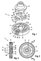
- the transmission device 1 shown in the figures comprises a first gear formed as a spur gear 2 and an axially adjacent, designed as a driver second gear 3. Between the first gear 2 and the second gear 3 three offset by 120 ° circumferentially arranged damping elements 4 are provided , The damping elements 4 are used for damping in the circumferential direction and for torque transmission between the two gears 2, 3. During operation of the transmission device, the damping elements 4 are loaded by the gears 2, 3 in the circumferential direction exclusively to train.
- the trained as a spur gear first gear 2 is provided with an external toothing 5 and with a coaxially thereto arranged inner hub 6 with a central through hole 7 for supporting the transmission device 1 on a bearing pin, not shown.
- Each damping element 4 is slightly curved and has circumferentially directed rounded ends 10, 11. Within each damping element 4 are two circumferentially spaced, elongated, formed as through holes openings 12, 13 are provided. Each opening 12, 13 receives in each case an axial extension 14, 15 of the first gear, wherein the two axial extensions 14, 15 of the first gear 2 to the adjacent, inner, mutually facing portions 16, 17 of the openings 12, 13 abut. The two axial extensions 14, 15 are separated from each other by a radial web 18 of the damping element 4. In each opening 12, 13 of the damping element 4 is in addition to an axial extension 14, 15 of the first gear 2, an axial extension 19, 20 of the second gear 3 was added.
- These extensions 19, 20 are arranged in the circumferentially outer, facing away from each other regions 21, 22 of the openings 12, 13, wherein, as in particular from Fig. 3 it can be seen between the two adjacent axial extensions 14, 19 and 15, 20 within each opening 12, 13 each have a radial gap 23, 24 is formed, which allows an extension of the damping element 4 regardless of the direction of rotation in the circumferential direction. If an overstretching of the damping element 4 or even a tearing of an opening 12, 13, ensures the clinging arrangement of the axial extensions 19, 20; 14, 15, that depending on the direction of rotation, either the axial extensions 14, 19 or 15, 20 abut each other and thus ensure further rotation of the transmission device 1.
- the damping elements are loaded exclusively on train.
- a compressive load and a torsional load are eliminated with advantage.
Landscapes
- Engineering & Computer Science (AREA)
- General Engineering & Computer Science (AREA)
- Mechanical Engineering (AREA)
- Gear Transmission (AREA)
- Gears, Cams (AREA)
- Steering Control In Accordance With Driving Conditions (AREA)
- Power Steering Mechanism (AREA)
- Valve Device For Special Equipments (AREA)
Description
- Die Erfindung betrifft eine Getriebevorrichtung gemäß dem Oberbegriff des Anspruches 1.
- Derartige Getriebevorrichtungen werden insbesondere in Verstelleinrichtungen in Kraftfahrzeugen wie elektrischen Fensterhebern oder Schiebedächern, welche mittels eines Elektromotors betrieben werden, eingesetzt. Hierbei wird insbesondere ein Elektromotor verwendet, welcher über ein Getriebe, z.B. das Fenster zwischen einer Öffnungs- und Schließ-Endstellung verstellt. Da es bei der Betätigung beim Anlaufen des Elektromotors oder beim Anschlagen an einer Endstellung zu Schwingungen und/oder unerwünschten Stoßbelastungen kommen kann, ist es bekannt, zwischen zwei axial benachbarten Getrieberädern Dämpfungselemente anzuordnen. Eine solche Getriebevorrichtung ist als Stand der Technik in der
DE 102 46 711 A1 beschrieben. Bei der bekannten Getriebevorrichtung wird von einem Stirnrad eine Kraft in Umfangsrichtung mittels der Dämpfungselemente auf ein Mitnehmerrad übertragen. Beim Anschlagen an eine Endstellung oder bei Stoßbelastungen werden die Dämpfungselemente in Umfangsrichtung gestaucht, wodurch sich diese in axialer Richtung aufweiten. Hierdurch werden die beiden Getrieberäder auseinandergedrückt, was eine hohe mechanische Belastung für die Bauteile, insbesondere für die Lager, mit sich bringt. - Aus der unveröffentlichten
DE 10 2006 014 763 ist ein Getrieberad bekannt, welches aus einem Nabenkörper und einem radial beabstandeten Zahnkranzkörper besteht, die über ein verformbares Dämpfungselement miteinander verbunden sind. Das Dämpfungselement wird beim Betrieb des Zahnrades auf Torsion beansprucht. Weiterhin ist aus der Druckschrift bekannt, an dem Nabenkörper einen zweiten, axial zu dem ersten Zahnradkörper beabstandeten zweiten Zahnradkörper über ein Dämpfungselement zu befestigen, wobei der zweite Zahnradkörper ebenfalls radial beabstandet zu dem Nabenkörper angeordnet ist. Auch das dem zweiten Zahnradkörper mit dem Nabenkörper verbindende Dämpfungselement wird beim Betrieb des Zahnrades auf Torsion belastet - Mit der gattungsbildenden
US-A-5 214 975 ist eine Kupplungsvorrichtung bekannt geworden, bei der axiale Fortsätze zweier unterschiedlicher Getrieberäder in ein ringförmiges Dämpfelement eingreifen. Dabei ist jeder axiale Fortsatz in einer eigenen separaten axialen Öffnung im Dämpfring angeordnet. Das Dämpfelement wird auf Druck und auf Zug belastet. - Der Erfindung liegt die Aufgabe zugrunde, eine Getriebevorrichtung mit zwei axial nebeneinander angeordneten Getrieberädern vorzuschlagen, zwischen denen mindestens ein Dämpfungselement angeordnet ist, wobei im Dämpfungsfall ein axiales Auseinanderdrücken der Getrieberäder verhindert wird.
- Diese Aufgabe wird mit den Merkmalen des Anspruches 1 gelöst.
- Vorteilhafte Weiterbildungen der Erfindung sind in den Unteransprüchen angegeben.
- Der Erfindung liegt der Gedanke zugrunde, das mindestens eine Dämpfungselement derart anzuordnen, dass dieses beim Betrieb der Getriebevorrichtung (Abtriebsvorrichtung) nicht auf Druck, sondern, vorzugsweise ausschließlich, in Umfangsrichtung auf Zug belastet wird. Hierdurch wird das Dämpfungselement nicht gestaucht und kann sich dadurch nicht in axialer Richtung verbreitern. Das Dämpfungselement wird bei Zugbelastung gestreckt und dadurch in axialer Richtung sogar geschmälert. Im Vergleich zum Stand der Technik entsteht keine in axialer Richtung wirkende Kraft, die bestrebt ist, die beiden Getrieberäder auseinander zu drücken. Hierdurch wird die mechanische Belastung der Getrieberäder sowie von deren Lagerung vermindert. Bevorzugt werden die Dämpfungselemente auch nicht auf Torsion belastet, was deren Lebensdauer deutlich erhöht. Beide Getrieberäder weisen jeweils mindestens einen axialen Fortsatz auf, wobei die beiden Fortsätze in eine gemeinsame korrespondierende Öffnung, insbesondere eine axiale Durchgangsöffnung, des Dämpfungselements eingreifen.
- In Weiterbildung der Erfindung ist nicht nur ein einziges Dämpfungselement vorgesehen, sondern es sind mehrere, vorzugsweise drei in Umfangsrichtung voneinander beabstandete Dämpfungselemente axial zwischen den Grieberädern angeordnet. Um eine gleichmäßige Kraftverteilung zu gewährleisten, ist in Ausgestaltung der Erfindung mit Vorteil vorgesehen, dass die Dämpfungselemente gleichmäßig in Umfangsrichtung verteilt angeordnet sind.
- Um eine Drehmomentübertragung zwischen den beiden Getrieberädern zu ermöglichen, und um dabei das mindestens eine Dämpfungselement auf Zug zu belasten, ist gemäß einer zweckmäßigen Weiterbildung vorgesehen, dass beide Getrieberäder in axialer Richtung formschlüssig mit dem Dämpfungselement verbunden sind, so dass Kräfte in Umfangsrichtung übertragen werden können. Hierzu muss die formschlüssige Verbindung bzw. die die formschlüssige Verbindung herstellenden Abschnitte zwischen Getrieberad und Dämpfungselement nicht zwangsläüfig formkongruent ausgebildet sein, was jedoch von Vorteil wäre.
- Eine Möglichkeit zur Realisierung eines axialen Formschlusses, der eine Kraftübertragung in Umfangsrichtung ermöglicht, besteht darin, an beiden Getrieberädern jeweils mindestens einen in axialer Richtung weisenden Fortsatz vorzusehen, welcher in eine korrespondierende Öffnung im Dämpfungselement eingreift. Wird eines der Getrieberäder angetrieben, so legt sich der Fortsatz an eine Innenwand der Öffnung an und überträgt damit eine Kraft auf das Dämpfungselement, welches wiederum eine Kraft auf das axial benachbarte Getrieberad in Umfangsrichtung überträgt. Weiterhin ist es denkbar, dass die Fortsätze der beabstandeten Getrieberäder in Umfangsrichtung beabstandete Öffnungen, vorzugsweise Durchgangsöffnungen des Dämpfungselementes, eingreifen.
- Bevorzugt werden als Dämpfungselemente Gummi- und/oder Kunststoffelemente eingesetzt.
- Gemäß einer bevorzugten Ausführungsform ist vorgesehen, dass das Dämpfungselement zwei in Umfangsrichtung beabstandete Durchgangsöffnungen aufweist. Jedes Getrieberad greift mit jeweils einem Fortsatz in jede Öffnung ein. Dabei umklammern bevorzugt die Fortsätze des einen Getrieberades die Fortsätze des anderen Getrieberades, wobei zwischen zwei Fortsätzen innerhalb einer Durchgangsöffnung jeweils ein Radialspalt vorgesehen ist. Wird eines der Getrieberäder in Drehung versetzt, so wird das Dämpfungselement in Umfangsrichtung gedehnt und ein Drehmoment wird über das Dämpfungselement an das axial gegenüberliegende Getrieberad übertragen. Sollte es zu einem Reißen des Dämpfungselementes oder zu einer Überdehnung desselben kommen, so ist aufgrund der klammernden Anordnung der Fortsätze gewährleistet, dass die Drehbewegung, wenn dann auch ungedämpft, nicht endet, sondern die Kräfte zwischen den Getrieberädern weiterhin übertragen werden können, da in diesem Fall die in einer der Öffnungen benachbarten Fortsätze zur Anlage aneinander kommen und eine ungedämpfte Kraftübertragung sicherstellen.
- Zusätzlich oder alternativ zu einem axialen Fortsatz an mindestens einem der Getrieberäder, der in eine korrespondierende Öffnung des Dämpfungselementes eingreift, kann an dem Dämpfungselement ein axialer Fortsatz, insbesondere aus nicht dämpfendem Material, vorgesehen werden, welcher in eine entsprechende Öffnung mindestens eines Getrieberades eingreift. Bevorzugt sind an beiden in axialer Richtung gegenüberliegenden Seiten des Dämpfungselementes axiale Fortsätze vorgesehen, mit denen das Dämpfungselement in entsprechende Öffnungen in beiden Getrieberädern eingreift.
- Bevorzugt ist eines der Getrieberäder als Stirnrad mit einer Außenverzahnung und das axial benachbarte Getrieberad als Mitnehmer ausgebildet. Derartig ausgebildete Getriebevorrichtungen eignen sich besonders für den Einsatz in Verstelleinrichtungen in Kraftfahrzeugen. Bevorzugt weist der Mitnehmer eine Außenverzahnung oder sonstige Formschlussmittel auf, auf die beispielsweise eine Seiltrommel der Verstelleinrichtung aufsteckbar ist. Weiterhin ist es von Vorteil, wenn der Mitnehmer in axialer Richtung auf das Stirnrad aufsteckbar ist, wobei bei dem Aufsteckvorgang das Dämpfungselement zwischen den beiden Getrieberädern aufgenommen wird.
- Vorzugsweise handelt es sich bei den Dämpfungselementen um separate Bauteile, also nicht um eine die Getrieberäder verklebende Masse. Hierdurch lassen sich diese demontieren, also austauschen, ohne dabei die Getriebevorrichtung zu zerstören. Mit Vorteil sind die Dämpfungselemente in Taschen mindestens eines Getrieberades aufgenommen, wobei zwei in Umfangsrichtung benachbarte Taschen durch mindestens einen Radialsteg voneinander getrennt sind.
- Weitere Vorteile und zweckmäßige Ausführungen der Erfindung sind in den weiteren Ansprüchen, der Figurenbeschreibung und der Zeichnung erläutert. Es zeigen:
- Fig. 1:
- eine Explosionsdarstellung einer Getriebevorrichtung, umfassend zwei Getrieberäder und drei in Umfangsrichtung beabstandete Dämpfungselemente,
- Fig. 2:
- eine Frontansicht auf eine montierte Getriebevorrichtung,
- Fig. 3:
- eine Schnittdarstellung entlang der Schnittlinie A-A gemäß
Fig. 2 , - Fig. 4:
- eine Draufsicht auf ein Getrieberad mit drei Dämpfungselementen ohne eingesetztes zweites Getrieberad,
- Fig. 5:
- eine perspektivische Ansicht einer montierten Getriebevorrichtung.
- In den Figuren sind gleiche Bauteile und Bauteile mit gleichen Funktionen und den gleichen Bezugszeichen gekennzeichnet.
- Die in den Figuren gezeigte Getriebevorrichtung 1 umfasst ein als Stirnrad ausgebildetes erstes Getrieberad 2 und ein axial benachbartes, als Mitnehmer ausgebildetes zweites Getrieberad 3. Zwischen dem ersten Getrieberad 2 und dem zweiten Getrieberad 3 sind drei um jeweils 120° in Umfangsrichtung versetzt angeordnete Dämpfungselemente 4 vorgesehen. Die Dämpfungselemente 4 dienen zur Dämpfung in Umfangsrichtung sowie zur Drehmomentübertragung zwischen den beiden Getrieberädern 2, 3. Beim Betrieb der Getriebevorrichtung werden die Dämpfungselemente 4 von den Getrieberädern 2, 3 in Umfangsrichtung ausschließlich auf Zug belastet.
- Das als Stirnrad ausgebildete erste Getrieberad 2 ist mit einer Außenverzahnung 5 versehen sowie mit einer koaxial hierzu angeordneten inneren Radnabe 6 mit einer zentrischen Durchgangsbohrung 7 zur Lagerung der Getriebevorrichtung 1 auf einem nicht gezeigten Lagerbolzen. Zwischen der Radnabe 6 und der Außenverzahnung 5 erstrecken sich in radialer Richtung drei in Umfangsrichtung benachbarte Radialstege 8, die zwischen sich drei in Umfangsrichtung beabstandete Aufnahmetaschen 9 für die Dämpfungselemente 4 bilden (vgl. insbesondere
Fig. 4 ). - Jedes Dämpfungselement 4 ist leicht gekrümmt ausgebildet und weist in Umfangsrichtung gerichtete abgerundete Enden 10, 11 auf. Innerhalb jedes Dämpfungselementes 4 sind zwei in Umfangsrichtung beabstandete, längliche, als Durchgangsöffnungen ausgebildete Öffnungen 12, 13 vorgesehen. Jede Öffnung 12, 13 nimmt jeweils einen axialen Fortsatz 14, 15 des ersten Getrieberades auf, wobei die beiden axialen Fortsätze 14, 15 des ersten Getrieberades 2 an den benachbarten, inneren, einander zugewandten Bereichen 16, 17 der Öffnungen 12, 13 anliegen. Die beiden axialen Fortsätze 14, 15 sind voneinander durch einen Radialsteg 18 des Dämpfungselementes 4 getrennt. In jede Öffnung 12, 13 des Dämpfungselementes 4 ist zusätzlich zu einem axialen Fortsatz 14, 15 des ersten Getrieberades 2 ein axialer Fortsatz 19, 20 des zweiten Getrieberades 3 aufgenommen. Diese Fortsätze 19, 20 sind in den in Umfangsrichtung äußeren, voneinander weg weisenden Bereichen 21, 22 der Öffnungen 12, 13 angeordnet, wobei, wie insbesondere aus
Fig. 3 ersichtlich ist, zwischen den zwei benachbarten axialen Fortsätzen 14, 19 und 15, 20 innerhalb jeder Öffnung 12, 13 jeweils ein Radialspalt 23, 24 gebildet ist, der eine Streckung des Dämpfungselementes 4 unabhängig von der Drehrichtung in Umfangsrichtung zulässt. Erfolgt eine Überdehnung des Dämpfungselementes 4 oder gar ein Ausreißen einer Öffnung 12, 13, gewährleistet die klammernde Anordnung der axialen Fortsätze 19, 20; 14, 15, dass je nach Drehrichtung entweder die axialen Fortsätze 14, 19 oder 15, 20 aneinander anliegen und somit ein Weiterdrehen der Getriebevorrichtung 1 gewährleisten. - Denkbar ist auch, dass beispielsweise in die Öffnung 12 lediglich der axiale Fortsatz 19 und in die Öffnung 13 lediglich der axiale Fortsatz 15 des ersten Stirnrades eingreift. Auch dann wäre eine Beanspruchung in das Dämpfungselement 4 in Umfangsrichtung gegeben, jedoch nur bei einer Drehbewegung im Uhrzeigersinn (
Fig. 1 ). Durch die in denFiguren 1 bis 5 dargestellte Anordnung der Fortsätze 14, 15, 19, 20 wird eine Beanspruchung der Dämpfungselemente 4 ausschließlich auf Zug unabhängig von der Drehrichtung der Getriebevorrichtung gewährleistet, was insbesondere für den Einsatz in Verstelleinrichtungen aufgrund der ständig wechselnden Drehrichtung von Vorteil ist. - Bei dem gezeigten Ausführungsbeispiel werden die Dämpfungselemente ausschließlich auf Zug belastet. Eine Druckbelastung sowie eine Torsionsbelastung scheiden mit Vorteil aus.
Claims (10)
- Getriebevorrichtung, umfassend ein erstes Getrieberad (2) und ein drehbar mit diesem gekoppeltes zweites Getrieberad (3), wobei axial zwischen den Getrieberädern (2, 3) mindestens ein in Umfangsrichtung wirkendes Dämpfungselement (4) vorgesehen ist, wobei das Dämpfungselement (4) von den Getrieberädern (2, 3) beim Betrieb der Getriebevorrichtung (1) auf Zug beanspruchbar ist. dadurch gekennzeichnet, dass beide Getrieberäder (2, 3) je mindestens einen axialen Fortsatz (14, 15; 19, 20) aufweisen, wobei die beiden Fortsätze (14,19; 15, 20) in eine gemeinsame korrespondierende Öffnung (12, 13) des Dämpfungselementes (4) eingreifen, wobei zwischen den zwei benachbarten axialen Fortsätzen (14,19) und (15, 20) innerhalb jeder Öffnung (12, 13) jeweils ein Radialspalt (23, 24) gebildet ist, der eine Streckung des Dämpfungselementes (4) unabhängig von der Drehrichtung in Umfangsrichtung zulässt
- Getriebevorrichtung nach Anspruch 1, dadurch gekennzeichnet, dass das Dämpfungselement (4) in beide Drehrichtungen auf Zug beanspruchbar ist.
- Getriebevorrichtung nach einem der Ansprüche 1 oder 2, dadurch gekennzeichnet, dass mehrere, vorzugsweise drei, Dämpfungselemente (4) vorgesehen und, vorzugsweise gleichmäßig, über den Umfang verteilt angeordnet sind.
- Getriebevorrichtung nach einem der vorhergehenden Ansprüche, dadurch gekennzeichnet, dass jedes Getrieberad (2, 3) in axialer Richtung, vorzugsweise ausschließlich, formschlüssig mit dem Dämpfungselement (4) verbunden ist.
- Getriebevorrichtung nach einem der vorhergehenden Ansprüche, dadurch gekennzeichnet, dass mindestens ein Getrieberad (2, 3) mindestens einen in axialer Richtung weisenden Fortsatz (14, 15; 19, 20) aufweist, der in eine korrespondierende Öffnung (12, 13) im Dämpfungselement (4) eingreift.
- Getriebevorrichtung nach einem der vorhergehenden Ansprüche, dadurch gekennzeichnet, dass die beiden Fortsätze (14, 19; 15, 20) in eine axiale Durchgangsöffnung des Dämpfungselementes (4) eingreifen.
- Getriebevorrichtung nach einem der vorhergehenden Ansprüche, dadurch gekennzeichnet, dass das Dämpfungselement (4) zwei in Umfangsrichtung beabstandete Öffnungen (12, 13) aufweist, und dass beide Getrieberäder (2, 3) in jede Öffnung (12, 13) mit jeweils einem axialen Fortsatz (14, 19; 15, 20) eingreifen, wobei zwischen zwei Fortsätzen (14, 19; 15, 20) in einer Öffnung (12,13) ein Radialspalt (23, 24) vorgesehen ist, und dass die Fortsätze (14, 15) des ersten Getrieberades (2) in den in Umfangsrichtung voneinander weg gerichteten äußeren Bereichen (21, 22) der Öffnungen (12, 13) und die Fortsätze (19, 20) des zweiten Getrieberades (3) in den in Umfangsrichtung benachbarten inneren Bereichen (16, 17) der Öffnungen (12, 13) angeordnet sind.
- Getriebevorrichtung nach einem der vorhergehenden Ansprüche, dadurch gekennzeichnet, dass das Dämpfungsmittel (4) mindestens einen in axialer Richtung weisenden Fortsatz aufweist, der in eine korrespondierende Öffnung in einem der Getrieberäder (2, 3) eingreift.
- Getriebevorrichtung nach einem der Ansprüche, dadurch gekennzeichnet, dass eines der Getrieberäder (2, 3) als Stirnrad mit einer Außenverzahnung (5) und das andere Getrieberad (3, 2), insbesondere als axial aufsteckbarer, Mitnehmer, vorzugsweise mit integral ausgebildetem Ritzel, ausgebildet ist.
- Getriebevorrichtung nach einem der vorhergehenden Ansprüche, dadurch gekennzeichnet, dass das Dämpfungselement (4) als eigenständiges, demontierbares Bauteil ausgebildet ist.
Applications Claiming Priority (2)
| Application Number | Priority Date | Filing Date | Title |
|---|---|---|---|
| DE102006042341A DE102006042341A1 (de) | 2006-09-08 | 2006-09-08 | Getriebevorrichtung |
| PCT/EP2007/058389 WO2008028765A1 (de) | 2006-09-08 | 2007-08-14 | Getriebevorrichtung |
Publications (2)
| Publication Number | Publication Date |
|---|---|
| EP2064465A1 EP2064465A1 (de) | 2009-06-03 |
| EP2064465B1 true EP2064465B1 (de) | 2010-12-08 |
Family
ID=38596370
Family Applications (1)
| Application Number | Title | Priority Date | Filing Date |
|---|---|---|---|
| EP07788409A Not-in-force EP2064465B1 (de) | 2006-09-08 | 2007-08-14 | Getriebevorrichtung |
Country Status (6)
| Country | Link |
|---|---|
| US (1) | US8347751B2 (de) |
| EP (1) | EP2064465B1 (de) |
| CN (1) | CN101512192B (de) |
| AT (1) | ATE491104T1 (de) |
| DE (2) | DE102006042341A1 (de) |
| WO (1) | WO2008028765A1 (de) |
Families Citing this family (10)
| Publication number | Priority date | Publication date | Assignee | Title |
|---|---|---|---|---|
| CN102808924B (zh) * | 2012-08-28 | 2014-12-03 | 宁波市北仑海伯精密机械制造有限公司 | 双联齿轮 |
| DE102013221147A1 (de) | 2013-10-17 | 2015-04-23 | Robert Bosch Gmbh | Getriebeeinrichtung und Komfortantrieb mit einer Getriebeeinrichtung |
| JP2016133209A (ja) * | 2015-01-22 | 2016-07-25 | 日立化成株式会社 | 歯車装置 |
| JP2016145630A (ja) * | 2015-02-09 | 2016-08-12 | 本田技研工業株式会社 | 歯車 |
| WO2016176202A1 (en) * | 2015-04-28 | 2016-11-03 | Milwaukee Electric Tool Corporation | Precision torque screwdriver |
| US10357871B2 (en) * | 2015-04-28 | 2019-07-23 | Milwaukee Electric Tool Corporation | Precision torque screwdriver |
| CN109164869B (zh) * | 2018-10-30 | 2024-04-09 | 深圳和而泰智能控制股份有限公司 | 阻尼旋转结构及其档位调节器 |
| MX2021000234A (es) * | 2020-01-08 | 2021-07-09 | Muncie Power Prod Inc | Sistema de engranajes amortiguados. |
| WO2022035861A1 (en) | 2020-08-10 | 2022-02-17 | Milwaukee Electric Tool Corporation | Powered screwdriver including clutch setting sensor |
| EP4047233A1 (de) * | 2021-02-17 | 2022-08-24 | Flender GmbH | Drehelastische kupplung mit verschleisssensor |
Family Cites Families (52)
| Publication number | Priority date | Publication date | Assignee | Title |
|---|---|---|---|---|
| US480439A (en) * | 1892-08-09 | Yieldable gear-wheel | ||
| US377661A (en) * | 1888-02-07 | Means for securing pulleys to shafts | ||
| US1437949A (en) * | 1920-04-02 | 1922-12-05 | Sherman | Electrically-operated manifolding device |
| US1451818A (en) * | 1922-07-15 | 1923-04-17 | John C Forster | Gyroscopic top and method of making same |
| CH108771A (de) * | 1924-01-29 | 1925-03-02 | Werz Jacob | Federndes Zahnrad. |
| US1669931A (en) * | 1926-05-22 | 1928-05-15 | Silent Automatic Corp | Shaft coupling |
| US1679992A (en) * | 1927-02-23 | 1928-08-07 | Gen Motors Res Corp | Universal joint with rubber inserts |
| US2003848A (en) * | 1928-03-08 | 1935-06-04 | Charles Bond Company | Flexible coupling |
| US1965024A (en) * | 1930-05-29 | 1934-07-03 | Eclipse Aviat Corp | Yielding coupling |
| US2060565A (en) * | 1933-09-15 | 1936-11-10 | Gen Motors Corp | Flywheel |
| US2159235A (en) * | 1934-04-04 | 1939-05-23 | Gen Motors Corp | Torsional vibration suppressor |
| US2025829A (en) * | 1935-03-21 | 1935-12-31 | Ricefield Louis | Coupling |
| US2102167A (en) * | 1936-07-31 | 1937-12-14 | Busch Sulzer Bros Diesel Engine Co | Gear drive |
| US2300778A (en) * | 1939-11-22 | 1942-11-03 | Cinaudagraph Corp | Sound reproducer drive |
| US2716334A (en) * | 1951-02-20 | 1955-08-30 | Globe Flexible Coupling Compan | Flexible shaft couplings |
| US2859637A (en) * | 1952-02-11 | 1958-11-11 | Hagenlocher Ernest | Torsionally resilient flexible flywheel couplings |
| US2893717A (en) * | 1955-06-28 | 1959-07-07 | Arthur B Simmons | Spring mounted focusing device |
| GB1031617A (en) * | 1964-01-24 | 1966-06-02 | Gomma Antivibranti Applic | Torque transmitting resilient joint and manufacturing method |
| US3236066A (en) * | 1964-04-13 | 1966-02-22 | James E Webb | Energy absorption device |
| GB1130388A (en) * | 1966-01-07 | 1968-10-16 | Fabrications Unicum Soc D | Frictional torque-limiting or slip couplings |
| US3427827A (en) * | 1966-10-21 | 1969-02-18 | Airheart Prod | Shock joint |
| GB1203229A (en) * | 1966-11-29 | 1970-08-26 | Fabric Bearings Ltd | Improvements in rotary couplings |
| US3550395A (en) * | 1967-05-18 | 1970-12-29 | Bendix Corp | Flexural support structure |
| GB1246261A (en) * | 1967-11-10 | 1971-09-15 | English Electric Co Ltd | Flexible couplings |
| US3685722A (en) * | 1969-05-22 | 1972-08-22 | Bird Machine Co | Solids-liquid separating centrifuge |
| US3662568A (en) * | 1971-02-16 | 1972-05-16 | Pacific Metals Co Ltd | Flexible coupling |
| US4019345A (en) * | 1975-05-12 | 1977-04-26 | Kanto Special Steel Works, Ltd. | Flexible coupling for rotating shafts |
| DE2533477A1 (de) * | 1975-07-24 | 1977-02-10 | Siemens Ag | Gefedertes zahnrad |
| US4437847A (en) * | 1980-05-05 | 1984-03-20 | Koppers Company, Inc. | Flexible coupling |
| CA1183008A (en) * | 1981-04-10 | 1985-02-26 | Terence H. Colford | Flexible couplings |
| US4557703A (en) * | 1981-10-29 | 1985-12-10 | Rivin Evgeny I | Elastomeric spider coupling |
| US4613316A (en) * | 1984-10-29 | 1986-09-23 | Barry Wright Corporation | Molded constant velocity coupling |
| US4678452A (en) * | 1985-07-26 | 1987-07-07 | Performance Feeders, Inc. | Overload release clutch |
| JPH04165938A (ja) * | 1990-10-26 | 1992-06-11 | Matsushita Electric Ind Co Ltd | モータの緩衝装置 |
| US5214975A (en) * | 1990-11-20 | 1993-06-01 | New Venture Gear, Inc. | Transmission vibration damping |
| IT1281839B1 (it) * | 1995-01-19 | 1998-03-03 | Askoll Srl | Dispositivo perfezionato di avviamento del rotore di un motore sincrono a magneti permanenti |
| JPH0949562A (ja) * | 1995-08-08 | 1997-02-18 | Nikko:Kk | カウンターギヤ |
| US5725449A (en) * | 1996-10-18 | 1998-03-10 | Bell & Howell Mail Processing Systems | Impact pulley |
| US5709605A (en) * | 1996-12-23 | 1998-01-20 | General Motors Corporation | Shaft coupling |
| JP3422666B2 (ja) * | 1997-10-31 | 2003-06-30 | 株式会社リコー | 動力伝達装置及び画像形成装置 |
| US6547053B2 (en) * | 2001-03-30 | 2003-04-15 | Zf Meritor, Llc | Torsional vibration damper |
| DE10126477C1 (de) * | 2001-05-31 | 2002-12-05 | Hasse & Wrede Gmbh | Drehschwingungsdämpfer |
| CA2357127A1 (en) * | 2001-09-10 | 2003-03-10 | Q.M. Bearings & Power Transmission Ltd. | Flexible coupling with eccentric locking system |
| DE10246711A1 (de) | 2002-10-07 | 2004-04-15 | Robert Bosch Gmbh | Getriebevorrichtung, insbesondere für Verstelleinrichtungen in Kraftfahrzeugen |
| JP2004144226A (ja) * | 2002-10-25 | 2004-05-20 | Denso Corp | トルク伝達装置 |
| CN2597764Y (zh) * | 2003-01-14 | 2004-01-07 | 王秀芳 | 感矩无损阻尼装置 |
| DE102004006602A1 (de) * | 2004-02-11 | 2005-09-01 | Volkswagen Ag | Getrieberad für ein Zugmittelgetriebe |
| KR101089560B1 (ko) | 2004-03-18 | 2011-12-05 | 한라공조주식회사 | 클러치리스 압축기의 동력전달장치 |
| EP1888930B1 (de) * | 2005-06-07 | 2012-10-10 | Bell Helicopter Textron Inc. | Verbessertes homokinetisches gelenk für schwenkrotornaben |
| DE102006014763A1 (de) | 2006-03-30 | 2007-10-04 | Robert Bosch Gmbh | Zahnrad |
| US20080034918A1 (en) * | 2006-08-11 | 2008-02-14 | Hillsdale Automotive, Llc | Multi-mode vibration damper having a spoked hub |
| US8091450B2 (en) * | 2007-09-26 | 2012-01-10 | Metavation, Llc | Decoupled vibration damper |
-
2006
- 2006-09-08 DE DE102006042341A patent/DE102006042341A1/de not_active Withdrawn
-
2007
- 2007-08-14 CN CN200780033248.6A patent/CN101512192B/zh not_active Expired - Fee Related
- 2007-08-14 DE DE502007005911T patent/DE502007005911D1/de active Active
- 2007-08-14 AT AT07788409T patent/ATE491104T1/de active
- 2007-08-14 WO PCT/EP2007/058389 patent/WO2008028765A1/de not_active Ceased
- 2007-08-14 EP EP07788409A patent/EP2064465B1/de not_active Not-in-force
- 2007-08-14 US US12/439,998 patent/US8347751B2/en not_active Expired - Fee Related
Also Published As
| Publication number | Publication date |
|---|---|
| CN101512192B (zh) | 2012-11-28 |
| EP2064465A1 (de) | 2009-06-03 |
| DE502007005911D1 (de) | 2011-01-20 |
| ATE491104T1 (de) | 2010-12-15 |
| US20110036189A1 (en) | 2011-02-17 |
| CN101512192A (zh) | 2009-08-19 |
| DE102006042341A1 (de) | 2008-03-27 |
| US8347751B2 (en) | 2013-01-08 |
| WO2008028765A1 (de) | 2008-03-13 |
Similar Documents
| Publication | Publication Date | Title |
|---|---|---|
| EP2064465A1 (de) | Getriebevorrichtung | |
| EP1259744A1 (de) | Drehfedersatz | |
| EP2836417A1 (de) | Lenkgetriebe | |
| DE102017208800B3 (de) | Zahnrad für ein Planetengetriebe | |
| DE102011004143A1 (de) | Längsverstelleinrichtung mit demontierbarer Spindel | |
| EP3634834A1 (de) | Loslager, lenkgetriebe und lenksystem | |
| DE102005051220A1 (de) | Servolenkung | |
| EP2097657A1 (de) | Torsionsschwingungsdämpfer mit mehrteiligem primärelement | |
| DE102007000943B4 (de) | Verriegelungseinrichtung für eine Welle eines Lenksystems | |
| EP2325510B1 (de) | Kupplung mit einem ringförmingen Kupplungskörper | |
| DE202012100950U1 (de) | Lenksäule für ein Kraftfahrzeug | |
| EP3882478B1 (de) | Antriebsstrang mit einer beweglichen kupplung zwischen einer motorwelle und einer eingangswelle eines schaltgetriebes | |
| EP2704929B1 (de) | Arretiermechanismus | |
| DE102019218515A1 (de) | Steer-by-Wire Lenksystem für ein Kraftfahrzeug | |
| DE102016103197A1 (de) | Riemengetriebe und lenksystem | |
| EP3234390B1 (de) | Vorrichtung zur übertragung eines drehmomentes von einem verbrennungsmotor zu einem nebenaggregat | |
| EP3892889A1 (de) | Spannungswellengetriebe | |
| DE102022101120B3 (de) | Radlagereinheit mit zur Vermeidung einer Zahn-auf-Zahn-Stellung zwischen zwei Stirnverzahnungen ausgebildeten Ausrichteinrichtung | |
| WO1998023883A1 (de) | Planetengetriebe, insbesondere zum einsatz in bohrlöchern | |
| DE102014225340A1 (de) | Planetengetriebe mit einem einwandigen Planetenträger | |
| DE102004010420B4 (de) | Feststellbremseinrichtung für Fahrzeuge | |
| DE102008006489A1 (de) | Spannelement | |
| EP3472493B1 (de) | Vorrichtung zur kraftübertragung | |
| EP3822513B1 (de) | Aktor mit kompakter interner drehmomentabstützung | |
| DE102019112744A1 (de) | Getriebesystem und Stirnraddifferenzialgetriebe mit hindurchgreifendem Aktor |
Legal Events
| Date | Code | Title | Description |
|---|---|---|---|
| PUAI | Public reference made under article 153(3) epc to a published international application that has entered the european phase |
Free format text: ORIGINAL CODE: 0009012 |
|
| 17P | Request for examination filed |
Effective date: 20090408 |
|
| AK | Designated contracting states |
Kind code of ref document: A1 Designated state(s): AT BE BG CH CY CZ DE DK EE ES FI FR GB GR HU IE IS IT LI LT LU LV MC MT NL PL PT RO SE SI SK TR |
|
| AX | Request for extension of the european patent |
Extension state: AL BA HR MK RS |
|
| 17Q | First examination report despatched |
Effective date: 20091223 |
|
| GRAP | Despatch of communication of intention to grant a patent |
Free format text: ORIGINAL CODE: EPIDOSNIGR1 |
|
| DAX | Request for extension of the european patent (deleted) | ||
| GRAS | Grant fee paid |
Free format text: ORIGINAL CODE: EPIDOSNIGR3 |
|
| GRAA | (expected) grant |
Free format text: ORIGINAL CODE: 0009210 |
|
| AK | Designated contracting states |
Kind code of ref document: B1 Designated state(s): AT BE BG CH CY CZ DE DK EE ES FI FR GB GR HU IE IS IT LI LT LU LV MC MT NL PL PT RO SE SI SK TR |
|
| REG | Reference to a national code |
Ref country code: GB Ref legal event code: FG4D Free format text: NOT ENGLISH |
|
| REG | Reference to a national code |
Ref country code: CH Ref legal event code: EP |
|
| REG | Reference to a national code |
Ref country code: IE Ref legal event code: FG4D |
|
| REF | Corresponds to: |
Ref document number: 502007005911 Country of ref document: DE Date of ref document: 20110120 Kind code of ref document: P |
|
| REG | Reference to a national code |
Ref country code: NL Ref legal event code: VDEP Effective date: 20101208 |
|
| PG25 | Lapsed in a contracting state [announced via postgrant information from national office to epo] |
Ref country code: LT Free format text: LAPSE BECAUSE OF FAILURE TO SUBMIT A TRANSLATION OF THE DESCRIPTION OR TO PAY THE FEE WITHIN THE PRESCRIBED TIME-LIMIT Effective date: 20101208 |
|
| LTIE | Lt: invalidation of european patent or patent extension |
Effective date: 20101208 |
|
| PG25 | Lapsed in a contracting state [announced via postgrant information from national office to epo] |
Ref country code: NL Free format text: LAPSE BECAUSE OF FAILURE TO SUBMIT A TRANSLATION OF THE DESCRIPTION OR TO PAY THE FEE WITHIN THE PRESCRIBED TIME-LIMIT Effective date: 20101208 Ref country code: LV Free format text: LAPSE BECAUSE OF FAILURE TO SUBMIT A TRANSLATION OF THE DESCRIPTION OR TO PAY THE FEE WITHIN THE PRESCRIBED TIME-LIMIT Effective date: 20101208 Ref country code: CY Free format text: LAPSE BECAUSE OF FAILURE TO SUBMIT A TRANSLATION OF THE DESCRIPTION OR TO PAY THE FEE WITHIN THE PRESCRIBED TIME-LIMIT Effective date: 20101208 Ref country code: SI Free format text: LAPSE BECAUSE OF FAILURE TO SUBMIT A TRANSLATION OF THE DESCRIPTION OR TO PAY THE FEE WITHIN THE PRESCRIBED TIME-LIMIT Effective date: 20101208 Ref country code: SE Free format text: LAPSE BECAUSE OF FAILURE TO SUBMIT A TRANSLATION OF THE DESCRIPTION OR TO PAY THE FEE WITHIN THE PRESCRIBED TIME-LIMIT Effective date: 20101208 Ref country code: FI Free format text: LAPSE BECAUSE OF FAILURE TO SUBMIT A TRANSLATION OF THE DESCRIPTION OR TO PAY THE FEE WITHIN THE PRESCRIBED TIME-LIMIT Effective date: 20101208 Ref country code: BG Free format text: LAPSE BECAUSE OF FAILURE TO SUBMIT A TRANSLATION OF THE DESCRIPTION OR TO PAY THE FEE WITHIN THE PRESCRIBED TIME-LIMIT Effective date: 20110308 |
|
| REG | Reference to a national code |
Ref country code: IE Ref legal event code: FD4D |
|
| PG25 | Lapsed in a contracting state [announced via postgrant information from national office to epo] |
Ref country code: PT Free format text: LAPSE BECAUSE OF FAILURE TO SUBMIT A TRANSLATION OF THE DESCRIPTION OR TO PAY THE FEE WITHIN THE PRESCRIBED TIME-LIMIT Effective date: 20110408 Ref country code: GR Free format text: LAPSE BECAUSE OF FAILURE TO SUBMIT A TRANSLATION OF THE DESCRIPTION OR TO PAY THE FEE WITHIN THE PRESCRIBED TIME-LIMIT Effective date: 20110309 Ref country code: EE Free format text: LAPSE BECAUSE OF FAILURE TO SUBMIT A TRANSLATION OF THE DESCRIPTION OR TO PAY THE FEE WITHIN THE PRESCRIBED TIME-LIMIT Effective date: 20101208 Ref country code: IS Free format text: LAPSE BECAUSE OF FAILURE TO SUBMIT A TRANSLATION OF THE DESCRIPTION OR TO PAY THE FEE WITHIN THE PRESCRIBED TIME-LIMIT Effective date: 20110408 Ref country code: CZ Free format text: LAPSE BECAUSE OF FAILURE TO SUBMIT A TRANSLATION OF THE DESCRIPTION OR TO PAY THE FEE WITHIN THE PRESCRIBED TIME-LIMIT Effective date: 20101208 Ref country code: IE Free format text: LAPSE BECAUSE OF FAILURE TO SUBMIT A TRANSLATION OF THE DESCRIPTION OR TO PAY THE FEE WITHIN THE PRESCRIBED TIME-LIMIT Effective date: 20101208 Ref country code: ES Free format text: LAPSE BECAUSE OF FAILURE TO SUBMIT A TRANSLATION OF THE DESCRIPTION OR TO PAY THE FEE WITHIN THE PRESCRIBED TIME-LIMIT Effective date: 20110319 |
|
| PG25 | Lapsed in a contracting state [announced via postgrant information from national office to epo] |
Ref country code: PL Free format text: LAPSE BECAUSE OF FAILURE TO SUBMIT A TRANSLATION OF THE DESCRIPTION OR TO PAY THE FEE WITHIN THE PRESCRIBED TIME-LIMIT Effective date: 20101208 Ref country code: RO Free format text: LAPSE BECAUSE OF FAILURE TO SUBMIT A TRANSLATION OF THE DESCRIPTION OR TO PAY THE FEE WITHIN THE PRESCRIBED TIME-LIMIT Effective date: 20101208 Ref country code: SK Free format text: LAPSE BECAUSE OF FAILURE TO SUBMIT A TRANSLATION OF THE DESCRIPTION OR TO PAY THE FEE WITHIN THE PRESCRIBED TIME-LIMIT Effective date: 20101208 |
|
| PLBE | No opposition filed within time limit |
Free format text: ORIGINAL CODE: 0009261 |
|
| STAA | Information on the status of an ep patent application or granted ep patent |
Free format text: STATUS: NO OPPOSITION FILED WITHIN TIME LIMIT |
|
| PG25 | Lapsed in a contracting state [announced via postgrant information from national office to epo] |
Ref country code: DK Free format text: LAPSE BECAUSE OF FAILURE TO SUBMIT A TRANSLATION OF THE DESCRIPTION OR TO PAY THE FEE WITHIN THE PRESCRIBED TIME-LIMIT Effective date: 20101208 |
|
| 26N | No opposition filed |
Effective date: 20110909 |
|
| PG25 | Lapsed in a contracting state [announced via postgrant information from national office to epo] |
Ref country code: MT Free format text: LAPSE BECAUSE OF FAILURE TO SUBMIT A TRANSLATION OF THE DESCRIPTION OR TO PAY THE FEE WITHIN THE PRESCRIBED TIME-LIMIT Effective date: 20101208 Ref country code: IT Free format text: LAPSE BECAUSE OF FAILURE TO SUBMIT A TRANSLATION OF THE DESCRIPTION OR TO PAY THE FEE WITHIN THE PRESCRIBED TIME-LIMIT Effective date: 20101208 |
|
| REG | Reference to a national code |
Ref country code: DE Ref legal event code: R097 Ref document number: 502007005911 Country of ref document: DE Effective date: 20110909 |
|
| BERE | Be: lapsed |
Owner name: ROBERT BOSCH G.M.B.H. Effective date: 20110831 |
|
| PG25 | Lapsed in a contracting state [announced via postgrant information from national office to epo] |
Ref country code: MC Free format text: LAPSE BECAUSE OF NON-PAYMENT OF DUE FEES Effective date: 20110831 |
|
| REG | Reference to a national code |
Ref country code: CH Ref legal event code: PL |
|
| GBPC | Gb: european patent ceased through non-payment of renewal fee |
Effective date: 20110814 |
|
| PG25 | Lapsed in a contracting state [announced via postgrant information from national office to epo] |
Ref country code: LI Free format text: LAPSE BECAUSE OF NON-PAYMENT OF DUE FEES Effective date: 20110831 Ref country code: CH Free format text: LAPSE BECAUSE OF NON-PAYMENT OF DUE FEES Effective date: 20110831 |
|
| PG25 | Lapsed in a contracting state [announced via postgrant information from national office to epo] |
Ref country code: BE Free format text: LAPSE BECAUSE OF NON-PAYMENT OF DUE FEES Effective date: 20110831 |
|
| PG25 | Lapsed in a contracting state [announced via postgrant information from national office to epo] |
Ref country code: GB Free format text: LAPSE BECAUSE OF NON-PAYMENT OF DUE FEES Effective date: 20110814 |
|
| PG25 | Lapsed in a contracting state [announced via postgrant information from national office to epo] |
Ref country code: LU Free format text: LAPSE BECAUSE OF NON-PAYMENT OF DUE FEES Effective date: 20110814 |
|
| PG25 | Lapsed in a contracting state [announced via postgrant information from national office to epo] |
Ref country code: TR Free format text: LAPSE BECAUSE OF FAILURE TO SUBMIT A TRANSLATION OF THE DESCRIPTION OR TO PAY THE FEE WITHIN THE PRESCRIBED TIME-LIMIT Effective date: 20101208 |
|
| REG | Reference to a national code |
Ref country code: AT Ref legal event code: MM01 Ref document number: 491104 Country of ref document: AT Kind code of ref document: T Effective date: 20120831 |
|
| PG25 | Lapsed in a contracting state [announced via postgrant information from national office to epo] |
Ref country code: HU Free format text: LAPSE BECAUSE OF FAILURE TO SUBMIT A TRANSLATION OF THE DESCRIPTION OR TO PAY THE FEE WITHIN THE PRESCRIBED TIME-LIMIT Effective date: 20101208 Ref country code: AT Free format text: LAPSE BECAUSE OF NON-PAYMENT OF DUE FEES Effective date: 20120831 |
|
| REG | Reference to a national code |
Ref country code: FR Ref legal event code: PLFP Year of fee payment: 10 |
|
| REG | Reference to a national code |
Ref country code: FR Ref legal event code: PLFP Year of fee payment: 11 |
|
| PGFP | Annual fee paid to national office [announced via postgrant information from national office to epo] |
Ref country code: FR Payment date: 20170823 Year of fee payment: 11 |
|
| PGFP | Annual fee paid to national office [announced via postgrant information from national office to epo] |
Ref country code: DE Payment date: 20181024 Year of fee payment: 12 |
|
| PG25 | Lapsed in a contracting state [announced via postgrant information from national office to epo] |
Ref country code: FR Free format text: LAPSE BECAUSE OF NON-PAYMENT OF DUE FEES Effective date: 20180831 |
|
| REG | Reference to a national code |
Ref country code: DE Ref legal event code: R119 Ref document number: 502007005911 Country of ref document: DE |
|
| PG25 | Lapsed in a contracting state [announced via postgrant information from national office to epo] |
Ref country code: DE Free format text: LAPSE BECAUSE OF NON-PAYMENT OF DUE FEES Effective date: 20200303 |