EP2062784A2 - Außenbauteil für Fahrzeug - Google Patents
Außenbauteil für Fahrzeug Download PDFInfo
- Publication number
- EP2062784A2 EP2062784A2 EP08253778A EP08253778A EP2062784A2 EP 2062784 A2 EP2062784 A2 EP 2062784A2 EP 08253778 A EP08253778 A EP 08253778A EP 08253778 A EP08253778 A EP 08253778A EP 2062784 A2 EP2062784 A2 EP 2062784A2
- Authority
- EP
- European Patent Office
- Prior art keywords
- vehicle
- light
- garnish
- emitting
- exterior component
- Prior art date
- Legal status (The legal status is an assumption and is not a legal conclusion. Google has not performed a legal analysis and makes no representation as to the accuracy of the status listed.)
- Withdrawn
Links
Images


Classifications
-
- B—PERFORMING OPERATIONS; TRANSPORTING
- B60—VEHICLES IN GENERAL
- B60R—VEHICLES, VEHICLE FITTINGS, OR VEHICLE PARTS, NOT OTHERWISE PROVIDED FOR
- B60R9/00—Supplementary fittings on vehicle exterior for carrying loads, e.g. luggage, sports gear or the like
- B60R9/04—Carriers associated with vehicle roof
-
- B—PERFORMING OPERATIONS; TRANSPORTING
- B60—VEHICLES IN GENERAL
- B60Q—ARRANGEMENT OF SIGNALLING OR LIGHTING DEVICES, THE MOUNTING OR SUPPORTING THEREOF OR CIRCUITS THEREFOR, FOR VEHICLES IN GENERAL
- B60Q1/00—Arrangement of optical signalling or lighting devices, the mounting or supporting thereof or circuits therefor
- B60Q1/26—Arrangement of optical signalling or lighting devices, the mounting or supporting thereof or circuits therefor the devices being primarily intended to indicate the vehicle, or parts thereof, or to give signals, to other traffic
- B60Q1/2611—Indicating devices mounted on the roof of the vehicle
-
- B—PERFORMING OPERATIONS; TRANSPORTING
- B60—VEHICLES IN GENERAL
- B60Q—ARRANGEMENT OF SIGNALLING OR LIGHTING DEVICES, THE MOUNTING OR SUPPORTING THEREOF OR CIRCUITS THEREFOR, FOR VEHICLES IN GENERAL
- B60Q1/00—Arrangement of optical signalling or lighting devices, the mounting or supporting thereof or circuits therefor
- B60Q1/26—Arrangement of optical signalling or lighting devices, the mounting or supporting thereof or circuits therefor the devices being primarily intended to indicate the vehicle, or parts thereof, or to give signals, to other traffic
- B60Q1/32—Arrangement of optical signalling or lighting devices, the mounting or supporting thereof or circuits therefor the devices being primarily intended to indicate the vehicle, or parts thereof, or to give signals, to other traffic for indicating vehicle sides, e.g. clearance lights
- B60Q1/323—Arrangement of optical signalling or lighting devices, the mounting or supporting thereof or circuits therefor the devices being primarily intended to indicate the vehicle, or parts thereof, or to give signals, to other traffic for indicating vehicle sides, e.g. clearance lights on or for doors
-
- B—PERFORMING OPERATIONS; TRANSPORTING
- B60—VEHICLES IN GENERAL
- B60R—VEHICLES, VEHICLE FITTINGS, OR VEHICLE PARTS, NOT OTHERWISE PROVIDED FOR
- B60R13/00—Elements for body-finishing, identifying, or decorating; Arrangements or adaptations for advertising purposes
- B60R13/04—External Ornamental or guard strips; Ornamental inscriptive devices thereon
-
- G—PHYSICS
- G09—EDUCATION; CRYPTOGRAPHY; DISPLAY; ADVERTISING; SEALS
- G09F—DISPLAYING; ADVERTISING; SIGNS; LABELS OR NAME-PLATES; SEALS
- G09F21/00—Mobile visual advertising
- G09F21/04—Mobile visual advertising by land vehicles
-
- G—PHYSICS
- G09—EDUCATION; CRYPTOGRAPHY; DISPLAY; ADVERTISING; SEALS
- G09F—DISPLAYING; ADVERTISING; SIGNS; LABELS OR NAME-PLATES; SEALS
- G09F21/00—Mobile visual advertising
- G09F21/04—Mobile visual advertising by land vehicles
- G09F21/042—Mobile visual advertising by land vehicles the advertising matter being fixed on the roof of the vehicles
Definitions
- the present invention relates to an exterior component for a vehicle. More particularly, the present invention pertains to an exterior component for a vehicle having a light-emitting member.
- Known exterior components for vehicles have a function to enhance a value of a vehicle by improving an appearance design of a vehicle.
- Other known exterior components are configured to cover a glass rim portion and to hold a glass.
- directional indicators, headlights, rear lights, and fog lamps are applied in order to display and notify a position, a turning direction, and an emergency of a vehicle, or the like, to persons and other vehicles around the vehicle.
- Those exterior components are operated manually by an occupant inside a vehicle, or are operated remotely by means of a remote control key, or the like.
- a known exterior component for a vehicle which includes a double layered structure, is disclosed in JP2004-338522A .
- the conventional exterior component includes a sash mold member including a groove portion for accommodating a glass run channel and a retainer portion provided at a rear surface side of the groove portion, or the like.
- the sash mold member is formed to have a constant transverse cross section.
- the exterior component further includes a garnish made by a synthetic resin molding, or the like, attached to a flange portion of the sash mold member for covering the flange portion of the sash mold member for exhibiting a decorative surface. Specifically, the garnish is superposed over a front surface side of the sash mold member.
- a known pillar garnish for a vehicle which includes an upper pillar garnish and a lower pillar garnish
- the upper pillar garnish includes a stepped portion.
- a rear surface of the lower pillar garnish is superposed over the front surface of the stepped portion of the upper pillar garnish. Accordingly, sink marks, which are made on the front surface of the stepped portion, are hidden by the lower pillar garnish. Therefore, degradation of an appearance caused by the generation of the sink marks can be inhibited.
- the directional indicators are primary means for exhibiting the information by emitting light. As described above, only a limited amount of the information of the vehicle such as a turning direction and an emergency of a vehicle by using conventional exterior components can be notified to persons and other vehicles around the vehicle.
- the flange portion side of the door sash (garnish), which is made to be a decorative surface, is made by a synthetic resin molding, or the like.
- sink marks are made at the garnish, on an opposite side of an engaging portion of the sash mold member, a rib, and attaching portions to the vehicle body, which can be seen from an outside of the vehicle.
- a need thus exists for an exterior component for a vehicle which includes a light-emitting member for displaying and notifying necessary information to a person other than an occupant (an oncoming car, a following car, a passenger, or the like), which does not have an adverse effect of sink marks made on a decorative surface, which has a solid appearance of a decorative surface, which does not require dimensional precision controls and adjustments between components for each product, and which has a high level of design appearance.
- an exterior component for a vehicle includes a first member having a decorative surface provided at an external portion thereof for transmitting light, the first member including a first engaging portion, a second member having a second engaging portion engaging with the first engaging portion of the first member, the second member attached to the vehicle, the first member and the second member forming a double layered structure under the first engaging portion of the first member engaging with the second engaging portion of the second member, and a light-emitting member provided in the double layered structure of the first member and the second member for lighting up and shutting off the light in response to a supply of electricity supplied from the vehicle.
- the exterior component for the vehicle having the double layered structure of the first member and the second member and the light-emitting member provided between the first member and the second member can replace an existing exterior component for a vehicle. Accordingly, because it is not necessary that the light-emitting member of the exterior component is newly (separately) provided at a position which can be easily seen by a person around the vehicle, review of the structure of the vehicle and large shape change of the exterior component are not required. Therefore, increase of cost can be restrained and a design of an appearance of the vehicle can be retained.
- the light-emitting member makes contact with persons, and that a protecting member is required for inhibiting degradation of the light-emitting member caused by wind and rain, which increases the exterior component in size.
- the first member transmits light
- lighting up and shutting off the light of the light-emitting member in cooperation with a vehicle function can be visually seen by an occupant.
- the exterior component can emit light or display information (message) at an arbitrary set period at the same time when an approach of the occupant is found.
- the exterior component can blink to notify that a fuel cell is being charged.
- the exterior component can display and notify necessary information (message) to a person other than an occupant around the vehicle (such as to an oncoming car, a following car, a passenger, or the like) as a required basis.
- necessary information such as to an oncoming car, a following car, a passenger, or the like
- the exterior component can emit light or display arbitrary information (message) according to situations to notify the surrounding vehicles.
- the exterior component in cooperation with a burglar alarm system, can notify a person around the vehicle that the vehicle has been stolen or broken into.
- the exterior component when the exterior component is set to cooperate with a local transportation control system with use of wireless communication (such as electromagnetic wave communication), the exterior component can notify information (message) from a running vehicle (for example, a velocity, a moving direction, or the like) to surroundings. Accordingly, visual confirmation can be easily made by vehicles, and between a vehicle and passengers. Therefore, the exterior component can promote safety to the passenger and to the surrounding vehicles in order to avoid danger.
- a running vehicle for example, a velocity, a moving direction, or the like
- the first member includes a translucent film.
- the first member includes the translucent film provided on the rear surface or the front surface of the first member.
- a level of transmittance of the first member is set so that transmission of light through the first member is not inhibited (transmittance of approximately 20%)
- the light-emitting member is not visible in an appearance of the vehicle when the light-emitting member is not emitting light.
- the light-emitting member is visible as the display portion when the light-emitting member is emitting light. Accordingly, a design of an appearance of the vehicle can be retained.
- the light-emitting member includes an organic electroluminescence.
- the light-emitting member includes the organic electroluminescence
- the light-emitting member in addition to lighting up and shutting off the light of the light-emitting member, the light-emitting member can display an image, a message according to functions, and a color image (message).
- a resin plate for transmitting light on which an information display letter is provided is provided at a position between the first member and the light-emitting member, and the resin plate makes contact with the light-emitting member.
- light emitted from the light-emitting member transmits through a printed (or the like) information display letter and the information display letter is projected on the rear surface of the first member.
- both of the resin plate for transmitting light, on which the information display letter is provided, and the first member are lit.
- the translucent first member is seen from an angled direction, the information display letter on the resin plate can be seen through the first member. Accordingly, the information display letter is seen as a letter with a shadow. Therefore, a stereoscopic display effect, in which the information display letter is seen as the information display letter is raised from the outside of the vehicle, can be obtained.
- the first engaging portion of the first member includes a flange portion
- the second engaging portion of the second member includes a rib and a fitting portion both extending in a lengthwise direction of the second member
- the flange portion of the first member fits with the fitting portion of the second member
- the first member covers the second member
- the exterior component for the vehicle includes the first member having the decorative surface formed at the exterior portion of the first member and the second member, which forms the structural portion attached to the vehicle. Even when the rib serving as the second engaging portion, the fitting portion (attaching portion to the vehicle), which cause a sink mark made on the second member, are provided at the second member, the sink mark made on the second member is covered by the first member. Accordingly, a design of the exterior component is not degraded. Further, because the first member includes a first engaging portion at the end of the first member, the decorative surface can have a solid appearance. Accordingly, dimensional precision controls and adjustments between components for each product, which are required for the known door sash, are not required.
- the first member which includes the flange portion at the end of the first member, has a simple shape, attaching of an exterior film, painting, printing, or the like, can be applied to the first member. Accordingly, various designs of the first member are available. Further, because an appearance quality of the second member is not required, an optimum shape and a material (a resin containing glass fiber, a high-strength resin containing carbon fiber, a resin, which is easily degraded by ultraviolet ray, an inexpensive resin, for example, a recycled material, of which a surface quality is inferior, or the like) can be selected for retaining rigidity of the second member to hold the first member and to be attached to the vehicle. Further, because a position of the rib at the second member is not restrained by the design and the structure of the second member, degree of freedom of design of the second member can be enhanced.
- the first member is made with a plate member of a uniform thickness.
- the first member including the flange portion at the end of the first, member has a simple shape
- the first member can be made with the plate member, which has the uniform thickness
- the material of the plate member can be selected from various materials, for example, a metal (aluminum, stainless used steel (SUS), iron, titanium, or the like) and a resin (polypropylene (PP), polyethylene (PE), acrylic resin (AC), acrylonitrile-butadiene-styrene (ABS), polycarbonate (PC), or the like).
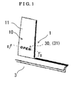
- Fig. 1 is a perspective view illustrating an appearance of a pillar garnish (exterior component) for a vehicle according to a first embodiment of the present invention
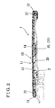
- Fig. 2 is a cross-sectional view taken on line II-II of Fig. 1 illustrating the pillar garnish according to the first embodiment of the present invention
- Fig. 3 is a cross-sectional view illustrating a pillar garnish for a vehicle according to a second embodiment of the present invention, the pillar garnish being modified from the pillar garnish for the vehicle according to the first embodiment;
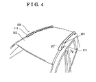
- Fig. 4 is a perspective view illustrating an appearance of a roof rail attached to a vehicle according to a third embodiment of the present invention.
- Fig. 5 is a cross-sectional view taken on line V-V of Fig. 4 illustrating the roof rail according to the third embodiment of the present invention
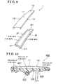
- Fig. 6 is a perspective view illustrating an appearance of the side protection molding attached to a vehicle according to a fourth embodiment of the present invention.
- Fig. 7 is a cross-sectional view taken on line VII-VII of Fig. 6 illustrating the side protection molding according to the fourth embodiment of the present invention
- Fig. 8 is a cross-sectional view illustrating a pillar garnish for a vehicle according to a fifth embodiment of the present invention.
- Fig. 9 is an exploded perspective view illustrating the pillar garnish according to the fifth embodiment of the present invention.
- Fig. 10 is a cross-sectional view illustrating a pillar garnish for a vehicle according to a sixth embodiment of the present invention.
- a garnish body of the pillar garnish includes a hard resin portion and a soft resin portion.
- Fig. 1 is a perspective view illustrating an appearance of a pillar garnish 1 (exterior component) for a vehicle according to the first embodiment of the present invention.
- the pillar garnish 1 includes a decorative surface 11 at an external portion of the pillar garnish 1.
- a light-emitting body 30 (light-emitting member) ( Fig. 2 ) provided in the pillar garnish 1 lights up and shuts off the light to display information (message) on the decorative surface 11 in cooperation with a function of a door 3.
- Fig. 2 is a cross-sectional view taken on line II-II of Fig. 1 illustrating the pillar garnish 1 according to the first embodiment of the present invention.
- the pillar garnish 1 includes a garnish cover 10 (first member), a garnish body 20 (second member) attached to a door sash 2 (vehicle) and the light-emitting body 30 provided between the garnish cover 10 and the garnish body 20.
- the garnish cover 10 and the garnish body 20 form a double layered structure of the pillar garnish 1.
- the light-emitting body 30 lights up and shuts off the light in response to a supply of electricity supplied by a wire harness (not illustrated) from the door sash 2 (vehicle).
- the garnish cover 10 is made with a plate of a uniform thickness of a material for transmitting light, such as acrylic, polyethylene terephthalate (PET), or the like.
- a translucent film 13 of metallic appearance is attached on a front surface of the garnish cover 10.
- a transmittance of the translucent film 13 is approximately 20%.
- a letters "OPEN”, which is information (message) display letters 14 (information display letter), is printed on a rear surface of the garnish cover 10.
- flange portions 12 (first engaging portion) are provided at both ends of the garnish cover 10.
- the garnish body 20 forms a structural portion of the pillar garnish 1.
- the garnish body 20 includes fitting portions 21 (second engaging portion), which engage with the flange portions 12.
- the garnish body 20 is made by a resin forming method.
- a resin material for forming the garnish body 20 can be selected from a resin containing glass fiber and a high-strength resin containing carbon fiber.
- the resin material for forming the garnish body 20 can also be selected from an inexpensive resin, for example, a recycled material, of which a surface quality is inferior, or the like.
- the light-emitting body 30 includes a light source such as a light-emitting diode (LED), a lamp, or the like.
- the light-emitting body 30 is provided at the garnish body 20.
- the wire harness (not illustrated) from the vehicle is connected to the light-emitting body 30.
- An organic electroluminecence 31 (organic EL) can be utilized as the light-emitting body 30 other than the LED, or the like.
- the pillar garnish 1 having the double layered structure of the garnish cover 10 and the garnish body 20 and the light-emitting body 30 provided between the garnish cover 10 and the garnish body 20 can replace an existing pillar garnish. Accordingly, because it is not necessary that the light-emitting body 30 is newly (separately) provided at a position which can be easily seen by a person around the vehicle, review of the structure of the door sash 2 and large shape change of the pillar garnish 1 are not required. Therefore, increase of cost can be restrained and a design of an appearance of the vehicle can be retained. Further, there are no adverse effects that the light-emitting body 30 makes contact with persons and that a protecting member is required for inhibiting degradation of the light-emitting body 30 caused by wind and rain, which increases the pillar garnish 1 in size.
- the garnish cover 10 includes the translucent film 13 of metallic appearance provided on the front surface of the garnish cover 10.
- the transmittance of the translucent film 13 is approximately 20%. Accordingly, the light-emitting body 30 is not visible in the appearance of the door sash 2 when the light-emitting body 30 is not emitting light. The light-emitting body 30 is visible as a display portion when the light-emitting body 30 is emitting light. Therefore, a design of an appearance of the door sash 2 can be retained.
- the organic EL 31 when utilized as the light-emitting body, an image, information (message) according to functions, and a color image can be displayed. Therefore, visual effect to an occupant, or the like, can be enhanced.
- FIG. 3 is a cross-sectional view illustrating a pillar garnish 1 for a vehicle according to the second embodiment of the present invention.
- a pillar garnish 1 for a vehicle according to the second embodiment some parts of the pillar garnish 1 for the vehicle according to the first embodiment are changed. Parts and shapes, which are common with those of the first embodiment, will be explained with use of common reference numerals. Difference of the second embodiment with the first embodiment will be mainly explained.
- a resin plate 40 for transmitting light is provided at a position between the garnish cover 10 and the light-emitting body 30.
- the resin plate 40 makes contact with the light-emitting body 30.
- the information (message) display letter 14 is provided on the resin plate 40.
- the resin plate 40 on which the information (message) display letter 14 is provided, is provided at the position between the garnish cover 10 and the light-emitting body 30, and the resin plate 40 makes contact with the light-emitting body 30, light emitted from the light-emitting body 30 transmits through the printed information (message) display letter 14 and the information (message) display letter 14 is projected on the rear surface of the garnish cover 10.
- both of the resin plate 40, on which the information (message) display letter 14 is provided, and the garnish cover 10 are lit.
- the garnish cover 10 on which the translucent film 13 of metallic appearance is attached, is seen from an angled direction, the information (message) display letter 14 on the resin plate 40 can be seen through the garnish cover 10.
- the information (message) display letter 14 is seen as a letter with a shadow. Therefore, a stereoscopic display effects, in which the information (message) display letter 14 is seen as the information (message) display letter 14 is raised from an outside of the vehicle (door sash 2), can be obtained.
- Figs. 4 and 5 are figures illustrating a roof rail 101 (exterior component) for a vehicle according to the third embodiment of the present invention.
- Fig. 4 is a perspective view illustrating an appearance of the roof rail 101 attached to the vehicle 102.
- the roof rail 101 includes a decorative surface 111 formed at an external portion of the roof rail 101.
- a light-emitting body 130 (light-emitting member) ( Fig. 5 ) is provided in the roof rail 101. The light-emitting body 130 lights up and shuts off the light to display information (message) on the decorative surface 111.
- Fig. 5 is a cross-sectional view taken from V-V of Fig. 4 illustrating the roof rail 101 according to the third embodiment of the present invention.
- the roof rail 101 includes a roof rail cover 110 (first member), a roof rail body 120 (second member) attached to the vehicle 102 and the light-emitting body 130 provided between the roof rail cover 110 and the roof rail body 120.
- the roof rail cover 110 and the roof rail body 120 form a double layered structure of the roof rail 101.
- the light-emitting body 130 lights up and shuts off the light according to a supply of electricity supplied by a wire harness (not illustrated) from the vehicle 102.
- the roof rail cover 110 is made with a material for transmitting light, such as acrylic, PET, or the like.
- a translucent film 113 of metallic appearance is attached on a front surface of the roof rail cover 110.
- a transmittance of the translucent film 113 is approximately 20%.
- First engaging portions 112 are provided at both ends of the roof rail cover 110.
- the roof rail body 120 forms a structural portion of the roof rail 101.
- the roof rail body 120 includes second engaging portions 121, which engage with the first engaging portions 112 of the roof rail cover 110.
- the roof rail cover 110 and the roof rail body 120 form the double layered structure of the roof rail 101 when the first engaging portions 112 of the roof rail cover 110 engage with the second engaging portions 121 of the roof rail body 120.
- the roof rail body 120 is made by resin forming method.
- the resin material for forming the roof rail body 120 can be selected from a resin containing glass fiber and a high-strength resin containing carbon fiber.
- the resin material for forming the roof rail body 120 can also be selected from an inexpensive resin, for example, a recycled material, of which a surface quality is inferior, or the like.
- the light-emitting body 130 includes a light source such as an LED, a lamp, or the like.
- the light-emitting body 130 is provided at the roof rail body 120.
- the wire harness (not illustrated) from the vehicle 102 is connected to the light-emitting body 130.
- An organic EL 131 can be utilized as the light-emitting body 130 other than the LED, or the like.
- the roof rail 101 according to the third embodiment has effects similar to the first embodiment and the second embodiment.
- FIGs. 6 and 7 are figures illustrating a side protection molding 201 (exterior component) for a vehicle according to the fourth embodiment of the present invention.
- Fig. 6 is a perspective view illustrating an appearance of the side protection molding 201 attached to the vehicle 202.
- the side protection molding 201 includes a decorative surface 211 formed at an external portion of the side protection molding 201.
- a light-emitting body 230 (light-emitting member) ( Fig. 7 ) is provided in the side protection molding 201. The light-emitting body 230 lights up and shuts off the light to display information (message) on the decorative surface 211.
- Fig. 7 is a cross-sectional view taken on line VII-VII of Fig. 6 illustrating the side protection molding 201 according to the fourth embodiment of the present invention.
- the side protection molding 201 includes a side protection molding cover 210 (first member), a side protection molding body 220 (second member) attached to the vehicle 202 and the light-emitting body 230 provided between the side protection molding cover 210 and the side protection molding body 220.
- the side protection molding cover 210 and the side protection molding body 220 form a double layered structure of the side protection molding 201.
- the light-emitting body 230 lights up and shuts off the light according to a supply of electricity supplied by a wire harness (not illustrated) from the vehicle 202.
- the side protection molding cover 210 is made with a material for transmitting light, such as acrylic, PET, or the like.
- a translucent film 213 of metallic appearance is attached on a front surface of the side protection molding cover 210.
- a transmittance of the translucent film 213 is approximately 20%.
- First engaging portions 212 are provided at both ends of the side protection molding cover 210.
- the side protection molding body 220 forms a structural portion of the side protection molding 201.
- the side protection molding body 220 includes second engaging portions 221, which engage with the first engaging portions 212 of the side protection molding cover 210.
- the side protection molding cover 210 and the side protection molding body 220 form the double layered structure of the side protection molding 201 when the first engaging portions 212 of the side protection molding cover 210 engage with the second engaging portions 221 of the side protection molding cover 220.
- the side protection molding body 220 is made by resin forming method.
- the resin material for forming the side protection molding body 220 can be selected from a resin containing glass fiber and a high-strength resin containing carbon fiber.
- the resin material for forming the side protection molding body 220 can also be selected from an inexpensive resin, for example, a recycled material, of which a surface quality is inferior, or the like.
- the light-emitting body 230 includes a light source such as an LED, a lamp, or the like.
- the light-emitting body 230 is provided at the side protection molding body 220.
- the wire harness (not illustrated) from the vehicle 202 is connected to the light-emitting body 230.
- An organic EL 231 can be utilized as the light-emitting body 230 other than the LED, or the like.
- the side protection molding 201 according to the fourth embodiment has effects similar to the first embodiment and the second embodiment.
- Fig. 8 is a cross-sectional view illustrating a pillar garnish 1 (exterior component) for a vehicle according to the fifth embodiment of the present invention.
- the pillar garnish 1 includes a garnish cover 10 (first member) and a garnish body 20 (second member).
- the garnish cover 10 includes a decorative surface 11 formed at an external portion of the garnish cover 10 and flange portions 12 (first engaging portion) formed at both of end portions of the garnish cover 10.
- the garnish body 20 includes a rib 321 and fitting portions 21 (second engaging portion).
- the garnish body 20 is attached to a door sash 330 (vehicle) by a clip portion 342 (attaching portion) ( Fig. 10 ).
- the flange portions 12 of the garnish cover 10 fit (engage) with the fitting portions 21 of the garnish body 20.
- the garnish cover 10 is made with a plate of aluminum material, which has a uniform thickness. Both end portions of the plate are bent to form the flange portions 12. Further, the plate is processed by almite after the flange portions 12 are formed. Other than the almite processing, attaching of an exterior film, painting, printing, or the like, can be applied to the plate. Accordingly, various designs of the garnish cover 10 are available.
- the garnish body 20 forms a structural portion of the pillar garnish 1.
- the garnish body 20 includes the rib 321, the fitting portions 21 and the clip portion 342 ( Fig. 10 ), which are extending in a lengthwise direction of the garnish body 20.
- the garnish body 20 is made by resin forming method as a unit with the rib 321, the fitting portions 21, and the clip portion 342.
- the resin material for forming the garnish body 20 can be selected from a resin containing glass fiber and a high-strength resin containing carbon fiber.
- the resin material for forming the garnish body 20 can also be selected from a resin, which is easily degraded by ultraviolet ray, and an inexpensive resin, for example, a recycled material, of which a surface quality is inferior, or the like.
- Fig. 9 is an exploded perspective view of the pillar garnish 1.
- the decorative surface 11 of the garnish cover 10 is structured so that the decorative surface 11 covers an entire part of the garnish body 20. Accordingly, a sink mark, which is made when the garnish body 20 is made by resin forming method, and the fitting portions 21 are not seen from an external side of the pillar garnish 1.
- the pillar garnish 1 includes the garnish cover 10, which includes the decorative surface 11 formed at the external portion of the garnish cover 10, and the garnish body 20, which forms the structural portion attached to the door sash 330. Accordingly, even when the rib 321 and the clip portion 342 ( Fig. 10 ) are provided at the garnish body 20 and the sink mark is made at the garnish body 20, the sink mark is covered by the garnish cover 10. Therefore, an appearance of the pillar garnish 1 is not degraded. Further, because the garnish cover 10 is formed as a unit, the pillar garnish 1 can have a solid appearance. Accordingly, dimensional precision controls and adjustments between components for each product, which are required for the known door sash, are not required.
- the garnish cover 10 which includes the flange portions 12, has a simple shape, attaching of an exterior film, painting, printing, or the like, can be applied to the garnish cover 10. Accordingly, various designs of the garnish cover 10 are available. Further, because appearance quality of the garnish body 20 is not required, an optimum shape and a material (a resin containing glass fiber, a high-strength resin containing carbon fiber, a resin, which is easily degraded by ultraviolet ray, an inexpensive resin, for example, a recycled material, of which a surface quality is inferior, or the like) can be selected for retaining rigidity of the garnish body 20 to be attached to the garnish cover 10 and to the door sash 330. Further, because a position of the rib 321 at the garnish body 20 is not restrained by the design and the structure of the garnish body 20, degree of freedom of design of the garnish body 20 can be enhanced.
- the garnish cover 10 can be made with a plate, which has a uniform thickness.
- the material of the plate can be selected from various materials, for example, a metal (aluminum, stainless used steel (SUS), iron, titanium, or the like) and a resin (polypropylene (PP), polyethylene (PE), acrylic resin (AC), acrylonitrile-butadiene-styrene (ABS), polycarbonate (PC), or the like).
- FIG. 10 is a cross-sectional view illustrating a pillar garnish 402 (exterior component) for a vehicle according to the sixth embodiment of the present invention. Parts and shapes of the sixth embodiment, which are common with those of the fifth embodiment, will be explained with use of common reference numerals. Differences of the sixth embodiment with the fifth embodiment will be mainly explained.
- the pillar garnish 402 includes the garnish cover 10, which forms the decorative surface 11 of the external portion of the garnish cover 10, and a garnish body 440 (second member).
- a structural portion 441 of the garnish body 440 is made with a hard resin.
- the clip portion 342 (attaching portion) of the garnish body 440 is made with a soft resin.
- the clip portion 342 is attached to the door sash 330.
- the structural portion 441 and the clip portion 342 of the garnish body 440 are made by a double molding as a unit.
Applications Claiming Priority (3)
| Application Number | Priority Date | Filing Date | Title |
|---|---|---|---|
| JP2007301730 | 2007-11-21 | ||
| JP2008073919A JP2009143520A (ja) | 2007-11-21 | 2008-03-21 | 車両用外装部品 |
| JP2008073921A JP5338098B2 (ja) | 2007-11-21 | 2008-03-21 | 車両用外装部品 |
Publications (2)
| Publication Number | Publication Date |
|---|---|
| EP2062784A2 true EP2062784A2 (de) | 2009-05-27 |
| EP2062784A3 EP2062784A3 (de) | 2013-01-02 |
Family
ID=40414090
Family Applications (1)
| Application Number | Title | Priority Date | Filing Date |
|---|---|---|---|
| EP08253778A Withdrawn EP2062784A3 (de) | 2007-11-21 | 2008-11-20 | Außenbauteil für Fahrzeug |
Country Status (2)
| Country | Link |
|---|---|
| US (1) | US7914189B2 (de) |
| EP (1) | EP2062784A3 (de) |
Cited By (9)
| Publication number | Priority date | Publication date | Assignee | Title |
|---|---|---|---|---|
| WO2011154667A1 (fr) * | 2010-06-11 | 2011-12-15 | Peugeot Citroën Automobiles SA | Garniture de longeron d'un vehicule automobile |
| WO2014186659A1 (en) * | 2013-05-16 | 2014-11-20 | Magna International Inc. | Accent lighting of automotive roof rails |
| WO2015058908A1 (de) * | 2013-09-19 | 2015-04-30 | Kunststoff-Technik Scherer & Trier Gmbh & Co Kg | Abdeckungseinrichtung, system, karosseriebauteil, karosseriebauteilsystem und fahrzeug |
| US9421922B2 (en) | 2011-09-23 | 2016-08-23 | Saint-Gobain Glass France | Pillar covering for motor vehicles |
| EP3299217A1 (de) * | 2013-09-19 | 2018-03-28 | Samvardhana Motherson Innovative Autosystems B.V. & Co. KG | Abdeckungseinrichtung, system, karosseriebauteil, karosseriebauteilsystem und fahrzeug |
| EP3421278A1 (de) * | 2017-06-29 | 2019-01-02 | DURA Operating, LLC | Beleuchtete zierleiste |
| WO2020144140A1 (en) * | 2019-01-10 | 2020-07-16 | Motherson Innovations Company Ltd. | Covering device, body part and motor vehicle |
| EP3228501B1 (de) * | 2016-03-17 | 2022-05-04 | Seat, S.A. | Beleuchtungsvorrichtung für eine äussere abdeckung auf einer seite eines fahrzeugs |
| US11519585B2 (en) | 2012-01-24 | 2022-12-06 | SMR Patent S.à.r.l. | Covering devices for use with vehicle parts |
Families Citing this family (5)
| Publication number | Priority date | Publication date | Assignee | Title |
|---|---|---|---|---|
| US8698610B2 (en) | 2010-07-14 | 2014-04-15 | John Adam Krugh, IV | Elevated stop indicator lights for passenger bus |
| US8414168B2 (en) * | 2010-08-09 | 2013-04-09 | Gm Global Technology Operations, Llc | Roof rack assembly with integrated lighting |
| DE102010034927A1 (de) | 2010-08-20 | 2012-02-23 | Gm Global Technology Operations Llc (N.D.Ges.D. Staates Delaware) | Vorrichtung zur Außenbeleuchtung eines Fahrzeugs und Verfahren zum Betreiben der Vorrichtung |
| JP6131675B2 (ja) * | 2013-03-28 | 2017-05-24 | アイシン精機株式会社 | ルーフレール |
| JP6612302B2 (ja) | 2017-11-10 | 2019-11-27 | シロキ工業株式会社 | ドアサッシュ |
Citations (2)
| Publication number | Priority date | Publication date | Assignee | Title |
|---|---|---|---|---|
| JP2004338522A (ja) | 2003-05-15 | 2004-12-02 | Katayama Kogyo Co Ltd | 車両用ドアサッシュ |
| JP2005247182A (ja) | 2004-03-05 | 2005-09-15 | Honda Motor Co Ltd | 自動車のピラーガーニッシュ構造 |
Family Cites Families (7)
| Publication number | Priority date | Publication date | Assignee | Title |
|---|---|---|---|---|
| JPS5856942A (ja) * | 1981-09-29 | 1983-04-04 | Nissan Motor Co Ltd | 車両用ウインドガラスにおけるマ−ク表示構造 |
| JPS60166500A (ja) * | 1984-02-10 | 1985-08-29 | 豊田合成株式会社 | 装飾部材 |
| JP2004247182A (ja) | 2003-02-14 | 2004-09-02 | Ube Ind Ltd | 燃料電池用電解質膜、電解質膜−電極接合体、燃料電池および燃料電池用電解質膜の製造方法 |
| US20060114685A1 (en) * | 2004-11-30 | 2006-06-01 | Patrick Seeber | Vehicle-mounted illuminated display |
| EP1924985A2 (de) * | 2005-08-22 | 2008-05-28 | Stephen P. Rosa | Verbessertes echtfarben-tag-nacht-graphiksystem und zusammenbauverfahren |
| US7387397B2 (en) * | 2005-08-25 | 2008-06-17 | Nissan Technical Center North America, Inc. | Vehicle backlit panel |
| JP4905105B2 (ja) * | 2006-04-28 | 2012-03-28 | 株式会社豊田自動織機 | 表示装置 |
-
2008
- 2008-11-20 EP EP08253778A patent/EP2062784A3/de not_active Withdrawn
- 2008-11-20 US US12/292,517 patent/US7914189B2/en not_active Expired - Fee Related
Patent Citations (2)
| Publication number | Priority date | Publication date | Assignee | Title |
|---|---|---|---|---|
| JP2004338522A (ja) | 2003-05-15 | 2004-12-02 | Katayama Kogyo Co Ltd | 車両用ドアサッシュ |
| JP2005247182A (ja) | 2004-03-05 | 2005-09-15 | Honda Motor Co Ltd | 自動車のピラーガーニッシュ構造 |
Cited By (14)
| Publication number | Priority date | Publication date | Assignee | Title |
|---|---|---|---|---|
| FR2961147A1 (fr) * | 2010-06-11 | 2011-12-16 | Peugeot Citroen Automobiles Sa | Garniture de longeron d'un vehicule automobile |
| WO2011154667A1 (fr) * | 2010-06-11 | 2011-12-15 | Peugeot Citroën Automobiles SA | Garniture de longeron d'un vehicule automobile |
| US9421922B2 (en) | 2011-09-23 | 2016-08-23 | Saint-Gobain Glass France | Pillar covering for motor vehicles |
| US11519585B2 (en) | 2012-01-24 | 2022-12-06 | SMR Patent S.à.r.l. | Covering devices for use with vehicle parts |
| US9937868B2 (en) | 2013-05-16 | 2018-04-10 | Magna International Inc. | Accent lighting of automotive roof rails |
| WO2014186659A1 (en) * | 2013-05-16 | 2014-11-20 | Magna International Inc. | Accent lighting of automotive roof rails |
| CN105228858A (zh) * | 2013-05-16 | 2016-01-06 | 麦格纳国际公司 | 汽车车顶纵梁的重点照明 |
| CN105228858B (zh) * | 2013-05-16 | 2019-03-15 | 麦格纳国际公司 | 汽车车顶纵梁的重点照明 |
| WO2015058908A1 (de) * | 2013-09-19 | 2015-04-30 | Kunststoff-Technik Scherer & Trier Gmbh & Co Kg | Abdeckungseinrichtung, system, karosseriebauteil, karosseriebauteilsystem und fahrzeug |
| EP3299217A1 (de) * | 2013-09-19 | 2018-03-28 | Samvardhana Motherson Innovative Autosystems B.V. & Co. KG | Abdeckungseinrichtung, system, karosseriebauteil, karosseriebauteilsystem und fahrzeug |
| CN105764751A (zh) * | 2013-09-19 | 2016-07-13 | 舍雷尔&特里尔塑料技术两合股份有限公司 | 覆盖装置、系统、车身部件、车身部件系统和车辆 |
| EP3228501B1 (de) * | 2016-03-17 | 2022-05-04 | Seat, S.A. | Beleuchtungsvorrichtung für eine äussere abdeckung auf einer seite eines fahrzeugs |
| EP3421278A1 (de) * | 2017-06-29 | 2019-01-02 | DURA Operating, LLC | Beleuchtete zierleiste |
| WO2020144140A1 (en) * | 2019-01-10 | 2020-07-16 | Motherson Innovations Company Ltd. | Covering device, body part and motor vehicle |
Also Published As
| Publication number | Publication date |
|---|---|
| US7914189B2 (en) | 2011-03-29 |
| US20090129106A1 (en) | 2009-05-21 |
| EP2062784A3 (de) | 2013-01-02 |
Similar Documents
| Publication | Publication Date | Title |
|---|---|---|
| US7914189B2 (en) | Exterior component for vehicle | |
| US10940810B2 (en) | Trim element on a vehicle and method of manufacturing same | |
| US9616807B2 (en) | Vehicle functional component | |
| US20120280528A1 (en) | Vehicle accent molding with puddle light | |
| JP2009143520A (ja) | 車両用外装部品 | |
| US6735893B2 (en) | Sign for a vehicle and process of using sign | |
| US11312292B2 (en) | Luminous motor-vehicle glazing unit | |
| KR100921306B1 (ko) | 자동차 도어스커프용 장식장치 | |
| CN201626355U (zh) | 具有发光条灯的车门内饰板 | |
| US10571690B2 (en) | Automotive window with transparent light guide display | |
| JP2014094656A (ja) | 加飾照明装置 | |
| JP2006205750A (ja) | 車両用照明装置 | |
| WO2010080945A1 (en) | Interior trim panel, method for illuminating an interior trim panel and method for producing an interior trim panel | |
| KR100701995B1 (ko) | 차량용 도어 스커프 | |
| RU2639931C1 (ru) | Световое информационное табло с заменяемой лицевой панелью, встроенное в противосолнечный козырек автомобиля | |
| US9744918B2 (en) | Vehicle decoration structure | |
| US11420746B2 (en) | Interior panel for an interior of an aircraft and a method for making the same | |
| WO2017123747A1 (en) | Vehicle trim component with concealable indicia defined by micro-holes | |
| JP2017095045A (ja) | 車両用照明構造 | |
| JP3130297U (ja) | カードアのサイドプロテクションモール | |
| CN212556090U (zh) | 一种汽车内饰发光面板 | |
| JP2006193096A (ja) | 発光式オーナメント | |
| KR200245916Y1 (ko) | 광고 기능을 겸비한 보조 정지등 | |
| CN102381224A (zh) | 一种带有灯光系统的汽车外车门拉手 | |
| JP2007314166A (ja) | 自動車用サイドバイザー |
Legal Events
| Date | Code | Title | Description |
|---|---|---|---|
| PUAI | Public reference made under article 153(3) epc to a published international application that has entered the european phase |
Free format text: ORIGINAL CODE: 0009012 |
|
| AK | Designated contracting states |
Kind code of ref document: A2 Designated state(s): AT BE BG CH CY CZ DE DK EE ES FI FR GB GR HR HU IE IS IT LI LT LU LV MC MT NL NO PL PT RO SE SI SK TR |
|
| AX | Request for extension of the european patent |
Extension state: AL BA MK RS |
|
| PUAL | Search report despatched |
Free format text: ORIGINAL CODE: 0009013 |
|
| AK | Designated contracting states |
Kind code of ref document: A3 Designated state(s): AT BE BG CH CY CZ DE DK EE ES FI FR GB GR HR HU IE IS IT LI LT LU LV MC MT NL NO PL PT RO SE SI SK TR |
|
| AX | Request for extension of the european patent |
Extension state: AL BA MK RS |
|
| RIC1 | Information provided on ipc code assigned before grant |
Ipc: B60Q 1/32 20060101ALI20121126BHEP Ipc: G09F 21/04 20060101ALI20121126BHEP Ipc: B60R 13/00 20060101ALI20121126BHEP Ipc: B60R 9/04 20060101AFI20121126BHEP Ipc: B60R 13/04 20060101ALI20121126BHEP Ipc: B60Q 1/26 20060101ALI20121126BHEP |
|
| 17P | Request for examination filed |
Effective date: 20130628 |
|
| RBV | Designated contracting states (corrected) |
Designated state(s): AT BE BG CH CY CZ DE DK EE ES FI FR GB GR HR HU IE IS IT LI LT LU LV MC MT NL NO PL PT RO SE SI SK TR |
|
| RBV | Designated contracting states (corrected) |
Designated state(s): AT BE BG CH CY CZ DE DK EE ES FI FR GB GR HR HU IE IS IT LI LT LU LV MC MT NL NO PL PT RO SE SI SK TR |
|
| AKX | Designation fees paid |
Designated state(s): DE FR |
|
| 17Q | First examination report despatched |
Effective date: 20130923 |
|
| STAA | Information on the status of an ep patent application or granted ep patent |
Free format text: STATUS: THE APPLICATION IS DEEMED TO BE WITHDRAWN |
|
| 18D | Application deemed to be withdrawn |
Effective date: 20140204 |