EP2062716A1 - Injection molding machine - Google Patents
Injection molding machine Download PDFInfo
- Publication number
- EP2062716A1 EP2062716A1 EP07805952A EP07805952A EP2062716A1 EP 2062716 A1 EP2062716 A1 EP 2062716A1 EP 07805952 A EP07805952 A EP 07805952A EP 07805952 A EP07805952 A EP 07805952A EP 2062716 A1 EP2062716 A1 EP 2062716A1
- Authority
- EP
- European Patent Office
- Prior art keywords
- nozzle
- mold
- resin
- receiving section
- molding
- Prior art date
- Legal status (The legal status is an assumption and is not a legal conclusion. Google has not performed a legal analysis and makes no representation as to the accuracy of the status listed.)
- Withdrawn
Links
Images


Classifications
-
- B—PERFORMING OPERATIONS; TRANSPORTING
- B29—WORKING OF PLASTICS; WORKING OF SUBSTANCES IN A PLASTIC STATE IN GENERAL
- B29C—SHAPING OR JOINING OF PLASTICS; SHAPING OF MATERIAL IN A PLASTIC STATE, NOT OTHERWISE PROVIDED FOR; AFTER-TREATMENT OF THE SHAPED PRODUCTS, e.g. REPAIRING
- B29C45/00—Injection moulding, i.e. forcing the required volume of moulding material through a nozzle into a closed mould; Apparatus therefor
- B29C45/17—Component parts, details or accessories; Auxiliary operations
- B29C45/38—Cutting-off equipment for sprues or ingates
-
- B—PERFORMING OPERATIONS; TRANSPORTING
- B29—WORKING OF PLASTICS; WORKING OF SUBSTANCES IN A PLASTIC STATE IN GENERAL
- B29C—SHAPING OR JOINING OF PLASTICS; SHAPING OF MATERIAL IN A PLASTIC STATE, NOT OTHERWISE PROVIDED FOR; AFTER-TREATMENT OF THE SHAPED PRODUCTS, e.g. REPAIRING
- B29C45/00—Injection moulding, i.e. forcing the required volume of moulding material through a nozzle into a closed mould; Apparatus therefor
- B29C45/17—Component parts, details or accessories; Auxiliary operations
- B29C45/20—Injection nozzles
-
- B—PERFORMING OPERATIONS; TRANSPORTING
- B29—WORKING OF PLASTICS; WORKING OF SUBSTANCES IN A PLASTIC STATE IN GENERAL
- B29C—SHAPING OR JOINING OF PLASTICS; SHAPING OF MATERIAL IN A PLASTIC STATE, NOT OTHERWISE PROVIDED FOR; AFTER-TREATMENT OF THE SHAPED PRODUCTS, e.g. REPAIRING
- B29C45/00—Injection moulding, i.e. forcing the required volume of moulding material through a nozzle into a closed mould; Apparatus therefor
- B29C45/17—Component parts, details or accessories; Auxiliary operations
- B29C45/26—Moulds
-
- B—PERFORMING OPERATIONS; TRANSPORTING
- B29—WORKING OF PLASTICS; WORKING OF SUBSTANCES IN A PLASTIC STATE IN GENERAL
- B29C—SHAPING OR JOINING OF PLASTICS; SHAPING OF MATERIAL IN A PLASTIC STATE, NOT OTHERWISE PROVIDED FOR; AFTER-TREATMENT OF THE SHAPED PRODUCTS, e.g. REPAIRING
- B29C45/00—Injection moulding, i.e. forcing the required volume of moulding material through a nozzle into a closed mould; Apparatus therefor
- B29C45/17—Component parts, details or accessories; Auxiliary operations
- B29C45/46—Means for plasticising or homogenising the moulding material or forcing it into the mould
- B29C45/56—Means for plasticising or homogenising the moulding material or forcing it into the mould using mould parts movable during or after injection, e.g. injection-compression moulding
- B29C45/561—Injection-compression moulding
-
- B—PERFORMING OPERATIONS; TRANSPORTING
- B29—WORKING OF PLASTICS; WORKING OF SUBSTANCES IN A PLASTIC STATE IN GENERAL
- B29C—SHAPING OR JOINING OF PLASTICS; SHAPING OF MATERIAL IN A PLASTIC STATE, NOT OTHERWISE PROVIDED FOR; AFTER-TREATMENT OF THE SHAPED PRODUCTS, e.g. REPAIRING
- B29C45/00—Injection moulding, i.e. forcing the required volume of moulding material through a nozzle into a closed mould; Apparatus therefor
- B29C45/17—Component parts, details or accessories; Auxiliary operations
- B29C45/72—Heating or cooling
-
- B—PERFORMING OPERATIONS; TRANSPORTING
- B29—WORKING OF PLASTICS; WORKING OF SUBSTANCES IN A PLASTIC STATE IN GENERAL
- B29C—SHAPING OR JOINING OF PLASTICS; SHAPING OF MATERIAL IN A PLASTIC STATE, NOT OTHERWISE PROVIDED FOR; AFTER-TREATMENT OF THE SHAPED PRODUCTS, e.g. REPAIRING
- B29C45/00—Injection moulding, i.e. forcing the required volume of moulding material through a nozzle into a closed mould; Apparatus therefor
- B29C45/17—Component parts, details or accessories; Auxiliary operations
- B29C45/26—Moulds
- B29C45/263—Moulds with mould wall parts provided with fine grooves or impressions, e.g. for record discs
-
- Y—GENERAL TAGGING OF NEW TECHNOLOGICAL DEVELOPMENTS; GENERAL TAGGING OF CROSS-SECTIONAL TECHNOLOGIES SPANNING OVER SEVERAL SECTIONS OF THE IPC; TECHNICAL SUBJECTS COVERED BY FORMER USPC CROSS-REFERENCE ART COLLECTIONS [XRACs] AND DIGESTS
- Y10—TECHNICAL SUBJECTS COVERED BY FORMER USPC
- Y10S—TECHNICAL SUBJECTS COVERED BY FORMER USPC CROSS-REFERENCE ART COLLECTIONS [XRACs] AND DIGESTS
- Y10S425/00—Plastic article or earthenware shaping or treating: apparatus
- Y10S425/81—Sound record
Definitions
- the present invention relates to an injection molding machine that molds a molding product using a mold, and more particularly, to an injection molding machine intended to improve molding efficiency when a molding product is molded without forming any sprue together with the molding to be a product.
- a conventional common injection molding machine molds a molding product by sending granular thermoplastic resin, which is a raw material, into a heating cylinder, sending out resin using a screw provided inside the heating cylinder and movable forward/backward, to a nozzle at an end of the screw while melting the resin, causing the melted resin to be injected from the nozzle provided at the end of the screw into a cavity of a mold, causing the melted resin to cool and solidify in the cavity, then opening the mold and removing a molded product stuck to the mold from the mold using a protruding pin or the like.
- Such an injection molding machine for molding a molding product such as plastics is generally constructed of a mold clamping unit and an injection unit, and the mold clamping unit is generally provided with a mold including a fixed mold and a movable mold, the movable mold is made to move forward/backward to/from the fixed mold through movable means capable of mold clamping such as a toggle mechanism or straight hydraulic scheme and the mold is thereby closed or opened during mold clamping.
- An injection unit is used when pellet, which is granular resin is supplied as melted resin into the cavity formed during mold clamping of the mold of the aforementioned mold, and this injection unit is provided with drive means such as a motor as the drive source, the torque of the motor is sequentially transmitted via a pulley, belt or the like, the screw in the heating cylinder is rotated by a ball screw mechanism that converts rotary motion to linear motion, the melted resin is thereby transferred, and the melted resin is then injected from the nozzle into the cavity between the molds provided in the mold clamping unit.
- drive means such as a motor as the drive source
- Patent Document 1 discloses a runnerless mold that provides a recessed part in the center of a fixed mold, which is one of the fixed mold and a movable mold that make up a cavity, provides a compression core that engages with this recessed part in the center of the movable mold in a manner movable forward/backward, causes an end of a hot nozzle inserted in the fixed mold to protrude in the center of the recessed part, forms a runner section that is opened/closed by the compression core between the recessed part and compression core and leaves a resin layer in the recessed part when the compression core moves forward.
- Patent Document 1 Japanese Patent Laid-Open No. 8-281714
- Patent Document 1 when the compression core moves forward in molding after the resin layer is left in the recessed part, since resin remaining in the recessed part is concave shaped in the recessed part and the thickness of the resin layer is approximately 1/2 of the thickness of the molded product (see Figure 4 in Patent Document 1), relatively thick resin layers are inevitably left in the recessed part and the remaining resin layers are stacked every time molding is performed and the thickness of the resin layer changes. That the thickness of the resin layer changes means that the size of the gate also changes, which may adversely influence molding quality.
- a sprue is molded linked with the molding product to be a product.
- This sprue is separated from the molding product to be a product in the mold during injection molding, the molding product and sprue are ejected from the mold using an ejection apparatus after mold opening, and therefore the work of removing the sprue from the molding product to be a product requires time and the removed sprue is not used as a product, and this results in useless production leading to an increase of production cost.
- the present invention is intended to solve the above described problems and it is an object of the present invention to provide an injection molding machine designed to improve quality of a molded molding product, prevent molded parts which are not used as a product to be molded from being uselessly produced together with the molding product to be a product and thereby improve production efficiency.
- the injection molding machine is configured to provide a nozzle receiving section configured on a fixed mold side of a cavity formed of the fixed mold and a movable mold so as to slightly protrude toward the movable mold, a core section facing the nozzle receiving section in the movable mold in a manner movable forward/backward, an end of the nozzle being placed on substantially the same plane as that of an end of the nozzle receiving section, and a protruding part at a position of the core section facing the end of the nozzle that injects melted resin, wherein a gate of the resin injected into the cavity is cut by moving the core section forward and moving backward the nozzle receiving section and the nozzle pressed by the core section which has been moved forward so that the gate cutting causes a film of the resin to remain at the ends of the nozzle receiving section and the nozzle.
- the melted resin injected from the nozzle is filled from the gate into the cavity, and when the core section moves forward, the forward movement of the core section causes the nozzle receiving section and nozzle to be pressed and move backward, gate cutting is performed, and then the movable mold moves backward and mold opening is performed.
- resin existing between the core section, nozzle receiving section and nozzle is cooled and solidified, united with resin filling the interior of the nozzle, thereby remains in a film shape at the end of the nozzle receiving section and nozzle, and therefore by melting the remaining resin when filling resin into the cavity in the next cycle with heat from the melted resin supplied from the nozzle or the like and using the resin as resin to be filled into the cavity, it is possible to use the resin as part of a molding product molded in the next molding cycle.
- the protruding part is provided at the position of the core section facing the end of the nozzle which injects melted resin, the protruding part enters the nozzle at the end thereof and makes it possible to reduce cold slug that remains inside the nozzle at the end thereof which may cause molding defect (appearance defect).
- the injection molding machine according to claim 2 is the injection molding machine according to claim 1, wherein the nozzle is provided with a heater.
- the film-shaped resin when the solidified, remaining film-shaped melted resin is filled into the cavity, the film-shaped resin is heated and melted using the heater provided for the nozzle, and it is thereby possible to fill the film-shaped melted resin together with the melted resin supplied from the nozzle into the cavity.
- the injection molding machine is configured to provide a nozzle receiving section configured on a fixed mold side of a cavity formed of the fixed mold and a movable mold so as to slightly protrude toward the movable mold, a core section facing the nozzle receiving section in the movable mold in a manner movable forward/backward, an end of the nozzle being placed on substantially the same plane as that of an end of the nozzle receiving section, and a protruding part at a position of the core section facing the end of the nozzle that injects melted resin, wherein a gate of the resin injected into the cavity is cut by moving the core section forward and moving backward the nozzle receiving section and the nozzle pressed by the core section which has been moved forward so that the gate cutting causes a film of the resin to remain at the ends of the nozzle receiving section and the nozzle, and therefore the remaining resin can be used as part of the molding product to be molded in the next molding cycle. Therefore, when molding a molding product, it is possible to prevent the molded part not to
- the invention of the injection molding machine according to claim 2 is the injection molding machine according to claim 1, wherein the nozzle is provided with a heater. This allows the solidified, remaining film-shaped resin to be used as part of the molding product.
- Figure 1 is a partially cut out side view of a mold of an injection molding machine in a mold opening state showing an example of the present invention
- Figure 2 to Figure 6 are enlarged cross-sectional views of main parts of the mold configured on the injection molding machine.
- the injection molding machine 1 includes a machine base 2 and an injection unit 3, a mold clamping unit 4 and a mold 5 are arranged on this machine base 2.
- the injection unit 3 is designed to send out melted resin into a cavity C of a mold by rotating a screw 6 of this injection unit 3, there is a hopper 7 into which resin (pellet), which is a granular raw material, is deposited in the upper part of the injection unit 3 so that granular resin drops from the hopper 7 under its own weight into a cylindrical heating cylinder 8 provided below the hopper 7.
- resin pellet
- the injection unit 3 is intended to rotate the screw 6 and measure the amount of melted resin supplied into the heating cylinder 8 and heated, is provided with a screw rotation drive motor 9, which is a drive source, and when a pulley 11 fixed to a rotating shaft 10 of this screw rotation drive motor 9 rotates the rear part of the screw 6 via a measuring drive timing belt 12 and thereby causes the screw 6 to rotate in conjunction therewith.
- an injection drive motor is fixed to a back side support frame 13 placed on the machine base 2, intended to rotate a ball screw section 14 configured in a ball screw unit, which will be described later, via a drive transmission mechanism made up of a pulley of the injection drive motor and an injection drive timing belt or the like, and a front side support frame 15 and the back side support frame 13 fixed onto the machine base 2 are connected together by cylindrical tie bars 17.
- a nut section 16 configured in the ball screw unit holds the screw 6 in a rotatable manner and is attached to a screw holding plate 18 which is guided by the tie bars 17. Furthermore, the screw rotation drive motor 9 is fixed to the screw holding plate 18 and is designed to inject melted resin into the cavity C when the nut section 16 is moved forward by the injection drive motor and ball screw unit or on the other hand, plasticize/measure resin injected into the cavity C when the nut section 16 is moved backward.
- the ball screw section 14 is intended to move the nut section 16 forward/backward by rotating the ball screw section 14 forward/backward, is pivotably supported by the back side support frame 13 and when the nut section 16 moving forward/backward in the axial direction (leftward/rightward direction shown in Figure 1 ) of the ball screw section 14 moves, a steel ball repeatedly passes rolling through a groove (not shown) between this nut section 16 and ball screw section 14, and the nut section 16 thereby smoothly moves forward/backward with respect to the ball screw section 14.
- the nozzle 20 is provided with a heater and the rear of the nozzle 20 is fastened to the inner end inside the heating cylinder 8 with a screw and melted resin is supplied from the end of the nozzle 20 into the cavity C made up of a movable mold 21 and a fixed mold 22.
- the heater provided for the nozzle 20 is intended to prevent any temperature fall of melted resin in the nozzle 20 to be filled into the cavity C.
- the mold clamping unit 4 is provided with a mold clamping drive apparatus 23 that moves the movable mold 21 forward/backward with respect to the fixed mold 22 to perform mold clamping (mold closing) or mold opening and provided with an ejection drive apparatus (not shown) that pushes and removes a molding product stuck inside the movable mold 21 during mold opening of the mold.
- the mold clamping unit 4 is provided with a tail stock 24, a fixed die plate 25 and a movable die plate 26 on the machine base 2, and the tail stock 24 and fixed die plate 25 fixed onto the machine base 2 are tied together by a plurality of cylindrical tie rods 27.
- the movable die plate 26 is mounted with a drive apparatus 29 that moves a core section, which will be described later, forward/backward by a ball screw mechanism 28.
- Reference numeral 30 denotes a mold clamping motor, which is fixed at the top of the tail stock 24 and serves as a drive source that performs mold clamping of the movable mold 21 with respect to the fixed mold 22.
- a pulley 31 is pivotably attached to the mold clamping motor 30, the mold clamping motor 30 rotates the pulley 32 pivotably supported by the tail stock 24 via a mold clamping timing belt 31A and transmits a drive force to a toggle mechanism 33 via a drive transmission mechanism to transmit such a drive.
- a link arm 34 made up of a plurality of arms configured in the toggle mechanism 33, which is retracted in a mold opening state (state shown in Figure 1 ), rectilinearly stretches when mold closing is performed and thereby performs mold closing (mold clamping) of the movable mold 21 with respect to the fixed mold 22.
- mold opening is performed by reversing the direction of rotation of the mold clamping motor 30 at the time of mold clamping.
- this mold 5 is provided with the movable mold 21 fixed to the movable die plate 26 and the fixed mold 22 fixed to the fixed die plate 25, and as the movable die plate 26 moves forward/backward, the movable mold 21 moves forward/backward with respect to the fixed mold 22 to perform mold opening or mold closing. Furthermore, as shown in Figure 2 , a nozzle insertion hole 35 is formed in substantially the center of the fixed mold 22 so that the end of the nozzle 20 can be fitted in.
- the movable mold 21 incorporates a core section 36, which is moved forward/backward by the drive apparatus 29 making up the drive motor via the ball screw mechanism 28, and when this core section 36 moves forward and presses the end of a nozzle receiving section 37, which is interposed between the fixed mold 22 and the nozzle 20 and disposed so as to slightly protrude toward the movable mold 21, the nozzle receiving section 37 moves backward. Furthermore, a protruding part 38 is provided in the core section 36 so as to face the end of the nozzle 20 that injects melted resin.
- an eject sleeve 42 for pushing and ejecting a molding product inside the mold is interposed between the core section 36 in which the protruding part 38 is integrally provided and the movable mold 21, and a stamper holder 39 for attaching a stamper is interposed between the nozzle receiving section 37 and the fixed mold 22.
- the ends of the nozzle 20 and the nozzle receiving section 37 are arranged on substantially the same plane as that of a flat part (stamper) 40 that forms the cavity C in the fixed mold 22 as shown in Figure 2 and more specifically, the ends of the nozzle 20 and the nozzle receiving section 37 slightly protrude toward the core section 36 from the flat part 40.
- FIG. 1 shows a state in which melted resin is being filled into the cavity shown in Figure 2
- Figure 4 shows a state in which mold clamping is performed with a predetermined amount of melted resin filled into the cavity
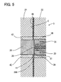
- Figure 5 shows a state in which the core section has moved forward and gate cutting is performed
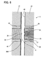
- Figure 6 shows a state in which after completion of gate cutting, mold opening is performed on the mold.
- the movable mold 21 is mold-clamped with respect to the fixed mold 22 substantially at the same time as this process.
- the core section 36 moves forward (rightward direction shown in Figure 5 ) via the ball screw mechanism 28, and as shown in Figure 5 , as the core section 36 moves forward, the nozzle receiving section 37 and the nozzle 20 are pressed and move backward, whereby gate cutting is performed.
- the movable mold 21 is mold-opened with respect to the fixed mold 22 and the molded molding product is ejected from the cavity C.
- shutting the end of the nozzle 20 with the protruding part 38 as shown in Figure 5 can suppress influences of inflow of melted resin supplied from the nozzle 20 on the screw 6 side and pressure propagation, reduce the amount of melted resin between the core section 36 and nozzle 20 before gate cutting, prevent cracking of the molding product due to remaining stress and the occurrence of micro cracks and cut burrs which may cause defective pasting of the molding product and consequently reduce the thickness of the remaining resin after gate cutting.
- the injection molding machine 1 is configured such that the end of the nozzle receiving section 37 configured on the fixed mold 22 side of the cavity C formed of the fixed mold 22 and the movable mold 21 is made to slightly protrude toward the movable mold 21, the movable mold 21 is provided with the core section 36 facing the nozzle receiving section 37 in a manner movable forward/backward, the end of the nozzle 20 is disposed on substantially the same plane as that of the end of the nozzle receiving section 37, the protruding part 38 is provided at the position of the core section 36 facing the end of the nozzle 20 that injects melted resin, gate cutting of the resin injected into the cavity C is performed by moving the core section 36 forward and causing the nozzle receiving section 37 and nozzle 20 pressed by the core section 36 that has moved forward to move backward, and a film of resin is made to remain at the ends of the nozzle receiving section 37 and nozzle 20 through gate cutting.
- the melted resin injected from the nozzle 20 is filled from the gate 41 into the cavity C, and when the core section 36 moves forward next, the forward movement of this core section 36 causes the nozzle receiving section 37 and nozzle 20 to be pressed and move backward, gate cutting is performed, and the movable mold 21 then moves backward and mold opening is performed.
- resin existing between the core section 36, nozzle receiving section 37 and nozzle 20 is cooled and solidified and united with resin filling the interior of the nozzle 20, thereby remains in a film-shape at the ends of the nozzle receiving section 37 and nozzle 20, and therefore by melting the remaining resin with heat of melted resin supplied from the nozzle 20 at the time of fillng resin into the cavity C in the next cycle and using the melted resin as resin to be filled into the cavity C, it is possible to use the resin as part of a molding product to be molded in the next molding cycle.
- the protruding part 38 is provided at the position of the core section 36 facing the end of the nozzle 20 that injects melted resin, by disposing the protruding part 38 so as to enter the nozzle 20 at the end thereof, it is possible to reduce cold slug remaining inside the nozzle 20 at the end thereof, which may cause appearance defects and adjust the film thickness of resin remaining at the ends of the nozzle receiving section 37 and the nozzle 20 to a predetermined thickness. Therefore, since resin can be made to remain in the nozzle receiving section 37 and nozzle 20 as a thin film, it is possible to prevent a variation in the thickness of the remaining resin layer from adversely influencing quality of the molding product as in the related art.
- the nozzle 20 is provided with a heater, when cooled, solidified remaining film-shaped resin is filled into the cavity C, by heating and melting the film-shaped melted resin using the heater provided for the nozzle 20, it is possible to smoothly fill the film-shaped resin together with the melted resin supplied through injection from the nozzle 20 into the cavity C. Therefore, the remaining film-shaped resin can be used as part of the molding product.
Landscapes
- Engineering & Computer Science (AREA)
- Manufacturing & Machinery (AREA)
- Mechanical Engineering (AREA)
- Moulds For Moulding Plastics Or The Like (AREA)
- Injection Moulding Of Plastics Or The Like (AREA)
Applications Claiming Priority (2)
| Application Number | Priority Date | Filing Date | Title |
|---|---|---|---|
| JP2006247351A JP4647568B2 (ja) | 2006-09-12 | 2006-09-12 | 射出成形機 |
| PCT/JP2007/066151 WO2008032533A1 (en) | 2006-09-12 | 2007-08-21 | Injection molding machine |
Publications (1)
| Publication Number | Publication Date |
|---|---|
| EP2062716A1 true EP2062716A1 (en) | 2009-05-27 |
Family
ID=39183598
Family Applications (1)
| Application Number | Title | Priority Date | Filing Date |
|---|---|---|---|
| EP07805952A Withdrawn EP2062716A1 (en) | 2006-09-12 | 2007-08-21 | Injection molding machine |
Country Status (7)
| Country | Link |
|---|---|
| US (1) | US8016588B2 (OSRAM) |
| EP (1) | EP2062716A1 (OSRAM) |
| JP (1) | JP4647568B2 (OSRAM) |
| KR (1) | KR20090060217A (OSRAM) |
| CN (1) | CN101505940B (OSRAM) |
| TW (1) | TW200827139A (OSRAM) |
| WO (1) | WO2008032533A1 (OSRAM) |
Family Cites Families (22)
| Publication number | Priority date | Publication date | Assignee | Title |
|---|---|---|---|---|
| US3989436A (en) * | 1975-12-18 | 1976-11-02 | Rca Corporation | Apparatus for producing injection molded and centrally apertured disc records |
| US4372741A (en) * | 1980-10-31 | 1983-02-08 | Discovision Associates | Hot sprue valve assembly for an injection molding machine |
| US4391579A (en) * | 1981-09-23 | 1983-07-05 | Discovision Associates | Hot sprue valve assembly for an injection molding machine |
| US4618466A (en) * | 1982-10-21 | 1986-10-21 | Apsley Metals Limited | Moulding apparatus |
| JP2642158B2 (ja) * | 1988-08-16 | 1997-08-20 | 住友重機械工業株式会社 | 光ディスク基板成形用金型 |
| JP2710254B2 (ja) * | 1989-11-01 | 1998-02-10 | 住友重機械工業株式会社 | フイルムゲートを金型内で剪断する射出成形金型 |
| EP0596413B1 (en) * | 1992-11-04 | 1998-12-16 | TDK Corporation | Method of making a plurality of optical record disc substrates, and an apparatus therefore |
| EP0614744B1 (en) * | 1993-02-25 | 1998-11-04 | Sony Electronics Inc. | Molding devices |
| JP2944359B2 (ja) * | 1993-03-23 | 1999-09-06 | 株式会社精工技研 | 基盤射出成形金型 |
| JP2800103B2 (ja) * | 1995-04-17 | 1998-09-21 | 日精樹脂工業株式会社 | ランナーレス金型 |
| JPH10154359A (ja) * | 1996-11-21 | 1998-06-09 | Matsushita Electric Ind Co Ltd | 薄肉部品の成形方法およびその装置 |
| US6002663A (en) * | 1997-04-17 | 1999-12-14 | Imation Corp. | Hubless optical disc having low radial runout and method of manufacture |
| CN2329505Y (zh) * | 1998-04-27 | 1999-07-21 | 李洲企业股份有限公司 | 具有自动裁切废料的模具 |
| HK1040957A1 (zh) * | 1998-09-18 | 2002-06-28 | 罗姆两合公司 | 用於信息載體盤毛坯的模具 |
| JP2002240101A (ja) * | 2000-12-15 | 2002-08-28 | Sony Corp | ディスク基板及びそれを射出成形する金型装置とディスク基板取出し用ロボット |
| JP2003053786A (ja) * | 2001-08-14 | 2003-02-26 | Sony Corp | 樹脂基板成型用射出成形装置 |
| KR100710727B1 (ko) * | 2002-11-18 | 2007-04-23 | 스미도모쥬기가이고교 가부시키가이샤 | 성형용 금형, 성형방법, 디스크기판 및 성형기 |
| WO2004078446A1 (ja) * | 2003-03-03 | 2004-09-16 | Matsushita Electric Industrial Co. Ltd. | ディスク基板成形用金型およびディスク基板の製造方法 |
| JP2005190632A (ja) * | 2003-12-26 | 2005-07-14 | Technos:Kk | ダイヤモンド様炭素膜を施した光ディスク成形金型とそれを使用する成形方法 |
| WO2005099992A1 (ja) * | 2004-03-31 | 2005-10-27 | Sumitomo Heavy Industries, Ltd. | ディスク成形用金型、成形品及び成形機 |
| JPWO2005099993A1 (ja) * | 2004-03-31 | 2007-08-16 | 住友重機械工業株式会社 | 金型装置、成形品、その成形方法、成形機及びブシュ |
| JP4593572B2 (ja) * | 2004-11-18 | 2010-12-08 | パナソニック株式会社 | 射出成形装置、射出成形方法及び射出成形金型 |
-
2006
- 2006-09-12 JP JP2006247351A patent/JP4647568B2/ja not_active Expired - Fee Related
-
2007
- 2007-08-10 TW TW096129754A patent/TW200827139A/zh not_active IP Right Cessation
- 2007-08-21 KR KR1020087031025A patent/KR20090060217A/ko not_active Withdrawn
- 2007-08-21 US US12/374,119 patent/US8016588B2/en not_active Expired - Fee Related
- 2007-08-21 EP EP07805952A patent/EP2062716A1/en not_active Withdrawn
- 2007-08-21 WO PCT/JP2007/066151 patent/WO2008032533A1/ja not_active Ceased
- 2007-08-21 CN CN2007800313837A patent/CN101505940B/zh not_active Expired - Fee Related
Non-Patent Citations (1)
| Title |
|---|
| See references of WO2008032533A1 * |
Also Published As
| Publication number | Publication date |
|---|---|
| WO2008032533A1 (en) | 2008-03-20 |
| KR20090060217A (ko) | 2009-06-11 |
| TW200827139A (en) | 2008-07-01 |
| CN101505940B (zh) | 2011-11-16 |
| TWI308885B (OSRAM) | 2009-04-21 |
| US20090169671A1 (en) | 2009-07-02 |
| US8016588B2 (en) | 2011-09-13 |
| CN101505940A (zh) | 2009-08-12 |
| JP2008068455A (ja) | 2008-03-27 |
| JP4647568B2 (ja) | 2011-03-09 |
Similar Documents
| Publication | Publication Date | Title |
|---|---|---|
| CN103358498A (zh) | 注射成型机 | |
| JP3427170B2 (ja) | 射出成形機 | |
| JP4261473B2 (ja) | 成形方法及び成形機 | |
| US20070184140A1 (en) | Injection molding machine | |
| JP6845683B2 (ja) | 射出成形機及び射出成形方法 | |
| US8016588B2 (en) | Injection molding machine | |
| JP3268491B2 (ja) | 射出成形機及び射出成形方法 | |
| JP5595446B2 (ja) | 金属射出成形機の金型装置 | |
| JP3160888B2 (ja) | 射出成形用金型装置 | |
| JP3712331B2 (ja) | コア圧縮射出成形機 | |
| US20090140446A1 (en) | Molding machine control apparatus and molding method for molding machine | |
| JP7610460B2 (ja) | 射出成形機の制御装置、射出成形機、射出成形システム及び、射出成形機の制御方法 | |
| JP5566015B2 (ja) | 射出成形金型 | |
| JP2014201041A (ja) | 射出成形機 | |
| JP4855794B2 (ja) | 射出成形方法及び射出成形機 | |
| JP4324113B2 (ja) | トグル式型締装置 | |
| JP3132605B2 (ja) | 射出成形方法 | |
| JP3996476B2 (ja) | エジェクタピンの突出し方法 | |
| JP2003311790A (ja) | 射出成形用金型装置と射出成形方法 | |
| JP2003077178A (ja) | 光ディスクおよびその製造方法およびその製造装置 | |
| JPH06226806A (ja) | 射出成形方法 | |
| JP2004090283A (ja) | 射出成形機の駆動装置 | |
| JP2006102999A (ja) | 射出成形方法とこれに用いる射出成形機 | |
| JPH1177773A (ja) | 射出成形機 | |
| JP2008238555A (ja) | 射出成形用金型及び射出成形品の製造方法 |
Legal Events
| Date | Code | Title | Description |
|---|---|---|---|
| PUAI | Public reference made under article 153(3) epc to a published international application that has entered the european phase |
Free format text: ORIGINAL CODE: 0009012 |
|
| 17P | Request for examination filed |
Effective date: 20090128 |
|
| AK | Designated contracting states |
Kind code of ref document: A1 Designated state(s): AT BE BG CH CY CZ DE DK EE ES FI FR GB GR HU IE IS IT LI LT LU LV MC MT NL PL PT RO SE SI SK TR |
|
| AX | Request for extension of the european patent |
Extension state: AL BA HR MK RS |
|
| STAA | Information on the status of an ep patent application or granted ep patent |
Free format text: STATUS: THE APPLICATION HAS BEEN WITHDRAWN |
|
| 18W | Application withdrawn |
Effective date: 20100730 |