EP2060929A1 - Procédé de détection de cible par radar et dispositif de radar utilisant le procédé de détection de cible - Google Patents
Procédé de détection de cible par radar et dispositif de radar utilisant le procédé de détection de cible Download PDFInfo
- Publication number
- EP2060929A1 EP2060929A1 EP07829690A EP07829690A EP2060929A1 EP 2060929 A1 EP2060929 A1 EP 2060929A1 EP 07829690 A EP07829690 A EP 07829690A EP 07829690 A EP07829690 A EP 07829690A EP 2060929 A1 EP2060929 A1 EP 2060929A1
- Authority
- EP
- European Patent Office
- Prior art keywords
- antenna elements
- target
- azimuth
- transmission
- antenna
- Prior art date
- Legal status (The legal status is an assumption and is not a legal conclusion. Google has not performed a legal analysis and makes no representation as to the accuracy of the status listed.)
- Withdrawn
Links
Images


Classifications
-
- G—PHYSICS
- G01—MEASURING; TESTING
- G01S—RADIO DIRECTION-FINDING; RADIO NAVIGATION; DETERMINING DISTANCE OR VELOCITY BY USE OF RADIO WAVES; LOCATING OR PRESENCE-DETECTING BY USE OF THE REFLECTION OR RERADIATION OF RADIO WAVES; ANALOGOUS ARRANGEMENTS USING OTHER WAVES
- G01S13/00—Systems using the reflection or reradiation of radio waves, e.g. radar systems; Analogous systems using reflection or reradiation of waves whose nature or wavelength is irrelevant or unspecified
- G01S13/02—Systems using reflection of radio waves, e.g. primary radar systems; Analogous systems
- G01S13/06—Systems determining position data of a target
- G01S13/42—Simultaneous measurement of distance and other co-ordinates
-
- G—PHYSICS
- G01—MEASURING; TESTING
- G01S—RADIO DIRECTION-FINDING; RADIO NAVIGATION; DETERMINING DISTANCE OR VELOCITY BY USE OF RADIO WAVES; LOCATING OR PRESENCE-DETECTING BY USE OF THE REFLECTION OR RERADIATION OF RADIO WAVES; ANALOGOUS ARRANGEMENTS USING OTHER WAVES
- G01S13/00—Systems using the reflection or reradiation of radio waves, e.g. radar systems; Analogous systems using reflection or reradiation of waves whose nature or wavelength is irrelevant or unspecified
- G01S13/02—Systems using reflection of radio waves, e.g. primary radar systems; Analogous systems
- G01S13/06—Systems determining position data of a target
- G01S13/08—Systems for measuring distance only
- G01S13/32—Systems for measuring distance only using transmission of continuous waves, whether amplitude-, frequency-, or phase-modulated, or unmodulated
- G01S13/34—Systems for measuring distance only using transmission of continuous waves, whether amplitude-, frequency-, or phase-modulated, or unmodulated using transmission of continuous, frequency-modulated waves while heterodyning the received signal, or a signal derived therefrom, with a locally-generated signal related to the contemporaneously transmitted signal
- G01S13/343—Systems for measuring distance only using transmission of continuous waves, whether amplitude-, frequency-, or phase-modulated, or unmodulated using transmission of continuous, frequency-modulated waves while heterodyning the received signal, or a signal derived therefrom, with a locally-generated signal related to the contemporaneously transmitted signal using sawtooth modulation
-
- G—PHYSICS
- G01—MEASURING; TESTING
- G01S—RADIO DIRECTION-FINDING; RADIO NAVIGATION; DETERMINING DISTANCE OR VELOCITY BY USE OF RADIO WAVES; LOCATING OR PRESENCE-DETECTING BY USE OF THE REFLECTION OR RERADIATION OF RADIO WAVES; ANALOGOUS ARRANGEMENTS USING OTHER WAVES
- G01S13/00—Systems using the reflection or reradiation of radio waves, e.g. radar systems; Analogous systems using reflection or reradiation of waves whose nature or wavelength is irrelevant or unspecified
- G01S13/02—Systems using reflection of radio waves, e.g. primary radar systems; Analogous systems
- G01S13/06—Systems determining position data of a target
- G01S13/08—Systems for measuring distance only
- G01S13/32—Systems for measuring distance only using transmission of continuous waves, whether amplitude-, frequency-, or phase-modulated, or unmodulated
- G01S13/34—Systems for measuring distance only using transmission of continuous waves, whether amplitude-, frequency-, or phase-modulated, or unmodulated using transmission of continuous, frequency-modulated waves while heterodyning the received signal, or a signal derived therefrom, with a locally-generated signal related to the contemporaneously transmitted signal
- G01S13/345—Systems for measuring distance only using transmission of continuous waves, whether amplitude-, frequency-, or phase-modulated, or unmodulated using transmission of continuous, frequency-modulated waves while heterodyning the received signal, or a signal derived therefrom, with a locally-generated signal related to the contemporaneously transmitted signal using triangular modulation
-
- G—PHYSICS
- G01—MEASURING; TESTING
- G01S—RADIO DIRECTION-FINDING; RADIO NAVIGATION; DETERMINING DISTANCE OR VELOCITY BY USE OF RADIO WAVES; LOCATING OR PRESENCE-DETECTING BY USE OF THE REFLECTION OR RERADIATION OF RADIO WAVES; ANALOGOUS ARRANGEMENTS USING OTHER WAVES
- G01S13/00—Systems using the reflection or reradiation of radio waves, e.g. radar systems; Analogous systems using reflection or reradiation of waves whose nature or wavelength is irrelevant or unspecified
- G01S13/02—Systems using reflection of radio waves, e.g. primary radar systems; Analogous systems
- G01S13/06—Systems determining position data of a target
- G01S13/46—Indirect determination of position data
-
- G—PHYSICS
- G01—MEASURING; TESTING
- G01S—RADIO DIRECTION-FINDING; RADIO NAVIGATION; DETERMINING DISTANCE OR VELOCITY BY USE OF RADIO WAVES; LOCATING OR PRESENCE-DETECTING BY USE OF THE REFLECTION OR RERADIATION OF RADIO WAVES; ANALOGOUS ARRANGEMENTS USING OTHER WAVES
- G01S13/00—Systems using the reflection or reradiation of radio waves, e.g. radar systems; Analogous systems using reflection or reradiation of waves whose nature or wavelength is irrelevant or unspecified
- G01S13/02—Systems using reflection of radio waves, e.g. primary radar systems; Analogous systems
- G01S13/50—Systems of measurement based on relative movement of target
- G01S13/58—Velocity or trajectory determination systems; Sense-of-movement determination systems
- G01S13/583—Velocity or trajectory determination systems; Sense-of-movement determination systems using transmission of continuous unmodulated waves, amplitude-, frequency-, or phase-modulated waves and based upon the Doppler effect resulting from movement of targets
-
- G—PHYSICS
- G01—MEASURING; TESTING
- G01S—RADIO DIRECTION-FINDING; RADIO NAVIGATION; DETERMINING DISTANCE OR VELOCITY BY USE OF RADIO WAVES; LOCATING OR PRESENCE-DETECTING BY USE OF THE REFLECTION OR RERADIATION OF RADIO WAVES; ANALOGOUS ARRANGEMENTS USING OTHER WAVES
- G01S13/00—Systems using the reflection or reradiation of radio waves, e.g. radar systems; Analogous systems using reflection or reradiation of waves whose nature or wavelength is irrelevant or unspecified
- G01S13/88—Radar or analogous systems specially adapted for specific applications
- G01S13/93—Radar or analogous systems specially adapted for specific applications for anti-collision purposes
- G01S13/931—Radar or analogous systems specially adapted for specific applications for anti-collision purposes of land vehicles
- G01S2013/9327—Sensor installation details
- G01S2013/93271—Sensor installation details in the front of the vehicles
Definitions
- the present invention relates to target detection methods for use in a radar, and in particular, to a method for detecting a relative velocity of a target and a radar device using the target detection method.
- radar devices that are mounted in, for example, the front side of a vehicle and that detects a target by transmitting a transmission wave to a predetermined detection area containing the front of the vehicle, receiving a reflected wave from the target within the detection area, and thus detecting the target.
- Many such radar devices employ the frequency modulated continuous-wave (FMCW) system in the vehicle field.
- FMCW frequency modulated continuous-wave
- an FMCW radar device uses a transmission signal having a triangular wave shape having alternate rising modulation sections at which the frequency of the transmission signal gradually increases and falling modulated sections at which the frequency of the transmission signal gradually decreases.
- the radar device calculates the beat frequency in the rising modulated section and the beat frequency in the falling modulated section.
- the beat frequency indicates the frequency in which the frequency of a transmission signal and the frequency of a reception signal responsive to that transmission signal are mixed.
- the radar device calculates the relative velocity of a target from the difference between the beat frequency in the rising modulated section and the beat frequency in the falling modulated section.
- Patent Documents 1 and 2 always have to calculate the beat frequency and the Doppler frequency to calculate the relative velocity, so processing is inevitably complex. Also, if a plurality of targets are present in a detection area, a plurality of spectrum peaks of the beat frequency exist and thus it is necessary to pair appropriate spectrums. Unfortunately, this pairing process may have an error. If an error occurs, it is difficult to accurately calculate the relative velocity.
- the present invention relates to a target detection method for use in a radar, the radar including a transmission antenna and a reception antenna, at least one of the transmission antenna and the reception antenna including a plurality of antenna elements arranged in a straight line, the target detection method switching the plurality of antenna elements arranged in the straight line in synchronization with a modulation cycle of a transmission signal, and to a radar device using the target detection method.
- the target detection method for use in a radar has a first measurement phase in which the plurality of antenna elements are switched at first time intervals on the basis of a preset predetermined switching pattern and a first azimuth of a target is calculated, and a second measurement phase in which the plurality of antenna elements are switched at second time intervals different from the first time intervals on the basis of the predetermined switching pattern and a second azimuth of the target is calculated.
- the target detection method includes calculating a relative velocity of the target on the basis of the first azimuth, the second azimuth, each of the first time intervals, each of the second time intervals, and spacing between the plurality of antenna elements.
- either one or both of a transmission antenna and a reception antenna include a plurality of antenna elements arranged in a straight line, and a target is detected while the antenna elements for performing transmission and reception are switched.
- a transmission/reception system includes a transmission antenna composed of a signal antenna element and a reception antenna in which a plurality of antenna elements are arranged in a straight line, a reflected wave based on a transmission wave from the transmission antenna is sequentially received by the antenna elements of the reception antenna whose switching is controlled, and a reception signal is generated.
- a transmission/reception system When a transmission/reception system includes a transmission antenna in which a plurality of antenna elements are arranged in a straight line and a reception antenna composed of a single antenna element, transmission waves are sequentially transmitted from the antenna elements of the transmission antenna whose switching is controlled, a reflected wave based on each transmission wave is received by the reception antenna, and a reception signal is generated.
- a transmission/reception system includes a transmission antenna and a reception antenna both of which include a plurality of antenna elements arranged in a straight line
- transmission waves are sequentially transmitted from the antenna elements of the transmission antenna whose switching is controlled
- reflected waves are sequentially received by the antenna elements of the reception antenna whose switching is controlled, thereby a reception signal is generated for each of combinations of the antenna elements of the transmission antenna and the antenna elements of the reception antenna.
- the amount of change in phase of a reception signal in each of the phases is different.
- azimuths obtained by, for example, the beamforming method in the phases are different.
- the difference between time intervals (interval time difference) in the phases, the difference between azimuths in the phases, the antenna elements, and the relative velocity have a specific relationship. From this relationship, the relative velocity is calculated. Accordingly, the relative velocity can be calculated without calculation of Doppler frequency. At this time, the use of the calculated azimuth enables the true azimuth of the target to be calculated simultaneously.
- the relative velocity V can be calculated by use of a simple expression, as specifically shown in expression (1).
- the target detection method for use in a radar according to the present invention may include setting the interval time difference ⁇ t between the first time interval and the second time interval such that the following expression is satisfied: ⁇ t ⁇ ⁇ / 2 ⁇ V max - V min where a possible relative velocity of the target to be detected is in a range of V min to V max , ⁇ t is the interval time difference between the first time interval and the second time interval, and ⁇ is a wavelength of a transmission/reception signal.
- the minimum value and the maximum value of the possible relative velocity of the target are set in advance as being V min and V max .
- the time difference of switching intervals of the antenna elements i.e., the interval time difference ⁇ t between the time interval in the first measurement phase and the time interval in the second measurement phase is determined.
- the interval time difference ⁇ t is determined in such a way, there is one candidate within the range of V min to V max among candidates for the relative velocity. Accordingly, the relative velocity whose measurement is desired can be measured with reliability.
- the target detection method for use in a radar according to the present invention may include setting the spacing between the antenna elements such that the following expression is satisfied: d ⁇ ⁇ / sin ⁇ max - sin ⁇ min where a direction perpendicular to an arrangement direction in which the plurality of antenna elements are arranged adjacent to a radiation direction of the transmission signal is 0° direction, a detection azimuth angle range of ⁇ min to ⁇ max extending from the 0° direction to the arrangement direction is set within a range of -90° to +90°, d is the spacing between the plurality of antenna elements, and ⁇ is a wavelength of a transmission/reception signal.
- the azimuth angle range for use in target detection is set in advance as being ⁇ min to ⁇ max .
- the spacing d between the plurality of antenna elements is determined.
- each of the first azimuth and the second azimuth for use in calculation of the relative velocity is uniquely determined, so the relative velocity can be calculated with reliability.
- the target detection method for use in a radar according to the present invention may include, when the spacing d between the plurality of antenna elements is set as being smaller than 0.5 ⁇ with respect to the wavelength ⁇ of the transmission/reception signal, virtually setting the spacing d between the plurality of antenna elements at 0.5 ⁇ or more in calculating each azimuth to calculate a virtual azimuth, and correcting the calculated azimuth so as to correspond to the state in which the spacing d between the plurality of antenna elements is set as being smaller than 0.5 ⁇ to calculate the azimuth.
- the inter-antenna element spacing d is smaller than 0.5 ⁇ , the range of a possible phase difference between the antenna elements caused by the true azimuth of the target is narrower than - ⁇ /2 to + ⁇ /2.
- an observation peak that should appear is absent in any of the azimuth even when computation of calculation of the arrival angle is performed. That is, it is difficult to calculate the accurate azimuth in actuality from the above expressions unless the inter-antenna element spacing d is at or above 0.5 ⁇ .
- the inter-antenna element spacing d is virtually set as being at or above 0.5 ⁇ in calculation of the detection azimuth, and the first azimuth and the second azimuth are calculated by the above-described method. Then, from the relationship between the set value of the inter-antenna element spacing in the calculation of the detection azimuth and the actual inter-antenna element spacing, the calculated first azimuth and second azimuth are corrected. This enables the actual first azimuth and second azimuth to be calculated, and together with this, the relative velocity is also calculated.
- the plurality of antenna elements are arranged at unequal intervals, and the greatest common divisor of the unequal intervals is matched to the spacing d.
- the use of the unequal intervals at which the antenna elements are arranged extends the spacing at both ends of the antenna elements arranged and improves the azimuth resolution. Accordingly, the spectrum peak is more acute, and the first azimuth and the second azimuth are calculated with higher precision, and thus, the relative velocity is calculated with higher precision.
- the target detection method for use in a radar according to the present invention may include setting the interval time difference ⁇ t between the first time interval and the second time interval in a variable manner.
- the relative velocity can be readily calculated using only simple computation without complex computation, such as calculation of Doppler frequency.
- the azimuth can also be calculated substantially simultaneously using the same processing system.
- the relative velocity of the target can be calculated with reliability and high precision by appropriate settings of the inter-antenna spacing and the detection azimuth angle range.
- the load on computation of the relative velocity can be reduced by appropriate setting of the calculation azimuth angle range.
- the relative velocity of the target can be detected with higher precision by setting of the inter-antenna spacing at unequal intervals.
- the relative velocities of a plurality of targets can be detected at the same time.
- an FMCW radar device including a transmission antenna composed of a single antenna element and a reception antenna made up of a plurality of antenna elements is illustrated by way of example.
- an FMCW radar device that uses a transmission signal modulated so as to have a triangular wave form having a rising modulated section at which the frequency gradually increases and a falling modulated section at which the frequency gradually decreases is illustrated by way of example.
- the configuration and processing described below are also applicable to a radar device that has only rising modulation or falling modulation.
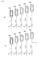
- Fig. 1 is a block diagram that illustrates a schematic configuration of the FMCW radar device according to the present embodiment.
- the radar device according to the present embodiment includes a signal processor 1 performing transmission-signal control, switching control, and target detection, an RF module 2, a transmission antenna 40, and a reception antenna 50.
- the signal processor 1 generates a transmission control signal and a switching control signal as a transmission system control.
- the transmission control signal is a signal to be supplied to a VCO 21 of the RF module 2 in order to chronologically generate a transmission signal modulated so as to have a triangular form (hereinafter referred to simply as "triangular modulated transmission signal").
- the switching control signal is a signal to be supplied to an output switching circuit 23 of the RF module 2 in order to select one of antenna elements 51 to 55 of the reception antenna 50.
- the signal processor 1 outputs a transmission control signal such that a transmission signal is generated in a first measurement phase and a second measurement phase having different transmission cycles.
- a generated triangular modulated transmission signal is composed of triangular modulated sections, in which a signal is modulated so as to have a triangular form, and unmodulated sections between the triangular modulated sections.
- the time length of each of the triangular modulated sections in the first measurement phase is set to be equal to that in the second measurement phase.
- the time length of each of the unmodulated sections in the second measurement phase is set to be longer than that in the first measurement phase.
- Fig. 2 is an illustration that shows a synchronization state between transmission control and switching control; (A) illustrates a first measurement phase in which the antenna element is switched with a switching time T 1 and (B) illustrates a second measurement phase in which the antenna element is switched with a switching time T 2 .
- the signal processor 1 outputs a switching control signal matching a rising timing in each of triangular modulated sections with a switching timing for the antenna elements 51 to 55 such that the antenna elements 51 to 55 are sequentially associated with the triangular modulated sections.
- a switching pattern for the antenna elements 51 to 55 is composed of a preset pattern that is the same in the first measurement phase and the second measurement phase. For example, as illustrated in Fig. 2 , a switching pattern that repeats, in chronological order, from the antenna element 51 to the antenna element 52 to the antenna element 53 to the antenna element 54 to the antenna element 55 is used.
- the transmission pattern of the transmission signal and the switching pattern for the antenna elements are not limited to the above examples. They may be various repeating patterns described in the end of the description of the embodiments in this specification.
- the RF module 2 includes the VCO 21 and a distributor 22 as transmission system circuitry and also includes the output switching circuit 23, an RF amplifier 24, a mixer 25, and an intermediate-frequency (IF) amplifier 26 as reception system circuitry.
- the VCO 21 serving as the transmission system circuitry of the RF module 2 is made up of what is called a voltage-controlled oscillator.
- the VCO 21 generates a triangular modulated transmission signal in response to a transmission control signal from the signal processor 1 and output it to the distributor 22.
- the distributor 22 is composed of a directional coupler.
- the distributor 22 supplies a triangular modulated transmission signal output from the VCO 21 to the transmission antenna 40 and also generates a local signal in which the power of the triangular modulated transmission signal is distributed and supplies it to the mixer 25.
- the transmission antenna 40 is composed of, for example, a single patch antenna and emits a transmission wave in which a triangular modulated transmission signal is converted into a radio wave into a detection area.
- the reception antenna 50 includes the antenna elements 51 to 55.
- Each of the antenna elements 51 to 55 is composed of, for example, a patch antenna and is composed of, for example, a plurality of patch electrodes arranged in a straight line at regular intervals on a dielectric substrate.
- the direction in which the antenna elements 51 to 55 are arranged is perpendicular to the direction of the front of the radar device (the direction of the front of a vehicle in which the radar device is mounted) and arranged along the horizontal direction. In the present embodiment, a more specific positional relationship is provided in which the antenna elements 51, 52, 53, 54, and 55 are arranged in sequence from the right end to the left end viewed from the front of the radar device.
- Each of the antenna elements 51 to 55 of the reception antenna 50 receives, for example, a reflection wave from a target based on a transmission wave, generates a reception signal, and outputs it to the output switching circuit 23 of the RF module 2.
- the output switching circuit 23 serving as the reception system of the RF module 2 receives a reception signal from each of the antenna elements 51 to 55.
- the output switching circuit 23 has a supplied switching control signal, which is previously described, and switches connection between the RF amplifier 24 and one of the antenna elements 51 to 55 in accordance with that switching control signal. That is, the reception signal from an antenna element selected in accordance with the switching control signal is supplied to the RF amplifier 24.
- switching the antenna elements is performed according to the transmission cycle T 1 in a first measurement phase and according to the transmission cycle T 2 in a second measurement phase.
- a reception signal of an antenna element output for each of the above-described triangular modulated sections is supplied to the RF amplifier 24.
- the RF amplifier 24 performs gain control on a supplied reception signal and outputs an RF signal acquired by the gain control to the mixer 25.
- the mixer 25 the RF signal and a local signal together to generate an IF beat signal and supplies the IF beat signal to the IF amplifier 26.
- the IF amplifier 26 performs gain control on the IF beat signal and outputs it to an A/D converter 3.
- the A/D converter 3 samples the IF beat signal amplified (subjected to the gain control) at a predetermined sampling cycle, thereby converting the analog IF beat signal into a digital IF beat signal.
- the A/D converter 3 outputs the digital IF beat signal to the signal processor 1.
- a buffer memory 10 serving as the reception system of the signal processor 1 sequentially buffers an input IF beat signal. At this time, the IF beat signal is buffered in the buffer memory 10 in units of measurement phases.
- a Fourier transform processing portion 11 includes a temporal Fourier transform processing section 111 and a beam forming section 112.
- the temporal Fourier transform processing section 111 generates a frequency spectrum using known fast Fourier transform (FFT) and supplies it to a distance/relative velocity detecting portion 12.
- the beam forming section 112 generates a directional spectrum by the Capon method or Beamformer method using the frequency spectrum and supplies it to an azimuth detecting portion 13. At this time, the Fourier transform processing portion 11 generates the directional spectrum in units of measurement phases.
- the distance/relative velocity detecting portion 12 calculates a relative velocity of a target to be detected with respect to the radar device using a method described below.
- the radar device detects a relative velocity of a target on the basis of the principle below.
- Figs. 3 to 7 are illustrations for describing the principle of detection of the relative velocity of a target.
- Fig. 3 illustrates a change in distance to the target in accordance with the relative velocity.
- d represents the distance between the antenna elements
- r 0 represents the distance between a target 900 and the antenna element 51 when an output of the reception signal of the antenna element 51 is selected
- r represents the amount of change in distance in accordance with the relative velocity according to an antennal switching cycle.
- the distance for selection of the antenna element 51 is r 0
- the distance for selection of the antenna element 52 is r 0 + r
- the distance for selection of the antenna element 53 is r 0 + 2r
- the distance for selection of the antenna element 54 is r 0 + 3r
- the distance for selection of the antenna element 55 is r 0 + 4r.
- Fig. 4(A) is an illustration that shows a change in distance to the target in accordance with the relative velocity in a first measurement phase
- Fig. 4(B) is an illustration that shows a change in distance to the target in accordance with the relative velocity in a second measurement phase.
- the distance in the first measurement phase, the distance varies on an r 1 basis according to the transmission cycle T 1 .
- the distance for selection of the antenna element 51 is r 0
- the distance for selection of the antenna element 52 is r 0 + r 1
- the distance for selection of the antenna element 53 is r 0 + 2r 1
- the distance for selection of the antenna element 54 is r 0 + 3r 1
- the distance for selection of the antenna element 55 is r 0 + 4r 1 .
- the distance varies on an r 2 basis according to the transmission cycle T 2 .
- the distance for selection of the antenna element 51 is r 0
- the distance for selection of the antenna element 52 is r 0 + r 2
- the distance for selection of the antenna element 53 is r 0 + 2r 2
- the distance for selection of the antenna element 54 is r 0 + 3r 2
- the distance for selection of the antenna element 55 is r 0 + 4r 2 .
- r 2 r 1 + ⁇ r, where ⁇ r is the difference in distance according to the difference ⁇ t in time length between the transmission cycles T 1 and T 2 .
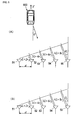
- Fig. 5(A) is an illustration that shows a change in a round-trip distance from the radar device to the target in a first measurement phase.
- Fig. 5(B) is an illustration that shows a change in a round-trip distance from the radar device to the target in a first measurement phase.
- a first measurement phase when the distance from the antenna element 51 to a virtual phase reference plane is "0," the distances from the antenna elements 52, 53, 54, and 55 to the virtual phase reference plane are L + 2r 1 , 2L + 4r 1 , 3L + 6r 1 , and 4L + 8r 1 , respectively.
- L is the change in distance in accordance with the azimuth ⁇ of the target
- 2r 1 is the change in distance in accordance with the velocity V of the target.
- a second measurement phase subsequent to the first measurement phase when the distance from the antenna element 51 to a virtual phase reference plane is "0," the distances from the antenna elements 52, 53, 54, and 55 to the virtual phase reference plane are L + 2r 2 , 2L + 4r 2 , 3L + 6r 2 , and 4L + 8r 2 , respectively.
- L is the change in distance in accordance with the azimuth ⁇ of the target
- 2r 2 is the change in distance in accordance with the velocity V of the target.
- This relationship provides, where a first azimuth calculated in the first measurement phase is ⁇ 1 , a second azimuth calculated in the second measurement phase is ⁇ 2 , the true azimuth unaffected by the relative velocity is ⁇ , a shift in azimuth in the first measurement phase with respect to the true azimuth ⁇ is ⁇ r1 , and a shift in azimuth in the second measurement phase with respect to the true azimuth ⁇ is ⁇ r2 , two expressions given below.
- This expression (7) is, that is, the first term itself in the right-hand side of the previously described expression (1), which represents a relative-velocity candidate V. Performing this computation enables the relative-velocity candidate V of the target to be calculated.
- the signal processor 1 calculates the above relative-velocity candidate V using a process flow described below.
- the signal processor 1 calculates a directional spectrum from a group of reception signals in a first measurement phase and calculates the sine value sin ⁇ 1 for the azimuth angle ⁇ 1 .
- the signal processor 1 calculates a directional spectrum from a group of reception signals in a second measurement phase subsequent to the first measurement phase and calculates the sine value sin ⁇ 2 for the azimuth angle ⁇ 2 .
- the signal processor 1 applies the calculated sin ⁇ 1 and sin ⁇ 2 in expression (1), thereby calculating the relative-velocity candidate V.
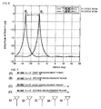
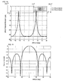
- Fig. 6 illustrates the directional spectrum in accordance with a reception signal in the above-described first measurement phase and the directional spectrum in accordance with a reception signal in the above-described second measurement phase.
- T 1 cycle scan in the drawings represents behavior in the first measurement phase
- T 2 cycle scan in the drawings represents behavior in the second measurement phase.
- the azimuth ⁇ 1 in the first measurement phase at which the antenna elements 51, 52, 53, 54, and 55 are sequentially selected at the switching cycle T 1 is -5.00°
- the use of the configuration and the processing according to the present embodiment enables the relative velocity of the target to be accurately detected with reliability without the performance of complex processing, such as calculation of a Doppler frequency of the target. Also, because processing operation is simple, the high-precision detection can be made at high speed.
- the first measurement phase and the second measurement phase are formed using all of the antenna elements 51 to 55 consisting of the reception antenna. However, it is not necessarily required to switch all of the antenna elements from one end to the other end in antenna arrangement. As illustrated in Fig. 7 , a pattern in which a part of the antenna elements are switched may be used.
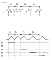
- Fig. 7 is an illustration that shows a switching pattern for each switching mode of the antenna elements; (A) and (B) illustrate a high-speed detection mode and (C) and (D) illustrate a normal detection mode.
- the signal processor 1 has the function of switching mode.
- the signal processor 1 switches the mode, for example, in response to an input from operation of a user.
- the mode can include, for example, a high-speed detection mode in which the relative velocity is detected at high speed and a normal detection mode in which the relative velocity is detected in a normal detection time.
- the signal processor 1 detects the relative velocity from the first measurement phase illustrated in Fig. 7(A) and the second measurement phase illustrated in Fig. 7(B) . That is, first, for the first measurement phase, the three antenna elements 51 to 53 are switched at the switching cycle T 1 , and the first azimuth ⁇ 1 is calculated.
- the three antenna elements 51 to 53 are switched at the switching cycle T 2 , and the second azimuth ⁇ 2 is calculated. Then, the relative velocity V is calculated using these first azimuth ⁇ 1 and second azimuth ⁇ 2 . With this process, because the number of switched antenna elements is small, the relative velocity can be detected faster than that in the normal detection mode.
- the signal processor 1 When receiving selection of the normal detection mode, the signal processor 1 detects the relative velocity from the first measurement phase illustrated in Fig. 7(C) and the second measurement phase illustrated in Fig. 7(D) . That is, first, for the first measurement phase, all of the antenna elements 51 to 55 are switched at the switching cycle T 1 , and the first azimuth ⁇ 1 is calculated. After that, for the second measurement phase, all of the antenna elements 51 to 55 are switched at the switching cycle T 2 , and the second azimuth ⁇ 2 is calculated. Then, the relative velocity V is calculated using these first azimuth ⁇ 1 and second azimuth ⁇ 2 . With this process, because the number of switched antenna elements is larger that that in the high-speed detection mode, the relative velocity can be detected more accurately than that in the high-speed detection mode.
- the time range of the switching interval difference ⁇ t for the antenna elements is not specified.
- the difference ⁇ t in switching interval can be set by the method described below.
- the relative-velocity candidate V appearing in the range of the possible relative velocity of the target is unique. Accordingly, the relative velocity can be calculated without ambiguity.
- the difference ⁇ r in distance to the time difference (switching interval difference) ⁇ t between the switching cycle T 1 for the first measurement phase and the switching cycle T 2 for the second measurement phase also becomes large.
- the phase difference according to the round-trip distance difference 2 ⁇ r occurs between the first measurement phase and the second measurement phase.
- the relative-velocity candidate V appear at intervals of ⁇ /(2 ⁇ t). Therefore, where the maximum relative-velocity candidate in the range of candidates of the relative velocity V is V max and the minimum relative-velocity candidate is V min , the relative-velocity candidate is uniquely determined in the case where the following condition is satisfied.
- the relative velocity can be uniquely calculated more reliably by use of the switching interval difference ⁇ t given by:
- V prv the relative velocity of the target obtained in the previous measurement
- ⁇ the maximum acceleration possible in nature of motion of the target
- ⁇ the deceleration
- - ⁇ the time difference between the previous measurement and the current measurement path
- V prv + ⁇ and V prv - ⁇ the maximum value V max of the velocity of the target possible at the time of the current measurement and the minimum value V min thereof. Accordingly, the following expression can be established.
- the inter-antenna element spacing d is at or above 0.5 ⁇ , the relative velocity and azimuth of the target can be detected with reliability.
- the detection range of the distance difference occurring between the neighboring antenna elements is -d + n ⁇ to +d + n ⁇ (n is an integer).
- the detection range of the distance difference is -0.4 ⁇ + n ⁇ to 0.4 ⁇ + n ⁇ .
- the switching cycle T 1 in a first measurement phase is 1 msec
- the switching cycle T 2 in a second measurement phase is 1.05 msec
- the relative velocity of the target is 2 km/h
- the distance difference between the neighboring antenna elements is 0.32 ⁇ .
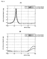
- the spectrum peak is obtainable (see Fig. 8(A) ) and the relative velocity is detectable.
- the detection range of the distance difference between the neighboring antenna elements is (-0.8 + n) ⁇ to (0.8 + n) ⁇ .
- setting the inter-antenna element spacing d at 0.5 ⁇ or more enables the spectrum peak in the azimuth direction to be reliably obtained, and the relative velocity of the target is detectable.
- the spectrum peak is reliably and readily obtainable by setting the inter-antenna element spacing d at 0.5 ⁇ or more.
- the spectrum peak is also obtainable by virtually setting the inter-antenna element spacing d in terms of arithmetic of the Capon method or the Beamformer method.
- the Beamformer method or other methods, a mode vector described below is used in the operation of an estimated arrival bearing.
- ⁇ ( ⁇ ) represents the mode vector to the estimated azimuth ⁇ and d1 to dk represent the spacing from one of the antenna elements that is set as the reference position to the other antenna elements, where the number of the antenna elements is k + 1.
- the inter-antenna element spacing d is below 0.5 ⁇ , the virtually set inter-antenna element spacing d' is used without the use of the actual inter-antenna element spacing d in d1 to dk in (Expression A).
- the directional spectrum illustrated in Fig. 9 is the one obtained under the same condition as that for the directional spectrum illustrated in Fig. 8(B) . That is, Fig. 9(A) and Fig. 8(B) illustrate the same result.
- the spectrum peak is obtainable by virtually setting the inter-antenna element spacing at 0.5 ⁇ or more without being affected by the relative velocity.
- the azimuth ⁇ 1 ' in the first measurement phase and the azimuth ⁇ 2 ' in the second measurement phase in such a way are different from the actual azimuth ⁇ .
- the relative velocity V can be calculated using the calculated azimuths ⁇ 1 and ⁇ 2 in the measurement phases.
- the radar device according to the present embodiment is the same as that of the radar device according to the first embodiment, except for the inter-antenna element spacing d.
- the true azimuth ⁇ of the target is calculated, as well as the relative velocity V of the target.
- a method for calculating the true azimuth ⁇ is specifically described below.
- the distance difference r caused by the relative velocity between the neighboring antenna elements is also increased.
- the distance difference r caused by the relative velocity is within the range of - ⁇ /2 to + ⁇ /2, there are no ambiguities.
- the distance difference r caused by the relative velocity is outside the range of - ⁇ /2 to + ⁇ /2, it is difficult to discriminate between r and r + n ⁇ (n is an integer).
- expression (12) reveals that a candidate for the sine value sin ⁇ of the true azimuth ⁇ is present at intervals of ⁇ /d.
- the unique candidate can be determined, so the true azimuth can be identified.
- the true azimuth ⁇ can be calculated reliably and readily by setting the inter-antenna element spacing d at a value that satisfies the following expression:
- the relative velocity V can be calculated by the performance of the operation described in the above embodiment using sin ⁇ 1 and sin ⁇ 2 used in the calculation of the true azimuth ⁇ .
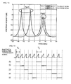
- Fig. 10 illustrates one example of a directional spectrum obtained by the configuration and processing according to the present embodiment.
- a transmission/reception beam pattern that has directional characteristics illustrated in Fig. 11 is formed.
- Fig. 11 is an illustration that shows the transmission/reception beam pattern according to the present embodiment.
- the transmission/reception beam pattern like this can be set by the configuration of the transmission antenna and the reception antenna and transmission and reception control.
- the use of the inter-antenna element spacing d in the present embodiment results in the presence of only one value within the range of ⁇ max to ⁇ min among values of ⁇ obtained by substitution of the first azimuth ⁇ 1 in the first measurement phase into expression (12).
- the relative velocity candidate V can be calculated using previously described expression (1) from sin ⁇ 1 and sin ⁇ 2 .
- the configuration and the performance of the processing according to the present embodiment enables the relative velocity of the target to be accurately detected with reliability.
- the detection range is set as being ⁇ min to ⁇ max . If the detection range is set as being the same range from the previously described 0° direction used as the center in both the positive and negative directions of the angle, the following expression
- a radar device and a method for detecting a target for use in a radar device according to a third embodiment are described with reference to the drawings.
- spacing between the antenna elements is not uniform.
- the other configuration thereof is the same as that of the radar device according to each of the first and second embodiments.
- Fig. 12(A) is an illustration that shows spacing between the antenna elements;
- Fig. 12(B) is an illustration that shows a synchronization state between transmission control and switching control.
- the spacings between the neighboring antenna elements of the antenna elements 51 to 55 are 2d, 2d, 3d, and 3d in sequence from the antenna element 51.
- the interval between the occurrences of grating lobes is determined by the greatest common divisor of the inter-antenna element spacings. Therefore, from the conditions described in the above first and second embodiments, when d is determined such that the following expression, the relative velocity V and true azimuth ⁇ can be uniquely determined.
- ⁇ can be calculated from expression (B) using the previously described virtual spacing d' (d' > 0.5 ⁇ ) in exactly the same manner, and then the relative velocity V can be uniquely determined.
- a radar device and a method for detecting a target for use in a radar device according to a fourth embodiment are described.
- the range of an azimuth computational angle estimated (estimated computational azimuth angle range) is set.
- the other configuration thereof is the same as that of the radar device according to the third embodiment.
- the maximum computational azimuth angle ⁇ cal is set as the following expression.
- ⁇ cal sin -1 ⁇ / 2 ⁇ d
- each of the first azimuth ⁇ 1 in the first measurement phase and the second azimuth ⁇ 2 in the second measurement phase has one spectrum peak. Therefore, the relative velocity V and the true azimuth ⁇ can be calculated readily and reliably.
- the estimated azimuth angle range can be substantially narrower than that in the above embodiments. Accordingly, the load on computation in calculation of the relative velocity and the azimuth can be reduced.
- the present embodiment does not relate to processing for one target, as described in the above embodiments, but relates to processing for the case where there are a plurality of targets within the detection range at substantially the same distance from the device itself.
- Fig. 13 is an illustration that shows directional spectrums when a plurality of targets exist at the same distance in different azimuths and have different relative velocities.
- the level of the spectrum peak in accordance with a reception signal in a first measurement phase and that in a second measurement phase are substantially the same if the same target (single target) is to be detected. Therefore, the level of the spectrum peak varies from one target to another, and the level of the spectrum peak for the same target in the first measurement phase and that in the second measurement phase are substantially the same.
- the signal processor 1 pairs the spectrum peak in the first measurement phase and the spectrum peak in the second measurement phase on the basis of the peak level from the spectrum peaks.
- the signal processor 1 detects the relative velocity and the true azimuth for each target using the paired spectrum peak in the first measurement phase and spectrum peak in the second measurement phase by a variety of methods previously described. Even when there are a plurality of targets having different relative velocities and azimuths at the same distance from the device, the use of such a processing method enables the relative velocities and azimuths to be detected with reliability and high precision.
- the spectrum peaks to be paired may also be determined by reduction in the interval time difference ⁇ t by the method described below utilizing the fact that the phase difference between the first measurement phase and the second measurement phase is 2V ⁇ t/ ⁇ .
- the upper limit of a possible relative velocity of the target is V max and the lower limit thereof is V min .
- the phase difference does not exceed 2 ⁇ , from expression (1), with respect to the first azimuth ⁇ 1 , it is necessary to detect ⁇ 2 such that the limit value sin ⁇ 2 is within the range given below.
- pairing can be performed with reliability by setting the interval time difference ⁇ s such that it gradually reduces to narrow down to one candidate for ⁇ 2 .
- the antenna elements are switched in the order of 51, 52, 53, 54, and 55 at the switching cycle T 1 in a first measurement phase, and the antenna elements are switched in the order of 51, 52, 53, 54, and 55 at the switching cycle T 2 in a second measurement phase.
- Figs. 14 to 17 are illustrations that show other transmission signal waveforms and a synchronization state between transmission control and switching control.
- Fig. 14 illustrates the case where a modulated signal having only a rising modulated section, what is called, a sawtooth waveform is used.
- the waveforms in the modulated sections are the same, whereas the length of unmodulated sections in a first measurement phase and that in a second measurement phase are different.
- Fig. 15 illustrates the case where a triangular modulated signal is used. There are no unmodulated sections in a first measurement phase, whereas there are unmodulated sections in a second measurement phase.
- Fig. 16 illustrates the case where a sawtooth modulated signal is used. There are two modulated sections in a single transmission cycle. The interval between the two modulated sections in the single transmission cycle varies from one transmission cycle to another.
- the first measurement phase consists of a sawtooth modulated signal corresponding to an initial (first) modulated section in a transmission cycle where each of the antenna elements 51 to 55 receives a signal
- the second measurement phase consists of a sawtooth modulated signal corresponding to a second modulated section in the transmission cycle where each of the antenna elements 51 to 55 receives a signal.
- Fig. 17 illustrates the case where a triangular modulated signal that has a rising modulated section and a falling modulated section is used.
- the triangular modulated signal has a non-modulated section between the rising modulated section and the falling modulated section.
- the non-modulated section varies from one triangular modulated signal to another.
- the first measurement phase consists of a signal in a rising modulated section in a triangular modulated signal received by each of the antenna elements 51 to 55
- the second measurement phase consists of a signal in a falling modulated section in the triangular modulated signal received by each of the antenna elements 51 to 55.
- the reception antenna is an array antenna in which a plurality of antenna elements are arranged by way of example.
- the transmission antenna may be the array antenna, or alternatively, each of the transmission antenna and the reception antenna may be the array antenna.
Landscapes
- Engineering & Computer Science (AREA)
- Radar, Positioning & Navigation (AREA)
- Remote Sensing (AREA)
- Physics & Mathematics (AREA)
- Computer Networks & Wireless Communication (AREA)
- General Physics & Mathematics (AREA)
- Electromagnetism (AREA)
- Signal Processing (AREA)
- Radar Systems Or Details Thereof (AREA)
Applications Claiming Priority (2)
| Application Number | Priority Date | Filing Date | Title |
|---|---|---|---|
| JP2006297475 | 2006-11-01 | ||
| PCT/JP2007/069954 WO2008053685A1 (fr) | 2006-11-01 | 2007-10-12 | Procédé de détection de cible par radar et dispositif de radar utilisant le procédé de détection de cible |
Publications (2)
| Publication Number | Publication Date |
|---|---|
| EP2060929A1 true EP2060929A1 (fr) | 2009-05-20 |
| EP2060929A4 EP2060929A4 (fr) | 2013-03-06 |
Family
ID=39344032
Family Applications (1)
| Application Number | Title | Priority Date | Filing Date |
|---|---|---|---|
| EP07829690A Withdrawn EP2060929A4 (fr) | 2006-11-01 | 2007-10-12 | Procédé de détection de cible par radar et dispositif de radar utilisant le procédé de détection de cible |
Country Status (4)
| Country | Link |
|---|---|
| US (1) | US7928897B2 (fr) |
| EP (1) | EP2060929A4 (fr) |
| JP (1) | JP4905457B2 (fr) |
| WO (1) | WO2008053685A1 (fr) |
Cited By (4)
| Publication number | Priority date | Publication date | Assignee | Title |
|---|---|---|---|---|
| WO2011032745A1 (fr) | 2009-09-16 | 2011-03-24 | Robert Bosch Gmbh | Dispositif détecteur de radar muni d'au moins un agencement d'antennes planaire |
| WO2014206630A1 (fr) * | 2013-06-25 | 2014-12-31 | Robert Bosch Gmbh | Détecteur à radar fmcw à résolution angulaire |
| WO2015197226A1 (fr) * | 2014-06-26 | 2015-12-30 | Robert Bosch Gmbh | Procédé de mesure par radar mimo |
| WO2015197223A1 (fr) * | 2014-06-26 | 2015-12-30 | Robert Bosch Gmbh | Procédé de mesure par radar à couvertures différentes |
Families Citing this family (31)
| Publication number | Priority date | Publication date | Assignee | Title |
|---|---|---|---|---|
| US7688253B2 (en) * | 2008-07-09 | 2010-03-30 | Honeywell International Inc. | Method and processor for reduced ambiguity resolution matrix for interferometric angle determination |
| US20100118033A1 (en) * | 2008-11-10 | 2010-05-13 | Vistaprint Technologies Limited | Synchronizing animation to a repetitive beat source |
| DE102009002243A1 (de) * | 2009-04-07 | 2010-10-14 | Robert Bosch Gmbh | FMCW-Radarsensor und Verfahren zum Frequenzmatching |
| JP5264606B2 (ja) * | 2009-04-22 | 2013-08-14 | 三菱電機株式会社 | レーダ装置 |
| DE102009027003A1 (de) * | 2009-06-17 | 2010-12-23 | Endress + Hauser Gmbh + Co. Kg | Optimierung der Schaltreihenfolge bei geschalteten Antennenarrays |
| JP2011013056A (ja) * | 2009-07-01 | 2011-01-20 | Toyota Central R&D Labs Inc | レーダ装置 |
| JP5655516B2 (ja) * | 2010-11-12 | 2015-01-21 | 株式会社デンソー | レーダ装置 |
| JP5653726B2 (ja) * | 2010-11-12 | 2015-01-14 | 株式会社デンソー | レーダ装置 |
| JP5677830B2 (ja) * | 2010-12-22 | 2015-02-25 | 日本電産エレシス株式会社 | 電子走査型レーダ装置、受信波方向推定方法及び受信波方向推定プログラム |
| JP5628732B2 (ja) * | 2011-04-04 | 2014-11-19 | 富士通テン株式会社 | レーダ装置用の演算装置、レーダ装置、レーダ装置用の演算方法およびプログラム |
| JP5721578B2 (ja) * | 2011-07-22 | 2015-05-20 | 三菱電機株式会社 | レーダ装置 |
| US20130088393A1 (en) * | 2011-10-06 | 2013-04-11 | Toyota Motor Engineering & Manufacturing North America, Inc. | Transmit and receive phased array for automotive radar improvement |
| US8941536B2 (en) * | 2011-11-01 | 2015-01-27 | The Charles Stark Draper Laboratory, Inc. | Short-range homodyne radar system |
| US8937570B2 (en) * | 2012-09-28 | 2015-01-20 | Battelle Memorial Institute | Apparatus for synthetic imaging of an object |
| JP6205729B2 (ja) | 2013-01-21 | 2017-10-04 | 株式会社デンソー | レーダ装置 |
| JP6338871B2 (ja) * | 2014-01-31 | 2018-06-06 | 株式会社デンソーテン | レーダ装置、車両制御システム及び信号処理方法 |
| US10879975B2 (en) | 2015-07-08 | 2020-12-29 | Qualcomm Incorporated | Beamforming based on adjacent beams systems and methods |
| US10211524B2 (en) | 2015-07-08 | 2019-02-19 | Qualcomm Incorporated | Antenna isolation systems and methods |
| US10021583B2 (en) | 2015-07-08 | 2018-07-10 | Qualcomm Incoporated | Beam splitting systems and methods |
| EP3329295B1 (fr) | 2015-07-29 | 2021-08-18 | QUALCOMM Incorporated | Détection d'angle et de position au moyen de réseaux d'antennes |
| US11879989B2 (en) | 2016-12-05 | 2024-01-23 | Echodyne Corp. | Antenna subsystem with analog beam-steering transmit array and sparse hybrid analog and digital beam-steering receive array |
| EP3545334A1 (fr) * | 2016-12-05 | 2019-10-02 | Echodyne Corp | Sous-système d'antennes à réseau d'émission de direction de faisceau analogique et réseau de réception de formation de faisceau numérique |
| DE102017204496A1 (de) * | 2017-03-17 | 2018-09-20 | Robert Bosch Gmbh | Verfahren und Radarvorrichtung zum Ermitteln von radialer relativer Beschleunigung mindestens eines Zieles |
| US10712437B2 (en) | 2017-07-07 | 2020-07-14 | Veoneer Us, Inc. | Radar systems and methods utilizing composite waveforms for customization of resolution requirements |
| JP6570610B2 (ja) * | 2017-12-22 | 2019-09-04 | 三菱電機株式会社 | レーダ装置 |
| US11914021B2 (en) * | 2018-03-30 | 2024-02-27 | Alouette Technology Inc. | Velocity measurement device, velocity measurement program, recording medium, and velocity measurement method |
| DE102018124503A1 (de) * | 2018-10-04 | 2020-04-09 | HELLA GmbH & Co. KGaA | Radarsystem für ein Fahrzeug |
| US11073607B2 (en) * | 2018-11-28 | 2021-07-27 | Lockheed Martin Corporation | Wideband radar systems, apparatuses, and methods |
| JP6888222B2 (ja) | 2019-02-08 | 2021-06-16 | サムソン エレクトロ−メカニックス カンパニーリミテッド. | チップアンテナモジュール |
| JP7390658B2 (ja) * | 2020-03-18 | 2023-12-04 | パナソニックIpマネジメント株式会社 | レーダ装置 |
| US20220349985A1 (en) * | 2021-04-28 | 2022-11-03 | Qualcomm Incorporated | Radar interference mitigation |
Citations (4)
| Publication number | Priority date | Publication date | Assignee | Title |
|---|---|---|---|---|
| US6414631B1 (en) * | 1999-06-10 | 2002-07-02 | Nec Corporation | Time sharing type multi-beam radar apparatus having alternately arranged transmitting antennas and receiving antennas |
| US20040183719A1 (en) * | 2003-02-10 | 2004-09-23 | Denso Corporation | Antenna arrangement method and radar device |
| EP1610149A2 (fr) * | 2004-06-21 | 2005-12-28 | Fujitsu Ten Limited | Dispositif radar |
| US20060066474A1 (en) * | 2004-09-29 | 2006-03-30 | Fujitsu Limited | Apparatus for estimating direction of arrival of signal |
Family Cites Families (9)
| Publication number | Priority date | Publication date | Assignee | Title |
|---|---|---|---|---|
| US2617093A (en) * | 1946-04-05 | 1952-11-04 | Gen Electric | Radio apparatus for indicating speed and course of objects |
| JP3270697B2 (ja) * | 1996-12-06 | 2002-04-02 | 財団法人鉄道総合技術研究所 | 回転位置/速度検出方法 |
| JP3525425B2 (ja) * | 1997-10-31 | 2004-05-10 | トヨタ自動車株式会社 | Fm−cwレーダ |
| US5999117A (en) * | 1998-06-16 | 1999-12-07 | Northrop Grumman Corporation | Method for tracking and detecting turns of maneuvering targets |
| JP3622565B2 (ja) * | 1999-03-31 | 2005-02-23 | 株式会社デンソー | レーダ装置 |
| JP3575694B2 (ja) * | 2002-04-24 | 2004-10-13 | 株式会社ホンダエレシス | 走査型fmcwレーダ |
| JP3988520B2 (ja) * | 2002-04-25 | 2007-10-10 | 株式会社デンソー | ホログラフィックレーダ |
| JP2004271233A (ja) * | 2003-03-05 | 2004-09-30 | Fujitsu Ten Ltd | 異常検出機能を備えたレーダ装置 |
| JP4545460B2 (ja) * | 2004-03-10 | 2010-09-15 | 三菱電機株式会社 | レーダ装置およびアンテナ装置 |
-
2007
- 2007-10-12 EP EP07829690A patent/EP2060929A4/fr not_active Withdrawn
- 2007-10-12 JP JP2008542029A patent/JP4905457B2/ja not_active Expired - Fee Related
- 2007-10-12 WO PCT/JP2007/069954 patent/WO2008053685A1/fr active Application Filing
-
2009
- 2009-04-23 US US12/428,774 patent/US7928897B2/en not_active Expired - Fee Related
Patent Citations (4)
| Publication number | Priority date | Publication date | Assignee | Title |
|---|---|---|---|---|
| US6414631B1 (en) * | 1999-06-10 | 2002-07-02 | Nec Corporation | Time sharing type multi-beam radar apparatus having alternately arranged transmitting antennas and receiving antennas |
| US20040183719A1 (en) * | 2003-02-10 | 2004-09-23 | Denso Corporation | Antenna arrangement method and radar device |
| EP1610149A2 (fr) * | 2004-06-21 | 2005-12-28 | Fujitsu Ten Limited | Dispositif radar |
| US20060066474A1 (en) * | 2004-09-29 | 2006-03-30 | Fujitsu Limited | Apparatus for estimating direction of arrival of signal |
Non-Patent Citations (1)
| Title |
|---|
| See also references of WO2008053685A1 * |
Cited By (16)
| Publication number | Priority date | Publication date | Assignee | Title |
|---|---|---|---|---|
| WO2011032745A1 (fr) | 2009-09-16 | 2011-03-24 | Robert Bosch Gmbh | Dispositif détecteur de radar muni d'au moins un agencement d'antennes planaire |
| CN102612658A (zh) * | 2009-09-16 | 2012-07-25 | 罗伯特·博世有限公司 | 具有至少一个平面天线装置的雷达传感器设备 |
| CN102612658B (zh) * | 2009-09-16 | 2017-06-09 | 罗伯特·博世有限公司 | 具有至少一个平面天线装置的雷达传感器设备 |
| US9310478B2 (en) | 2009-09-16 | 2016-04-12 | Robert Bosch Gmbh | Radar sensor device having at least one planar antenna device |
| WO2014206630A1 (fr) * | 2013-06-25 | 2014-12-31 | Robert Bosch Gmbh | Détecteur à radar fmcw à résolution angulaire |
| US10914818B2 (en) | 2013-06-25 | 2021-02-09 | Robert Bosch Gmbh | Angle-resolving FMCW radar sensor |
| CN105339806A (zh) * | 2013-06-25 | 2016-02-17 | 罗伯特·博世有限公司 | 角度分辨的fmcw雷达传感器 |
| US20160131742A1 (en) * | 2013-06-25 | 2016-05-12 | Robert Bosch Gmbh | Angle-resolving fmcw radar sensor |
| CN106796283A (zh) * | 2014-06-26 | 2017-05-31 | 罗伯特·博世有限公司 | Mimo雷达测量方法 |
| WO2015197223A1 (fr) * | 2014-06-26 | 2015-12-30 | Robert Bosch Gmbh | Procédé de mesure par radar à couvertures différentes |
| CN107076835A (zh) * | 2014-06-26 | 2017-08-18 | 罗伯特·博世有限公司 | 具有不同视距的雷达测量方法 |
| US10416299B2 (en) | 2014-06-26 | 2019-09-17 | Robert Bosch Gmbh | MIMO radar measurement sensor |
| US10557931B2 (en) | 2014-06-26 | 2020-02-11 | Robert Bosch Gmbh | Radar measurement method with different fields of view |
| CN107076835B (zh) * | 2014-06-26 | 2020-09-22 | 罗伯特·博世有限公司 | 具有不同视距的雷达测量方法 |
| CN106796283B (zh) * | 2014-06-26 | 2020-12-01 | 罗伯特·博世有限公司 | Mimo雷达测量方法 |
| WO2015197226A1 (fr) * | 2014-06-26 | 2015-12-30 | Robert Bosch Gmbh | Procédé de mesure par radar mimo |
Also Published As
| Publication number | Publication date |
|---|---|
| US20090224960A1 (en) | 2009-09-10 |
| WO2008053685A1 (fr) | 2008-05-08 |
| EP2060929A4 (fr) | 2013-03-06 |
| JPWO2008053685A1 (ja) | 2010-02-25 |
| US7928897B2 (en) | 2011-04-19 |
| JP4905457B2 (ja) | 2012-03-28 |
Similar Documents
| Publication | Publication Date | Title |
|---|---|---|
| US7928897B2 (en) | Target detection method for use in radar and radar device using the target detection method | |
| US10389421B2 (en) | Apparatus for estimating arrival-angle and apparatus for beam-forming | |
| US7898460B2 (en) | Radar target detecting method, and apparatus using the target detecting method | |
| US11131749B2 (en) | MIMO radar sensor for motor vehicles | |
| US11061109B2 (en) | Radar device | |
| US6339395B1 (en) | Radar apparatus using digital beam forming techniques | |
| US20210072350A1 (en) | Method for the phase calibration of high-frequency components of a radar sensor | |
| JP2651054B2 (ja) | ポリスタティック相関レーダ | |
| US20110109495A1 (en) | Radar apparatus | |
| CN108885254B (zh) | 物体检测装置 | |
| US20110298653A1 (en) | Method and device for detecting azimuth | |
| US9229100B2 (en) | Phased array radar with monopulse algorithm measurement | |
| US7167126B2 (en) | Radar system and method for determining the height of an object | |
| JP3821688B2 (ja) | レーダ装置 | |
| US11841416B2 (en) | Radar system for a vehicle | |
| US20220050176A1 (en) | Radar device | |
| EP2096457B1 (fr) | Formation de faisceau numérique utilisant des signaux modulés à fréquence | |
| US7312745B2 (en) | Radar | |
| US20120119940A1 (en) | Radar apparatus with multi-receiver channel | |
| US11150338B2 (en) | Azimuth calculation device and azimuth calculation method | |
| CN111771139A (zh) | 具有大天线阵列的用于机动车的雷达传感器的角度估计和多值性分辨 | |
| US20230144558A1 (en) | Distributed radar system and method of operation thereof | |
| JP2010237087A (ja) | レーダ装置及びそれを用いた電波到来方向の計測方法 | |
| EP3974860A1 (fr) | Dispositif radar | |
| TWI808874B (zh) | 用於交通工具的雷達系統及偵測方法 |
Legal Events
| Date | Code | Title | Description |
|---|---|---|---|
| PUAI | Public reference made under article 153(3) epc to a published international application that has entered the european phase |
Free format text: ORIGINAL CODE: 0009012 |
|
| 17P | Request for examination filed |
Effective date: 20090311 |
|
| AK | Designated contracting states |
Kind code of ref document: A1 Designated state(s): AT BE BG CH CY CZ DE DK EE ES FI FR GB GR HU IE IS IT LI LT LU LV MC MT NL PL PT RO SE SI SK TR |
|
| AX | Request for extension of the european patent |
Extension state: AL BA HR MK RS |
|
| DAX | Request for extension of the european patent (deleted) | ||
| A4 | Supplementary search report drawn up and despatched |
Effective date: 20130201 |
|
| RIC1 | Information provided on ipc code assigned before grant |
Ipc: G01S 13/93 20060101ALI20130128BHEP Ipc: G01S 13/46 20060101ALI20130128BHEP Ipc: G01S 13/34 20060101ALI20130128BHEP Ipc: G01S 13/42 20060101AFI20130128BHEP |
|
| STAA | Information on the status of an ep patent application or granted ep patent |
Free format text: STATUS: THE APPLICATION IS DEEMED TO BE WITHDRAWN |
|
| 18D | Application deemed to be withdrawn |
Effective date: 20130903 |