EP2060718B1 - Montagekit für eine Schiebetür eines Kraftfahrzeugs - Google Patents
Montagekit für eine Schiebetür eines Kraftfahrzeugs Download PDFInfo
- Publication number
- EP2060718B1 EP2060718B1 EP08168329A EP08168329A EP2060718B1 EP 2060718 B1 EP2060718 B1 EP 2060718B1 EP 08168329 A EP08168329 A EP 08168329A EP 08168329 A EP08168329 A EP 08168329A EP 2060718 B1 EP2060718 B1 EP 2060718B1
- Authority
- EP
- European Patent Office
- Prior art keywords
- face
- stop
- rail
- support
- assembly according
- Prior art date
- Legal status (The legal status is an assumption and is not a legal conclusion. Google has not performed a legal analysis and makes no representation as to the accuracy of the status listed.)
- Active
Links
Images

Classifications
-
- E—FIXED CONSTRUCTIONS
- E05—LOCKS; KEYS; WINDOW OR DOOR FITTINGS; SAFES
- E05F—DEVICES FOR MOVING WINGS INTO OPEN OR CLOSED POSITION; CHECKS FOR WINGS; WING FITTINGS NOT OTHERWISE PROVIDED FOR, CONCERNED WITH THE FUNCTIONING OF THE WING
- E05F5/00—Braking devices, e.g. checks; Stops; Buffers
- E05F5/003—Braking devices, e.g. checks; Stops; Buffers for sliding wings
-
- E—FIXED CONSTRUCTIONS
- E05—LOCKS; KEYS; WINDOW OR DOOR FITTINGS; SAFES
- E05Y—INDEXING SCHEME ASSOCIATED WITH SUBCLASSES E05D AND E05F, RELATING TO CONSTRUCTION ELEMENTS, ELECTRIC CONTROL, POWER SUPPLY, POWER SIGNAL OR TRANSMISSION, USER INTERFACES, MOUNTING OR COUPLING, DETAILS, ACCESSORIES, AUXILIARY OPERATIONS NOT OTHERWISE PROVIDED FOR, APPLICATION THEREOF
- E05Y2201/00—Constructional elements; Accessories therefor
- E05Y2201/20—Brakes; Disengaging means; Holders; Stops; Valves; Accessories therefor
- E05Y2201/224—Stops
-
- E—FIXED CONSTRUCTIONS
- E05—LOCKS; KEYS; WINDOW OR DOOR FITTINGS; SAFES
- E05Y—INDEXING SCHEME ASSOCIATED WITH SUBCLASSES E05D AND E05F, RELATING TO CONSTRUCTION ELEMENTS, ELECTRIC CONTROL, POWER SUPPLY, POWER SIGNAL OR TRANSMISSION, USER INTERFACES, MOUNTING OR COUPLING, DETAILS, ACCESSORIES, AUXILIARY OPERATIONS NOT OTHERWISE PROVIDED FOR, APPLICATION THEREOF
- E05Y2201/00—Constructional elements; Accessories therefor
- E05Y2201/60—Suspension or transmission members; Accessories therefor
- E05Y2201/622—Suspension or transmission members elements
- E05Y2201/64—Carriers
-
- E—FIXED CONSTRUCTIONS
- E05—LOCKS; KEYS; WINDOW OR DOOR FITTINGS; SAFES
- E05Y—INDEXING SCHEME ASSOCIATED WITH SUBCLASSES E05D AND E05F, RELATING TO CONSTRUCTION ELEMENTS, ELECTRIC CONTROL, POWER SUPPLY, POWER SIGNAL OR TRANSMISSION, USER INTERFACES, MOUNTING OR COUPLING, DETAILS, ACCESSORIES, AUXILIARY OPERATIONS NOT OTHERWISE PROVIDED FOR, APPLICATION THEREOF
- E05Y2900/00—Application of doors, windows, wings or fittings thereof
- E05Y2900/50—Application of doors, windows, wings or fittings thereof for vehicles
- E05Y2900/53—Type of wing
- E05Y2900/531—Doors
Definitions
- the present invention relates to a mounting assembly for a motor vehicle sliding door, of the type comprising a support, an elongate rail for slidably receiving a sliding door carriage, the rail comprising an end portion extending in a longitudinal direction and fixed on a fixing face of the support, and a stop disposed at the free end of the end portion of the rail to limit the movement of the carriage along the rail.
- a wrong positioning of the stop may adversely affect the perceived quality by the user of the vehicle and the smooth operation of the sliding mechanism at the end of travel of the door.
- An example of a stop is known from the document GB 2 321 269 A .
- An object of the invention is to provide a mounting assembly of a motor vehicle sliding door for precise positioning of the stop.
- the invention proposes a mounting assembly for a motor vehicle sliding door of the aforementioned type, characterized in that the stop is prestressed in compression substantially in the longitudinal direction between the end and a bearing face of the support located opposite the free end in the longitudinal direction.
- the invention also relates to a motor vehicle comprising a mounting assembly as defined above wherein the support is a bodywork element of the motor vehicle.
- the assembly assembly 2 comprises a support defined by a body member 4, a rail 6 fixed to the bodywork element 4, and a stop 8 disposed at a free end 9 of the rail 6.
- the rail 6 is elongated and has a substantially constant section over its entire length. Conventionally, it is intended to slidably receive a carriage of a sliding door of a motor vehicle, to allow movement of the door between a closed position and an open position.
- the stop 8 is intended to limit the movement of the carriage along the rail 6 when opening the door.
- the body member 4 is for example a rear side panel of a motor vehicle body.
- a substantially vertical rear edge 10 of the bodywork element 4 is visible on the figure 1 .
- the body member 4 includes an outer surface 11 facing the exterior of the vehicle.
- the surface 11 comprises an aspect face 12 intended to be visible, an attachment face 14 set back from the aspect face 12 towards the inside of the vehicle, and a step 16 extending between the aspect face 12 and the fixing face 14.
- the step 16 extends along the periphery of the fixing face 14. It has a substantially vertical rear support face 18 and a substantially horizontal lower face 20 connected by a rounded portion 21.
- the fixing face 14 bordered by the step 16 defines on the bodywork element 4 a receptacle for receiving a window 22 and the rail 6, so that the latter are flush with the appearance face 12 without protruding from it, for aesthetic reasons.
- the fixing face 14 has an opening 24 intended to be closed by the vitrie 22, and openings 26 for fixing the window 22 to the fixing face 14.
- the window 22 has a rear edge 28 adjacent to the support face 18, and a lower edge 30 remote from the lower face 20.
- This end portion 32 is rectilinear, and extends in a longitudinal direction L intended to be substantially horizontal.
- the longitudinal direction L is parallel to the attachment face 14.
- the end portion 32 ends with the free end 9.
- the free end 9 has an end face 34.
- the bearing face 18 is located facing the free end 9 in the longitudinal direction L.
- the stop 8 is disposed between the free end 9 and the bearing face 18.
- the abutment 8 comprises a stop body 35 having a front face 36 intended to bear on the end face 34, and a rear face 38 intended to be facing the first face 18.
- the abutment body 35 comprises a guide pin 40 and a bearing pad 42 projecting from its front face 36.
- the pin 40 is engaged in the end portion 32, and the support pad 42 defines a zone of contact for the trolley.
- the abutment body 35 comprises two protuberances 44 projecting on its rear face 38, and intended to bear on the bearing surface 18.
- the abutment body 35 is made of a flexible material, such as an elastomer, for example an EPDM (Ethylene Propylene Diene Monomer).
- an elastomer for example an EPDM (Ethylene Propylene Diene Monomer).
- the abutment 8 comprises a rigid insert 46 extending through the body 35, and defining a passage for a fastener of the abutment 8 on the bodywork element 4.
- the insert 46 is for example metallic, especially aluminum .
- end face 34 is perpendicular to the longitudinal direction L and to the attachment face 14.
- the bearing face 18 is inclined with respect to a plane perpendicular to the longitudinal direction L.
- the bearing face 18 approaches the free end 9 in the direction of the attachment face 14.
- the bearing face 18 defines with the fixing face an angle between 90 ° and 180 °.
- the bottom 47 of the rail 6 is applied to the attachment face 14, and fixed by means of fasteners 48 such as screws.
- the fixing face 14 has an orifice 50 for the passage of a fixing member 52 ( figure 4 ) of the stop 8 on the fixing face 14.
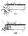
- the figure 3 illustrates the assembly assembly 2 in a partially assembled configuration, wherein the rail 6 is fixed on the attachment face 14, while the stop 8 is not yet fixed on the body member 4.
- the figure 4 illustrates assembly assembly 2 after assembly.
- the stop 8 is inserted between the free end 9 and the bearing face 18 by a combined movement of rotation and depression (arrows M on the figure 3 ) for inserting the post 40 ( figure 1 ) in the end portion 32, and placing the insert 46 opposite the orifice 50 to allow the insertion of the screw 52 through the insert 46 and the orifice 50.
- the abutment body 35 and the protuberances 44 are dimensioned so that the abutment 8 inserted between the free end 9 and the bearing face 18 is in abutment by its front face 36 against the free end 9, and supported by its protuberances 44 against the bearing face 18.
- the protuberances 44 are dimensioned so that the stop 8 is held compressed between the end 9 and the bearing face 18, which ensures a precise contact and positioning of the abutment 8 by wedging it against the free end 9 in the longitudinal direction L of the end portion 32.
- the stop 8 is held in place by the screw 52 in a direction of attachment F ( Figure 4 ) perpendicular to the direction L and to the fixing face 14.
- the direction F is parallel to the end face 34.
- the inclination of the bearing face 18 facilitates the engagement of the abutment 8 between the bearing face 18 and the free end 9, allows the biasing of the stop 8 in the direction F maintains the abutment 8 requested in direction of the free end 9 in the longitudinal direction L.
- the positioning of the stop 8 is done automatically when tightening the screw 52. It does not depend on an operator, which limits the risk of mispositioning the stop.
- the insert 46 takes up the tightening forces of the screw 52 to avoid crushing the abutment body 35 in the direction F.
- the abutment 8 can be obtained easily from a mold initially intended for the production of abutments without protuberances. Thus, the invention can be implemented at low cost.
Landscapes
- Power-Operated Mechanisms For Wings (AREA)
- Lock And Its Accessories (AREA)
- Window Of Vehicle (AREA)
Claims (10)
- Montageanordnung für eine Schiebetür eines Kraftfahrzeugs, des Typs, der einen Träger (4) und eine lang gestreckte Schiene (6), die dazu bestimmt ist, einen Schlitten der Schiebetür gleitend aufzunehmen, aufweist, wobei die Schiene (6) einen Endabschnitt, der sich in einer Längsrichtung (L) erstreckt und an einer Befestigungsfläche (14) des Trägers (4) befestigt ist, und einen Anschlag (8), der am freien Ende (9) des Endabschnitts der Schiene (6) angeordnet ist, um die Verlagerung des Schlittens (6) längs der Schiene zu begrenzen, aufweist,
dadurch gekennzeichnet, dass der Anschlag (8) im Wesentlichen in der Längsrichtung (L) zwischen dem Ende (9) und einer Abstützfläche (18) des Trägers (4), die sich in der Längsrichtung (L) gegenüber dem freien Ende (9) befindet, durch Druck vorbelastet ist. - Anordnung nach Anspruch 1, wobei die Abstützfläche (18) in Bezug auf eine Ebene senkrecht zu der Längsrichtung (L) geneigt ist.
- Anordnung nach Anspruch 2, wobei der Anschlag (8) anliegend an die Abstützfläche (18) längs einer Befestigungsrichtung (F), die in Bezug auf die Abstützfläche (18) geneigt ist, gehalten wird.
- Anordnung nach Anspruch 3, wobei die Befestigungsrichtung (F) zu der Längsrichtung (L) im Wesentlichen senkrecht ist.
- Anordnung nach Anspruch 3 oder 4, wobei die Befestigungsrichtung (F) zu der Befestigungsfläche (14) des Trägers (4) im Wesentlichen senkrecht ist.
- Anordnung nach einem der vorhergehenden Ansprüche, wobei sich die Abstützfläche (18) dem freien Ende (9) der Schiene (6) in Richtung der Befestigungsfläche (14) annähert.
- Anordnung nach einem der vorhergehenden Ansprüche, wobei der Anschlag (8) am Träger (4) befestigt ist.
- Anordnung nach einem der vorhergehenden Ansprüche, wobei der Anschlag (8) einen Anschlagkörper (35) und wenigstens einen vom Anschlagkörper (35) vorstehenden elastischen Vorsprung (44), der dazu vorgesehen ist, an der Abstützfläche (18) in Anschlag zu gelangen, aufweist.
- Kraftfahrzeug, das eine Anordnung nach einem der vorhergehenden Ansprüche enthält, wobei der Träger ein Karosserieelement (4) des Kraftfahrzeugs ist.
- Verfahren zur Montage einer Anordnung nach einem der vorhergehenden Ansprüche, das die folgenden Schritte enthält:- Befestigen der Schiene (6) an dem Träger (4),- Einsetzen des Anschlags (8) zwischen die Abstützfläche (14) und das Ende der Schiene (6),- Befestigen des Anschlags (8) mit Hilfe wenigstens eines Befestigungsorgans (52), das vorgesehen ist, um auf den Anschlag (8) eine Vorbelastungskraft auszuüben, derart, dass sich der Anschlag (8) an der Abstützfläche (18) und der Stirnfläche (34) der Schiene (6) abstützt.
Applications Claiming Priority (1)
| Application Number | Priority Date | Filing Date | Title |
|---|---|---|---|
| FR0758991A FR2923518B1 (fr) | 2007-11-13 | 2007-11-13 | Ensemble de montage d'une porte coulissante de vehicule automobile. |
Publications (2)
| Publication Number | Publication Date |
|---|---|
| EP2060718A1 EP2060718A1 (de) | 2009-05-20 |
| EP2060718B1 true EP2060718B1 (de) | 2010-01-20 |
Family
ID=39473602
Family Applications (1)
| Application Number | Title | Priority Date | Filing Date |
|---|---|---|---|
| EP08168329A Active EP2060718B1 (de) | 2007-11-13 | 2008-11-05 | Montagekit für eine Schiebetür eines Kraftfahrzeugs |
Country Status (6)
| Country | Link |
|---|---|
| EP (1) | EP2060718B1 (de) |
| AT (1) | ATE455921T1 (de) |
| DE (1) | DE602008000582D1 (de) |
| ES (1) | ES2338388T3 (de) |
| FR (1) | FR2923518B1 (de) |
| PT (1) | PT2060718E (de) |
Families Citing this family (1)
| Publication number | Priority date | Publication date | Assignee | Title |
|---|---|---|---|---|
| FR3047445B1 (fr) * | 2016-02-09 | 2018-02-23 | Peugeot Citroen Automobiles Sa | Fermeture d’un boitier de rail central de porte laterale coulissante de vehicule automobile |
Family Cites Families (3)
| Publication number | Priority date | Publication date | Assignee | Title |
|---|---|---|---|---|
| US5791723A (en) * | 1997-01-16 | 1998-08-11 | Ford Motor Company | Bumper wedge for automotive vehicle sliding door |
| FR2817276B1 (fr) * | 2000-11-24 | 2003-08-08 | Renault | Centreur de porte coulissante, notamment pour automobile |
| GB2410990B (en) * | 2004-02-10 | 2007-11-21 | Ford Global Tech Llc | An adjustable bumpstop |
-
2007
- 2007-11-13 FR FR0758991A patent/FR2923518B1/fr not_active Expired - Fee Related
-
2008
- 2008-11-05 DE DE602008000582T patent/DE602008000582D1/de active Active
- 2008-11-05 PT PT08168329T patent/PT2060718E/pt unknown
- 2008-11-05 AT AT08168329T patent/ATE455921T1/de not_active IP Right Cessation
- 2008-11-05 EP EP08168329A patent/EP2060718B1/de active Active
- 2008-11-05 ES ES08168329T patent/ES2338388T3/es active Active
Also Published As
| Publication number | Publication date |
|---|---|
| FR2923518A1 (fr) | 2009-05-15 |
| ES2338388T3 (es) | 2010-05-06 |
| DE602008000582D1 (de) | 2010-03-11 |
| ATE455921T1 (de) | 2010-02-15 |
| PT2060718E (pt) | 2010-03-19 |
| FR2923518B1 (fr) | 2009-12-11 |
| EP2060718A1 (de) | 2009-05-20 |
Similar Documents
| Publication | Publication Date | Title |
|---|---|---|
| EP3927601B1 (de) | Befestigungseinrichtung eines schutzkomponentes unter motor | |
| EP2060718B1 (de) | Montagekit für eine Schiebetür eines Kraftfahrzeugs | |
| EP3996954B1 (de) | Vorrichtung zur befestigung eines seitlichen randprofilteils einer kraftfahrzeugtür | |
| EP2062804A1 (de) | Vorrichtung und Verfahren zur Befestigung einer Kotflügeleinheit an der Wagenkastenwand eines Kraftfahrzeugs | |
| FR3007330A1 (fr) | Dispositif de cales pour le maintien en position selon l'axe z, d'un element a monter tel qu'un vitrage dans un encadrement d'un element de carrosserie | |
| EP1052357B1 (de) | Schliessblech | |
| EP4101721A1 (de) | Kit zur montage einer verkleidungsplatte an einer karosserie eines transportfahrzeugs, karosserie und fahrzeug mit einem solchen kit und entsprechendes montageverfahren | |
| EP2085623B1 (de) | Verfahren zur Montage eines Spoilers an ein Kraftfahrzeug und entsprechende Montageanordnung | |
| FR3101811A1 (fr) | Profilé d’étanchéité destiné à être monté sur un bord supérieur d’un panneau extérieur de porte de véhicule automobile et pourvue d’une vitre | |
| EP4164905B1 (de) | Kraftfahrzeugtürverkleidung | |
| FR3050412B1 (fr) | Systeme de recouvrement d’un compartiment a bagages de vehicule automobile | |
| EP4534781A1 (de) | Verriegelungsbeschlag-steuervorrichtung für tür- oder fensterrahmen | |
| EP4105096A1 (de) | Verkleidungsanordnung für eine fahrzeugkarosserie, insbesondere für ein schienenfahrzeug | |
| EP2928711B1 (de) | Fahrzeugseitentür mit einer vorrichtung zur festlegung der führungsschiene eines öffnungsfähigen fensters | |
| FR3101812A1 (fr) | Profilé d’étanchéité d’un panneau extérieur de porte de véhicule automobile | |
| FR2738322A1 (fr) | Dispositif pour renforcer l'etancheite d'un joint | |
| WO2024236235A1 (fr) | Support de vitre pour ouvrant latéral d'un véhicule | |
| FR3117989A1 (fr) | Enjoliveur extérieur pour ouvrant. | |
| FR2877882A1 (fr) | Porte vitree comportant un guide de vitre muni d'un element s'opposant au vrillage | |
| EP1568835A1 (de) | Begrenzungsanschlag für die Querverschiebung einer Schiebeglasscheibe einer Kraftfahrzeugtür | |
| FR2935013A1 (fr) | Oeillet de fixation d'une vitre, leve-vitre, element de carrosserie et assemblage d'un oeillet avec un curseur | |
| FR2664718A1 (fr) | Perfectionnement aux manivelles pour la manóoeuvre manuelle de la glace d'un vehicule. | |
| FR2784949A1 (fr) | Siege de vehicule automobile comportant un accoudoir rabattable | |
| FR2937946A1 (fr) | Piece de recouvrement d'un element de carrosserie d'un vehicule automobile | |
| FR2957111A1 (fr) | Ensemble de fixation d'une butee de porte coulissante a un rail de guidage, et systeme de translation d'une porte coulissante comprenant un tel ensemble |
Legal Events
| Date | Code | Title | Description |
|---|---|---|---|
| PUAI | Public reference made under article 153(3) epc to a published international application that has entered the european phase |
Free format text: ORIGINAL CODE: 0009012 |
|
| AK | Designated contracting states |
Kind code of ref document: A1 Designated state(s): AT BE BG CH CY CZ DE DK EE ES FI FR GB GR HR HU IE IS IT LI LT LU LV MC MT NL NO PL PT RO SE SI SK TR |
|
| AX | Request for extension of the european patent |
Extension state: AL BA MK RS |
|
| 17P | Request for examination filed |
Effective date: 20090923 |
|
| GRAP | Despatch of communication of intention to grant a patent |
Free format text: ORIGINAL CODE: EPIDOSNIGR1 |
|
| GRAS | Grant fee paid |
Free format text: ORIGINAL CODE: EPIDOSNIGR3 |
|
| GRAA | (expected) grant |
Free format text: ORIGINAL CODE: 0009210 |
|
| AK | Designated contracting states |
Kind code of ref document: B1 Designated state(s): AT BE BG CH CY CZ DE DK EE ES FI FR GB GR HR HU IE IS IT LI LT LU LV MC MT NL NO PL PT RO SE SI SK TR |
|
| REG | Reference to a national code |
Ref country code: GB Ref legal event code: FG4D Free format text: NOT ENGLISH |
|
| AKX | Designation fees paid |
Designated state(s): AT BE BG CH CY CZ DE DK EE ES FI FR GB GR HR HU IE IS IT LI LT LU LV MC MT NL NO PL PT RO SE SI SK TR |
|
| REG | Reference to a national code |
Ref country code: CH Ref legal event code: EP |
|
| REG | Reference to a national code |
Ref country code: IE Ref legal event code: FG4D |
|
| REF | Corresponds to: |
Ref document number: 602008000582 Country of ref document: DE Date of ref document: 20100311 Kind code of ref document: P |
|
| REG | Reference to a national code |
Ref country code: PT Ref legal event code: SC4A Free format text: AVAILABILITY OF NATIONAL TRANSLATION Effective date: 20100309 |
|
| REG | Reference to a national code |
Ref country code: ES Ref legal event code: FG2A Ref document number: 2338388 Country of ref document: ES Kind code of ref document: T3 |
|
| REG | Reference to a national code |
Ref country code: NL Ref legal event code: VDEP Effective date: 20100120 |
|
| LTIE | Lt: invalidation of european patent or patent extension |
Effective date: 20100120 |
|
| PG25 | Lapsed in a contracting state [announced via postgrant information from national office to epo] |
Ref country code: AT Free format text: LAPSE BECAUSE OF FAILURE TO SUBMIT A TRANSLATION OF THE DESCRIPTION OR TO PAY THE FEE WITHIN THE PRESCRIBED TIME-LIMIT Effective date: 20100120 |
|
| REG | Reference to a national code |
Ref country code: GB Ref legal event code: 746 Effective date: 20100607 |
|
| REG | Reference to a national code |
Ref country code: SK Ref legal event code: T3 Ref document number: E 6962 Country of ref document: SK |
|
| PG25 | Lapsed in a contracting state [announced via postgrant information from national office to epo] |
Ref country code: NL Free format text: LAPSE BECAUSE OF FAILURE TO SUBMIT A TRANSLATION OF THE DESCRIPTION OR TO PAY THE FEE WITHIN THE PRESCRIBED TIME-LIMIT Effective date: 20100120 Ref country code: LT Free format text: LAPSE BECAUSE OF FAILURE TO SUBMIT A TRANSLATION OF THE DESCRIPTION OR TO PAY THE FEE WITHIN THE PRESCRIBED TIME-LIMIT Effective date: 20100120 Ref country code: HR Free format text: LAPSE BECAUSE OF FAILURE TO SUBMIT A TRANSLATION OF THE DESCRIPTION OR TO PAY THE FEE WITHIN THE PRESCRIBED TIME-LIMIT Effective date: 20100120 Ref country code: NO Free format text: LAPSE BECAUSE OF FAILURE TO SUBMIT A TRANSLATION OF THE DESCRIPTION OR TO PAY THE FEE WITHIN THE PRESCRIBED TIME-LIMIT Effective date: 20100420 Ref country code: IS Free format text: LAPSE BECAUSE OF FAILURE TO SUBMIT A TRANSLATION OF THE DESCRIPTION OR TO PAY THE FEE WITHIN THE PRESCRIBED TIME-LIMIT Effective date: 20100520 |
|
| REG | Reference to a national code |
Ref country code: IE Ref legal event code: FD4D |
|
| PG25 | Lapsed in a contracting state [announced via postgrant information from national office to epo] |
Ref country code: PL Free format text: LAPSE BECAUSE OF FAILURE TO SUBMIT A TRANSLATION OF THE DESCRIPTION OR TO PAY THE FEE WITHIN THE PRESCRIBED TIME-LIMIT Effective date: 20100120 Ref country code: FI Free format text: LAPSE BECAUSE OF FAILURE TO SUBMIT A TRANSLATION OF THE DESCRIPTION OR TO PAY THE FEE WITHIN THE PRESCRIBED TIME-LIMIT Effective date: 20100120 Ref country code: SI Free format text: LAPSE BECAUSE OF FAILURE TO SUBMIT A TRANSLATION OF THE DESCRIPTION OR TO PAY THE FEE WITHIN THE PRESCRIBED TIME-LIMIT Effective date: 20100120 Ref country code: LV Free format text: LAPSE BECAUSE OF FAILURE TO SUBMIT A TRANSLATION OF THE DESCRIPTION OR TO PAY THE FEE WITHIN THE PRESCRIBED TIME-LIMIT Effective date: 20100120 |
|
| PG25 | Lapsed in a contracting state [announced via postgrant information from national office to epo] |
Ref country code: SE Free format text: LAPSE BECAUSE OF FAILURE TO SUBMIT A TRANSLATION OF THE DESCRIPTION OR TO PAY THE FEE WITHIN THE PRESCRIBED TIME-LIMIT Effective date: 20100120 Ref country code: CY Free format text: LAPSE BECAUSE OF FAILURE TO SUBMIT A TRANSLATION OF THE DESCRIPTION OR TO PAY THE FEE WITHIN THE PRESCRIBED TIME-LIMIT Effective date: 20100120 Ref country code: RO Free format text: LAPSE BECAUSE OF FAILURE TO SUBMIT A TRANSLATION OF THE DESCRIPTION OR TO PAY THE FEE WITHIN THE PRESCRIBED TIME-LIMIT Effective date: 20100120 Ref country code: EE Free format text: LAPSE BECAUSE OF FAILURE TO SUBMIT A TRANSLATION OF THE DESCRIPTION OR TO PAY THE FEE WITHIN THE PRESCRIBED TIME-LIMIT Effective date: 20100120 Ref country code: GR Free format text: LAPSE BECAUSE OF FAILURE TO SUBMIT A TRANSLATION OF THE DESCRIPTION OR TO PAY THE FEE WITHIN THE PRESCRIBED TIME-LIMIT Effective date: 20100421 Ref country code: IE Free format text: LAPSE BECAUSE OF FAILURE TO SUBMIT A TRANSLATION OF THE DESCRIPTION OR TO PAY THE FEE WITHIN THE PRESCRIBED TIME-LIMIT Effective date: 20100120 |
|
| PLBE | No opposition filed within time limit |
Free format text: ORIGINAL CODE: 0009261 |
|
| STAA | Information on the status of an ep patent application or granted ep patent |
Free format text: STATUS: NO OPPOSITION FILED WITHIN TIME LIMIT |
|
| PG25 | Lapsed in a contracting state [announced via postgrant information from national office to epo] |
Ref country code: CZ Free format text: LAPSE BECAUSE OF FAILURE TO SUBMIT A TRANSLATION OF THE DESCRIPTION OR TO PAY THE FEE WITHIN THE PRESCRIBED TIME-LIMIT Effective date: 20100120 Ref country code: BG Free format text: LAPSE BECAUSE OF FAILURE TO SUBMIT A TRANSLATION OF THE DESCRIPTION OR TO PAY THE FEE WITHIN THE PRESCRIBED TIME-LIMIT Effective date: 20100420 |
|
| 26N | No opposition filed |
Effective date: 20101021 |
|
| PG25 | Lapsed in a contracting state [announced via postgrant information from national office to epo] |
Ref country code: DK Free format text: LAPSE BECAUSE OF FAILURE TO SUBMIT A TRANSLATION OF THE DESCRIPTION OR TO PAY THE FEE WITHIN THE PRESCRIBED TIME-LIMIT Effective date: 20100120 |
|
| REG | Reference to a national code |
Ref country code: ES Ref legal event code: GC2A Effective date: 20110217 |
|
| BERE | Be: lapsed |
Owner name: PEUGEOT CITROEN AUTOMOBILES SA Effective date: 20101130 |
|
| PG25 | Lapsed in a contracting state [announced via postgrant information from national office to epo] |
Ref country code: MC Free format text: LAPSE BECAUSE OF NON-PAYMENT OF DUE FEES Effective date: 20101130 |
|
| PG25 | Lapsed in a contracting state [announced via postgrant information from national office to epo] |
Ref country code: BE Free format text: LAPSE BECAUSE OF NON-PAYMENT OF DUE FEES Effective date: 20101130 |
|
| PG25 | Lapsed in a contracting state [announced via postgrant information from national office to epo] |
Ref country code: MT Free format text: LAPSE BECAUSE OF FAILURE TO SUBMIT A TRANSLATION OF THE DESCRIPTION OR TO PAY THE FEE WITHIN THE PRESCRIBED TIME-LIMIT Effective date: 20100120 |
|
| PG25 | Lapsed in a contracting state [announced via postgrant information from national office to epo] |
Ref country code: HU Free format text: LAPSE BECAUSE OF FAILURE TO SUBMIT A TRANSLATION OF THE DESCRIPTION OR TO PAY THE FEE WITHIN THE PRESCRIBED TIME-LIMIT Effective date: 20100721 Ref country code: LU Free format text: LAPSE BECAUSE OF NON-PAYMENT OF DUE FEES Effective date: 20101105 |
|
| PG25 | Lapsed in a contracting state [announced via postgrant information from national office to epo] |
Ref country code: TR Free format text: LAPSE BECAUSE OF FAILURE TO SUBMIT A TRANSLATION OF THE DESCRIPTION OR TO PAY THE FEE WITHIN THE PRESCRIBED TIME-LIMIT Effective date: 20100120 |
|
| REG | Reference to a national code |
Ref country code: CH Ref legal event code: PL |
|
| PG25 | Lapsed in a contracting state [announced via postgrant information from national office to epo] |
Ref country code: LI Free format text: LAPSE BECAUSE OF NON-PAYMENT OF DUE FEES Effective date: 20121130 Ref country code: CH Free format text: LAPSE BECAUSE OF NON-PAYMENT OF DUE FEES Effective date: 20121130 |
|
| REG | Reference to a national code |
Ref country code: FR Ref legal event code: PLFP Year of fee payment: 8 |
|
| REG | Reference to a national code |
Ref country code: FR Ref legal event code: PLFP Year of fee payment: 9 |
|
| PGFP | Annual fee paid to national office [announced via postgrant information from national office to epo] |
Ref country code: GB Payment date: 20161027 Year of fee payment: 9 |
|
| REG | Reference to a national code |
Ref country code: FR Ref legal event code: PLFP Year of fee payment: 10 |
|
| PGFP | Annual fee paid to national office [announced via postgrant information from national office to epo] |
Ref country code: IT Payment date: 20171020 Year of fee payment: 10 |
|
| REG | Reference to a national code |
Ref country code: FR Ref legal event code: CA Effective date: 20180312 Ref country code: FR Ref legal event code: CD Owner name: PEUGEOT CITROEN AUTOMOBILES SA, FR Effective date: 20180312 |
|
| GBPC | Gb: european patent ceased through non-payment of renewal fee |
Effective date: 20171105 |
|
| REG | Reference to a national code |
Ref country code: FR Ref legal event code: PLFP Year of fee payment: 11 |
|
| PG25 | Lapsed in a contracting state [announced via postgrant information from national office to epo] |
Ref country code: GB Free format text: LAPSE BECAUSE OF NON-PAYMENT OF DUE FEES Effective date: 20171105 |
|
| PG25 | Lapsed in a contracting state [announced via postgrant information from national office to epo] |
Ref country code: IT Free format text: LAPSE BECAUSE OF NON-PAYMENT OF DUE FEES Effective date: 20181105 |
|
| PGFP | Annual fee paid to national office [announced via postgrant information from national office to epo] |
Ref country code: PT Payment date: 20241022 Year of fee payment: 17 |
|
| PGFP | Annual fee paid to national office [announced via postgrant information from national office to epo] |
Ref country code: DE Payment date: 20241022 Year of fee payment: 17 |
|
| PGFP | Annual fee paid to national office [announced via postgrant information from national office to epo] |
Ref country code: ES Payment date: 20241202 Year of fee payment: 17 |
|
| PGFP | Annual fee paid to national office [announced via postgrant information from national office to epo] |
Ref country code: FR Payment date: 20251023 Year of fee payment: 18 |
|
| PGFP | Annual fee paid to national office [announced via postgrant information from national office to epo] |
Ref country code: SK Payment date: 20251029 Year of fee payment: 18 |