EP2058587B1 - Bath light with indirect share of light - Google Patents
Bath light with indirect share of light Download PDFInfo
- Publication number
- EP2058587B1 EP2058587B1 EP08019624A EP08019624A EP2058587B1 EP 2058587 B1 EP2058587 B1 EP 2058587B1 EP 08019624 A EP08019624 A EP 08019624A EP 08019624 A EP08019624 A EP 08019624A EP 2058587 B1 EP2058587 B1 EP 2058587B1
- Authority
- EP
- European Patent Office
- Prior art keywords
- housing
- housing base
- light
- lighting fixture
- translucent
- Prior art date
- Legal status (The legal status is an assumption and is not a legal conclusion. Google has not performed a legal analysis and makes no representation as to the accuracy of the status listed.)
- Not-in-force
Links
Images


Classifications
-
- F—MECHANICAL ENGINEERING; LIGHTING; HEATING; WEAPONS; BLASTING
- F21—LIGHTING
- F21V—FUNCTIONAL FEATURES OR DETAILS OF LIGHTING DEVICES OR SYSTEMS THEREOF; STRUCTURAL COMBINATIONS OF LIGHTING DEVICES WITH OTHER ARTICLES, NOT OTHERWISE PROVIDED FOR
- F21V7/00—Reflectors for light sources
- F21V7/0008—Reflectors for light sources providing for indirect lighting
- F21V7/0016—Reflectors for light sources providing for indirect lighting on lighting devices that also provide for direct lighting, e.g. by means of independent light sources, by splitting of the light beam, by switching between both lighting modes
-
- F—MECHANICAL ENGINEERING; LIGHTING; HEATING; WEAPONS; BLASTING
- F21—LIGHTING
- F21S—NON-PORTABLE LIGHTING DEVICES; SYSTEMS THEREOF; VEHICLE LIGHTING DEVICES SPECIALLY ADAPTED FOR VEHICLE EXTERIORS
- F21S8/00—Lighting devices intended for fixed installation
- F21S8/04—Lighting devices intended for fixed installation intended only for mounting on a ceiling or the like overhead structures
-
- F—MECHANICAL ENGINEERING; LIGHTING; HEATING; WEAPONS; BLASTING
- F21—LIGHTING
- F21V—FUNCTIONAL FEATURES OR DETAILS OF LIGHTING DEVICES OR SYSTEMS THEREOF; STRUCTURAL COMBINATIONS OF LIGHTING DEVICES WITH OTHER ARTICLES, NOT OTHERWISE PROVIDED FOR
- F21V13/00—Producing particular characteristics or distribution of the light emitted by means of a combination of elements specified in two or more of main groups F21V1/00 - F21V11/00
- F21V13/02—Combinations of only two kinds of elements
- F21V13/04—Combinations of only two kinds of elements the elements being reflectors and refractors
-
- F—MECHANICAL ENGINEERING; LIGHTING; HEATING; WEAPONS; BLASTING
- F21—LIGHTING
- F21V—FUNCTIONAL FEATURES OR DETAILS OF LIGHTING DEVICES OR SYSTEMS THEREOF; STRUCTURAL COMBINATIONS OF LIGHTING DEVICES WITH OTHER ARTICLES, NOT OTHERWISE PROVIDED FOR
- F21V5/00—Refractors for light sources
- F21V5/02—Refractors for light sources of prismatic shape
-
- F—MECHANICAL ENGINEERING; LIGHTING; HEATING; WEAPONS; BLASTING
- F21—LIGHTING
- F21Y—INDEXING SCHEME ASSOCIATED WITH SUBCLASSES F21K, F21L, F21S and F21V, RELATING TO THE FORM OR THE KIND OF THE LIGHT SOURCES OR OF THE COLOUR OF THE LIGHT EMITTED
- F21Y2103/00—Elongate light sources, e.g. fluorescent tubes
-
- F—MECHANICAL ENGINEERING; LIGHTING; HEATING; WEAPONS; BLASTING
- F21—LIGHTING
- F21Y—INDEXING SCHEME ASSOCIATED WITH SUBCLASSES F21K, F21L, F21S and F21V, RELATING TO THE FORM OR THE KIND OF THE LIGHT SOURCES OR OF THE COLOUR OF THE LIGHT EMITTED
- F21Y2113/00—Combination of light sources
Definitions
- the present invention relates to trough lamps, in particular trough lamps, which allow for the production of indirect lighting a light exit in the direction of the mounting side of the lamp to lighten the ceiling or wall on which the lamp is mounted.
- a lamp of the type mentioned is, for example, in the FIG. 1 shown.
- the lamp comprises a housing base part 2 and a transparent housing cover 5.
- the light of the lamp 1 can pass not only through the transparent cover 5, but also through the housing base part 2.
- the illustrated light beam 8 is used to produce an indirect illumination in the direction of the ceiling or wall to which the lamp is attached.
- a wet room lamp with a two-part closed housing the housing base part consists of a translucent material, is made of EP 0 726 420 A1 known.
- EP 1 847 766 A1 is known an interior light, which has room and ceiling side light exit surfaces.
- the luminaire comprises a carrier hollow profile, which has two fluorescent lamps laterally, which are surrounded by closed light guiding chambers. Above the fluorescent lamps, a transparent cover is provided which has a structuring on the side facing the lamps. For deflecting the light emerging from the transparent covers, separate light distribution wings (8) are provided on the carrier profile, which are adjustable in particular in the inclination relative to the vertical center plane of the carrier hollow profile.
- the lamp is preferably suspended from the end parts.
- Out DE 79 10 659 U1 is a pendant lamp with a partially upwardly radiating optics known.
- the pendant lamp has a downwardly reflecting mirror optics, which has a longitudinal slot in its upper third, so that part of the radiation of a light source can escape upwards.
- lenses are arranged, for example in the form of a prismatic disc.
- the object is achieved by a luminaire according to claim 1.
- the invention provides a luminaire with a housing which comprises a GeHousebasisteil and a translucent housing cover, which enclose an interior of the housing, wherein at least one lamp is disposed in the interior of the housing and the Housing base part on the side facing away from the light source has a mounting side for fixing the lamp, wherein the housing base part has at least a portion which is formed of a translucent material, passes through the light of the bulb for generating an indirect illumination.
- light-refracting structures are arranged on the translucent subregion of the housing base part, which deflect the light passing through the subarea in a direction away from the mounting side.
- the invention is based on the observation that the illumination of a room can be improved by the indirect portion of the light radiation which the luminaire generates, if the indirect part is further distributed in the depth of the room.
- the luminaire according to the invention provides light-guiding structures in the light passage region of the housing base part, which deflect the light in such a way that the ceiling or wall on which the luminaire is mounted is illuminated over a larger area.
- the refractive structures have a constant cross-section in a cross-section perpendicular to a longitudinal extension of the luminous means over at least part of the longitudinal extent.
- This embodiment is particularly advantageous for linear luminaires, which have an elongated luminous means, such as one or more fluorescent tubes. Due to the constant cross-section of the refractive structures, the indirect component of the light is redirected in the desired direction over the entire length of the luminaire.
- the thickness of the refractive structures decreases in each case in the cross section perpendicular to the longitudinal extent of the luminous means, from the side remote from the mounting side to the side facing the mounting side.
- the light-directing structures which are formed for example of a transparent plastic, such as PMMA or PU, or of glass, the desired deflection can be generated in the direction away from the mounting side.
- the refractive structures are formed by prism elements.
- the prism elements may extend, for example, parallel to the longitudinal extent of the luminous means on the translucent subregion of the housing base part.
- other refractive structures such as cones or truncated cones, pyramids or truncated pyramids, grooves or lenses may be provided on the housing base part for deflecting the light.
- prism elements which have two asymmetrical legs.
- the base side of the prism element is planar to the surface which is defined by the translucent part of the housing base part.
- the asymmetrical legs form a protrusion of the translucent portion of the housing base part.
- the shorter leg can be arranged on the side facing away from the mounting side of the prism and the longer of the two legs can be arranged on the side facing the mounting side of the prism.
- a plurality, in particular of identical cross-section may be provided, which extend parallel to one another in the translucent subregion of the housing base part.
- the refractive structures are preferably arranged on the side of the housing base part facing the interior.
- the housing base part may be smooth on the outside, so that the housing is easier to clean from the outside, because there are no uneven structures on the outside.
- the housing base part has at least two translucent sections with refractive structures which extend on both sides of the mounting side of the housing base section.
- refractive structures may be arranged mirror-symmetrically with respect to a sectional plane which runs perpendicular to the mounting side of the luminaire in the longitudinal direction of the luminaire. In the case of a ceiling light, this corresponds to the vertical plane.
- the housing base part is substantially completely formed of a light-transmitting material.
- the housing base may be formed entirely of glass or a plastic material, except for electrical components or internals disposed on the inside of the housing base.
- Such a housing can be produced inexpensively and also has the advantage on that the housing has a uniform coefficient of expansion, so that when heating the housing by the operation of the lamps no stresses in the material occur.
- the refractive structures may be formed integrally with the housing base part or at least with the translucent portion of the housing base part.
- a reflector is arranged in the interior of the housing between the housing base part and the lighting means.
- the reflector primarily provides a light direction in the direction of the main emission of the lamp for direct illumination through the transparent housing cover.
- the reflector is set up so that light passes from the luminous means on a straight path past the reflector and through an opening in the reflector to the translucent portion of the housing base part. This proportion of light provides the desired indirect lighting.
- the reflector may include one or more reflective surfaces arranged to reflect light from the bulb to the translucent portion of the barrel base.
- the indirect component of the light radiation can be formed either directly by the illuminant and / or by reflection at the reflector.
- the indirect radiation passes through the translucent portion of the housing base portion on which the refractive structures are arranged to achieve the desired light distribution.
- the light radiation which impinges on the reflector on the translucent portion of the housing base part hits in a shallower angle relative to the mounting side of the housing base part on the translucent portion than that light radiation which impinges on the same location of the translucent portion without reflection on the reflector.
- the angles are determined in a cross-sectional area perpendicular to the longitudinal extent of the lamp.
- the housing of the lamp is completely closed.
- it may be a wet room light, which is sealed against penetrating moisture, jet water or spray water.
- An embodiment of the luminaire can realize, for example, the degree of protection IP 65 according to EN60598-1 in the version from the year 2004.
- the translucent portions of the housing base portion or the complete housing base portion are provided with a color filter, e.g. by coloring the material of the housing base part or by applying a correspondingly colored coating.
- a colored indirect portion of the light is generated.
- the colored deposition of the indirect component not only provides an appealing aesthetic impression, but this component can also fulfill the technical function, such as, e.g. a signal effect.
- the color of the indirect light component can be adapted to the spectral reflection properties of the wall or ceiling color to provide a particularly efficient indirect lighting of the room.
- a trough-shaped housing base part 2 defines a downwardly open shape in cross section. In the upper area, the housing base part is approximately U-shaped. In this area, electrical components (not shown) may be arranged.
- the housing base part 2 is closed by a transparent housing cover 5 down.
- the transparent housing cover 5 is likewise trough-shaped and terminates with the housing base part 2 a completely closed interior.
- a seal 6 may be provided, which ensures a dust-tight or moisture-tight closure between the housing base part 2 and the transparent housing cover 5.
- the housing base part 2 and the housing cover 5 may, for example, be connected to one another with clips on the outside. Alternatively, a latching connection may also be provided or, in addition, a hinge may be provided on at least one longitudinal side (not shown in the figures).
- a light source 1 is arranged in the interior defined by the housing base part 2 and the transparent housing cover 5, a light source 1 is arranged.
- the light source 1 is in the FIG. 1 shown in cross section. It is a tubular fluorescent lamp, which is socketed in the interior of the lamp at the longitudinal ends.
- the light emanating from the light source 1 predominantly passes through the transparent housing cover 5.
- the transparent housing cover 5 has a corrugation on the inside, which ensures a scattering of light passing through the housing cover.
- the proportion of the light radiation which passes through the transparent housing cover 5 forms a large part of the luminous flux of the luminaire, which is intended for direct illumination.
- a part of the luminous flux which is shown in the figures as a light beam 8 also passes through the housing base part.
- the housing base part is completely formed in the embodiment shown from a transparent plastic, so that the passage of light is made possible.
- refractive structures 10 arranged in the area next to the U-shaped portion of the housing base part and the connecting edge to the housing cover 5 in the area next to the U-shaped portion of the housing base part and the connecting edge to the housing cover 5 are on the inside of the housing base part 2 refractive structures 10 arranged.
- the mode of action of the refractive structures 10 will be described with reference to FIGS FIGS. 6 to 8 , which illustrate the corresponding section of the housing base part 2, explained. Without the refractive structures, as in the FIG. 6 shown, the light passes through the housing cover substantially in a straight line.
- the luminaire according to the invention has light-refracting structures 10 on the inside.
- These are prism elements which extend in the longitudinal direction of the luminaire parallel to the luminous means on the inside of the housing base part 2.
- the prism elements have two to the interior of the luminaire facing legs 11 and 12.
- the leg 11 points in the direction of the mounting side 3 of the lamp, while the leg 12 is arranged on the side facing away from the mounting side of the prism 10.
- a light beam which is approximately perpendicular to the housing base part, from the original direction (shown in phantom in the figure) is broken.
- the leg 12 is formed slightly shorter than the leg 11. Furthermore, the leg 12 extends approximately parallel to a radial line, which emanates from the lamp and impinges on the housing cover. As a result, less light passes through the leg 12 as compared to the leg 11. In general, the thickness of the prismatic element decreases from the side facing away from the luminaire mounting side 3, ie from the leg 12, to the side facing the luminaire mounting side 3, ie along the leg 11. This shape and the arrangement relative to the light source, the desired deflection effect is achieved.
- FIG. 8 shows an alternative embodiment of the refractive structure 10.
- the leg 11 ' is approximately equal to the leg 12'.
- the same deflection effect as previously described, achieved.
- FIG. 5 The total light distribution which is produced by an embodiment of the luminaire according to the invention is in FIG. 5 shown in a polar diagram.
- FIG. 4 a polar diagram of the luminous intensity distribution of a luminaire without refractive structures 10.
- the light distribution shows two pronounced maxima 13 in the direction of the main emission of the luminaire, which form the direct component of the light intensity. This light is essentially generated by the proportion of the light passing through the transparent housing cover 5.
- the light distribution of the indirect component 14 can be seen on the opposite side of the main maxima 13, ie on the side facing the mounting side of the lamp.
- FIGS. 4 and 5 shows that the indirect portion 14 of a lamp according to the present invention (see. FIG. 5 ) wider and flatter than in a lamp according to the prior art (see. FIG. 4 ).
- This effect is caused by the refractive structure 10 on the housing base side 2 and allows a large-scale and uniform illumination of the ceiling to which the lamp is mounted.
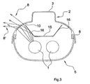
- FIG. 3 shows a cross section through an alternative embodiment of the lamp according to the invention. This is a two-lamp lamp. The corresponding components are denoted by the same reference numerals as in FIG FIG. 2 designated.
- a reflector 15 is arranged between the one or more lamps 1 of the lamp and the housing base part 5. A significant proportion of the light radiation from the light source (s) is directed by the reflector 15 in the direction of the transparent housing cover 5.
- laterally angled portions 16 are provided on the reflector 15, which also reflect light to the portions of the housing base part 2, which are provided with the refractive structures 10.
- the effect of the reflector sections 16 of the reflector 15 is based on the light beam 8 'in connection with FIG. 3 explained.
- the light radiation 8 ' which emanates from a luminous means 1 and is reflected at the reflector portion 16, impinges on the refractive structure 10 at a shallower angle compared to the light radiation which impinges on the same location but without reflection at the reflector portion 16.
- Due to the reflection in the reflector section 16, the light beam 8 ' is already deflected in the direction away from the luminaire mounting side 3 by reflection at the reflector section 16.
- This effect is reinforced by the subsequent refraction of the refractive structure 10 again.
- an even greater width distribution of the portion of the light distribution curve forming the indirect component 14 is produced by the light beam 8 '.
- the translucent portions of the housing base portion 2, which are provided with the refractive structures 10, are located relative to a cross section perpendicular to the longitudinal extent of the lamp above the one or more lamps 1 and below the mounting surface 3.
- an angular range of 5 ° to 85 °, preferably 20 ° to 80 °, above a flat sectional surface, parallel to the mounting side 3 and by the light source 1 for the arrangement of refractive structures preferred is preferred.
- the refractive structures 10 may also be formed with a different geometry in order to bring about the desired effect.
- the refractive structure may be provided on the outside of the luminaire.
Abstract
Description
Die vorliegende Erfindung betrifft Wannenleuchten, insbesondere Wannenleuchten, die zur Erzeugung einer Indirektbeleuchtung einen Lichtaustritt in Richtung zur Anbauseite der Leuchte ermöglichen, um die Decke oder Wand, an der die Leuchte montiert ist, aufzuhellen.The present invention relates to trough lamps, in particular trough lamps, which allow for the production of indirect lighting a light exit in the direction of the mounting side of the lamp to lighten the ceiling or wall on which the lamp is mounted.
Eine Leuchte der eingangs genannten Art ist beispielsweise in der
Eine Feuchtraumleuchte mit einem zweiteiligen geschlossenen Gehäuse, dessen Gehäusebasisteil aus einem lichtdurchlässigen Material besteht, ist aus der
Insbesondere wenn die Leuchte nach dem Stand der Technik direkt an einer Wand oder Decke mit der Anbauseite montiert ist, ist die Lichtverteilung, wie sie an der Decke oder Wand erzeugt wird, nicht zufriedenstellend.In particular, when the prior art luminaire is mounted directly on a wall or ceiling with the mounting side, the light distribution as generated on the ceiling or wall is not satisfactory.
Aus
Aus
Es ist die Aufgabe der vorliegenden Erfindung, eine Leuchte der eingangs genannten Art im Hinblick auf die erzeugte Lichtverteilung, insbesondere für den Teil des Lichts, der zur indirekten Beleuchtung beiträgt, zu optimieren.It is the object of the present invention to optimize a luminaire of the type mentioned above with regard to the light distribution generated, in particular for the part of the light which contributes to the indirect illumination.
Die Aufgabe wird gelöst durch eine Leuchte gemäß Anspruch 1. Die Erfindung sieht eine Leuchte vor mit einem Gehäuse, welches ein Gehäusebasisteil und eine lichtdurchlässige Gehäuseabdeckung umfaßt, die einen Innenraum des Gehäuses umschließen, wobei wenigstens ein Leuchtmittel in dem Innenraum des Gehäuses angeordnet ist und das Gehäusebasisteil auf der dem Leuchtmittel abgewandten Seite eine Anbauseite zum Befestigen der Leuchte aufweist, wobei das Gehäusebasisteil wenigstens einen Teilbereich aufweist, der aus einem lichtdurchlässigen Material gebildet ist, durch den Licht des Leuchtmittels zur Erzeugung einer indirekten Beleuchtung hindurchtritt. Erfindungsgemäß sind an dem lichtdurchlässigen Teilbereich des Gehäusebasisteils lichtbrechende Strukturen angeordnet, welche das durch den Teilbereich hindurchtretende Licht in eine Richtung von der Anbauseite weg ablenken.The object is achieved by a luminaire according to
Der Erfindung liegt die Beobachtung zugrunde, daß die Ausleuchtung eines Raumes durch den indirekten Anteil der Lichtstrahlung, den die Leuchte erzeugt, verbessert werden kann, wenn der indirekte Teil weiter in die Tiefe des Raums verteilt wird. Dazu sieht die erfindungsgemäße Leuchte lichtlenkende Strukturen in dem Lichtdurchtrittsbereich des Gehäusebasisteils vor, welche das Licht so umlenken, daß die Decke oder Wand, an der die Leuchte montiert ist, über einen größeren Bereich ausgeleuchtet wird.The invention is based on the observation that the illumination of a room can be improved by the indirect portion of the light radiation which the luminaire generates, if the indirect part is further distributed in the depth of the room. For this purpose, the luminaire according to the invention provides light-guiding structures in the light passage region of the housing base part, which deflect the light in such a way that the ceiling or wall on which the luminaire is mounted is illuminated over a larger area.
Gemäß einer bevorzugten Ausführungsform weisen die lichtbrechenden Strukturen in einem Querschnitt senkrecht zu einer Längserstreckung des Leuchtmittels wenigstens über einen Teil der Längserstreckung einen konstanten Querschnitt auf. Diese Ausführungsform ist insbesondere für Langfeldleuchten von Vorteil, die ein längliches Leuchtmittel, wie beispielsweise ein oder mehrere Leuchtstoffröhren, aufweisen. Durch den konstanten Querschnitt der lichtbrechenden Strukturen wird über die gesamte Länge der Leuchte der Indirektanteil des Lichts in die gewünschte Richtung umgelenkt.According to a preferred embodiment, the refractive structures have a constant cross-section in a cross-section perpendicular to a longitudinal extension of the luminous means over at least part of the longitudinal extent. This embodiment is particularly advantageous for linear luminaires, which have an elongated luminous means, such as one or more fluorescent tubes. Due to the constant cross-section of the refractive structures, the indirect component of the light is redirected in the desired direction over the entire length of the luminaire.
Gemäß einer Ausführungsform nimmt die Dicke der lichtbrechenden Strukturen jeweils in dem Querschnitt senkrecht zur Längserstreckung des Leuchtmittels, von der der Anbauseite abgewandten Seite zu der der Anbauseite zugewandten Seite ab. Durch diese Form der lichtlenkenden Strukturen, welche beispielsweise aus einem transparenten Kunststoff, wie PMMA oder PU, oder aus Glas gebildet sind, kann die gewünschte Ablenkung in Richtung von der Anbauseite weg erzeugt werden.According to one embodiment, the thickness of the refractive structures decreases in each case in the cross section perpendicular to the longitudinal extent of the luminous means, from the side remote from the mounting side to the side facing the mounting side. By this form of the light-directing structures, which are formed for example of a transparent plastic, such as PMMA or PU, or of glass, the desired deflection can be generated in the direction away from the mounting side.
Gemäß einer Ausführungsform der Leuchte sind die lichtbrechenden Strukturen durch Prismenelemente gebildet. Die Prismenelemente können sich beispielsweise parallel zu der Längserstreckung des Leuchtmittels an dem lichtdurchlässigen Teilbereich des Gehäusebasisteils verlaufen. Neben Prismenelementen können auch andere lichtbrechende Strukturen wie Kegel oder Kegelstümpfe, Pyramiden oder Pyramidenstümpfe, Rillen oder Linsen an dem Gehäusebasisteil zur Ablenkung des Lichts vorgesehen sein.According to one embodiment of the luminaire, the refractive structures are formed by prism elements. The prism elements may extend, for example, parallel to the longitudinal extent of the luminous means on the translucent subregion of the housing base part. In addition to prism elements, other refractive structures such as cones or truncated cones, pyramids or truncated pyramids, grooves or lenses may be provided on the housing base part for deflecting the light.
Bei der Verwendung von Prismenelementen als lichtbrechende Strukturen sind besonders Prismenelemente bevorzugt, welche zwei asymmetrische Schenkel aufweisen. Die Basisseite des Prismenelements ist dabei plan zu der Fläche, die durch den lichtdurchlässigen Teil des Gehäusebasisteils definiert wird. Die asymmetrischen Schenkel bilden eine Erhebung von dem lichtdurchlässigen Teilbereich des Gehäusebasisteils. Insbesondere kann der kürzere Schenkel auf der der Anbauseite abgewandten Seite des Prisma angeordnet sein und der längere der beiden Schenkel kann auf der der Anbauseite zugewandten Seite des Prisma angeordnet sein. Von derartigen Prismenelement können mehrere, insbesondere mit identischem Querschnitt, vorgesehen sein, die sich parallel zueinander in dem lichtdurchlässigen Teilbereich des Gehäusebasisteils erstrecken.When prism elements are used as refractive structures, particular preference is given to prism elements which have two asymmetrical legs. The base side of the prism element is planar to the surface which is defined by the translucent part of the housing base part. The asymmetrical legs form a protrusion of the translucent portion of the housing base part. In particular, the shorter leg can be arranged on the side facing away from the mounting side of the prism and the longer of the two legs can be arranged on the side facing the mounting side of the prism. Of such a prism element, a plurality, in particular of identical cross-section, may be provided, which extend parallel to one another in the translucent subregion of the housing base part.
Vorzugsweise sind die lichtbrechenden Strukturen auf der dem Innenraum zugewandten Seite des Gehäusebasisteils angeordnet. Demgegenüber kann das Gehäusebasisteil auf der Außenseite glatt sein, so daß sich das Gehäuse von außen leichter reinigen läßt, weil auf der Außenseite keine unebenen Strukturen vorhanden sind.The refractive structures are preferably arranged on the side of the housing base part facing the interior. On the other hand, the housing base part may be smooth on the outside, so that the housing is easier to clean from the outside, because there are no uneven structures on the outside.
Gemäß einer bevorzugten Ausführungsform weist das Gehäusebasisteil wenigstens zwei lichtdurchlässige Teilbereiche mit lichtbrechenden Strukturen auf, die sich zu beiden Seiten der Anbauseite des Gehäusebasisteils erstrecken. Derartige Leuchten erzeugen die gewünschte indirekte Beleuchtung auf beiden Seiten der Leuchte. Insbesondere können die lichtbrechenden Strukturen spiegelsymmetrisch bezüglich einer Schnittebene angeordnet sein, die senkrecht zu der Anbauseite der Leuchte in Leuchtenlängsrichtung verläuft. Im Falle einer Deckenleuchte entspricht das der Vertikalebene.According to a preferred embodiment, the housing base part has at least two translucent sections with refractive structures which extend on both sides of the mounting side of the housing base section. Such lights produce the desired indirect lighting on both sides of the light. In particular, the refractive structures may be arranged mirror-symmetrically with respect to a sectional plane which runs perpendicular to the mounting side of the luminaire in the longitudinal direction of the luminaire. In the case of a ceiling light, this corresponds to the vertical plane.
Gemäß einer bevorzugten Ausführungsform ist das Gehäusebasisteil im wesentlich vollständig aus einem lichtdurchlässigen Material gebildet. Beispielsweise kann das Gehäusebasisteil vollständig aus Glas oder einem Kunststoffmaterial gebildet sein, abgesehen von elektrischen Komponenten oder Einbauten, die auf der Innenseite des Gehäusebasisteils angeordnet sind. Ein solches Gehäuse läßt sich kostengünstig herstellen und weist darüber hinaus den Vorteil auf, daß das Gehäuse einen einheitlichen Ausdehnungskoeffizienten aufweist, so daß bei Erwärmung des Gehäuses durch den Betrieb der Lampen keine Spannungen im Material auftreten.According to a preferred embodiment, the housing base part is substantially completely formed of a light-transmitting material. For example, the housing base may be formed entirely of glass or a plastic material, except for electrical components or internals disposed on the inside of the housing base. Such a housing can be produced inexpensively and also has the advantage on that the housing has a uniform coefficient of expansion, so that when heating the housing by the operation of the lamps no stresses in the material occur.
Insbesondere können auch die lichtbrechenden Strukturen einteilig mit dem Gehäusebasisteil oder wenigstens mit dem lichtdurchlässigen Teilbereich des Gehäusebasisteils ausgebildet sein.In particular, the refractive structures may be formed integrally with the housing base part or at least with the translucent portion of the housing base part.
Gemäß einer bevorzugten Ausführungsform der Leuchte ist im Innenraum des Gehäuses ein Reflektor zwischen dem Gehäusebasisteil und dem Leuchtmittel angeordnet. Der Reflektor sorgt primär für eine Lichtlenkung in Richtung zur Hauptabstrahlrichtung der Leuchte für die direkte Beleuchtung durch die transparente Gehäuseabdeckung.According to a preferred embodiment of the luminaire, a reflector is arranged in the interior of the housing between the housing base part and the lighting means. The reflector primarily provides a light direction in the direction of the main emission of the lamp for direct illumination through the transparent housing cover.
Gemäß einer bevorzugten Ausführungsform ist der Reflektor so eingerichtet, daß Licht von dem Leuchtmittel auf gradlinigem Weg an dem Reflektor vorbei und durch eine Öffnung in dem Reflektor zu dem lichtdurchlässigen Teilbereich des Gehäusebasisteils gelangt. Dieser Lichtanteil sorgt für die gewünschte Indirektbeleuchtung. Alternativ oder zusätzlich kann der Reflektor ein oder mehrere Reflexionsflächen aufweisen, die so angeordnet sind, daß sie Licht von dem Leuchtmittel zu dem lichtdurchlässigen Teil des Gehäusebasisteils reflektieren. Mit anderen Worten ausgedrückt kann der Indirektanteil der Lichtstrahlung entweder direkt von dem Leuchtmittel und/oder über Reflexion an dem Reflektor gebildet werden. In jedem Fall tritt die Indirektstrahlung durch den lichtdurchlässigen Teilbereich des Gehäusebasisteils hindurch, an dem die lichtbrechenden Strukturen zur Erzielung der gewünschten Lichtverteilung angeordnet sind.According to a preferred embodiment, the reflector is set up so that light passes from the luminous means on a straight path past the reflector and through an opening in the reflector to the translucent portion of the housing base part. This proportion of light provides the desired indirect lighting. Alternatively or additionally, the reflector may include one or more reflective surfaces arranged to reflect light from the bulb to the translucent portion of the barrel base. In other words, the indirect component of the light radiation can be formed either directly by the illuminant and / or by reflection at the reflector. In any case, the indirect radiation passes through the translucent portion of the housing base portion on which the refractive structures are arranged to achieve the desired light distribution.
Gemäß einer bevorzugten Weiterbildung der vorhergehend beschriebenen Ausführungsformen trifft die Lichtstrahlung, welche über den Reflektor auf den lichtdurchlässigen Teilbereich des Gehäusebasisteils auftrifft in einem flacheren Winkel bezogen auf die Anbauseite des Gehäusebasisteils auf den lichtdurchlässigen Teilbereich auf als diejenige Lichtstrahlung, welche auf den gleichen Ort des lichtdurchlässigen Teilbereichs ohne Reflexion an dem Reflektor auftrifft. Die Winkel sind dabei in einer Querschnittsfläche senkrecht zur Längserstreckung der Leuchte bestimmt. Diese Ausführungsform hat den Vorteil, daß der Reflektor zusätzlich zu den lichtbrechenden Strukturen an dem Gehäusebasisteil für eine Breitstrahlung des Indirektanteils der Lichtstrahlung der Leuchte sorgt. Der Anteil der Indirektanstrahlung, die über den Reflektor erfolgt, wird zusätzlich zu der Ablenkung durch die lichtbrechenden Strukturen auch durch Reflexion an dem Reflektor in Richtung von der Anbauseite der Leuchte weg umgelenkt.According to a preferred embodiment of the embodiments described above, the light radiation which impinges on the reflector on the translucent portion of the housing base part hits in a shallower angle relative to the mounting side of the housing base part on the translucent portion than that light radiation which impinges on the same location of the translucent portion without reflection on the reflector. The angles are determined in a cross-sectional area perpendicular to the longitudinal extent of the lamp. This embodiment has the advantage that, in addition to the refractive structures on the housing base part, the reflector ensures broad radiation of the indirect component of the light radiation of the luminaire. The proportion of indirect radiation which occurs via the reflector, in addition to the deflection by the refractive structures, is also deflected by reflection at the reflector in the direction away from the mounting side of the luminaire.
Gemäß einer Ausführungsform ist das Gehäuse der Leuchte vollständig geschlossen. Insbesondere kann es sich um eine Feuchtraumleuchte handeln, die gegen eindringende Feuchtigkeit, Strahlwasser oder Spritzwasser abgedichtet ist. Eine Ausführungsform der Leuchte kann beispielsweise den Schutzgrad IP 65 gemäß EN60598-1 in der Fassung aus dem Jahr 2004 realisieren.According to one embodiment, the housing of the lamp is completely closed. In particular, it may be a wet room light, which is sealed against penetrating moisture, jet water or spray water. An embodiment of the luminaire can realize, for example, the degree of protection IP 65 according to EN60598-1 in the version from the year 2004.
Gemäß einer bevorzugten Ausführungsform sind die lichtdurchlässigen Teilbereiche des Gehäusebasisteils oder das vollständige Gehäusebasisteil mit einem Farbfilter versehen, z.B. durch Einfärben des Materials des Gehäusebasisteils oder durch Aufbringen einer entsprechend eingefärbten Beschichtung. Dadurch wird ein farbiger Indirektanteil des Lichts erzeugt. Durch die farbige Absetzung des Indirektanteils wird nicht nur ein ansprechender ästhetischer Eindruck geschaffen, sondern dieser Anteil kann auch die technische Funktion erfüllen, wie z.B. eine Signalwirkung. Ferner kann die Farbe des indirekten Lichtanteils auf die spektralen Reflexionseigenschaften der Wand- oder Deckenfarbe angepaßt werden, um für eine besonders effiziente Indirektbeleuchtung des Raumes zu sorgen.According to a preferred embodiment, the translucent portions of the housing base portion or the complete housing base portion are provided with a color filter, e.g. by coloring the material of the housing base part or by applying a correspondingly colored coating. As a result, a colored indirect portion of the light is generated. The colored deposition of the indirect component not only provides an appealing aesthetic impression, but this component can also fulfill the technical function, such as, e.g. a signal effect. Furthermore, the color of the indirect light component can be adapted to the spectral reflection properties of the wall or ceiling color to provide a particularly efficient indirect lighting of the room.
Eine bevorzugte Ausführungsform der erfindungsgemäßen Leuchte wird nachfolgend detailliert anhand der Figuren erläutert.
Figur 1- zeigt einen Querschnitt durch eine Leuchte nach dem Stand der Technik.
Figur 2- zeigt einen Querschnitt durch eine Leuchte gemäß einer Ausführungsform der vorliegenden Erfindung.
Figur 3- zeigt einen Querschnitt durch eine Leuchte gemäß einer zweiten Ausführungsform der vorliegenden Erfindung.
Figuren 4 und 5- zeigen die Lichtstärkeverteilung einer Leuchte nach dem Stand der Technik bzw. gemäß einer Ausführungsform der Erfindung in einer Polardarstellung im Querschnitt senkrecht zur Längserstreckung der Leuchte.
Figur 6- zeigt einen Querschnitt durch den lichtdurchlässigen Teil eines Gehäusebasisteils gemäß dem Stand der Technik.
- Figuren 7 und 8
- zeigen Querschnitte durch den lichtdurchlässigen Teilbereich eines Gehäusebasisabschnitts von Leuchten gemäß zwei verschiedener Ausführungsformen der vorliegenden Erfindung.
- FIG. 1
- shows a cross section through a lamp according to the prior art.
- FIG. 2
- shows a cross section through a lamp according to an embodiment of the present invention.
- FIG. 3
- shows a cross section through a lamp according to a second embodiment of the present invention.
- FIGS. 4 and 5
- show the light intensity distribution of a lamp according to the prior art or according to an embodiment of the invention in a polar representation in cross-section perpendicular to the longitudinal extent of the lamp.
- FIG. 6
- shows a cross section through the translucent part of a housing base part according to the prior art.
- FIGS. 7 and 8
- show cross-sections through the translucent portion of a housing base portion of lamps according to two different embodiments of the present invention.
Bezugnehmend auf die
Das Gehäusebasisteil 2 wird durch eine transparente Gehäuseabdeckung 5 nach unten abgeschlossen. Die transparente Gehäuseabdeckung 5 ist ebenfalls wannenförmig ausgebildet und schließt mit dem Gehäusebasisteil 2 einen vollständig geschlossenen Innenraum ab. Zwischen dem Gehäusebasisteil 2 und der transparenten Abdeckung 5 kann, wie in den Figuren dargestellt, eine Dichtung 6 vorgesehen sein, die für einen staub- oder feuchtigkeitsdichten Verschluß zwischen Gehäusebasisteil 2 und transparenter Gehäuseabdeckung 5 sorgt. Das Gehäusebasisteil 2 und die Gehäuseabdeckung 5 können beispielsweise mit Klammern an der Außenseite miteinander verbunden sein. Alternativ kann auch eine Rastverbindung vorgesehen sein oder zusätzlich auf wenigstens einer Längsseite ein Scharnier vorgesehen sein (in den Figuren nicht dargestellt).The
In dem durch das Gehäusebasisteil 2 und die transparente Gehäuseabdeckung 5 definierten Innenraum ist ein Leuchtmittel 1 angeordnet. Das Leuchtmittel 1 ist in der
Das von dem Leuchtmittel 1 ausgehende Licht tritt zum überwiegenden Teil durch die transparente Gehäuseabdeckung 5 hindurch. Die transparente Gehäuseabdeckung 5 weist auf der Innenseite eine Riffelung auf, die für eine Streuung des durch die Gehäuseabdeckung hindurchtretenden Lichts sorgt. Der Anteil der Lichtstrahlung, welcher durch die transparente Gehäuseabdeckung 5 hindurchtritt, bildet einen großen Teil des Lichtstroms der Leuchte, der zur direkten Beleuchtung vorgesehen ist.The light emanating from the
Neben dem Lichtstrom des Leuchtmittels 1, welches durch die Gehäuseabdeckung 5 hindurchtritt, tritt ein Teil des Lichtstroms, der in den Figuren als Lichtstrahlenbündel 8 dargestellt ist, auch durch das Gehäusebasisteil hindurch. Das Gehäusebasisteil ist in der gezeigten Ausführungsform vollständig aus einem transparenten Kunststoff gebildet, so daß der Lichtdurchtritt ermöglicht wird. Im Bereich neben dem U-förmigen Abschnitt des Gehäusebasisteils und dem Verbindungsrand zur Gehäuseabdeckung 5 sind auf der Innenseite des Gehäusebasisteils 2 lichtbrechende Strukturen 10 angeordnet. Die Wirkungsweise der lichtbrechenden Strukturen 10 wird anhand der
Der Schenkel 12 ist gegenüber dem Schenkel 11 etwas kürzer ausgebildet. Ferner erstreckt sich der Schenkel 12 etwa parallel zu einer Radiallinie, die von dem Leuchtmittel ausgeht und auf die Gehäuseabdeckung auftrifft. Demzufolge tritt durch den Schenkel 12 im Vergleich zum Schenkel 11 weniger Licht hindurch. Allgemein nimmt die Dicke des Prismenelements von der der Leuchtenanbauseite 3 abgewandten Seite, d.h. von dem Schenkel 12, zu der der Leuchtenanbauseite 3 zugewandten Seite, d.h. entlang des Schenkels 11, ab. Durch diese Formgebung und die Anordnung gegenüber der Lichtquelle wird der gewünschte Ablenkungseffekt erzielt.The
Die Gesamtlichtverteilung, welche durch eine Ausführungsform der erfindungsgemäßen Leuchte hervorgebracht wird, ist in
Zwischen dem einen oder den mehreren Leuchtmitteln 1 der Leuchte und dem Gehäusebasisteil 5 ist eine Reflektor 15 angeordnet. Ein wesentlicher Anteil der Lichtstrahlung von dem oder den Leuchtmittel(n) wird durch den Reflektor 15 in Richtung zu der transparenten Gehäuseabdeckung 5 gelenkt.Between the one or
Gemäß der Ausführungsform nach der
In den dargestellten Ausführungsformen befinden sich die lichtdurchlässigen Teilbereiche des Gehäusebasisteils 2, die mit dem lichtbrechenden Strukturen 10 versehen sind, befinden sich bezogen auf einen Querschnitt senkrecht zur Längserstreckung der Leuchte oberhalb des einen oder der mehreren Leuchtmittel 1 und unterhalb der Anbaufläche 3. Allgemein ist ausgehend von dem Mittelpunkt des Leuchtmittels 1 oder dem Mittelpunkt zwischen mehreren Leuchtmitteln ein Winkelbereich von 5° bis 85°, bevorzugt von 20° bis 80°, oberhalb einer ebenen Schnittfläche, parallel zur Anbauseite 3 und durch das Leuchtmittel 1 für die Anordnung der lichtbrechenden Strukturen bevorzugt.In the illustrated embodiments, the translucent portions of the
Weitere Ausführungsformen der erfindungsgemäßen Leuchte sind möglich. Beispielsweise können die lichtbrechenden Strukturen 10 auch mit einer anderen Geometrie ausgebildet sein, um den gewünschten Effekt herbeizurufen. Ferner kann die lichtbrechende Struktur auf der Außenseite der Leuchte vorgesehen sein.Further embodiments of the luminaire according to the invention are possible. For example, the
- 11
- LeuchtmittelLamp
- 22
- GehäusebasisteilHousing base part
- 33
- Anbauseitemounting side
- 44
- Vorsprunghead Start
- 55
- Transparente GehäuseabdeckungTransparent housing cover
- 66
- Dichtungpoetry
- 8, 8'8, 8 '
- Lichtstrahlenbündel des IndirektanteilsLight beams of the indirect component
- 1010
- Lichtbrechende StrukturRefractive structure
- 11, 11'11, 11 '
- Schenkel des PrismaThighs of the prism
- 12, 12'12, 12 '
- Schenkel des PrismaThighs of the prism
- 1313
- Direktanteil der LichtstärkeverteilungDirect component of the light intensity distribution
- 1414
- Indirektanteil der LichtstärkeverteilungIndirect portion of the light intensity distribution
- 1515
- Reflektorreflector
- 1616
- ReflektorteilflächenReflector faces
Claims (13)
- Lighting fixture with a housing, said housing comprising a housing base (2) and a translucent housing cover (5) which enclose an interior of the housing, wherein at least one illuminant (1) is arranged in the interior of the housing, wherein the housing base (2) has at least one subarea formed from a translucent material, with light of the illuminant passing through said subarea in order to produce an indirect lighting, wherein refractive structures (10) are arranged at the translucent subarea of the housing base (2), characterised in that the housing base (2) has, on the side facing away from the illuminant (1), a mounted side (3) for fixing the lighting fixture and the refractive structures (10) divert the light passing through the subarea in a direction away from the mounted side (3).
- Lighting fixture according to claim 1, wherein the refractive structures (10), in a cross-section vertical to a longitudinal extension of the illuminant (1), have a constant cross-section at least over a part of the longitudinal extension.
- Lighting fixture according to claim 2, wherein the thickness of the refractive structures (10) always reduces in the said cross-section from the side facing away from the mounted side (3) to the side facing the mounted side (3).
- Lighting fixture according to one of the preceding claims, wherein the refractive structures (10) are formed by prism elements.
- Lighting fixture according to claim 4, wherein the prism elements have two asymmetric legs (11, 12).
- Lighting fixture according to one of the preceding claims, wherein the refractive structures (10) are arranged on the side of the housing base which faces the interior.
- Lighting fixture according to one of the preceding claims, wherein the housing base (2) has at least two translucent subareas with refractive structures (10) which are arranged in relation to both sides of the mounted side (3) of the housing base (2).
- Lighting fixture according to one of the preceding claims, wherein the housing base (2), essentially, is formed entirely from a translucent material.
- Lighting fixture according to one of the preceding claims, wherein, in the interior of the housing, a reflector (15) is arranged between the housing base (2) and the illuminant (1).
- Lighting fixture according to claim 9, wherein light from the illuminant (1) passes, in a straight line, past the reflector (15) or through an opening in the reflector to the translucent subarea of the housing base (2) on which the light-directing structures are provided.
- Lighting fixture according to claim 9 or 10, wherein the reflector (15) has one or several reflection surfaces (16) arranged such that they reflect light from the illuminant (1) to the translucent subarea of the housing base (2).
- Lighting fixture according to claim 11, wherein light radiation strikes, via the reflector (15), the translucent subarea of the housing base (2), striking at a shallower angle related to the mounted side (3) of the housing base (2) onto the translucent subarea than light radiation which strikes the same spot of the translucent subarea without reflection at the reflector (15), wherein the angles are determined in a cross-sectional area vertical to a longitudinal extension of the lighting fixture.
- Lighting fixture according to one of the preceding claims, wherein the housing is fully closed, in particular sealed against moisture, spray water or jets of water.
Applications Claiming Priority (1)
| Application Number | Priority Date | Filing Date | Title |
|---|---|---|---|
| DE102007053468 | 2007-11-09 |
Publications (2)
| Publication Number | Publication Date |
|---|---|
| EP2058587A1 EP2058587A1 (en) | 2009-05-13 |
| EP2058587B1 true EP2058587B1 (en) | 2011-12-28 |
Family
ID=40336618
Family Applications (1)
| Application Number | Title | Priority Date | Filing Date |
|---|---|---|---|
| EP08019624A Not-in-force EP2058587B1 (en) | 2007-11-09 | 2008-11-10 | Bath light with indirect share of light |
Country Status (2)
| Country | Link |
|---|---|
| EP (1) | EP2058587B1 (en) |
| AT (1) | ATE539297T1 (en) |
Families Citing this family (2)
| Publication number | Priority date | Publication date | Assignee | Title |
|---|---|---|---|---|
| JP2015115220A (en) * | 2013-12-12 | 2015-06-22 | 東芝ライテック株式会社 | Luminaire |
| DE102014119616A1 (en) | 2014-12-23 | 2016-06-23 | Siteco Beleuchtungstechnik Gmbh | LED lens body for generating a direct and indirect light component |
Family Cites Families (4)
| Publication number | Priority date | Publication date | Assignee | Title |
|---|---|---|---|---|
| DE7910659U1 (en) * | 1979-04-11 | 1979-07-12 | Siemens Ag, 1000 Berlin Und 8000 Muenchen | SUSPENSION LAMP WITH PARTIAL LIGHTING UPWARDS |
| DE29502183U1 (en) | 1995-02-10 | 1996-05-02 | Zumtobel Licht | Luminaire, especially damp room luminaire, with a two-part closed housing |
| DE20314606U1 (en) * | 2003-09-18 | 2003-11-27 | Unger Patent- und Lizenzgesellschaft mbH | Light, especially for ceiling, has prisms in lateral surfaces of casing for shining light in upwards direction |
| EP1847766A1 (en) * | 2006-04-18 | 2007-10-24 | Hartmut S. Engel | Indoor lighting device |
-
2008
- 2008-11-10 EP EP08019624A patent/EP2058587B1/en not_active Not-in-force
- 2008-11-10 AT AT08019624T patent/ATE539297T1/en active
Also Published As
| Publication number | Publication date |
|---|---|
| ATE539297T1 (en) | 2012-01-15 |
| EP2058587A1 (en) | 2009-05-13 |
Similar Documents
| Publication | Publication Date | Title |
|---|---|---|
| EP1378771B1 (en) | Interior lighting | |
| DE10065020B4 (en) | vehicle headlights | |
| EP2729838B1 (en) | Optical element | |
| EP2039985B1 (en) | LED lighting device with asymmetric light distribution, in particular for street lighting | |
| DE102008060874A1 (en) | lamp | |
| EP1110031B1 (en) | Light with a light-guiding element | |
| EP2546565B1 (en) | Ceiling lighting groove | |
| DE10109357A1 (en) | Lighting device for vehicles has elongated light conducting element(s) transverse to outlet direction into which light from source is coupled to emanate in outlet direction over entire length | |
| EP0802368A2 (en) | Luminaire compromising - in particular a small-volume -lamp | |
| EP1679470B1 (en) | Lighting device with hollow light guide | |
| EP1770329A2 (en) | Arrangement to selectively avoid the glare of an exterior lighting along a vertical or horizontal axis | |
| EP2058587B1 (en) | Bath light with indirect share of light | |
| DE4312889B4 (en) | Mainly direct luminaire with a suspended light guide | |
| DE10011378B4 (en) | Hollow-light luminaire with indirect light emission | |
| DE102006030646B4 (en) | Interior light for illuminating a wall or ceiling | |
| EP1608909B1 (en) | Light influencing element | |
| DE3841518A1 (en) | MIRROR LAMP | |
| EP1845303B1 (en) | Lamp with plastic reflectors | |
| DE102012102652B4 (en) | Lighting arrangement with LEDs | |
| DE102006047689B4 (en) | Luminaire and trunking system with transparent lampshade | |
| DE10354462B4 (en) | Luminaire with asymmetrical light emission | |
| EP1843082B1 (en) | Downlighter in particular for use in a corridor | |
| EP1900998B1 (en) | Reflector with a structure featuring light | |
| DE102017128893B4 (en) | Lighting device of a motor vehicle | |
| DE19957811A1 (en) | Lighting unit has rectangular box format with reflective top and side walls, with lighting tubes installed in end compartments, together with clear prism plates |
Legal Events
| Date | Code | Title | Description |
|---|---|---|---|
| PUAI | Public reference made under article 153(3) epc to a published international application that has entered the european phase |
Free format text: ORIGINAL CODE: 0009012 |
|
| AK | Designated contracting states |
Kind code of ref document: A1 Designated state(s): AT BE BG CH CY CZ DE DK EE ES FI FR GB GR HR HU IE IS IT LI LT LU LV MC MT NL NO PL PT RO SE SI SK TR |
|
| AX | Request for extension of the european patent |
Extension state: AL BA MK RS |
|
| 17P | Request for examination filed |
Effective date: 20091016 |
|
| 17Q | First examination report despatched |
Effective date: 20091113 |
|
| AKX | Designation fees paid |
Designated state(s): AT BE BG CH CY CZ DE DK EE ES FI FR GB GR HR HU IE IS IT LI LT LU LV MC MT NL NO PL PT RO SE SI SK TR |
|
| GRAP | Despatch of communication of intention to grant a patent |
Free format text: ORIGINAL CODE: EPIDOSNIGR1 |
|
| GRAS | Grant fee paid |
Free format text: ORIGINAL CODE: EPIDOSNIGR3 |
|
| GRAA | (expected) grant |
Free format text: ORIGINAL CODE: 0009210 |
|
| RAP1 | Party data changed (applicant data changed or rights of an application transferred) |
Owner name: SITECO BELEUCHTUNGSTECHNIK GMBH |
|
| AK | Designated contracting states |
Kind code of ref document: B1 Designated state(s): AT BE BG CH CY CZ DE DK EE ES FI FR GB GR HR HU IE IS IT LI LT LU LV MC MT NL NO PL PT RO SE SI SK TR |
|
| REG | Reference to a national code |
Ref country code: GB Ref legal event code: FG4D Free format text: NOT ENGLISH |
|
| REG | Reference to a national code |
Ref country code: CH Ref legal event code: EP |
|
| REG | Reference to a national code |
Ref country code: AT Ref legal event code: REF Ref document number: 539297 Country of ref document: AT Kind code of ref document: T Effective date: 20120115 |
|
| REG | Reference to a national code |
Ref country code: IE Ref legal event code: FG4D |
|
| REG | Reference to a national code |
Ref country code: CH Ref legal event code: NV Representative=s name: ISLER & PEDRAZZINI AG |
|
| REG | Reference to a national code |
Ref country code: DE Ref legal event code: R096 Ref document number: 502008005978 Country of ref document: DE Effective date: 20120308 |
|
| REG | Reference to a national code |
Ref country code: NL Ref legal event code: VDEP Effective date: 20111228 |
|
| REG | Reference to a national code |
Ref country code: CH Ref legal event code: PUE Owner name: SITECO BETEILIGUNGSVERWALTUNGS GMBH Free format text: SITECO BELEUCHTUNGSTECHNIK GMBH#GEORG-SIMON-OHM-STRASSE 50#83301 TRAUNREUT (DE) -TRANSFER TO- SITECO BETEILIGUNGSVERWALTUNGS GMBH#GEORG-SIMON-OHM-STR. 50#83301 TRAUNREUT (DE) |
|
| REG | Reference to a national code |
Ref country code: NO Ref legal event code: T2 Effective date: 20111228 |
|
| PG25 | Lapsed in a contracting state [announced via postgrant information from national office to epo] |
Ref country code: LT Free format text: LAPSE BECAUSE OF FAILURE TO SUBMIT A TRANSLATION OF THE DESCRIPTION OR TO PAY THE FEE WITHIN THE PRESCRIBED TIME-LIMIT Effective date: 20111228 |
|
| REG | Reference to a national code |
Ref country code: CH Ref legal event code: PFA Owner name: SITECO BELEUCHTUNGSTECHNIK GMBH Free format text: SITECO BETEILIGUNGSVERWALTUNGS GMBH#GEORG-SIMON-OHM-STR. 50#83301 TRAUNREUT (DE) -TRANSFER TO- SITECO BELEUCHTUNGSTECHNIK GMBH#GEORG-SIMON-OHM-STR. 50#83301 TRAUNREUT (DE) |
|
| LTIE | Lt: invalidation of european patent or patent extension |
Effective date: 20111228 |
|
| REG | Reference to a national code |
Ref country code: FR Ref legal event code: TP Owner name: SITECO BELEUCHTUNGSTECHNIK GMBH, DE Effective date: 20120425 Ref country code: FR Ref legal event code: CD Owner name: SITECO BELEUCHTUNGSTECHNIK GMBH, DE Effective date: 20120425 |
|
| PG25 | Lapsed in a contracting state [announced via postgrant information from national office to epo] |
Ref country code: SE Free format text: LAPSE BECAUSE OF FAILURE TO SUBMIT A TRANSLATION OF THE DESCRIPTION OR TO PAY THE FEE WITHIN THE PRESCRIBED TIME-LIMIT Effective date: 20111228 Ref country code: SI Free format text: LAPSE BECAUSE OF FAILURE TO SUBMIT A TRANSLATION OF THE DESCRIPTION OR TO PAY THE FEE WITHIN THE PRESCRIBED TIME-LIMIT Effective date: 20111228 Ref country code: LV Free format text: LAPSE BECAUSE OF FAILURE TO SUBMIT A TRANSLATION OF THE DESCRIPTION OR TO PAY THE FEE WITHIN THE PRESCRIBED TIME-LIMIT Effective date: 20111228 Ref country code: HR Free format text: LAPSE BECAUSE OF FAILURE TO SUBMIT A TRANSLATION OF THE DESCRIPTION OR TO PAY THE FEE WITHIN THE PRESCRIBED TIME-LIMIT Effective date: 20111228 Ref country code: GR Free format text: LAPSE BECAUSE OF FAILURE TO SUBMIT A TRANSLATION OF THE DESCRIPTION OR TO PAY THE FEE WITHIN THE PRESCRIBED TIME-LIMIT Effective date: 20120329 |
|
| PG25 | Lapsed in a contracting state [announced via postgrant information from national office to epo] |
Ref country code: CY Free format text: LAPSE BECAUSE OF FAILURE TO SUBMIT A TRANSLATION OF THE DESCRIPTION OR TO PAY THE FEE WITHIN THE PRESCRIBED TIME-LIMIT Effective date: 20111228 |
|
| REG | Reference to a national code |
Ref country code: IE Ref legal event code: FD4D |
|
| PG25 | Lapsed in a contracting state [announced via postgrant information from national office to epo] |
Ref country code: BG Free format text: LAPSE BECAUSE OF FAILURE TO SUBMIT A TRANSLATION OF THE DESCRIPTION OR TO PAY THE FEE WITHIN THE PRESCRIBED TIME-LIMIT Effective date: 20120328 Ref country code: SK Free format text: LAPSE BECAUSE OF FAILURE TO SUBMIT A TRANSLATION OF THE DESCRIPTION OR TO PAY THE FEE WITHIN THE PRESCRIBED TIME-LIMIT Effective date: 20111228 Ref country code: IS Free format text: LAPSE BECAUSE OF FAILURE TO SUBMIT A TRANSLATION OF THE DESCRIPTION OR TO PAY THE FEE WITHIN THE PRESCRIBED TIME-LIMIT Effective date: 20120428 Ref country code: NL Free format text: LAPSE BECAUSE OF FAILURE TO SUBMIT A TRANSLATION OF THE DESCRIPTION OR TO PAY THE FEE WITHIN THE PRESCRIBED TIME-LIMIT Effective date: 20111228 Ref country code: EE Free format text: LAPSE BECAUSE OF FAILURE TO SUBMIT A TRANSLATION OF THE DESCRIPTION OR TO PAY THE FEE WITHIN THE PRESCRIBED TIME-LIMIT Effective date: 20111228 Ref country code: IE Free format text: LAPSE BECAUSE OF FAILURE TO SUBMIT A TRANSLATION OF THE DESCRIPTION OR TO PAY THE FEE WITHIN THE PRESCRIBED TIME-LIMIT Effective date: 20111228 Ref country code: CZ Free format text: LAPSE BECAUSE OF FAILURE TO SUBMIT A TRANSLATION OF THE DESCRIPTION OR TO PAY THE FEE WITHIN THE PRESCRIBED TIME-LIMIT Effective date: 20111228 |
|
| PG25 | Lapsed in a contracting state [announced via postgrant information from national office to epo] |
Ref country code: RO Free format text: LAPSE BECAUSE OF FAILURE TO SUBMIT A TRANSLATION OF THE DESCRIPTION OR TO PAY THE FEE WITHIN THE PRESCRIBED TIME-LIMIT Effective date: 20111228 Ref country code: PL Free format text: LAPSE BECAUSE OF FAILURE TO SUBMIT A TRANSLATION OF THE DESCRIPTION OR TO PAY THE FEE WITHIN THE PRESCRIBED TIME-LIMIT Effective date: 20111228 Ref country code: PT Free format text: LAPSE BECAUSE OF FAILURE TO SUBMIT A TRANSLATION OF THE DESCRIPTION OR TO PAY THE FEE WITHIN THE PRESCRIBED TIME-LIMIT Effective date: 20120430 |
|
| PG25 | Lapsed in a contracting state [announced via postgrant information from national office to epo] |
Ref country code: DK Free format text: LAPSE BECAUSE OF FAILURE TO SUBMIT A TRANSLATION OF THE DESCRIPTION OR TO PAY THE FEE WITHIN THE PRESCRIBED TIME-LIMIT Effective date: 20111228 |
|
| PLBE | No opposition filed within time limit |
Free format text: ORIGINAL CODE: 0009261 |
|
| STAA | Information on the status of an ep patent application or granted ep patent |
Free format text: STATUS: NO OPPOSITION FILED WITHIN TIME LIMIT |
|
| 26N | No opposition filed |
Effective date: 20121001 |
|
| REG | Reference to a national code |
Ref country code: DE Ref legal event code: R097 Ref document number: 502008005978 Country of ref document: DE Effective date: 20121001 |
|
| PG25 | Lapsed in a contracting state [announced via postgrant information from national office to epo] |
Ref country code: ES Free format text: LAPSE BECAUSE OF FAILURE TO SUBMIT A TRANSLATION OF THE DESCRIPTION OR TO PAY THE FEE WITHIN THE PRESCRIBED TIME-LIMIT Effective date: 20120408 |
|
| BERE | Be: lapsed |
Owner name: SITECO BELEUCHTUNGSTECHNIK G.M.B.H. Effective date: 20121130 |
|
| PG25 | Lapsed in a contracting state [announced via postgrant information from national office to epo] |
Ref country code: FI Free format text: LAPSE BECAUSE OF FAILURE TO SUBMIT A TRANSLATION OF THE DESCRIPTION OR TO PAY THE FEE WITHIN THE PRESCRIBED TIME-LIMIT Effective date: 20111228 |
|
| PG25 | Lapsed in a contracting state [announced via postgrant information from national office to epo] |
Ref country code: BE Free format text: LAPSE BECAUSE OF NON-PAYMENT OF DUE FEES Effective date: 20121130 |
|
| PG25 | Lapsed in a contracting state [announced via postgrant information from national office to epo] |
Ref country code: MT Free format text: LAPSE BECAUSE OF FAILURE TO SUBMIT A TRANSLATION OF THE DESCRIPTION OR TO PAY THE FEE WITHIN THE PRESCRIBED TIME-LIMIT Effective date: 20111228 |
|
| PG25 | Lapsed in a contracting state [announced via postgrant information from national office to epo] |
Ref country code: MC Free format text: LAPSE BECAUSE OF NON-PAYMENT OF DUE FEES Effective date: 20121130 |
|
| PG25 | Lapsed in a contracting state [announced via postgrant information from national office to epo] |
Ref country code: LU Free format text: LAPSE BECAUSE OF NON-PAYMENT OF DUE FEES Effective date: 20121110 |
|
| PG25 | Lapsed in a contracting state [announced via postgrant information from national office to epo] |
Ref country code: HU Free format text: LAPSE BECAUSE OF FAILURE TO SUBMIT A TRANSLATION OF THE DESCRIPTION OR TO PAY THE FEE WITHIN THE PRESCRIBED TIME-LIMIT Effective date: 20081110 |
|
| REG | Reference to a national code |
Ref country code: FR Ref legal event code: PLFP Year of fee payment: 8 |
|
| REG | Reference to a national code |
Ref country code: FR Ref legal event code: PLFP Year of fee payment: 9 |
|
| REG | Reference to a national code |
Ref country code: FR Ref legal event code: PLFP Year of fee payment: 10 |
|
| PGFP | Annual fee paid to national office [announced via postgrant information from national office to epo] |
Ref country code: TR Payment date: 20171109 Year of fee payment: 10 Ref country code: NO Payment date: 20171124 Year of fee payment: 10 Ref country code: FR Payment date: 20171121 Year of fee payment: 10 |
|
| PGFP | Annual fee paid to national office [announced via postgrant information from national office to epo] |
Ref country code: AT Payment date: 20171121 Year of fee payment: 10 Ref country code: GB Payment date: 20171123 Year of fee payment: 10 Ref country code: CH Payment date: 20171120 Year of fee payment: 10 Ref country code: IT Payment date: 20171124 Year of fee payment: 10 |
|
| REG | Reference to a national code |
Ref country code: NO Ref legal event code: MMEP |
|
| REG | Reference to a national code |
Ref country code: CH Ref legal event code: PL |
|
| REG | Reference to a national code |
Ref country code: AT Ref legal event code: MM01 Ref document number: 539297 Country of ref document: AT Kind code of ref document: T Effective date: 20181110 |
|
| GBPC | Gb: european patent ceased through non-payment of renewal fee |
Effective date: 20181110 |
|
| PG25 | Lapsed in a contracting state [announced via postgrant information from national office to epo] |
Ref country code: NO Free format text: LAPSE BECAUSE OF NON-PAYMENT OF DUE FEES Effective date: 20181130 |
|
| PG25 | Lapsed in a contracting state [announced via postgrant information from national office to epo] |
Ref country code: LI Free format text: LAPSE BECAUSE OF NON-PAYMENT OF DUE FEES Effective date: 20181130 Ref country code: CH Free format text: LAPSE BECAUSE OF NON-PAYMENT OF DUE FEES Effective date: 20181130 |
|
| PG25 | Lapsed in a contracting state [announced via postgrant information from national office to epo] |
Ref country code: FR Free format text: LAPSE BECAUSE OF NON-PAYMENT OF DUE FEES Effective date: 20181130 Ref country code: AT Free format text: LAPSE BECAUSE OF NON-PAYMENT OF DUE FEES Effective date: 20181110 Ref country code: IT Free format text: LAPSE BECAUSE OF NON-PAYMENT OF DUE FEES Effective date: 20181110 |
|
| PG25 | Lapsed in a contracting state [announced via postgrant information from national office to epo] |
Ref country code: GB Free format text: LAPSE BECAUSE OF NON-PAYMENT OF DUE FEES Effective date: 20181110 |
|
| REG | Reference to a national code |
Ref country code: DE Ref legal event code: R082 Ref document number: 502008005978 Country of ref document: DE Representative=s name: BOEHMERT & BOEHMERT ANWALTSPARTNERSCHAFT MBB -, DE Ref country code: DE Ref legal event code: R081 Ref document number: 502008005978 Country of ref document: DE Owner name: SITECO GMBH, DE Free format text: FORMER OWNER: SITECO BELEUCHTUNGSTECHNIK GMBH, 83301 TRAUNREUT, DE |
|
| PGFP | Annual fee paid to national office [announced via postgrant information from national office to epo] |
Ref country code: DE Payment date: 20211122 Year of fee payment: 14 |
|
| PG25 | Lapsed in a contracting state [announced via postgrant information from national office to epo] |
Ref country code: TR Free format text: LAPSE BECAUSE OF NON-PAYMENT OF DUE FEES Effective date: 20181110 |
|
| REG | Reference to a national code |
Ref country code: DE Ref legal event code: R119 Ref document number: 502008005978 Country of ref document: DE |
|
| PG25 | Lapsed in a contracting state [announced via postgrant information from national office to epo] |
Ref country code: DE Free format text: LAPSE BECAUSE OF NON-PAYMENT OF DUE FEES Effective date: 20230601 |