EP2058587B1 - Lampe de cuve dotée d'une part indirecte de lumière - Google Patents
Lampe de cuve dotée d'une part indirecte de lumière Download PDFInfo
- Publication number
- EP2058587B1 EP2058587B1 EP08019624A EP08019624A EP2058587B1 EP 2058587 B1 EP2058587 B1 EP 2058587B1 EP 08019624 A EP08019624 A EP 08019624A EP 08019624 A EP08019624 A EP 08019624A EP 2058587 B1 EP2058587 B1 EP 2058587B1
- Authority
- EP
- European Patent Office
- Prior art keywords
- housing
- housing base
- light
- lighting fixture
- translucent
- Prior art date
- Legal status (The legal status is an assumption and is not a legal conclusion. Google has not performed a legal analysis and makes no representation as to the accuracy of the status listed.)
- Not-in-force
Links
Images


Classifications
-
- F—MECHANICAL ENGINEERING; LIGHTING; HEATING; WEAPONS; BLASTING
- F21—LIGHTING
- F21V—FUNCTIONAL FEATURES OR DETAILS OF LIGHTING DEVICES OR SYSTEMS THEREOF; STRUCTURAL COMBINATIONS OF LIGHTING DEVICES WITH OTHER ARTICLES, NOT OTHERWISE PROVIDED FOR
- F21V7/00—Reflectors for light sources
- F21V7/0008—Reflectors for light sources providing for indirect lighting
- F21V7/0016—Reflectors for light sources providing for indirect lighting on lighting devices that also provide for direct lighting, e.g. by means of independent light sources, by splitting of the light beam, by switching between both lighting modes
-
- F—MECHANICAL ENGINEERING; LIGHTING; HEATING; WEAPONS; BLASTING
- F21—LIGHTING
- F21S—NON-PORTABLE LIGHTING DEVICES; SYSTEMS THEREOF; VEHICLE LIGHTING DEVICES SPECIALLY ADAPTED FOR VEHICLE EXTERIORS
- F21S8/00—Lighting devices intended for fixed installation
- F21S8/04—Lighting devices intended for fixed installation intended only for mounting on a ceiling or the like overhead structures
-
- F—MECHANICAL ENGINEERING; LIGHTING; HEATING; WEAPONS; BLASTING
- F21—LIGHTING
- F21V—FUNCTIONAL FEATURES OR DETAILS OF LIGHTING DEVICES OR SYSTEMS THEREOF; STRUCTURAL COMBINATIONS OF LIGHTING DEVICES WITH OTHER ARTICLES, NOT OTHERWISE PROVIDED FOR
- F21V13/00—Producing particular characteristics or distribution of the light emitted by means of a combination of elements specified in two or more of main groups F21V1/00 - F21V11/00
- F21V13/02—Combinations of only two kinds of elements
- F21V13/04—Combinations of only two kinds of elements the elements being reflectors and refractors
-
- F—MECHANICAL ENGINEERING; LIGHTING; HEATING; WEAPONS; BLASTING
- F21—LIGHTING
- F21V—FUNCTIONAL FEATURES OR DETAILS OF LIGHTING DEVICES OR SYSTEMS THEREOF; STRUCTURAL COMBINATIONS OF LIGHTING DEVICES WITH OTHER ARTICLES, NOT OTHERWISE PROVIDED FOR
- F21V5/00—Refractors for light sources
- F21V5/02—Refractors for light sources of prismatic shape
-
- F—MECHANICAL ENGINEERING; LIGHTING; HEATING; WEAPONS; BLASTING
- F21—LIGHTING
- F21Y—INDEXING SCHEME ASSOCIATED WITH SUBCLASSES F21K, F21L, F21S and F21V, RELATING TO THE FORM OR THE KIND OF THE LIGHT SOURCES OR OF THE COLOUR OF THE LIGHT EMITTED
- F21Y2103/00—Elongate light sources, e.g. fluorescent tubes
-
- F—MECHANICAL ENGINEERING; LIGHTING; HEATING; WEAPONS; BLASTING
- F21—LIGHTING
- F21Y—INDEXING SCHEME ASSOCIATED WITH SUBCLASSES F21K, F21L, F21S and F21V, RELATING TO THE FORM OR THE KIND OF THE LIGHT SOURCES OR OF THE COLOUR OF THE LIGHT EMITTED
- F21Y2113/00—Combination of light sources
Definitions
- the present invention relates to trough lamps, in particular trough lamps, which allow for the production of indirect lighting a light exit in the direction of the mounting side of the lamp to lighten the ceiling or wall on which the lamp is mounted.
- a lamp of the type mentioned is, for example, in the FIG. 1 shown.
- the lamp comprises a housing base part 2 and a transparent housing cover 5.
- the light of the lamp 1 can pass not only through the transparent cover 5, but also through the housing base part 2.
- the illustrated light beam 8 is used to produce an indirect illumination in the direction of the ceiling or wall to which the lamp is attached.
- a wet room lamp with a two-part closed housing the housing base part consists of a translucent material, is made of EP 0 726 420 A1 known.
- EP 1 847 766 A1 is known an interior light, which has room and ceiling side light exit surfaces.
- the luminaire comprises a carrier hollow profile, which has two fluorescent lamps laterally, which are surrounded by closed light guiding chambers. Above the fluorescent lamps, a transparent cover is provided which has a structuring on the side facing the lamps. For deflecting the light emerging from the transparent covers, separate light distribution wings (8) are provided on the carrier profile, which are adjustable in particular in the inclination relative to the vertical center plane of the carrier hollow profile.
- the lamp is preferably suspended from the end parts.
- Out DE 79 10 659 U1 is a pendant lamp with a partially upwardly radiating optics known.
- the pendant lamp has a downwardly reflecting mirror optics, which has a longitudinal slot in its upper third, so that part of the radiation of a light source can escape upwards.
- lenses are arranged, for example in the form of a prismatic disc.
- the object is achieved by a luminaire according to claim 1.
- the invention provides a luminaire with a housing which comprises a GeHousebasisteil and a translucent housing cover, which enclose an interior of the housing, wherein at least one lamp is disposed in the interior of the housing and the Housing base part on the side facing away from the light source has a mounting side for fixing the lamp, wherein the housing base part has at least a portion which is formed of a translucent material, passes through the light of the bulb for generating an indirect illumination.
- light-refracting structures are arranged on the translucent subregion of the housing base part, which deflect the light passing through the subarea in a direction away from the mounting side.
- the invention is based on the observation that the illumination of a room can be improved by the indirect portion of the light radiation which the luminaire generates, if the indirect part is further distributed in the depth of the room.
- the luminaire according to the invention provides light-guiding structures in the light passage region of the housing base part, which deflect the light in such a way that the ceiling or wall on which the luminaire is mounted is illuminated over a larger area.
- the refractive structures have a constant cross-section in a cross-section perpendicular to a longitudinal extension of the luminous means over at least part of the longitudinal extent.
- This embodiment is particularly advantageous for linear luminaires, which have an elongated luminous means, such as one or more fluorescent tubes. Due to the constant cross-section of the refractive structures, the indirect component of the light is redirected in the desired direction over the entire length of the luminaire.
- the thickness of the refractive structures decreases in each case in the cross section perpendicular to the longitudinal extent of the luminous means, from the side remote from the mounting side to the side facing the mounting side.
- the light-directing structures which are formed for example of a transparent plastic, such as PMMA or PU, or of glass, the desired deflection can be generated in the direction away from the mounting side.
- the refractive structures are formed by prism elements.
- the prism elements may extend, for example, parallel to the longitudinal extent of the luminous means on the translucent subregion of the housing base part.
- other refractive structures such as cones or truncated cones, pyramids or truncated pyramids, grooves or lenses may be provided on the housing base part for deflecting the light.
- prism elements which have two asymmetrical legs.
- the base side of the prism element is planar to the surface which is defined by the translucent part of the housing base part.
- the asymmetrical legs form a protrusion of the translucent portion of the housing base part.
- the shorter leg can be arranged on the side facing away from the mounting side of the prism and the longer of the two legs can be arranged on the side facing the mounting side of the prism.
- a plurality, in particular of identical cross-section may be provided, which extend parallel to one another in the translucent subregion of the housing base part.
- the refractive structures are preferably arranged on the side of the housing base part facing the interior.
- the housing base part may be smooth on the outside, so that the housing is easier to clean from the outside, because there are no uneven structures on the outside.
- the housing base part has at least two translucent sections with refractive structures which extend on both sides of the mounting side of the housing base section.
- refractive structures may be arranged mirror-symmetrically with respect to a sectional plane which runs perpendicular to the mounting side of the luminaire in the longitudinal direction of the luminaire. In the case of a ceiling light, this corresponds to the vertical plane.
- the housing base part is substantially completely formed of a light-transmitting material.
- the housing base may be formed entirely of glass or a plastic material, except for electrical components or internals disposed on the inside of the housing base.
- Such a housing can be produced inexpensively and also has the advantage on that the housing has a uniform coefficient of expansion, so that when heating the housing by the operation of the lamps no stresses in the material occur.
- the refractive structures may be formed integrally with the housing base part or at least with the translucent portion of the housing base part.
- a reflector is arranged in the interior of the housing between the housing base part and the lighting means.
- the reflector primarily provides a light direction in the direction of the main emission of the lamp for direct illumination through the transparent housing cover.
- the reflector is set up so that light passes from the luminous means on a straight path past the reflector and through an opening in the reflector to the translucent portion of the housing base part. This proportion of light provides the desired indirect lighting.
- the reflector may include one or more reflective surfaces arranged to reflect light from the bulb to the translucent portion of the barrel base.
- the indirect component of the light radiation can be formed either directly by the illuminant and / or by reflection at the reflector.
- the indirect radiation passes through the translucent portion of the housing base portion on which the refractive structures are arranged to achieve the desired light distribution.
- the light radiation which impinges on the reflector on the translucent portion of the housing base part hits in a shallower angle relative to the mounting side of the housing base part on the translucent portion than that light radiation which impinges on the same location of the translucent portion without reflection on the reflector.
- the angles are determined in a cross-sectional area perpendicular to the longitudinal extent of the lamp.
- the housing of the lamp is completely closed.
- it may be a wet room light, which is sealed against penetrating moisture, jet water or spray water.
- An embodiment of the luminaire can realize, for example, the degree of protection IP 65 according to EN60598-1 in the version from the year 2004.
- the translucent portions of the housing base portion or the complete housing base portion are provided with a color filter, e.g. by coloring the material of the housing base part or by applying a correspondingly colored coating.
- a colored indirect portion of the light is generated.
- the colored deposition of the indirect component not only provides an appealing aesthetic impression, but this component can also fulfill the technical function, such as, e.g. a signal effect.
- the color of the indirect light component can be adapted to the spectral reflection properties of the wall or ceiling color to provide a particularly efficient indirect lighting of the room.
- a trough-shaped housing base part 2 defines a downwardly open shape in cross section. In the upper area, the housing base part is approximately U-shaped. In this area, electrical components (not shown) may be arranged.
- the housing base part 2 is closed by a transparent housing cover 5 down.
- the transparent housing cover 5 is likewise trough-shaped and terminates with the housing base part 2 a completely closed interior.
- a seal 6 may be provided, which ensures a dust-tight or moisture-tight closure between the housing base part 2 and the transparent housing cover 5.
- the housing base part 2 and the housing cover 5 may, for example, be connected to one another with clips on the outside. Alternatively, a latching connection may also be provided or, in addition, a hinge may be provided on at least one longitudinal side (not shown in the figures).
- a light source 1 is arranged in the interior defined by the housing base part 2 and the transparent housing cover 5, a light source 1 is arranged.
- the light source 1 is in the FIG. 1 shown in cross section. It is a tubular fluorescent lamp, which is socketed in the interior of the lamp at the longitudinal ends.
- the light emanating from the light source 1 predominantly passes through the transparent housing cover 5.
- the transparent housing cover 5 has a corrugation on the inside, which ensures a scattering of light passing through the housing cover.
- the proportion of the light radiation which passes through the transparent housing cover 5 forms a large part of the luminous flux of the luminaire, which is intended for direct illumination.
- a part of the luminous flux which is shown in the figures as a light beam 8 also passes through the housing base part.
- the housing base part is completely formed in the embodiment shown from a transparent plastic, so that the passage of light is made possible.
- refractive structures 10 arranged in the area next to the U-shaped portion of the housing base part and the connecting edge to the housing cover 5 in the area next to the U-shaped portion of the housing base part and the connecting edge to the housing cover 5 are on the inside of the housing base part 2 refractive structures 10 arranged.
- the mode of action of the refractive structures 10 will be described with reference to FIGS FIGS. 6 to 8 , which illustrate the corresponding section of the housing base part 2, explained. Without the refractive structures, as in the FIG. 6 shown, the light passes through the housing cover substantially in a straight line.
- the luminaire according to the invention has light-refracting structures 10 on the inside.
- These are prism elements which extend in the longitudinal direction of the luminaire parallel to the luminous means on the inside of the housing base part 2.
- the prism elements have two to the interior of the luminaire facing legs 11 and 12.
- the leg 11 points in the direction of the mounting side 3 of the lamp, while the leg 12 is arranged on the side facing away from the mounting side of the prism 10.
- a light beam which is approximately perpendicular to the housing base part, from the original direction (shown in phantom in the figure) is broken.
- the leg 12 is formed slightly shorter than the leg 11. Furthermore, the leg 12 extends approximately parallel to a radial line, which emanates from the lamp and impinges on the housing cover. As a result, less light passes through the leg 12 as compared to the leg 11. In general, the thickness of the prismatic element decreases from the side facing away from the luminaire mounting side 3, ie from the leg 12, to the side facing the luminaire mounting side 3, ie along the leg 11. This shape and the arrangement relative to the light source, the desired deflection effect is achieved.
- FIG. 8 shows an alternative embodiment of the refractive structure 10.
- the leg 11 ' is approximately equal to the leg 12'.
- the same deflection effect as previously described, achieved.
- FIG. 5 The total light distribution which is produced by an embodiment of the luminaire according to the invention is in FIG. 5 shown in a polar diagram.
- FIG. 4 a polar diagram of the luminous intensity distribution of a luminaire without refractive structures 10.
- the light distribution shows two pronounced maxima 13 in the direction of the main emission of the luminaire, which form the direct component of the light intensity. This light is essentially generated by the proportion of the light passing through the transparent housing cover 5.
- the light distribution of the indirect component 14 can be seen on the opposite side of the main maxima 13, ie on the side facing the mounting side of the lamp.
- FIGS. 4 and 5 shows that the indirect portion 14 of a lamp according to the present invention (see. FIG. 5 ) wider and flatter than in a lamp according to the prior art (see. FIG. 4 ).
- This effect is caused by the refractive structure 10 on the housing base side 2 and allows a large-scale and uniform illumination of the ceiling to which the lamp is mounted.
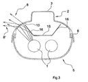
- FIG. 3 shows a cross section through an alternative embodiment of the lamp according to the invention. This is a two-lamp lamp. The corresponding components are denoted by the same reference numerals as in FIG FIG. 2 designated.
- a reflector 15 is arranged between the one or more lamps 1 of the lamp and the housing base part 5. A significant proportion of the light radiation from the light source (s) is directed by the reflector 15 in the direction of the transparent housing cover 5.
- laterally angled portions 16 are provided on the reflector 15, which also reflect light to the portions of the housing base part 2, which are provided with the refractive structures 10.
- the effect of the reflector sections 16 of the reflector 15 is based on the light beam 8 'in connection with FIG. 3 explained.
- the light radiation 8 ' which emanates from a luminous means 1 and is reflected at the reflector portion 16, impinges on the refractive structure 10 at a shallower angle compared to the light radiation which impinges on the same location but without reflection at the reflector portion 16.
- Due to the reflection in the reflector section 16, the light beam 8 ' is already deflected in the direction away from the luminaire mounting side 3 by reflection at the reflector section 16.
- This effect is reinforced by the subsequent refraction of the refractive structure 10 again.
- an even greater width distribution of the portion of the light distribution curve forming the indirect component 14 is produced by the light beam 8 '.
- the translucent portions of the housing base portion 2, which are provided with the refractive structures 10, are located relative to a cross section perpendicular to the longitudinal extent of the lamp above the one or more lamps 1 and below the mounting surface 3.
- an angular range of 5 ° to 85 °, preferably 20 ° to 80 °, above a flat sectional surface, parallel to the mounting side 3 and by the light source 1 for the arrangement of refractive structures preferred is preferred.
- the refractive structures 10 may also be formed with a different geometry in order to bring about the desired effect.
- the refractive structure may be provided on the outside of the luminaire.
Landscapes
- Engineering & Computer Science (AREA)
- General Engineering & Computer Science (AREA)
- Non-Portable Lighting Devices Or Systems Thereof (AREA)
Claims (13)
- Luminaire, comportant un boîtier comprenant une partie de base (2) et un couvercle (5) transparent, lesquels délimitent un volume intérieur du boîtier, au moins un moyen d'éclairage (1) étant disposé dans le volume intérieur du boîtier, la partie de base (2) du boîtier comportant au moins une portion qui est formée par un matériau transparent, à travers lequel passe la lumière du moyen d'éclairage pour générer un éclairage indirect, des structures réfractrices (10) étant disposées sur la portion transparente de la partie de base (2),
caractérisé en ce que la partie de base (2) du boîtier comporte, sur le côté opposé au moyen d'éclairage (1), un côté de fixation (3) pour fixer le luminaire, et la lumière passant à travers ladite portion transparente est déviée par les structures réfractrices (10) dans une direction s'écartant du côté de fixation (3). - Luminaire selon la revendication 1, dans lequel les structures réfractrices (10), sur une coupe transversale perpendiculairement à une direction longitudinale du moyen d'éclairage (1), possèdent une section transversale constante au moins sur une partie de la direction longitudinale.
- Luminaire selon la revendication 2, dans lequel l'épaisseur des structures réfractrices (10), respectivement dans ladite section transversale, diminue depuis le côté opposé au côté de fixation (3) vers le côté orienté vers le côté de fixation (3).
- Luminaire selon l'une quelconque des revendications précédentes, dans lequel les structures réfractrices (10) sont formées par des éléments prismatiques.
- Luminaire selon la revendication 4, dans lequel les éléments prismatiques comportent deux branches (11, 12) asymétriques.
- Luminaire selon l'une quelconque des revendications précédentes, dans lequel les structures réfractrices (10) sont disposées sur le côté, orienté vers le volume intérieur, de la partie de base du boîtier.
- Luminaire selon l'une quelconque des revendications précédentes, dans lequel la partie de base (2) du boîtier comporte au moins deux portions transparentes avec des structures réfractrices (10), qui sont disposées de part et d'autre du côté de fixation (3) de la partie de base (2) du boîtier.
- Luminaire selon l'une quelconque des revendications précédentes, dans lequel la partie de base (2) du boîtier est réalisée sensiblement en totalité dans un matériau transparent.
- Luminaire selon l'une quelconque des revendications précédentes, dans lequel un réflecteur (15) est agencé dans le volume intérieur du boîtier entre la partie de base (2) et le moyen d'éclairage (1).
- Luminaire selon la revendication 9, dans lequel la lumière du moyen d'éclairage (1) passe en ligne droite à côté du réflecteur (15) ou à travers une ouverture dans le réflecteur vers la portion transparente de la partie de base (2) du boîtier, au niveau de laquelle sont prévues les structures réfractrices.
- Luminaire selon la revendication 9 ou 10, dans lequel le réflecteur (15) comporte une ou plusieurs surfaces réfléchissantes (16) qui sont agencées de telle sorte qu'elles réfléchissent la lumière du moyen d'éclairage (1) vers la portion transparente de la partie de base (2) du boîtier.
- Luminaire selon la revendication 11, dans lequel le faisceau de lumière, qui est projeté via le réflecteur (15) sur la portion transparente de la partie de base (2) du boîtier, rencontre la portion transparente en formant avec le côté de fixation (3) de la partie de base (2) un angle plus plat que dans le cas d'un faisceau de lumière qui est projeté sur le même emplacement de la portion transparente sans réflexion sur le réflecteur (15), les angles étant déterminés dans une surface de section transversale perpendiculairement à une direction longitudinale du luminaire.
- Luminaire selon l'une quelconque des revendications précédentes, dans lequel le boîtier est entièrement fermé, il est étanché en particulier contre l'humidité, les projections d'eau ou les éclaboussures d'eau.
Applications Claiming Priority (1)
| Application Number | Priority Date | Filing Date | Title |
|---|---|---|---|
| DE102007053468 | 2007-11-09 |
Publications (2)
| Publication Number | Publication Date |
|---|---|
| EP2058587A1 EP2058587A1 (fr) | 2009-05-13 |
| EP2058587B1 true EP2058587B1 (fr) | 2011-12-28 |
Family
ID=40336618
Family Applications (1)
| Application Number | Title | Priority Date | Filing Date |
|---|---|---|---|
| EP08019624A Not-in-force EP2058587B1 (fr) | 2007-11-09 | 2008-11-10 | Lampe de cuve dotée d'une part indirecte de lumière |
Country Status (2)
| Country | Link |
|---|---|
| EP (1) | EP2058587B1 (fr) |
| AT (1) | ATE539297T1 (fr) |
Families Citing this family (2)
| Publication number | Priority date | Publication date | Assignee | Title |
|---|---|---|---|---|
| JP2015115220A (ja) * | 2013-12-12 | 2015-06-22 | 東芝ライテック株式会社 | 照明装置 |
| DE102014119616A1 (de) | 2014-12-23 | 2016-06-23 | Siteco Beleuchtungstechnik Gmbh | LED-Linsenkörper zur Erzeugung eines Direkt- und Indirektlichtanteils |
Family Cites Families (4)
| Publication number | Priority date | Publication date | Assignee | Title |
|---|---|---|---|---|
| DE7910659U1 (de) * | 1979-04-11 | 1979-07-12 | Siemens Ag, 1000 Berlin Und 8000 Muenchen | Pendelleuchte mit teilweise nach oben strahlender optik |
| DE29502183U1 (de) | 1995-02-10 | 1996-05-02 | Zumtobel Licht | Leuchte, insbesondere Feuchtraumleuchte, mit einem zweiteiligen geschlossenen Gehäuse |
| DE20314606U1 (de) * | 2003-09-18 | 2003-11-27 | Unger Patent- und Lizenzgesellschaft mbH | Direkt und indirekt abstrahlende Leuchte |
| EP1847766A1 (fr) * | 2006-04-18 | 2007-10-24 | Hartmut S. Engel | Dispositif d'éclairage intérieur |
-
2008
- 2008-11-10 EP EP08019624A patent/EP2058587B1/fr not_active Not-in-force
- 2008-11-10 AT AT08019624T patent/ATE539297T1/de active
Also Published As
| Publication number | Publication date |
|---|---|
| EP2058587A1 (fr) | 2009-05-13 |
| ATE539297T1 (de) | 2012-01-15 |
Similar Documents
| Publication | Publication Date | Title |
|---|---|---|
| EP1378771B1 (fr) | Eclairage intérieur | |
| DE10065020B4 (de) | Fahrzeugscheinwerfer | |
| EP2729838B1 (fr) | Élément optique | |
| EP2039985B1 (fr) | Dispositif d'éclairage DEL doté d'une répartition asymétrique de la lumière, en particulier pour éclairages publics | |
| DE102008060874A1 (de) | Leuchte | |
| EP1110031B1 (fr) | Lampe dotee d'un guide de lumiere | |
| EP2546565B1 (fr) | Encoche pour éclairage de plafond | |
| DE10109357A1 (de) | Beleuchtungseinrichtung für Fahrzeuge | |
| EP0802368A2 (fr) | Luminaire avec une lampe notamment a faible volume | |
| EP1679470B1 (fr) | Luminaire avec guide de lumière creux | |
| EP1770329A2 (fr) | Dispositif pour éviter de manière sélective l'éblouissement d'un éclairage extérieur selon un axe vertical et horizontal | |
| EP2058587B1 (fr) | Lampe de cuve dotée d'une part indirecte de lumière | |
| DE4312889B4 (de) | Vorwiegend direkt strahlende Leuchte mit einem abgehängten Lichtleitkörper | |
| DE10011378B4 (de) | Hohllichtleiterleuchte mit indirekter Lichtabstrahlung | |
| DE102006030646B4 (de) | Innenraumleuchte zur Ausleuchtung einer Wand oder Decke | |
| EP1608909B1 (fr) | Element influant sur la lumiere | |
| DE3841518A1 (de) | Spiegelrasterleuchte | |
| EP1845303B1 (fr) | Lampe avec réflecteurs de matière synthétique | |
| DE102012102652B4 (de) | Beleuchtungsanordnung mit Leuchtdioden | |
| DE102006047689B4 (de) | Leuchte und Lichtbandsystem mit transparentem Leuchtenschirm | |
| DE10354462B4 (de) | Leuchte mit asymmetrischer Lichtabstrahlung | |
| EP1843082B1 (fr) | Plafonnier, en particulier pour utilisation dans un couloir | |
| EP1900998B1 (fr) | Réflecteur doté d'une structure émettant de la lumière | |
| DE102017128893B4 (de) | Beleuchtungseinrichtung eines Kraftfahrzeugs | |
| DE19957811A1 (de) | Lichtleiterleuchte mit Abschirmung in zwei Ebenen |
Legal Events
| Date | Code | Title | Description |
|---|---|---|---|
| PUAI | Public reference made under article 153(3) epc to a published international application that has entered the european phase |
Free format text: ORIGINAL CODE: 0009012 |
|
| AK | Designated contracting states |
Kind code of ref document: A1 Designated state(s): AT BE BG CH CY CZ DE DK EE ES FI FR GB GR HR HU IE IS IT LI LT LU LV MC MT NL NO PL PT RO SE SI SK TR |
|
| AX | Request for extension of the european patent |
Extension state: AL BA MK RS |
|
| 17P | Request for examination filed |
Effective date: 20091016 |
|
| 17Q | First examination report despatched |
Effective date: 20091113 |
|
| AKX | Designation fees paid |
Designated state(s): AT BE BG CH CY CZ DE DK EE ES FI FR GB GR HR HU IE IS IT LI LT LU LV MC MT NL NO PL PT RO SE SI SK TR |
|
| GRAP | Despatch of communication of intention to grant a patent |
Free format text: ORIGINAL CODE: EPIDOSNIGR1 |
|
| GRAS | Grant fee paid |
Free format text: ORIGINAL CODE: EPIDOSNIGR3 |
|
| GRAA | (expected) grant |
Free format text: ORIGINAL CODE: 0009210 |
|
| RAP1 | Party data changed (applicant data changed or rights of an application transferred) |
Owner name: SITECO BELEUCHTUNGSTECHNIK GMBH |
|
| AK | Designated contracting states |
Kind code of ref document: B1 Designated state(s): AT BE BG CH CY CZ DE DK EE ES FI FR GB GR HR HU IE IS IT LI LT LU LV MC MT NL NO PL PT RO SE SI SK TR |
|
| REG | Reference to a national code |
Ref country code: GB Ref legal event code: FG4D Free format text: NOT ENGLISH |
|
| REG | Reference to a national code |
Ref country code: CH Ref legal event code: EP |
|
| REG | Reference to a national code |
Ref country code: AT Ref legal event code: REF Ref document number: 539297 Country of ref document: AT Kind code of ref document: T Effective date: 20120115 |
|
| REG | Reference to a national code |
Ref country code: IE Ref legal event code: FG4D |
|
| REG | Reference to a national code |
Ref country code: CH Ref legal event code: NV Representative=s name: ISLER & PEDRAZZINI AG |
|
| REG | Reference to a national code |
Ref country code: DE Ref legal event code: R096 Ref document number: 502008005978 Country of ref document: DE Effective date: 20120308 |
|
| REG | Reference to a national code |
Ref country code: NL Ref legal event code: VDEP Effective date: 20111228 |
|
| REG | Reference to a national code |
Ref country code: CH Ref legal event code: PUE Owner name: SITECO BETEILIGUNGSVERWALTUNGS GMBH Free format text: SITECO BELEUCHTUNGSTECHNIK GMBH#GEORG-SIMON-OHM-STRASSE 50#83301 TRAUNREUT (DE) -TRANSFER TO- SITECO BETEILIGUNGSVERWALTUNGS GMBH#GEORG-SIMON-OHM-STR. 50#83301 TRAUNREUT (DE) |
|
| REG | Reference to a national code |
Ref country code: NO Ref legal event code: T2 Effective date: 20111228 |
|
| PG25 | Lapsed in a contracting state [announced via postgrant information from national office to epo] |
Ref country code: LT Free format text: LAPSE BECAUSE OF FAILURE TO SUBMIT A TRANSLATION OF THE DESCRIPTION OR TO PAY THE FEE WITHIN THE PRESCRIBED TIME-LIMIT Effective date: 20111228 |
|
| REG | Reference to a national code |
Ref country code: CH Ref legal event code: PFA Owner name: SITECO BELEUCHTUNGSTECHNIK GMBH Free format text: SITECO BETEILIGUNGSVERWALTUNGS GMBH#GEORG-SIMON-OHM-STR. 50#83301 TRAUNREUT (DE) -TRANSFER TO- SITECO BELEUCHTUNGSTECHNIK GMBH#GEORG-SIMON-OHM-STR. 50#83301 TRAUNREUT (DE) |
|
| LTIE | Lt: invalidation of european patent or patent extension |
Effective date: 20111228 |
|
| REG | Reference to a national code |
Ref country code: FR Ref legal event code: TP Owner name: SITECO BELEUCHTUNGSTECHNIK GMBH, DE Effective date: 20120425 Ref country code: FR Ref legal event code: CD Owner name: SITECO BELEUCHTUNGSTECHNIK GMBH, DE Effective date: 20120425 |
|
| PG25 | Lapsed in a contracting state [announced via postgrant information from national office to epo] |
Ref country code: SE Free format text: LAPSE BECAUSE OF FAILURE TO SUBMIT A TRANSLATION OF THE DESCRIPTION OR TO PAY THE FEE WITHIN THE PRESCRIBED TIME-LIMIT Effective date: 20111228 Ref country code: SI Free format text: LAPSE BECAUSE OF FAILURE TO SUBMIT A TRANSLATION OF THE DESCRIPTION OR TO PAY THE FEE WITHIN THE PRESCRIBED TIME-LIMIT Effective date: 20111228 Ref country code: LV Free format text: LAPSE BECAUSE OF FAILURE TO SUBMIT A TRANSLATION OF THE DESCRIPTION OR TO PAY THE FEE WITHIN THE PRESCRIBED TIME-LIMIT Effective date: 20111228 Ref country code: HR Free format text: LAPSE BECAUSE OF FAILURE TO SUBMIT A TRANSLATION OF THE DESCRIPTION OR TO PAY THE FEE WITHIN THE PRESCRIBED TIME-LIMIT Effective date: 20111228 Ref country code: GR Free format text: LAPSE BECAUSE OF FAILURE TO SUBMIT A TRANSLATION OF THE DESCRIPTION OR TO PAY THE FEE WITHIN THE PRESCRIBED TIME-LIMIT Effective date: 20120329 |
|
| PG25 | Lapsed in a contracting state [announced via postgrant information from national office to epo] |
Ref country code: CY Free format text: LAPSE BECAUSE OF FAILURE TO SUBMIT A TRANSLATION OF THE DESCRIPTION OR TO PAY THE FEE WITHIN THE PRESCRIBED TIME-LIMIT Effective date: 20111228 |
|
| REG | Reference to a national code |
Ref country code: IE Ref legal event code: FD4D |
|
| PG25 | Lapsed in a contracting state [announced via postgrant information from national office to epo] |
Ref country code: BG Free format text: LAPSE BECAUSE OF FAILURE TO SUBMIT A TRANSLATION OF THE DESCRIPTION OR TO PAY THE FEE WITHIN THE PRESCRIBED TIME-LIMIT Effective date: 20120328 Ref country code: SK Free format text: LAPSE BECAUSE OF FAILURE TO SUBMIT A TRANSLATION OF THE DESCRIPTION OR TO PAY THE FEE WITHIN THE PRESCRIBED TIME-LIMIT Effective date: 20111228 Ref country code: IS Free format text: LAPSE BECAUSE OF FAILURE TO SUBMIT A TRANSLATION OF THE DESCRIPTION OR TO PAY THE FEE WITHIN THE PRESCRIBED TIME-LIMIT Effective date: 20120428 Ref country code: NL Free format text: LAPSE BECAUSE OF FAILURE TO SUBMIT A TRANSLATION OF THE DESCRIPTION OR TO PAY THE FEE WITHIN THE PRESCRIBED TIME-LIMIT Effective date: 20111228 Ref country code: EE Free format text: LAPSE BECAUSE OF FAILURE TO SUBMIT A TRANSLATION OF THE DESCRIPTION OR TO PAY THE FEE WITHIN THE PRESCRIBED TIME-LIMIT Effective date: 20111228 Ref country code: IE Free format text: LAPSE BECAUSE OF FAILURE TO SUBMIT A TRANSLATION OF THE DESCRIPTION OR TO PAY THE FEE WITHIN THE PRESCRIBED TIME-LIMIT Effective date: 20111228 Ref country code: CZ Free format text: LAPSE BECAUSE OF FAILURE TO SUBMIT A TRANSLATION OF THE DESCRIPTION OR TO PAY THE FEE WITHIN THE PRESCRIBED TIME-LIMIT Effective date: 20111228 |
|
| PG25 | Lapsed in a contracting state [announced via postgrant information from national office to epo] |
Ref country code: RO Free format text: LAPSE BECAUSE OF FAILURE TO SUBMIT A TRANSLATION OF THE DESCRIPTION OR TO PAY THE FEE WITHIN THE PRESCRIBED TIME-LIMIT Effective date: 20111228 Ref country code: PL Free format text: LAPSE BECAUSE OF FAILURE TO SUBMIT A TRANSLATION OF THE DESCRIPTION OR TO PAY THE FEE WITHIN THE PRESCRIBED TIME-LIMIT Effective date: 20111228 Ref country code: PT Free format text: LAPSE BECAUSE OF FAILURE TO SUBMIT A TRANSLATION OF THE DESCRIPTION OR TO PAY THE FEE WITHIN THE PRESCRIBED TIME-LIMIT Effective date: 20120430 |
|
| PG25 | Lapsed in a contracting state [announced via postgrant information from national office to epo] |
Ref country code: DK Free format text: LAPSE BECAUSE OF FAILURE TO SUBMIT A TRANSLATION OF THE DESCRIPTION OR TO PAY THE FEE WITHIN THE PRESCRIBED TIME-LIMIT Effective date: 20111228 |
|
| PLBE | No opposition filed within time limit |
Free format text: ORIGINAL CODE: 0009261 |
|
| STAA | Information on the status of an ep patent application or granted ep patent |
Free format text: STATUS: NO OPPOSITION FILED WITHIN TIME LIMIT |
|
| 26N | No opposition filed |
Effective date: 20121001 |
|
| REG | Reference to a national code |
Ref country code: DE Ref legal event code: R097 Ref document number: 502008005978 Country of ref document: DE Effective date: 20121001 |
|
| PG25 | Lapsed in a contracting state [announced via postgrant information from national office to epo] |
Ref country code: ES Free format text: LAPSE BECAUSE OF FAILURE TO SUBMIT A TRANSLATION OF THE DESCRIPTION OR TO PAY THE FEE WITHIN THE PRESCRIBED TIME-LIMIT Effective date: 20120408 |
|
| BERE | Be: lapsed |
Owner name: SITECO BELEUCHTUNGSTECHNIK G.M.B.H. Effective date: 20121130 |
|
| PG25 | Lapsed in a contracting state [announced via postgrant information from national office to epo] |
Ref country code: FI Free format text: LAPSE BECAUSE OF FAILURE TO SUBMIT A TRANSLATION OF THE DESCRIPTION OR TO PAY THE FEE WITHIN THE PRESCRIBED TIME-LIMIT Effective date: 20111228 |
|
| PG25 | Lapsed in a contracting state [announced via postgrant information from national office to epo] |
Ref country code: BE Free format text: LAPSE BECAUSE OF NON-PAYMENT OF DUE FEES Effective date: 20121130 |
|
| PG25 | Lapsed in a contracting state [announced via postgrant information from national office to epo] |
Ref country code: MT Free format text: LAPSE BECAUSE OF FAILURE TO SUBMIT A TRANSLATION OF THE DESCRIPTION OR TO PAY THE FEE WITHIN THE PRESCRIBED TIME-LIMIT Effective date: 20111228 |
|
| PG25 | Lapsed in a contracting state [announced via postgrant information from national office to epo] |
Ref country code: MC Free format text: LAPSE BECAUSE OF NON-PAYMENT OF DUE FEES Effective date: 20121130 |
|
| PG25 | Lapsed in a contracting state [announced via postgrant information from national office to epo] |
Ref country code: LU Free format text: LAPSE BECAUSE OF NON-PAYMENT OF DUE FEES Effective date: 20121110 |
|
| PG25 | Lapsed in a contracting state [announced via postgrant information from national office to epo] |
Ref country code: HU Free format text: LAPSE BECAUSE OF FAILURE TO SUBMIT A TRANSLATION OF THE DESCRIPTION OR TO PAY THE FEE WITHIN THE PRESCRIBED TIME-LIMIT Effective date: 20081110 |
|
| REG | Reference to a national code |
Ref country code: FR Ref legal event code: PLFP Year of fee payment: 8 |
|
| REG | Reference to a national code |
Ref country code: FR Ref legal event code: PLFP Year of fee payment: 9 |
|
| REG | Reference to a national code |
Ref country code: FR Ref legal event code: PLFP Year of fee payment: 10 |
|
| PGFP | Annual fee paid to national office [announced via postgrant information from national office to epo] |
Ref country code: TR Payment date: 20171109 Year of fee payment: 10 Ref country code: NO Payment date: 20171124 Year of fee payment: 10 Ref country code: FR Payment date: 20171121 Year of fee payment: 10 |
|
| PGFP | Annual fee paid to national office [announced via postgrant information from national office to epo] |
Ref country code: AT Payment date: 20171121 Year of fee payment: 10 Ref country code: GB Payment date: 20171123 Year of fee payment: 10 Ref country code: CH Payment date: 20171120 Year of fee payment: 10 Ref country code: IT Payment date: 20171124 Year of fee payment: 10 |
|
| REG | Reference to a national code |
Ref country code: NO Ref legal event code: MMEP |
|
| REG | Reference to a national code |
Ref country code: CH Ref legal event code: PL |
|
| REG | Reference to a national code |
Ref country code: AT Ref legal event code: MM01 Ref document number: 539297 Country of ref document: AT Kind code of ref document: T Effective date: 20181110 |
|
| GBPC | Gb: european patent ceased through non-payment of renewal fee |
Effective date: 20181110 |
|
| PG25 | Lapsed in a contracting state [announced via postgrant information from national office to epo] |
Ref country code: NO Free format text: LAPSE BECAUSE OF NON-PAYMENT OF DUE FEES Effective date: 20181130 |
|
| PG25 | Lapsed in a contracting state [announced via postgrant information from national office to epo] |
Ref country code: LI Free format text: LAPSE BECAUSE OF NON-PAYMENT OF DUE FEES Effective date: 20181130 Ref country code: CH Free format text: LAPSE BECAUSE OF NON-PAYMENT OF DUE FEES Effective date: 20181130 |
|
| PG25 | Lapsed in a contracting state [announced via postgrant information from national office to epo] |
Ref country code: FR Free format text: LAPSE BECAUSE OF NON-PAYMENT OF DUE FEES Effective date: 20181130 Ref country code: AT Free format text: LAPSE BECAUSE OF NON-PAYMENT OF DUE FEES Effective date: 20181110 Ref country code: IT Free format text: LAPSE BECAUSE OF NON-PAYMENT OF DUE FEES Effective date: 20181110 |
|
| PG25 | Lapsed in a contracting state [announced via postgrant information from national office to epo] |
Ref country code: GB Free format text: LAPSE BECAUSE OF NON-PAYMENT OF DUE FEES Effective date: 20181110 |
|
| REG | Reference to a national code |
Ref country code: DE Ref legal event code: R082 Ref document number: 502008005978 Country of ref document: DE Representative=s name: BOEHMERT & BOEHMERT ANWALTSPARTNERSCHAFT MBB -, DE Ref country code: DE Ref legal event code: R081 Ref document number: 502008005978 Country of ref document: DE Owner name: SITECO GMBH, DE Free format text: FORMER OWNER: SITECO BELEUCHTUNGSTECHNIK GMBH, 83301 TRAUNREUT, DE |
|
| PGFP | Annual fee paid to national office [announced via postgrant information from national office to epo] |
Ref country code: DE Payment date: 20211122 Year of fee payment: 14 |
|
| PG25 | Lapsed in a contracting state [announced via postgrant information from national office to epo] |
Ref country code: TR Free format text: LAPSE BECAUSE OF NON-PAYMENT OF DUE FEES Effective date: 20181110 |
|
| REG | Reference to a national code |
Ref country code: DE Ref legal event code: R119 Ref document number: 502008005978 Country of ref document: DE |
|
| PG25 | Lapsed in a contracting state [announced via postgrant information from national office to epo] |
Ref country code: DE Free format text: LAPSE BECAUSE OF NON-PAYMENT OF DUE FEES Effective date: 20230601 |