EP2058262B2 - Braking device for braking a cabin - Google Patents
Braking device for braking a cabin Download PDFInfo
- Publication number
- EP2058262B2 EP2058262B2 EP07021915.9A EP07021915A EP2058262B2 EP 2058262 B2 EP2058262 B2 EP 2058262B2 EP 07021915 A EP07021915 A EP 07021915A EP 2058262 B2 EP2058262 B2 EP 2058262B2
- Authority
- EP
- European Patent Office
- Prior art keywords
- pawl
- brake
- brake module
- braking
- operating position
- Prior art date
- Legal status (The legal status is an assumption and is not a legal conclusion. Google has not performed a legal analysis and makes no representation as to the accuracy of the status listed.)
- Active
Links
Images


Classifications
-
- B—PERFORMING OPERATIONS; TRANSPORTING
- B66—HOISTING; LIFTING; HAULING
- B66B—ELEVATORS; ESCALATORS OR MOVING WALKWAYS
- B66B5/00—Applications of checking, fault-correcting, or safety devices in elevators
- B66B5/02—Applications of checking, fault-correcting, or safety devices in elevators responsive to abnormal operating conditions
- B66B5/16—Braking or catch devices operating between cars, cages, or skips and fixed guide elements or surfaces in hoistway or well
- B66B5/18—Braking or catch devices operating between cars, cages, or skips and fixed guide elements or surfaces in hoistway or well and applying frictional retarding forces
Definitions
- the invention relates to a braking device for braking a car, an elevator system and a method for adjusting at least one brake module.
- spring systems can be used.
- An example of this are spring brakes with coil springs, as in the case of the document DE 197 19 079 C1 used in crane or other industrial plants.
- spring brakes are relatively heavy and require a noisy pneumatic or hydraulic vent that is susceptible to leakage and / or contamination and thus does not allow the use of safe drives to ventilate these brakes.
- One from the publication DE 202 16 046 U1 known braking device comprises a disc brake, but which can also be used as a linear brake, wherein the braking force is applied directly from lever arms.
- this braking device is provided that the complete ventilation system does not include self-locking components, so as to meet the requirement of a safety brake.
- spring arrangements to provide large air gaps require a high release force, also an incidence time is long in case of failure of the power supply.
- a braking device with which a large air gap can be realized is in the document DE 100 15 263 A1 described.
- linear movements of a drive unit are used, so that brake pads this braking device can cover relatively large distances.
- a linear unit is used here simultaneously to generate a contact force for the brake pads.
- this braking device has no fail-safe function.
- So-called safety gears with which an instantaneous stopping can be brought about, are realized in the present state of the art by so-called wedge brakes.
- wedge brakes This is, as for example in the document EP 1 719 730 A1 described, a brake wedge applied via a mating surface to the rail of an elevator system by the resulting friction on the rail, a mating surface of the brake wedge is further retracted and thus generates the required contact force to decelerate the car.
- Energy that is stored by springs or weights is used here only to safely retract the brake wedge so that it generates the braking force due to the geometry and the kinematics of the entire system.
- Such safety gears usually generate the required braking energy by frictional forces being generated by the brake wedge or its mating surface on the rail.
- Another method to reduce the kinetic energy of the car is that the brake wedge or counter surface make deformation work on a rail of the elevator system. As a result, large amounts of energy can be broken down relatively easily.
- the invention relates to a braking device for braking a car moving relative to a hoistway, comprising at least one brake module intended to cooperate with a device moving relative to the brake module, and having a pawl adjustable between two operating positions, the pawl in a first operating position with the at least one brake module is connected such that from the pawl on the at least one brake module, a release force is transmitted, and wherein the pawl is separated in a second operating position of the at least one brake module, so that the at least one brake module with the device is in contact.
- This braking device is also designed to realize an emergency braking in the second operating position of the pawl as an embodiment of a braking, so that the braking device can also be referred to as a so-called safety gear.
- the first operating position is provided that by regulating the release force a width of a gap between the at least one brake module and the device is adjustable, so that a braking force can be adjusted in a suitable manner. Accordingly, it is also possible to allow in the first operating position an unrestricted ride of the car.
- the device is designed as a stationary device, for example as a rail of an elevator system.
- a movement of the car can be braked with the braking device and intercepted.
- the braking device is arranged stationary relative to the elevator shaft.
- the brake module is configured to cooperate with a moving device.
- the moving device is, for example, as a suspension means, e.g. as a rope or a set of ropes. About such a suspension means of the car is moved within the elevator shaft.
- the brake device has at least one drive for providing and varying the release force.
- the braking device may have, for example, a holding device designed as an electromagnet, which is designed to hold the pawl in the first operating position.
- the electromagnet holds the pawl in an energized state in the first operating position.
- the electromagnet can be supplied with electrical energy, which is provided, for example.
- the brake device may comprise at least one lever which is adapted to set a distance between the brake module and the device.
- the braking device has at least one, for example. Designed as a spring, power module and / or energy storage, which is and / or is adapted to provide a braking force for the at least one brake module.
- the braking force of the release force vectorially counteracts.
- the at least one brake module may include as a component a counterpart adapted to cooperate with the pawl, the pawl being engaged with the counterpart in the first operative position.
- the braking device can have at least one latching aid, which is designed to transfer the latch, for example, automatically and / or electromechanically from the second operating position into the first operating position.
- the elevator installation according to the invention has at least one braking device described above and at least one car.
- the invention also relates to a method for adjusting at least one brake module for a car moving relative to a hoistway, wherein the at least one brake module is intended to cooperate with a device.
- a pawl is switched back and forth between two operating positions, wherein the pawl is connected in a first operating position with the at least one brake module such that a release force is transmitted from the pawl to the at least one brake module, and wherein the at least one brake module and the pawl are separated from each other when switching to the second operating position, so that the at least one brake module is in contact with the device.
- a width of a clearance between the device and the at least one brake module is regulated by changing the release force, so that the car is braked.
- a change in the release force causes application of the brake pads on the device.
- a defined braking force can be provided.
- the at least one brake module is in contact with the device such that the car is stopped or emergency braked.
- At least one step of the method according to the invention can be carried out by the braking device according to the invention or by at least one component of this braking device.
- a function of at least one component of the braking device or the braking device itself can be realized as a step of the presented method.
- the brake device comprises at least one brake module that can interact with at least one device and usually with at least one pawl.
- a safety brake can be realized, in which a collapse of the brake by a latch mechanism, which may include the pawl, can be triggered.
- the pawl is moved by a drive module or a drive as a component of a latch mechanism, whereby the at least one brake module can be opened and closed, wherein such a drive may also be designed as a Lsymmetricantrieb the braking device can.
- a release force of the brake device wherein this release force is provided, inter alia, by an interaction of the pawl and the electromagnet such that the brake module is spaced from the device to provide the air gap, can by the pawl to be interrupted.
- the pawl is designed as a transmission means for providing an interaction between the drive module and the brake module.
- the at least one latch mechanism may, for example, also have an energy store which is suitable for applying a force by means of which the pawl can be hooked onto the brake module, so that the pawl, after such a hooking up, starts again from the second operating position in the first Operating position and is provided between the brake module and the device of the air gap.
- an additional gear can be arranged.
- the latch mechanism can have an independent and / or automatic latching aid or latching unit.
- the brake device During operation of the brake device, it is provided that when the electromagnet is switched off, i. Interruption of the energization of the electromagnet, the pawl is incident and thus separates from the brake module. As long as the electromagnet is energized or is, the pawl is held in the first operating position. At the moment when the electromagnet is no longer energized, the solenoid can no longer magnetically attract the pawl, so that the pawl releases from the electromagnet and thus simultaneously separates from the brake module.
- pawl mechanism for the appropriate positioning of the pawl in a respective operating position may be formed such that braking operations to be performed by the braking device in a conventional manner are not affected.
- the braking device may have a self-locking drive and / or a self-locking gear as a possible component of the latch mechanism.
- the latching mechanism typically does not have self-locking elements for braking.
- the latch In the first operating position, the latch u.a. be supplemented by a self-locking gear and a drive.
- Airing the brake device and in particular of the brake module of the brake device, which usually takes place when the pawl is in the first operating position, may be provided in a design as a so-called symmetrical ventilation, which is also possible with motorized ventilation.
- a described symmetrical lifting can be realized by controlling at least one lever as a component of the latch mechanism, wherein such a lever is inserted in at least one fixed point.
- a translation of the venting force provided for ventilation is possible.
- a Lsterweg be realized by an eccentricity of the at least one lever.
- the latch mechanism described or a corresponding device for ventilation can also be used to ventilate additional brake modules.
- the brake device can be designed such that a transition of the pawl from the first operating position to the second operating position takes place in a short period of time and thus jerkily.
- a suitably dimensioned energy store in particular a spring which is designed to act on the brake module
- the air gap between the brake module and the device can be closed immediately via a sufficiently large contact force, so that u.a.
- An emergency braking can be performed, so that the braking device can be referred to in this aspect as a safety gear.
- a safety gear is also triggered by changing the operating position of the pawl and a consequent change in position or position of the brake module relative to the device and thus activated.
- An emergency braking and thus catching the moving car relative to the elevator shaft can be done in several directions.
- the particular stationary device is formed as a rail of an elevator system, it is possible that both an upward and a downward movement of the car can be stopped quickly and safely by the braking device.
- a downward movement of the car can be effectively braked or stopped when the brake module interacts in particular with a downwardly moving strand of the suspension element.
- An upward movement of the car is thereby effectively braked or stopped by the brake module interacts in particular with an upwardly moving strand of the support means.
- a braking or stopping a movement of the car can be independent of direction by interaction of any section or strand of the suspension element with the brake module.
- the braking device in particular if it is designed to catch the car, have a trained as a catch wedge brake module, wherein such a catch wedge cooperates with a unit for retraction, which in turn can be triggered by the pawl in the transition to the second operating position , so that the emergency stop can be brought about the catch wedge.
- the generation of the braking force can then take place by a wedging action of the catching wedge.
- a brake device with a large air gap for braking and / or catching a car can be realized.
- This brake device falls completely due to the compression spring for applying the brake module and the use of the electromagnet for holding the pawl in case of failure of the supply energy completely. It is thus safe in all operating situations (fail-safe).
- a lever control as a component of the pawl mechanism, a translation between a L850motor as a drive of the latch mechanism and on the release force, which acts on the acted upon by the spring brake module can be adjusted.
- the lever control allows u.a. a symmetrical airing.
- the braking device can be opened and closed by a motor for braking. It is usually provided that the release force, which is generated via a suitable movement of the drive is transmitted from the drive via the pawl as a means for transmitting the release force to the brake module.
- brake modules which may have brake shoes or brake pads, motorized to the device, for example.
- Rail create an impact velocity of the brake pads can be controlled on the rail.
- an incident speed and the noise level at the time of engagement of the pawl and thus the brake module can be regulated.
- electromagnet as emergency release for the pawl and non-safe drives for releasing the brake can be used.
- the incidence time is much lower by the latch mechanism. This results in that a free fall of the car in case of power failure can not take place or only very briefly.
- a brake without independent provision of the pawl brake device described meets the essential requirements for safety gear for lifts to EN 81. Due to a release by the electromagnet very small incidence times are possible.
- the collapse of the brake device can be additionally regulated by a motor which acts on the pawl, with several speed levels.
- a braking device can be found in elevator construction as a so-called rail brake.
- the car to his guide rails usually a significant game.
- the Lifts Directive and EN 81 require a so-called fail-safe, i. failsafe or fail-safe braking systems to prevent crash of the car or cab with very high safety.
- a braking system must be used, which combines large gaps and the fail-safe safety aspect.
- the braking device can be realized, for example, as a rail brake; this results in that the braking force is not generated in the engine room, but on the car, ie directly where it is needed.
- the brake device can be used by the latch mechanism as a safety gear in lifts. Furthermore, a combination of brake device and safety gear in the brake device is possible. This results, for example., That when both systems, i. the brake and the safety gear, do not affect extremely high delays on passengers in the car.
- a lift catcher can be realized with trip units having centrifugal forces to detect an overspeed of the car. These trip units can hang with their flyweights and thus trigger the safety gear by moving the pawl from the first to the second operating position.
- the brake is possible in the field of construction machinery, in the underground and in the complete rail-bound conveying area. Due to the large air gap, the brake can be used in environments with heavy pollution.
- the fail-safe system provided in the context of the invention here also increases the reliability and safety of the arrangement described.
- the invention therefore relates inter alia to a braking device for braking or for deceleration and / or for fixing movements of cars.
- the braking of rail-bound conveying means in particular elevators, in this case takes place by friction on a stationary rail running parallel to the conveying direction as a stationary device.
- the same application is also possible for braking rotational movements on a brake disk as a device.
- the friction linings of the brake module are moved approximately perpendicular to the path of the rail from a release position and thus the first operating position into a braking position and thus the second operating position. This initiates a braking process.
- a variant of the brake device has a brake pad as a brake module.
- the braking force is generated or amplified via a wedge.
- This wedge can be moved over its counter surface and thus at an angle less than 90 ° to the rail and therefore not perpendicular to the rail track applied.
- the force required for friction contact pressure of the brake module is generated against the device.
- the full braking force is provided.
- the movement from the braking position into the release position takes place with energy absorption of the braking device or of a corresponding overall system.
- a flow of the spring force is in this case diverted in the region of at least one, for example, designed as a brake shoe brake module.
- the spring force is bridged by means of the lever control.
- An embodiment of the braking device provides an arrangement of a lever without a fixed point.
- the Lsterweg and thus air gap is generated by an eccentricity of the lever.
- a force application point can therefore lie outside a plane of the device and thus, for example, the rail. This saves, for example, when using two levers, the provision of an intermediate piece.
- a transmission ratio of generated to required release force can be provided.
- the power generation for releasing the brake module can be generated by an electric motor, hydraulically, pneumatically or by other energy converters.
- a translation through a gear is possible.
- a drive can also be used to ventilate multiple brake modules for braking and / or catching.
- Self-locking components can be used in this area to save energy supply, without affecting the safety function of the brake device and therefore also of the brake module. At the end of this drive and gear unit typically creates a linear motion, which is transmitted to the pawl.
- Each of these two states or these two operating positions can be reliably detected by appropriate information sources and processed by a controller as another component of the braking device. This can be realized for example by switches in the end positions, measuring elements or by stepper motors.
- the drop in the release force can be realized in non-inhibiting systems that the generation of the release force is interrupted.
- a first variant is to reverse the release force generated by the drive in their effective direction, which is also possible for self-locking systems.
- the second variant is based on an interruption of the power flow through the latch by this is folded down. For this purpose, the electromagnet, which holds the pawl in its position, de-energized.
- the pawl By the weight of the pawl, a correspondingly shaped shape pairing between the pawl and counterpart of the brake module or by energy from previously strained elements, such as springs or other energy storage or energy converters, the pawl is brought out of position. A combination of these possibilities is also possible.
- two brake modules can be used, so that a safety rail brake with a rail depth of about 50 mm and a rail thickness of about 16 mm is realized.
- the braking device for braking With the braking device for braking a plurality of tripping speeds can be realized due to the structure with motor operation and latch release. Through the use of the electromagnet, the braking device for braking as a safety device for overspeed is down and up for conventional cable lifts alike suitable.
- the electromagnet can be designed as a safety magnet to be supplied with 12V.
- the braking device can be used as a braking, holding and safety gear. As a result, maximum delays to the passenger at the simultaneous incidence of all brake modules can be significantly reduced.
- the braking device can also be used for an unsafe drive, whereby an incident speed can be controlled and a symmetrical release behavior can be controlled.
- a fixation of the motor as a drive of the latch mechanism is to be constructed depending on the installation situation.
- a bolt at the rear end of, for example, designed as a motor drive can, for example, be firmly fixed.
- a bolt connecting the pawl and the motor can be linearly guided to receive the power of the motor.
- the described invention can u. a. be used as safety gear and / or safety brake. With the pawl a tensile and / or compressive force transmission is possible. In the context of the invention, the braking force can be adjusted by the release force. Furthermore, use of the brake device as a rope brake is possible, in this case it is provided that the brake module is fixed and is in contact with a moving rope as a device to effect a braking. In a further embodiment, the braking device can also be used for braking rotational movements of rotating devices.
- FIG. 1 schematically from above shown first embodiment of a brake device 2A for braking a car comprises a pawl 4A and two brake shoes designed as brake modules 6A, which are connected to a common counterpart 8A, said counterpart 8A in the in FIG. 1 shown first operating position with the pawl 4A in contact.
- the car along a rail 16A as a device can perform a movement.
- a "car” is to be understood as any kind of "vehicle” for transporting goods moving relative to a hoistway.
- the two brake modules 6A are spaced from the rail 16A by a spring 10A and two levers 12A respectively mounted on a wall 14A via pivot points 28A to form two symmetrical air gaps 18A.
- an electromagnet 20A pulls the pawl 4A upwards (ie against gravity).
- This measure makes it possible for the brake modules 6A to be connected to the pawl 4A via the counterpart 8A.
- a required for this purpose symbolized by an arrow release force 22A, is provided by a not shown here drive a latch mechanism by reciprocating the pawl 4A.
- the brake modules 6A are held in a position and, if necessary, moved relative to the rail 16A.
- the brake modules 6A designed with friction linings are lifted off the rail 16A.
- first operating position is provided in case of failure of energization of the electromagnet 20A, that the pawl 4A from the electromagnet 20A and thus also from the counterpart 8A, in which the pawl is hooked 4A dissolves, and moves to a second operating position.
- the two brake modules 6A their in FIG. 1 leave shown positions and are pressed by the spring 10A against the rail 16A and thus cause a braking of the car here not shown relative to the rail 16A.
- the release force 22A is no longer transmitted by a change in position of the pawl 4A and the brake modules 6A fall due to a fail-safe function of the brake device 2A a. This applies due to the use of the electromagnet 20A even when the supply voltage.
- An alternative to this is provided by a functional model of a latch mechanism for pulling air forces.
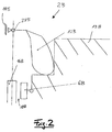
- FIG. 2 A detail of a second embodiment of a brake device 2B is shown in FIG. 2 shown schematically.
- a brake module 6B and a lever 12B, which is hinged to a wall 14B about a pivot point 28B, shown.
- the lever 12B cooperates with a force accumulator 13B such that the brake module 6B remains in the position shown here.
- the brake module 6B is further spaced from a rail 16B to form a release gap 18B.
- the lever 12B has no fixed pivot point.
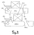
- FIG. 3 shows in a schematic representation in its upper portion a first example of a pawl 4C, which has an arm 24C with an inclined end 26C.
- This first example of the pawl 4C is adapted to cooperate with a counterpart 8C, which is connected to at least one brake module, not shown here.
- a second example of a pawl 40C includes an arm 240C having a rounded end 260C (see lower portion of Figs FIG. 3 ).
- This second example of the pawl 40C is adapted to engage with a counterpart 80C which is provided with at least one in FIG. 3 not shown brake module is connected to cooperate.
- FIG. 3 Electromagnet 20C, which are each energized and thus attract the pawls 4C, 40C, so that for both pawls 4C, 40C respectively, the first operating position is realized.
- the pawls 4C, 40C and in particular the arms 24C, 240C of the pawls 4CV, 40C may have different shapes and combinations of geometries, not shown.
- the pawls 4C, 40C are rotatably supported via pivot points 28c relative to a wall 14C.
- a release force through which a gap between the brake modules and an in FIG. 3 is not shown, is transmitted via the pawls 4C, 40C.
- the two electromagnets 20C hold the pawls 4C, 40C in their respective positions.
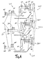
- FIG. 4 shows a schematic representation of a fourth embodiment of a braking device 2D with a pawl 4D, which is rotatable about a pivot point 28D relative to a wall 14D. It is also in FIG. 4 a solenoid 20D is also shown attached to the wall 14D.
- a solenoid 20D is also shown attached to the wall 14D.
- the fourth embodiment of the braking device 2D according to the invention also has at least one counterpart 8D, which is connected to at least one further brake module not shown here.
- the pawl 4D is connected to the wall 14D via a spring or other energy storage device 10D.
- the pawl 4D is pulled upwards by the electromagnet 20D, so that the pawl 4D is connected to the counterpart 8D and thus the at least one brake module connected to the counterpart 8D is released with the formation of a clearance with a stationary device.
- the electromagnet 20D is released from a current source, for example in the event of a power failure, the pawl 4D snaps down so that the connection of the pawl 4D to the counterpart 8D is disconnected and braking is initiated for the at least one brake module at least one brake module contacts the stationary device to generate friction.
- the spring 10D By providing the spring 10D, jamming of the pawl 4D is prevented because the release force acts on the pawl 4D from right and left. A weight force of the pawl 4D counteracts a frictional force. In order to ensure release of the brake device 2D, it is provided here that the spring 10D is compressed between the pawl 4D and the wall 14D, so that a spring force of the spring 10D acts downward. Once the solenoid 20D is de-energized, the pawl 4D disengages and falls down, urged by the spring 10D.
- FIG. 5 shows a schematic representation of a fifth embodiment of a brake device 2E with a latch mechanism, which is designed for tensile forces.
- This fifth embodiment of the brake device 2E comprises a pawl 4E with an arm 24E, at the end of which an arc 30E is arranged, wherein this arc 30E has at one end a ball 32E.
- the arm 24E of the pawl 4E is slidably and rotatably fixed via a pivot 28E relative to a wall 14E.
- On the wall 14E is also an electromagnet 20E fixed in the in FIG. 5 shown operating position is energized and thus the latch 4E pulls up.
- Via a further pivot point 29E is a counterpart 8E of a brake module 6E, which here has a brake pad 34E, rotatably mounted relative to the wall 14E.
- a spring 10E is compressed. The fact that the spring 10E pushes the brake module 6E to the right is prevented by the pawl 4E being in communication with the counterpart 8E of the brake module, thereby providing a release force counteracting the spring 10E.
- FIG. 5 In the embodiment of FIG. 5 is the same operating principle as provided in the preceding embodiments. The only difference is that tensile forces can now be applied to the brake module 6E by means of the spring 10E for releasing the brake module.
- a latch mechanism for acting on the pawl 4E and thus also for the indirect application of the brake module 6E works in principle exactly as in the preceding examples.
- FIG. 6 shows a sixth embodiment of a brake device 2F in three different operating positions, namely a first variant of a first operating position 36F in its upper portion of Figure 6, a second variant of a first operating position 360F in a central portion of FIG. 6 and an embodiment of a second operating position 38F in a lower portion of FIG FIG. 6 ,
- FIG. 6 shows a sixth embodiment of a braking device in three operating positions 36F, 360F, 38F of a pawl 4F and resulting operating positions of a brake module 6F.
- the brake device 2F comprises the pawl 4F with an arm 24F, a bow 30F and a ball 32F, walls 14F and further the brake module 6F with a counterpart 8F and a brake lining 34F.
- a spring 10F is stretched between the brake module 6F and one of the walls 14F.
- FIG. 6 shows FIG. 6 a stationary device and electromagnet 20F designed as a rail 16F.
- a trained as a track Einklink Anlagen 40F is shown with an inclined plane.
- the pawl 4F and thus the brake module 6F are in a first operating situation, so that an air gap 18F is present between the brake lining 34F and the rail 16F.
- This is achieved by energizing the electromagnet 20F so that this electromagnet 20F pulls up the pawl 4F.
- the arc 30F of the pawl 4F surrounds the counterpart 8F of the brake module 6F, the ball 32F of the pawl 4F abutting against the counterpart 8F of the brake module 6F and thus pulling the brake module 6F to the left by providing a release force against a force of the spring 10F.
- a second variant of the first operating position 360F which in the middle section of FIG. 6 4, it is shown that the pawl 4F is moved to the right by manipulating a not shown drive of a pawl mechanism by changing a release force transmitted from the pawl 4F to the brake module 6F, whereby the ball 32F and thus also the pawl 4F from the counterpart 8F of the brake module 6F releases and enables a movement of the brake module 6F to the right, driven by application of the spring 10F.
- the brake pad 34F of the brake module 6F comes into abutment against the rail 16F, thus braking a relative movement of a car of an elevator system having the sixth embodiment of the brake device 2F shown here, relative to the rail 16F of the elevator system.
- the second operating position 38F is in the lower section of FIG FIG. 6 shown. It is provided that, for example, in an emergency, a power supply of the electromagnet 14 F is interrupted, so that this electromagnet 14 F, the pawl 4 F no longer in the upper or middle portion of the FIG. 6 shown position for the realization of the first operating positions 36F, 360F.
- the pawl 4F falls downward by gravity due to a pivot point 28F.
- a connection between the pawl 4F and the counterpart 8F of the brake module 6F is released and the brake module 6F pushed by the expanding between the brake module 6F and the wall 14F spring 10F jerkily in the direction of the rail 16F, so that by interaction of the brake pad 34F with the rail 16F is brought to full braking, so that a movement of the car, which is equipped with the sixth embodiment of the braking device 6F shown here, is intercepted.
- FIG. 6 shows FIG. 6 the brake device 2F and in particular the brake module 6F in the context of the first variant of the first operating position 36F in a fully ventilated state.
- a collapse of the brake module 6F is effected by a movement of the pawl 4F in the direction of the rail 4F by changing the release force.
- the brake module 6F is closed by rotation of the pawl 4F downwards.
- a provision of the pawl 4F from the second operating position 38F in the first variant of the first operating position 36F and thus the initial position via a fixation by the electromagnet 20F by this is energized again, and the pawl 4F of Hand is lifted up.
- An optional extension allows the 2F brake device to be equipped with a self-contained return mechanism.
- the depending pawl 4F is retracted by a spring or a motor, for example a venting motor of a pawl mechanism designed to regulate the venting force after it has traveled a certain distance by the latching aid 40F as a counterpart, as in FIG the first variant of the first operating position 36F, brought. It is provided that the pawl 4F is pushed along a path of the latching aid 40F, wherein the ball 32F and the sheet 30F of the pawl 4F move below the counterpart 8F. However, when the electromagnet 20F is still de-energized, the pawl 4F flips down when attempting to release the brake module 6F. However, when the solenoid 20F keeps the latch 4F in balance, the brake module 6F is released by pulling the motor.
- a spring or a motor for example a venting motor of a pawl mechanism designed to regulate the venting force after it has traveled a certain distance by the latching aid 40F as a counterpart, as in FIG the first variant of the first operating position 36
- FIG. 7 7 schematically shows a brake device 2G comprises a pawl 4G, a counterpart 8G of a brake module, not shown here, an electromagnet 20G, a pivot point of the pawl 28G, walls 14G and trained as a path Einklink Anlagen 40G.
- the pawl 4G is connected to the counterpart 8G, so that the brake device 2G and in particular the brake module are in a ventilated state and thus the first operating position. After releasing the brake device 2G and thus also the brake module, which is achieved by interrupting a current connection to the electromagnet 20G, the pawl 4G turns down about the pivot point 28G and thereby separates from the counterpart 8G and thus also from the brake module.
- the Einklink Anlagen 40G is provided to realize a compressive return mechanism for the pawl 4G by the Einklink Anlagen 40G with an extension 42G, which is fixed to an arm 24G of the pawl 4G cooperates, and thus regulates a movement provided for latching the pawl 4G.
- FIG. 8 An eighth embodiment of a brake device 8H is shown in FIG. 8 shown schematically. Also, this eighth embodiment of the brake device 8H comprises a pawl 4H, a brake module 6H with a counterpart 8H, a spring 10H clamped between a wall 14H and the brake module 6H to provide a tensile force. Also shows FIG. 8 an electromagnet 20H, a brake pad 34H and a latch 40H.
- the pawl 4H drops when triggered on the trained as a support or web Einklink Anlagen 40H, along which the pawl 4H is moved in a forward movement by a spring or a motor of a latch mechanism.
- the latching aid 40H along which the pawl 4H moves therethrough, guides it around the counterpart 8H and thus again results in contact between the pawl 4H and the electromagnet 20H.
- the storage of the electromagnet 20H can be done fixed. A co-movement of the electromagnet 20H with the pawl 4H is also possible to avoid friction between the electromagnet 20H and the pawl 4H when it is moved relative to the counterpart 8H by changing a release force.
- the electromagnet 20H can additionally be articulated by a spring and a corresponding bearing in order to achieve a gapless contact between the pawl 4H and the electromagnet 20H.
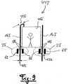
- FIG. 9 1 schematically shows an embodiment of an elevator installation 44I with two rails 161 as a stationary device of the elevator installation 44I, a car 46I and two embodiments of a ninth embodiment of a braking apparatus 2I for braking the car 46I, each with two brake modules 6I. It is here provided that a thickness 48I of one of the rails 16I is 16 mm and a depth 50I of one of the rails 16I is approximately 50 mm.
- braking devices 2I for braking are in the basis of FIG. 9 described embodiment, with the provision of each one L furnishspalts 181 with a width 521 of 4 mm between each brake module 6I and a rail 16I in the first operating position, which is achieved in that not shown here pawls with the brake modules 6I are connected.
- a release force transmitted from a pawl to a brake module 6I is changed.
- the brake modules 6I disengage from the pawls and reach a second operating position so that the brake modules 18I touch the rails 16I, thereby generating friction.
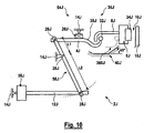
- FIG. 10 shows a schematic representation of a Tenth embodiment of a brake device 2J, which like the other embodiments already presented a pawl 4J, an electromagnet 20J, a brake module 6J with a brake pad 34J, a counterpart 8J, mounted on a wall 14J electromagnet 20J and a latching 40J includes.
- This embodiment of the brake device 2J is provided as a component of a vehicle designed as a car.
- the pawl 4J and the brake module 6J are in a first variant of a first operating position 36J, wherein between the brake pad 34J of the brake module 6J and a rail 16J, to which the car can move, a ventilation gap 18J is present.
- an arc 30J and a ball 32J of the pawl 4J are shown in phantom in a second position of the first operating position 360J offset to the right, which ensures that the pawl 4J changes when a release force is changed and thus Move brake module 6J in the direction of the rail 16J and thus causes a braking effect of the car.
- FIG. 10 a latching mechanism 54J designed as a ventilation unit, which has a linear motor 56J mounted on a wall 14J and a lever 12J and a lever arm 58J.
- the lever 12J is connected at a first end to the linear motor and connected at a second end via a pivot point 28J with the lever arm 58J.
- the lever arm 58J is mounted on a wall 14J via a second pivot point and rotatably connected to the pawl 4J via a third pivot point 28J.
- the brake device 2J with the ventilation unit or the latch mechanism 34J is basically in FIG. 10 shown.
- a translational movement of the linear motor 56J is transmitted to the brake module 6J via a lever transmission provided via the lever 12J, the lever arm 58J and the pawl 4J, for varying the release force and further a position of the brake module 6J via the pawl 4J.
- the pawl 4J In front of the brake module 6J, the pawl 4J is interposed, which is held by the electromagnet 20J in a horizontally oriented first operating position 36J. As a result, the pawl 4J engages with the counterpart 8J connected to the brake module 6J and can move the brake module upon movement of the linear motor 56J, thereby regulating the release force.
- the electromagnet 20J is de-energized, so that the pawl 4J falls to the level of Einklink Anlagen 40J, so that the linear motor 56J has no intervention on the brake module 6J.
- the brake module 6J can be opened and closed by a motor. Large air gaps 18J can also be realized by adjusting the release force and the geometry of the lever 58J. However, a collapse of the brake module 6J is also possible via the pawl 4J.
- the linear motor 56J retracts.
- the pawl 4J is pushed forward on the inclined plane of the Einklink Anlagen 40J and thereby lifted until it again has contact with the electromagnet 20J. If this is still de-energized, no engagement of the pawl 4J in the counterpart 8J is possible. However, when the electromagnet 20J is energized again, the pawl 4J is held by it in a horizontal position again. Airing is now possible again with the 56J linear motor.
- FIG. 11 shows a ventilation device of a schematically illustrated embodiment of a braking device 2K with a pawl 4K and a brake module 6K, which includes a brake pad 34K, a counterpart 8K and brake lever 60K and fixed points 62K.
- the schematic representation of FIG. 11 further shows an electromagnet 20K, which attracts the pawl 4K in an energized state and a portion of a lever arm 58K, via which a force of a motor not shown here can be transferred to the pawl 4K.
- a release force here a compressive force of the motor for releasing the brake module 6K is used.
- the motor or linear motor is connected to the upper hole 58K on the pawl 4K.
- the motor presses the pawl 4K on the counterpart 8K and then on the lever 60K of the brake module 6K.
- the levers 60K are fixedly mounted at their fixed points 62K. This creates a rotation about these fixed points 62K. Pressing the motor thereby causes the brake shoes 34K to move apart.
- the engine for airing bypasses. thus compensates for the contact force exerted by a spring, not shown, which acts on the brake shoes 34K in the region of a rail.
- the latch 4K itself presses on the counterpart 8K.
- the contacting surfaces of the pawls 4K and the counterpart 8K are inclined by a few degrees to an axis of the pawl 4K. This results in the released state at the latch 4K a release force down. This is compensated by the placed on the pawl 4K electromagnet 20K again. Triggering the pawl 4K is thus possible by switching off the voltage at the electromagnet 20K.
- the pressure force due to the airing and the weight of the pawl 4K itself always lead to a fall when the electromagnet 20K is de-energized. Due to the fail-safe function of the brake device 2K, the brake pads 34 of the brake module 6K are always pressed by the spring in case of supply energy failure.
- FIG. 12 shows a schematic representation of an example of a twelfth brake device 2L with a Pawl 4L, which is mounted on a wall 14L, an electromagnet 20L and a counterpart 8L of a brake module not shown here.
- braking device 2L If the in FIG. 12 shown braking device 2L is in the first operating position, it is provided that the solenoid 20L is energized and thus pulls the pawl 4L upwards. Furthermore, a variable release force 22L is applied from a drive of a mechanism of the pawl 4L, not shown here, whereby a connection between the pawl 4L and the counterpart 8L of the brake module is provided. Due to the release force 22L, a release force 64L is generated at the contact surface between the pawl 4L and the counterpart 8C, which is not vertical to the line of action of the release force 22L. This release force 64L is applied to energized electromagnet 20L.
- the pawl 4L detaches itself from the electromagnet 20L due to its mass and falls down, interrupting a connection of the pawl 4L to the counterpart 8L and thus also to the brake module.
- the weight of the pawl 4L an additional, typically small contribution to the release force 64L is contributed. This results in that the pawl 4L and the brake module occupy a second operating position, is canceled by a present during the first operating position air gap between a rail not shown here and the brake module, so that braking or catching a car, the here shown twelfth embodiment of the braking device 2L, is effected.
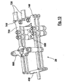
- FIG. 13 A holding device of a thirteenth embodiment of a brake device 2M is shown in FIG FIG. 13 shown schematically.
- This holding device comprises a latching aid 40M, a magnetic attachment 66M, a connection plate 68M, a spacer 70M and two Z-profiles 72M.
- This holding device FIG. 13 is provided as a frame for a ventilation device, the electromagnet and a jack, not shown, and an unillustrated counterpart of a brake module, which are described in the preceding figures, however, provided.
- the two Z-profiles 72M absorb the braking force from underlying brake shoes.
- the Z-profiles 72M are bolted to the two spacers 70M. These absorb the braking forces and forward them down to the connection plate 68M, which can be moved horizontally depending on the application.
- the spacer 70M absorbs the braking forces and forwards them. Holes 74M of the spacer 70M engage bolts that provide the fulcrums for lever control of the vent. The spacer 70M thus absorbs the spring force in the region of a guide rail in the released state. In the middle of FIG. 13 On the spacer 70M is seen the bracket 66M for the electromagnet, which holds the latch in balance. In the left area is the Einklink Anlagen 40M to see that returns the pawl by a movement of a motor of a latch mechanism again automatically in the starting position and thus a first operating position shown.
Abstract
Description
Die Erfindung betrifft eine Bremsvorrichtung zum Bremsen eines Fahrkorbs, eine Aufzuganlage sowie ein Verfahren zum Einstellen mindestens eines Bremsmoduls.The invention relates to a braking device for braking a car, an elevator system and a method for adjusting at least one brake module.
Zum Bremsen und Fangen eines Fahrkorbs einer Aufzuganlage sind verschiedene Mechanismen bekannt, die durch geeignete Bremsvorrichtungen realisiert werden können.For braking and catching a car of an elevator system, various mechanisms are known which can be realized by suitable braking devices.
UmfüreineBremsebspw.großeAnpresskräfte bereitzustellen und diese im sogenannten Fail-Safe-Modus und demnach im stör- oder ausfallsicheren Betrieb wieder freigeben zu können, werden, wie bspw. in der Druckschrift
Um größere Lüftspalte zu realisieren, können Federsysteme eingesetzt werden. Ein Beispiel hierzu sind Federspeicherbremsen mit Schraubfedern, wie sie im Fall der Druckschrift
Eine aus der Druckschrift
Eine Bremseinrichtung, mit der ein großer Lüftspalt realisiert werden kann, ist in der Druckschrift
Soll mit dem aktuellen Stand der Technik eine ausfallsichere Bremse realisiert werden, die den entsprechenden Lüftspalt aufweist, so müsste diese, um Notbremsfunktionen durchführen zu können, sehr schnell einfallen. Dies erzeugt jedoch einen sehr hohen Lärmpegel. Ein langsames und somit leises Anlegen im normalen Betriebszustand, wenn also kein Gefahrenfall vorliegt, ist hier nicht möglich.If a fail-safe brake is to be realized with the current state of the art, which has the corresponding air gap, then this would have to come to emergency braking functions to perform very quickly. However, this generates a very high noise level. A slow and thus quiet application in normal operating condition, so if there is no danger, is not possible here.
Sogenannte Fangvorrichtungen, mit denen ein augenblickliches Anhalten herbeigeführt werden kann, werden nach dem heutigen Stand der Technik durch sogenannte Keilbremsen realisiert. Hierbei wird, wie beispielsweise in der Druckschrift
Eine Alternative dieser Fangvorrichtung wird in der Druckschrift
Vor diesem Hintergrund werden eine Bremsvorrichtung, eine Aufzuganlage und ein Verfahren mit den Merkmalen derunabhängigen Patentansprüche vorgestellt.Against this background, a brake device, an elevator system and a method having the features of the independent claims are presented.
Die Erfindung betrifft eine Bremsvorrichtung zum Bremsen eines sich relativ zu einem Aufzugschacht bewegenden Fahrkorbs, mit mindestens einem Bremsmodul, das dazu vorgesehen ist, mit einer sich relariv zu dem Bremsmodul bewegenden Einrichtung zusammenzuwirken, und mit einer zwischen zwei Betriebsstellungen verstellbaren Klinke, wobei die Klinke in einer ersten Betriebsstellung mit dem mindestens einen Bremsmodul derart verbunden ist, dass von der Klinke auf das mindestens eine Bremsmodul eine Lüftkraft übertragen wird, und wobei die Klinke in einer zweiten Betriebsstellung von dem mindestens einen Bremsmodul getrennt ist, so dass sich das mindestens eine Bremsmodul mit der Einrichtung in Kontakt befindet.The invention relates to a braking device for braking a car moving relative to a hoistway, comprising at least one brake module intended to cooperate with a device moving relative to the brake module, and having a pawl adjustable between two operating positions, the pawl in a first operating position with the at least one brake module is connected such that from the pawl on the at least one brake module, a release force is transmitted, and wherein the pawl is separated in a second operating position of the at least one brake module, so that the at least one brake module with the device is in contact.
Diese Bremsvorrichtung ist zudem dazu ausgebildet, in der zweiten Betriebsstellung der Klinke eine Notbremsung als eine Ausgestaltung einer Bremsung zu realisieren, so dass die Bremsvorrichtung auch als eine sogenannte Fangvorrichtung bezeichnet werden kann. In der ersten Betriebsstellung ist vorgesehen, dass durch Regulierung der Lüftkraft eine Breite eines Lüftspalts zwischen dem mindestens einen Bremsmodul und der Einrichtung einstellbar ist, so dass eine Bremskraft in geeigneter Weise eingestellt werden kann. Demnach ist es auch möglich, in der ersten Betriebsstellung eine ungebremste Fahrt des Fahrkorbs zuzulassen.This braking device is also designed to realize an emergency braking in the second operating position of the pawl as an embodiment of a braking, so that the braking device can also be referred to as a so-called safety gear. In the first operating position is provided that by regulating the release force a width of a gap between the at least one brake module and the device is adjustable, so that a braking force can be adjusted in a suitable manner. Accordingly, it is also possible to allow in the first operating position an unrestricted ride of the car.
In Ausgestaltung ist die Einrichtung als stationäre Einrichtung, bspw. als Schiene einer Aufzuganlage ausgebildet. Eine Bewegung des Fahrkorbs kann mit der Bremsvorrichtung gebremst sowie abgefangen werden.In an embodiment, the device is designed as a stationary device, for example as a rail of an elevator system. A movement of the car can be braked with the braking device and intercepted.
In einer weiteren Ausgestaltung ist die Bremsvorrichtung relativ zu dem Aufzugschacht ortsfest angeordnet. In diesem Fall ist das Bremsmodul dazu ausgebildet, mit einer sich bewegenden Einrichtung zusammenzuwirken. Dabei ist die sich bewegende Einrichtung bspw. als ein Tragmittel, z.B. als ein Seil oder ein Satz von Seilen, ausgebildet. Über ein derartiges Tragmittel wird der Fahrkorb innerhalb des Aufzugschachts bewegt. Durch Zusammenwirken des Bremsmoduls mit dem Treibmittel kann eine Bewegung des Treibmittels und somit des Fahrkorbs in der ersten Betriebsstellung bedarfsweise gebremst werden. In der zweiten Betriebsstellung wird die Bewegung des Treibmittels und somit des Fahrkorbs notgebremst bzw. abgefangen.In a further embodiment, the braking device is arranged stationary relative to the elevator shaft. In this case, the brake module is configured to cooperate with a moving device. In this case, the moving device is, for example, as a suspension means, e.g. as a rope or a set of ropes. About such a suspension means of the car is moved within the elevator shaft. By cooperation of the brake module with the propellant, a movement of the propellant and thus of the car in the first operating position can be braked, if necessary. In the second operating position, the movement of the propellant and thus the car is braked or intercepted.
Die Bremsvorrichtung weist mindestens einen Antrieb zur Bereitstellung und Variation der Lüftkraft auf.The brake device has at least one drive for providing and varying the release force.
Zudem kann die Bremsvorrichtung eine bspw. als Elektromagnet ausgebildete Halteeinrichtung aufweisen, die dazu ausgebildet ist, die Klinke in der ersten Betriebsstellung zu halten. Der Elektromagnet hält die Klinke in einem bestromten Zustand in der ersten Betriebsstellung. Der Elektromagnet kann derart mit elektrischer Energie, die bspw. von der Aufzuganlage bereitgestellt wird, versorgt und somit bestromt werden, dass die Klinke bei einem Ausfall der Energieversorgung von dem Elektromagneten gelöst wird und somit ein Nothalt des Fahrkorbs herbeigeführt werden kann.In addition, the braking device may have, for example, a holding device designed as an electromagnet, which is designed to hold the pawl in the first operating position. The electromagnet holds the pawl in an energized state in the first operating position. The electromagnet can be supplied with electrical energy, which is provided, for example. By the elevator system, and thus energized, that the pawl is released in case of failure of the power supply from the solenoid and thus an emergency stop of the car can be brought about.
Außerdem kann die Bremsvorrichtung mindestens einen Hebel aufweisen, der dazu ausgebildet ist, einen Abstand zwischen dem Bremsmodul und der Einrichtung einzustellen.In addition, the brake device may comprise at least one lever which is adapted to set a distance between the brake module and the device.
In einer Variante kann vorgesehen sein, dass die Bremsvorrichtung mindestens ein, bspw. als Feder ausgebildetes, Kraftmodul und/oder einen Energiespeicher aufweist, das und/oder der dazu ausgebildet ist, für das mindestens eine Bremsmodul eine Bremskraft bereitzustellen. Dabei wirkt die Bremskraft der Lüftkraft vektoriell entgegen.In a variant, it can be provided that the braking device has at least one, for example. Designed as a spring, power module and / or energy storage, which is and / or is adapted to provide a braking force for the at least one brake module. The braking force of the release force vectorially counteracts.
Das mindestens eine Bremsmodul kann als eine Komponente ein Gegenstück aufweisen, das dazu ausgebildet ist, mit der Klinke zusammenzuwirken, wobei die Klinke mit dem Gegenstück in derersten Betriebsstellung in Eingriff steht.The at least one brake module may include as a component a counterpart adapted to cooperate with the pawl, the pawl being engaged with the counterpart in the first operative position.
In weiterer Ausgestaltung kann die Bremsvorrichtung mindestens eine Einklinkhilfe aufweisen, die dazu ausgebildet ist, die Klinke bspw. selbsttätig und/oder elektromechanisch von der zweiten Betriebsstellung in die erste Betriebsstellung zu überführen.In a further embodiment, the braking device can have at least one latching aid, which is designed to transfer the latch, for example, automatically and / or electromechanically from the second operating position into the first operating position.
Die erfindungsgemäße Aufzuganlage weist mindestens eine voranstehend beschriebene Bremsvorrichtung sowie mindestens einen Fahrkorb auf.The elevator installation according to the invention has at least one braking device described above and at least one car.
Die Erfindung betrifft zudem ein Verfahren zum Einstellen mindestens eines Bremsmoduls für einen sich relativ zu einem Aufzugschacht bewegenden Fahrkorb, wobei das mindestens eine Bremsmodul dazu vorgesehen ist, mit einer Einrichtung zusammenzuwirken. Bei diesem Verfahren wird eine Klinke zwischen zwei Betriebsstellungen hin- und hergeschaltet, wobei die Klinke in einer ersten Betriebsstellung mit dem mindestens einen Bremsmodul derart verbunden ist, dass von der Klinke auf das mindestens eine Bremsmodul eine Lüftkraft übertragen wird, und wobei das mindestens eine Bremsmodul und die Klinke bei einem Umschalten in die zweite Betriebsstellung voneinander getrennt werden, so dass das mindestens eine Bremsmodul mit der Einrichtung in Kontakt gerät.The invention also relates to a method for adjusting at least one brake module for a car moving relative to a hoistway, wherein the at least one brake module is intended to cooperate with a device. In this method, a pawl is switched back and forth between two operating positions, wherein the pawl is connected in a first operating position with the at least one brake module such that a release force is transmitted from the pawl to the at least one brake module, and wherein the at least one brake module and the pawl are separated from each other when switching to the second operating position, so that the at least one brake module is in contact with the device.
Mit dem Verfahren ist es für den Fall, dass sich die Klinke in der ersten Betriebsstellung befindet, möglich, dass durch Änderung der Lüftkraft eine Breite eines Lüftspalts zwischen der Einrichtung und dem mindestens einen Bremsmodul reguliert wird, so dass der Fahrkorb gebremst wird. Eine Änderung der Lüftkraft bewirkt ein Anlegen der Bremsbeläge an der Einrichtung. Durch weiteres Reduzieren der Bremskraft kann hierbei eine definierte Bremskraft bereitgestellt werden.With the method, in the event that the pawl is in the first operating position, it is possible that a width of a clearance between the device and the at least one brake module is regulated by changing the release force, so that the car is braked. A change in the release force causes application of the brake pads on the device. By further reducing the braking force in this case a defined braking force can be provided.
Für den Fall, dass sich die Klinke in der zweiten Betriebsstellung befindet, ist es möglich, dass das mindestens eine Bremsmodul mit der Einrichtung derart in Kontakt gerät, dass der Fahrkorb gestoppt bzw. notgebremst wird.In the event that the pawl is in the second operating position, it is possible that the at least one brake module is in contact with the device such that the car is stopped or emergency braked.
Zumindest ein Schritt des erfindungsgemäßen Verfahrens ist durch die erfindungsgemäße Bremsvorrichtung oder durch mindestens eine Komponente dieser Bremsvorrichtung durchführbar. Eine Funktion mindestens einer Komponente der Bremsvorrichtung oder der Bremsvorrichtung selbst kann als ein Schritt des vorgestellten Verfahrens realisiert werden.At least one step of the method according to the invention can be carried out by the braking device according to the invention or by at least one component of this braking device. A function of at least one component of the braking device or the braking device itself can be realized as a step of the presented method.
Typischerweise umfasst die Bremsvorrichtung mindestens ein Bremsmodul, das mit mindestens einer Einrichtung und üblicherweise mit mindestens einer Klinke zusammenwirken kann.Typically, the brake device comprises at least one brake module that can interact with at least one device and usually with at least one pawl.
Mit der Bremsvorrichtung ist bspw. eine Sicherheitsbremse realisierbar, bei der ein Einfallen der Bremse durch einen Klinkenmechanismus, der die Klinke umfassen kann, ausgelöst werden kann.With the brake device, for example, a safety brake can be realized, in which a collapse of the brake by a latch mechanism, which may include the pawl, can be triggered.
Bei einer Variante der Bremsvorrichtung ist vorgesehen, dass die Klinke von einem Antriebsmodul bzw. einem Antrieb als eine Komponente eines Klinkenmechanismus bewegt wird, wodurch das mindestens eine Bremsmodul auf- und zugefahren werden kann, wobei ein derartiger Antrieb auch als ein Lüftantrieb der Bremsvorrichtung ausgebildet sein kann.In a variant of the braking device is provided that the pawl is moved by a drive module or a drive as a component of a latch mechanism, whereby the at least one brake module can be opened and closed, wherein such a drive may also be designed as a Lüftantrieb the braking device can.
Eine Lüftkraft der Bremsvorrichtung, wobei diese Lüftkraft u.a. durch ein Zusammenwirken der Klinke und des Elektromagneten derart bereitgestellt wird, dass das Bremsmodul unter Bereitstellung des Lüftspalts von der Einrichtung beabstandet ist, kann durch die Klinke unterbrochen werden. Demnach ist die Klinke als Übertragungsmittel zur Bereitstellung einer Wechselwirkung zwischen dem Antriebsmodul und dem Bremsmodul ausgebildet.A release force of the brake device, wherein this release force is provided, inter alia, by an interaction of the pawl and the electromagnet such that the brake module is spaced from the device to provide the air gap, can by the pawl to be interrupted. Accordingly, the pawl is designed as a transmission means for providing an interaction between the drive module and the brake module.
Der mindestens eine Klinkenmechanismus kann bspw. auch einen Energiespeicher aufweisen, der dazu geeignet ist, eine Kraft aufzubringen, durch die die Klinke an dem Bremsmodul eingehängt werden kann, so dass sich die Klinke nach einem derartigen Einhängen ausgehend von der zweiten Betriebsstellung wieder in der ersten Betriebsstellung befindet und zwischen dem Bremsmodul und der Einrichtung der Lüftspalt bereitgestellt wird.The at least one latch mechanism may, for example, also have an energy store which is suitable for applying a force by means of which the pawl can be hooked onto the brake module, so that the pawl, after such a hooking up, starts again from the second operating position in the first Operating position and is provided between the brake module and the device of the air gap.
In einer Lüfteinheit als weitere optionale Komponente des Klinkenmechanismus der Bremsvorrichtung kann ein zusätzliches Getriebe angeordnet sein. Des weiteren kann der Klinkenmechanismus eine selbstständige und/oder selbsttätige Einklinkhilfe bzw. Einklinkeinheit aufweisen.In an airing unit as a further optional component of the pawl mechanism of the brake device, an additional gear can be arranged. Furthermore, the latch mechanism can have an independent and / or automatic latching aid or latching unit.
Bei Betrieb der Bremsvorrichtung ist vorgesehen, dass bei Abschalten des Elektromagneten, d.h. Unterbrechung der Bestromung des Elektromagneten, die Klinke einfällt und sich somit von dem Bremsmodul trennt. Solang der Elektromagnet bestromt wird oder ist, wird die Klinke in der ersten Betriebsstellung gehalten. In dem Augenblick, an dem der Elektromagnet nicht mehr bestromt wird, kann der Elektromagnet die Klinke nicht mehr magnetisch anziehen, so dass sich die Klinke von dem Elektromagneten löst und somit gleichzeitig von dem Bremsmodul trennt.During operation of the brake device, it is provided that when the electromagnet is switched off, i. Interruption of the energization of the electromagnet, the pawl is incident and thus separates from the brake module. As long as the electromagnet is energized or is, the pawl is held in the first operating position. At the moment when the electromagnet is no longer energized, the solenoid can no longer magnetically attract the pawl, so that the pawl releases from the electromagnet and thus simultaneously separates from the brake module.
Der im Rahmen der Erfindung unter anderem vorgesehene Klinkenmechanismus zur geeigneten Positionierung der Klinke in einer jeweiligen Betriebsstellung kann derart ausgebildet sein, dass durch die Bremsvorrichtung in herkömmlicher Weise durchzuführende Bremsvorgänge nicht beeinflusst werden.The inter alia provided in the context of the invention pawl mechanism for the appropriate positioning of the pawl in a respective operating position may be formed such that braking operations to be performed by the braking device in a conventional manner are not affected.
Des weiteren kann die Bremsvorrichtung einen selbsthemmenden Antrieb und/oder ein selbsthemmendes Getriebe als mögliche Komponente des Klinkenmechanismus aufweisen.Furthermore, the braking device may have a self-locking drive and / or a self-locking gear as a possible component of the latch mechanism.
DerKlinkenmechanismusweisttypischerweise keine selbsthemmenden Elemente zur Bremsung auf. In der ersten Betriebsstellung kann die Klinke u.a. durch ein selbsthemmendes Getriebe und einen Antrieb ergänzt werden.The latching mechanism typically does not have self-locking elements for braking. In the first operating position, the latch u.a. be supplemented by a self-locking gear and a drive.
Ein Lüften der Bremsvorrichtung und insbesondere des Bremsmoduls der Bremsvorrichtung, das in der Regel immer dann erfolgt, wenn sich die Klinke in der ersten Betriebsstellung befindet, kann in Ausgestaltung auch als ein sogenanntes symmetrisches Lüften vorgesehen sein, das auch bei motorischem Lüften möglich ist. Ein beschriebenes symmetrisches Lüften kann durch eine Ansteuerung mindestens eines Hebels als Komponente des Klinkenmechanismus realisiert werden, wobei ein derartiger Hebel in mindestens einem Fixpunkt eingesetzt ist. Durch geeignete Positionierung des mindestens einen Fixpunkts sowie Dimensionierung des mindestens einen Hebels ist eine Übersetzung der zum Lüften vorgesehenen Lüftkraft möglich. Dabei kann ein Lüftweg durch eine Exzentrität des mindestens einen Hebels realisiert werden. Der beschriebene Klinkenmechanismus oder ein entsprechendes Gerät zum Lüften kann des weiteren zum Lüften weiterer Bremsmodule eingesetzt werden.Airing the brake device and in particular of the brake module of the brake device, which usually takes place when the pawl is in the first operating position, may be provided in a design as a so-called symmetrical ventilation, which is also possible with motorized ventilation. A described symmetrical lifting can be realized by controlling at least one lever as a component of the latch mechanism, wherein such a lever is inserted in at least one fixed point. By suitable positioning of the at least one fixed point as well as dimensioning of the at least one lever, a translation of the venting force provided for ventilation is possible. In this case, a Lüftweg be realized by an eccentricity of the at least one lever. The latch mechanism described or a corresponding device for ventilation can also be used to ventilate additional brake modules.
Die Bremsvorrichtung kann derart ausgelegt werden, dass ein Übergang der Klinke von der ersten Betriebsstellung in die zweite Betriebsstellung in einem kurzen Zeitraum und somit ruckartig erfolgt. Bei Einsatz eines geeignet dimensionierten Energiespeichers, insbesondere einer Feder, die zum Beaufschlagen des Bremsmoduls ausgebildet ist, kann der Lüftspalt zwischen dem Bremsmodul und der Einrichtung über eine hinreichend große Anpresskraft sofort geschlossen werden, so dass mit der Bremsvorrichtung u.a. eine Notbremsung durchgeführt werden kann, so dass die Bremsvorrichtung unter diesem Aspekt auch als eine Fangvorrichtung bezeichnet werden kann. Eine derartige Fangvorrichtung wird ebenfalls durch Änderung der Betriebsstellung der Klinke und einer daraus folgenden Änderung einer Position oder Stellung des Bremsmoduls relativ zu der Einrichtung ausgelöst und somit aktiviert.The brake device can be designed such that a transition of the pawl from the first operating position to the second operating position takes place in a short period of time and thus jerkily. When using a suitably dimensioned energy store, in particular a spring which is designed to act on the brake module, the air gap between the brake module and the device can be closed immediately via a sufficiently large contact force, so that u.a. An emergency braking can be performed, so that the braking device can be referred to in this aspect as a safety gear. Such a safety gear is also triggered by changing the operating position of the pawl and a consequent change in position or position of the brake module relative to the device and thus activated.
Ein Notbremsen und somit ein Fangen des sich bewegenden Fahrkorbs relativ zu dem Aufzugschacht kann in mehreren Fahrtrichtungen erfolgen. So ist es für den Fall, dass die insbesondere stationäre Einrichtung als Schiene einer Aufzuganlage ausgebildet ist, möglich, dass durch die Bremsvorrichtung sowohl eine Aufwärtsals auch eine Abwärtsbewegung des Fahrkorbs schnell und sicher gestoppt werden kann.An emergency braking and thus catching the moving car relative to the elevator shaft can be done in several directions. Thus, in the case that the particular stationary device is formed as a rail of an elevator system, it is possible that both an upward and a downward movement of the car can be stopped quickly and safely by the braking device.
Falls die Einrichtung als sich bewegende Einrichtung, bspw. als Tragmittel, ausgebildet ist, kann eine Abwärtsbewegung des Fahrkorbs effektiv gebremst oder gestoppt werden, wenn das Bremsmodul insbesondere mit einem sich abwärts bewegenden Strang des Tragmittels zusammenwirkt. Eine Aufwärtsbewegung des Fahrkorbs wird dadurch effektiv gebremst oder gestoppt, indem das Bremsmodul insbesondere mit einem sich aufwärts bewegenden Strang des Tragmittels zusammenwirkt. In der Regel kann ein Bremsen oder Stoppen einer Bewegung des Fahrkorbs richtungsunabhängig durch Zusammenwirken eines beliebigen Abschnitts bzw. Strangs des Tragmittels mit dem Bremsmodul erfolgen.If the device is designed as a moving device, for example as a suspension element, a downward movement of the car can be effectively braked or stopped when the brake module interacts in particular with a downwardly moving strand of the suspension element. An upward movement of the car is thereby effectively braked or stopped by the brake module interacts in particular with an upwardly moving strand of the support means. In general, a braking or stopping a movement of the car can be independent of direction by interaction of any section or strand of the suspension element with the brake module.
In einer weiteren Variante kann die Bremsvorrichtung, insbesondere wenn sie zum Fangen des Fahrkorbs ausgebildet ist, ein als Fangkeil ausgebildetes Bremsmodul aufweisen, wobei ein derartiger Fangkeil mit einer Einheit zum Einziehen zusammenwirkt, die wiederum durch die Klinke beim Übergang in die zweite Betriebsstellung ausgelöst werden kann, so dass über den Fangkeil die Notbremsung herbeigeführt werden kann. Die Erzeugung der Bremskraft kann dann durch eine Keilwirkung des Fangkeils erfolgen.In a further variant, the braking device, in particular if it is designed to catch the car, have a trained as a catch wedge brake module, wherein such a catch wedge cooperates with a unit for retraction, which in turn can be triggered by the pawl in the transition to the second operating position , so that the emergency stop can be brought about the catch wedge. The generation of the braking force can then take place by a wedging action of the catching wedge.
Durch die Erfindung kann u.a. eine Bremsvorrichtung mit großem Lüftspalt zum Bremsen und/oder Fangen eines Fahrkorbs realisiert werden. Diese Bremsvorrichtung fällt aufgrund der Druckfeder zum Beaufschlagen des Bremsmoduls und des Einsatzes des Elektromagneten zum Halten der Klinke bei Ausfall der Versorgungsenergie selbstständig komplett ein. Sie ist somit in allen Betriebssituationen sicher (fail-safe).By the invention, inter alia, a brake device with a large air gap for braking and / or catching a car can be realized. This brake device falls completely due to the compression spring for applying the brake module and the use of the electromagnet for holding the pawl in case of failure of the supply energy completely. It is thus safe in all operating situations (fail-safe).
Durch eine Hebelansteuerung als Komponente des Klinkenmechanismus kann eine Übersetzung zwischen einem Lüftmotor als Antrieb des Klinkenmechanismus und an der Lüftkraft, die auf das durch die Feder beaufschlagte Bremsmodul wirkt, eingestellt werden. Die Hebelansteuerung ermöglicht u.a. ein symmetrisches Lüften. Dadurch kann der Fahrkorb, eine Aufzugkabine oder ein entsprechendes Fahrzeug ohne Schleifgeräusche von Bremsbelägen des mindestens einen Bremsmoduls anfahren, ohne dass die Bremsvorrichtung zum Bremsen komplett gelüftet ist, da sich die Bremsbeläge gleichzeitig von der Einrichtung abheben und somit von dieser entfernen.By a lever control as a component of the pawl mechanism, a translation between a Lüftmotor as a drive of the latch mechanism and on the release force, which acts on the acted upon by the spring brake module can be adjusted. The lever control allows u.a. a symmetrical airing. As a result, the car, an elevator car or a corresponding vehicle without grinding noises of brake pads of at least one brake module start without the brake device is fully released for braking, as the brake pads simultaneously stand out from the device and thus remove it.
Durch den Klinkenmechanismus oder zumindest eine Komponente des Klinkenmechanismus, bspw. den Antrieb bzw. Lüftmotor, kann die Bremsvorrichtung zum Bremsen motorisch auf- und zugefahren werden. Dabei ist üblicherweise vorgesehen, dass die Lüftkraft, die über eine geeignete Bewegung des Antriebs erzeugt wird, von dem Antrieb über die Klinke als Mittel zur Übertragung der Lüftkraft zu dem Bremsmodul übertragen wird.By means of the latching mechanism or at least one component of the latching mechanism, for example the drive or venting motor, the braking device can be opened and closed by a motor for braking. It is usually provided that the release force, which is generated via a suitable movement of the drive is transmitted from the drive via the pawl as a means for transmitting the release force to the brake module.
Durch die Möglichkeit, Bremsmodule, die Bremsbacken oder Bremsbeläge aufweisen können, motorisch an die Einrichtung, bspw. Schiene, anzulegen, kann eine Auftreffgeschwindigkeit der Bremsbeläge auf die Schiene gesteuert werden. Dadurch können des weiteren eine Einfallgeschwindigkeit und der Geräuschpegel beim Einfallen der Klinke und somit des Bremsmoduls reguliert werden.Due to the possibility of having brake modules, which may have brake shoes or brake pads, motorized to the device, for example. Rail, create an impact velocity of the brake pads can be controlled on the rail. As a result, further, an incident speed and the noise level at the time of engagement of the pawl and thus the brake module can be regulated.
Durch einen entsprechend ausgebildeten Antrieb des Klinkmechanismus bzw. eines Lüftgeräts kann des weiteren auch die über eine Fail-Safe-Funktion aufgebrachte Anpresskraft kontrolliert und somit gesteuert und/oder geregelt werden. Ein motorisches Anlegen des Lüftgeräts kann auch kurz vor Einleitung einer Bremsung erfolgen, wodurch die Einfallzeit der Bremse bzw. eines Bremsmoduls verkürzt wird. Dies kann motorisch oder durch die Klinke erfolgen.By an appropriately trained drive of the latching mechanism or a Lüftgeräts also applied via a fail-safe function contact pressure can be controlled and thus controlled and / or regulated. A motorized application of the Lüftgeräts can also be done shortly before the initiation of braking, whereby the Einfallzeit the brake or a brake module is shortened. This can be done by motor or by the pawl.
Durch den Elektromagnet als Notauslösung für die Klinke können auch nicht sichere Antriebe zum Lüften der Bremse eingesetzt werden.By the electromagnet as emergency release for the pawl and non-safe drives for releasing the brake can be used.
Im Vergleich zu nicht selbsthemmenden Systemen, wie beispielsweise einem Spindeltrieb, ist die Einfallzeit durch den Klinkenmechanismus wesentlich geringer. Dadurch ergibt sich, dass ein freies Fallen des Fahrkorbs bei Energieausfall nicht bzw. nur sehr kurz stattfinden kann. Bei einer Bremse ohne selbstständige Rückstellung der Klinke erfüllt die beschriebene Bremsvorrichtung die grundlegenden Anforderungen für Fangvorrichtungen für Aufzüge nach EN 81. Aufgrund einer Auslösung durch den Elektromagneten sind sehr kleine Einfallzeiten möglich. Das Einfallen der Bremsvorrichtung kann zusätzlich durch einen Motor, der die Klinke beaufschlägt, mit mehreren Geschwindigkeitsstufen reguliert werden.Compared to non-self-locking systems, such as a spindle drive, the incidence time is much lower by the latch mechanism. This results in that a free fall of the car in case of power failure can not take place or only very briefly. In a brake without independent provision of the pawl brake device described meets the essential requirements for safety gear for lifts to EN 81. Due to a release by the electromagnet very small incidence times are possible. The collapse of the brake device can be additionally regulated by a motor which acts on the pawl, with several speed levels.
Anwendungsgebiete für die Bremsvorrichtung finden sich im Aufzugsbau als sogenannte Schienenbremse. Hier hat der Fahrkorbzu seinen Führungsschienen in der Regel ein erhebliches Spiel. Die Aufzugsrichtlinie und die EN 81 fordern allerdings ein sogenanntes Fail-Safe, d.h. ausfall- oder betriebssichere Bremssysteme, um einen Absturz des Fahrkorbs oder der Fahrkabine mit sehr hoher Sicherheitzu vermeiden. Somit muss ein Bremssystem eingesetzt werden, das große Lüftspalte und den Fail-Safe-Sicherheitsaspekt vereint.Application areas for the braking device can be found in elevator construction as a so-called rail brake. Here is the car to his guide rails usually a significant game. However, the Lifts Directive and EN 81 require a so-called fail-safe, i. failsafe or fail-safe braking systems to prevent crash of the car or cab with very high safety. Thus, a braking system must be used, which combines large gaps and the fail-safe safety aspect.
Die Bremsvorrichtung kann bspw. als Schienenbremse realisiert werden; hierbei ergibt sich, dass die Bremskraft nicht im Triebwerksraum, sondern am Fahrkorb erzeugt wird, also unmittelbar dort, wo sie benötigt wird.The braking device can be realized, for example, as a rail brake; this results in that the braking force is not generated in the engine room, but on the car, ie directly where it is needed.
Die Bremsvorrichtung kann durch den Klinkenmechanismus auch als Fangvorrichtung in Aufzügen eingesetzt werden. Des weiteren ist auch eine Kombination von Bremsvorrichtung und Fangvorrichtung in der Bremsvorrichtung möglich. Dadurch ergibt sich bspw., dass beim Einfallen beider Systeme, d.h. der Brems- und der Fangvorrichtung, keine extrem hohen Verzögerungen auf Fahrgäste im Fahrkorb wirken.The brake device can be used by the latch mechanism as a safety gear in lifts. Furthermore, a combination of brake device and safety gear in the brake device is possible. This results, for example., That when both systems, i. the brake and the safety gear, do not affect extremely high delays on passengers in the car.
Somit kann mit der Bremsvorrichtung u.a. eine Aufzugsfangvorrichtung mit Auslöseeinheiten realisiert werden, die Fliehkräfte aufweisen, um eine Übergeschwindigkeit des Fahrkorbs zu erkennen. Diese Auslöseeinheiten können sich mit ihren Fliehgewichten einhängen und somit die Fangvorrichtung durch Bewegen der Klinke von der ersten in die zweite Betriebsstellung auslösen.Thus, with the braking device u.a. a lift catcher can be realized with trip units having centrifugal forces to detect an overspeed of the car. These trip units can hang with their flyweights and thus trigger the safety gear by moving the pawl from the first to the second operating position.
Ein weiterer Einsatz der Bremse ist im Baumaschinen-, im Untertage- und im kompletten schienengebundenen Fördermittelbereich möglich. Durch den großen Lüftspalt ist die Bremse in Umgebungen mit starker Verschmutzung einsetzbar. Das im Rahmen der Erfindung bereitgestellte Fail-Safe-System erhöht auch hier die Zuverlässigkeit und Sicherheit der beschriebenen Anordnung.Further use of the brake is possible in the field of construction machinery, in the underground and in the complete rail-bound conveying area. Due to the large air gap, the brake can be used in environments with heavy pollution. The fail-safe system provided in the context of the invention here also increases the reliability and safety of the arrangement described.
Die Erfindung betrifft demnach u.a. eine Bremsvorrichtung zum Bremsen bzw. zur Verzögerung und/ oder zur Fixierung von Bewegungen von Fahrkörben. Das Abbremsen von schienengebundenen Fördermitteln, insbesondere Aufzügen, erfolgt hierbei durch Reibung an einer ortsfesten, parallel zur Förderrichtung verlaufenden Schiene als stationärer Einrichtung. Alternativ zu der Schiene ist dieselbe Anwendung auch zum Abbremsen von rotatorischen Bewegungen an einer Bremsscheibe als Einrichtung möglich. Die Reibbeläge des Bremsmoduls werden annähernd senkrecht zum Verlauf der Schiene von einer Freigabestellung und somitderersten Betriebsstellung in eine Bremsstellung und somit der zweiten Betriebsstellung bewegt. Damit wird ein Bremsvorgang eingeleitet. Eine Variante der Bremsvorrichtung weist einen Bremsbelag als Bremsmodul auf.The invention therefore relates inter alia to a braking device for braking or for deceleration and / or for fixing movements of cars. The braking of rail-bound conveying means, in particular elevators, in this case takes place by friction on a stationary rail running parallel to the conveying direction as a stationary device. As an alternative to the rail, the same application is also possible for braking rotational movements on a brake disk as a device. The friction linings of the brake module are moved approximately perpendicular to the path of the rail from a release position and thus the first operating position into a braking position and thus the second operating position. This initiates a braking process. A variant of the brake device has a brake pad as a brake module.
Nach einer weiteren Ausführungsart wird die Bremskraft über einen Keil erzeugt oder verstärkt. Dieser Keil kann über seine Gegenfläche bewegt und somit unter einem Winkel kleiner 90° zu der Schiene und demnach nicht senkrecht zum Schienenverlauf angelegt werden.According to another embodiment, the braking force is generated or amplified via a wedge. This wedge can be moved over its counter surface and thus at an angle less than 90 ° to the rail and therefore not perpendicular to the rail track applied.
Durch einen oder mehrere Energiespeicher, wie beispielsweise Druckfedern, wird die zur Reibung erforderliche Anpresskraft des Bremsmoduls gegen die Einrichtung erzeugt. Somit ist gegeben, dass bei einem Ausfall der Versorgungsenergie die volle Bremskraft bereitgestellt wird.By one or more energy storage, such as compression springs, the force required for friction contact pressure of the brake module is generated against the device. Thus, it is given that in case of failure of the supply energy, the full braking force is provided.
Die Bewegung von der Bremsstellung in die Freigabestellung erfolgt unter Energieaufnahme der Bremsvorrichtung bzw. eines entsprechenden Gesamtsystems. Ein Fluss der Federkraft wird hierbei im Bereich mindestens von einem bspw. als Bremsbacke ausgebildeten Bremsmodul umgeleitet. Das Überbrücken der Federkraft erfolgt mit Hilfe der Hebelansteuerung.The movement from the braking position into the release position takes place with energy absorption of the braking device or of a corresponding overall system. A flow of the spring force is in this case diverted in the region of at least one, for example, designed as a brake shoe brake module. The spring force is bridged by means of the lever control.
Eine Ausführungsart der Bremsvorrichtung sieht eine Anordnung eines Hebels ohne Fixpunkt vor. In diesem Falle wird der Lüftweg und somit Lüftspalt durch eine Exzentrität des Hebels erzeugt. Ein Kraftangriffspunkt kann demnach außerhalb einer Ebene der Einrichtung und somit bspw. der Schiene liegen. Dies erspart bspw. beim Einsatz von zwei Hebeln das Vorsehen eines Zwischenstücks.An embodiment of the braking device provides an arrangement of a lever without a fixed point. In this case, the Lüftweg and thus air gap is generated by an eccentricity of the lever. A force application point can therefore lie outside a plane of the device and thus, for example, the rail. This saves, for example, when using two levers, the provision of an intermediate piece.
Durch variierende Anordnung eines Drehpunkts am Hebel kann ein Übersetzungsverhältnis von erzeugter zu benötigter Lüftkraft bereitgestellt werden. Die Krafterzeugung zum Lüften des Bremsmoduls kann von einem Elektromotor, hydraulisch, pneumatisch oder durch sonstige Energiewandler erzeugt werden. Eine Übersetzung durch ein Getriebe ist möglich. Ein Antrieb kann auch zum Lüften mehrerer Bremsmodule zum Bremsen und/oder Fangen eingesetzt werden. Selbsthemmende Bauteile sind in diesem Bereich zur Einsparung der Versorgungsenergie einsetzbar, ohne dass dadurch die Sicherheitsfunktion der Bremsvorrichtung und demnach auch des Bremsmoduls beeinflusst wird. Am Ende dieser Antriebs- und Getriebeeinheit entsteht typischerweise eine Linearbewegung, die auf die Klinke übertragen wird.By varying the arrangement of a pivot point on the lever, a transmission ratio of generated to required release force can be provided. The power generation for releasing the brake module can be generated by an electric motor, hydraulically, pneumatically or by other energy converters. A translation through a gear is possible. A drive can also be used to ventilate multiple brake modules for braking and / or catching. Self-locking components can be used in this area to save energy supply, without affecting the safety function of the brake device and therefore also of the brake module. At the end of this drive and gear unit typically creates a linear motion, which is transmitted to the pawl.
Um die Bremsvorrichtung einfallen zu lassen, gibt es zwei Möglichkeiten den gelüfteten Zustand zu beenden. Dies kann durch Abfallen der Lüftkraft und somit Verschieben der Klinke erfolgen, oder dadurch, indem der Kraftfluss beispielsweise dadurch unterbrochen wird, dass die Klinke ausgehängt bzw. abgeklappt wird.In order to come up with the braking device, there are two ways to end the released state. This can be done by dropping the release force and thus moving the pawl, or thereby, by the power flow is interrupted, for example, characterized in that the pawl is posted or folded down.
Jeder dieser beiden Zustände bzw. dieser beiden Betriebsstellungen kann durch entsprechende Informationsgeber sicher erfasst und von einer Steuerung als weitere Komponente der Bremsvorrichtung verarbeitet werden. Dies kann beispielsweise durch Schalter in den Endlagen, Messelementen oder durch Schrittmotoren realisiert werden.Each of these two states or these two operating positions can be reliably detected by appropriate information sources and processed by a controller as another component of the braking device. This can be realized for example by switches in the end positions, measuring elements or by stepper motors.
Das Abfallen der Lüftkraft kann bei nicht-hemmenden Systemen dadurch realisiert werden, dass die Erzeugung der Lüftkraft unterbrochen wird. Eine erste Variante besteht darin, die vom Antrieb erzeugte Lüftkraft in ihrer Wirkrichtung umzukehren, was auch für selbsthemmende Systeme möglich ist. Die zweite Variante beruht auf einer Unterbrechung des Kraftflusses durch die Klinke, indem diese abgeklappt wird. Hierzu wird der Elektromagnet, der die Klinke in seiner Position hält, stromlos geschaltet.The drop in the release force can be realized in non-inhibiting systems that the generation of the release force is interrupted. A first variant is to reverse the release force generated by the drive in their effective direction, which is also possible for self-locking systems. The second variant is based on an interruption of the power flow through the latch by this is folded down. For this purpose, the electromagnet, which holds the pawl in its position, de-energized.
Durch die Gewichtskraft der Klinke, eine entsprechend gestaltete Formpaarung zwischen Klinke und Gegenstück des Bremsmoduls oder durch Energie aus zuvor verspannten Elementen, wie beispielsweise Federn oder anderen Energiespeichern oder Energiewandlern, wird die Klinke aus ihrer Lage gebracht. Eine Kombination dieser Möglichkeiten ist ebenfalls möglich.By the weight of the pawl, a correspondingly shaped shape pairing between the pawl and counterpart of the brake module or by energy from previously strained elements, such as springs or other energy storage or energy converters, the pawl is brought out of position. A combination of these possibilities is also possible.
Die Bremsvorrichtung zum Bremsen und/oder Fangen eines Fahrkorbs ist in einer Ausführung für ein Kabinengesamtgewicht von max. 1330 kg bei einer seillosen Aufzuganlage ausgelegt. Dabei ist die Bremsvorrichtung bzw. das Bremssystem vom Triebwerksraum direkt an den Fahrkorb bzw. die Kabine verlagert. Folgende Rahmenbedingungen können bspw. erfüllt werden:
- Abbremsen von max. 1330 kg
- Verzögerung bei voll beladenem Fahrkorb und Ausfall eines Bremsgeräts, bei einer Beschleunigung von a = -0,3 g.
- Maximale Verzögerung für den Fahrgast: 1 g
- Lüftspalt der Bremse 4 mm
Lebensdauer 9 000 000 LW (Lastwechsel)
- Braking of max. 1330 kg
- Delay with fully loaded car and failure of a braking device, with an acceleration of a = -0.3 g.
- Maximum delay for the passenger: 1 g
- Air gap of the brake 4 mm
-
Lifetime 9 000 000 LW (load change)
Des weiteren können zwei Bremsmodule zum Einsatz kommen, so dass eine Sicherheits-Schienenbremse mit einer Schienentiefe von ca. 50 mm und einer Schienendicke von ca. 16 mm realisiert wird.Furthermore, two brake modules can be used, so that a safety rail brake with a rail depth of about 50 mm and a rail thickness of about 16 mm is realized.
Mit der Lüfteinrichtung der Bremsvorrichtung können zwei Bremsmodule symmetrisch gelüftet werden. D.h. beide Bremsbacken bewegen sich gleichzeitig von der Schiene weg. Dadurch kann der Fahrkorb auch bei noch nicht komplett gelüfteter Bremse bereits ohne Schleifgeräusche anfahren. Auch ein Verringern des Lüftspalts kurz vor Erreichen einer Haltestelle ist dadurch möglich. Dadurch können Geschwindigkeitsverluste durch die Übersetzung der Hebel kompensiert werden. Auch der Einsatz von leichteren, langsameren Motoren als Antriebe für Klinkenmechanismen ist dadurch möglich.With the ventilation device of the brake device, two brake modules can be ventilated symmetrically. That Both brake shoes move away from the rail at the same time. As a result, even when the brake is not fully released, the car can already start without any grinding noises. It is also possible to reduce the clearance gap shortly before reaching a stop. As a result, speed losses can be compensated by the translation of the lever. The use of lighter, slower motors as drives for pawl mechanisms is thereby possible.
Wenn geringere Anlegegeschwindigkeiten realisiert werden können, nimmt auch der Geräuschpegel beim Einfallen der Bremse deutlich ab, was eine Erhöhung des Komforts für die Fahrgäste darstellt.If lower landing speeds can be realized, the noise level at the time of the brake decreases significantly, which is an increase in comfort for the passengers.
Mit der Bremsvorrichtung zum Bremsen können aufgrund des Aufbaus mit motorischer Betätigung und Klinkenauslösung mehrere Auslösegeschwindigkeiten realisiert werden. Durch den Einsatz des Elektromagneten ist die Bremsvorrichtung zum Bremsen als Fangvorrichtung für Übergeschwindigkeit nach unten und nach oben für herkömmliche Seilaufzüge gleichermaßen geeignet.With the braking device for braking a plurality of tripping speeds can be realized due to the structure with motor operation and latch release. Through the use of the electromagnet, the braking device for braking as a safety device for overspeed is down and up for conventional cable lifts alike suitable.
Der Elektromagnet kann als Sicherheitsmagnet ausgeführt werden, der mit 12 V zu versorgen ist. Die Bremsvorrichtung kann als Brems-, Halte- und Fangvorrichtung eingesetzt werden. Dadurch können maximale Verzögerungen auf den Fahrgast beim gleichzeitigen Einfall aller Bremsmodule wesentlich reduziert werden. Die Bremsvorrichtung kann zudem auch für einen unsicheren Antrieb eingesetzt, werden, wobei eine Einfallgeschwindigkeit gesteuert und ein symmetrisches Lüftverhalten kontrolliert werden kann. Eine Fixierung des Motors als Antrieb des Klinkenmechanismus ist je nach Einbausituation zu konstruieren. Ein Bolzen am hinteren Ende des bspw. als Motor ausgebildeten Antriebs kann bspw. fest fixiert werden. Ein Bolzen, der die Klinke und den Motor verbindet, kann linear geführt werden, um die Kraft des Motors aufnehmen zu können.The electromagnet can be designed as a safety magnet to be supplied with 12V. The braking device can be used as a braking, holding and safety gear. As a result, maximum delays to the passenger at the simultaneous incidence of all brake modules can be significantly reduced. The braking device can also be used for an unsafe drive, whereby an incident speed can be controlled and a symmetrical release behavior can be controlled. A fixation of the motor as a drive of the latch mechanism is to be constructed depending on the installation situation. A bolt at the rear end of, for example, designed as a motor drive can, for example, be firmly fixed. A bolt connecting the pawl and the motor can be linearly guided to receive the power of the motor.
Die beschriebene Erfindung kann u. a. als Fangvorrichtung und/oder Sicherheitsbremse eingesetzt werden. Mit der Klinke ist eine Zug- und/oder Druckkraftübertragung möglich. Im Rahmen der Erfindung kann die Bremskraft durch die Lüftkraft eingestellt werden. Weiterhin ist ein Einsatz der Bremsvorrichtung als Seilbremse möglich, in diesem Fall ist vorgesehen, dass das Bremsmodul fixiert ist und mit einem sich bewegenden Seil als Einrichtung in Kontakt befindet, um eine Bremsung zu bewirken. In weiterer Ausgestaltung ist die Bremsvorrichtung auch zum Bremsen rotatorischer Bewegungen sich drehender Einrichtungen einsetzbar.The described invention can u. a. be used as safety gear and / or safety brake. With the pawl a tensile and / or compressive force transmission is possible. In the context of the invention, the braking force can be adjusted by the release force. Furthermore, use of the brake device as a rope brake is possible, in this case it is provided that the brake module is fixed and is in contact with a moving rope as a device to effect a braking. In a further embodiment, the braking device can also be used for braking rotational movements of rotating devices.
Weitere Vorteile und Ausgestaltungen der Erfindung ergeben sich aus der Beschreibung und der beiliegenden Zeichnung. Es versteht sich, dass die voranstehend genannten und die nachstehend noch zu erläuternden Merkmale nicht nur in der jeweils angegebenen Kombination, sondern auch in anderen Kombinationen oder in Alleinstellung verwendbar sind, ohne den Rahmen der vorliegenden Erfindung zu verlassen.Further advantages and embodiments of the invention will become apparent from the description and the accompanying drawings. It is understood that the features mentioned above and those yet to be explained below can be used not only in the particular combination indicated, but also in other combinations or in isolation, without departing from the scope of the present invention.
Die Erfindung ist anhand von Ausführungsbeispielen in der Zeichnung schematisch dargestellt und wird im folgenden unter Bezugnahme auf die Zeichnung ausführlich beschrieben.
Figur 1- zeigt in schematischer Darstellung eine erste Ausführungsform einer erfindungsgemäßen Bremsvor- richtung.
Figur 2- zeigt in schematischer Darstellung ein Detail ei- ner zweiten Ausführungsform einer erfindungsgemä- ßen Bremsvorrichtung.
- Figur 3
- zeigt in schematischer Darstellung zwei Beispiele für Klinken einer dritten Ausführungsform einer erfindungsgemäßen Bremsvorrichtung.
- Figur 4
- zeigt in schematischer Darstellung eine vierte Ausführungsform einer erfindungsgemäßen Bremsvor- richtung.
- Figur 5
- zeigt in schematischer Darstellung eine fünfte Ausführungsform einer erfindungsgemäßen Bremsvor- richtung.
Figur 6- zeigt in schematischer Darstellung eine sechste Ausführungsform einer erfindungsgemäßen Bremsvor- richtung in drei verschiedenen Betriebsstellun- gen.
Figur 7- zeigt in schematischer Darstellung eine siebte Ausführungsform einer erfindungsgemäßen Bremsvor- richtung.
Figur 8- zeigt in schematischer Darstellung eine achte Ausführungsform einer erfindungsgemäßen Bremsvor- richtung.
Figur 9- zeigt in schematischer Darstellung ein Beispiel für eine Aufzuganlage mit zwei neunten Ausfüh- rungsformen einer erfindungsgemäßen Bremsvorrich- tung.
Figur 10- zeigt in schematischer Darstellung eine zehnte Ausführungsform einer erfindungsgemäßen Bremsvor- richtung.
- Figur 11
- zeigt in schematischer Darstellung eine elfte Ausführungsform einer erfindungsgemäßen Bremsvor- richtung.
Figur 12- zeigt in schematischer Darstellung ein Detail ei- ner zwölften Ausführungsform einer erfindungsge- mäßen Bremsvorrichtung.
- Figur 13
- zeigt in schematischer Darstellung ein Detail ei- ner dreizehnten Ausführungsform einer erfindungs- gemäßen Bremsvorrichtung.
- FIG. 1
- shows a schematic representation of a first embodiment of a brake device according to the invention.
- FIG. 2
- shows a schematic representation of a detail of a second embodiment of a brake device according to the invention.
- FIG. 3
- shows a schematic representation of two examples of pawls of a third embodiment of a brake device according to the invention.
- FIG. 4
- shows a schematic representation of a fourth embodiment of a brake device according to the invention.
- FIG. 5
- shows a schematic representation of a fifth embodiment of a brake device according to the invention.
- FIG. 6
- shows a schematic representation of a sixth embodiment of a brake device according to the invention in three different operating positions.
- FIG. 7
- shows a schematic representation of a seventh embodiment of a brake device according to the invention.
- FIG. 8
- shows a schematic representation of an eighth embodiment of a brake device according to the invention.
- FIG. 9
- shows a schematic representation of an example of an elevator system with two ninth embodiments of a brake device according to the invention.
- FIG. 10
- shows a schematic representation of a tenth embodiment of a brake device according to the invention.
- FIG. 11
- shows a schematic representation of an eleventh embodiment of a brake device according to the invention.
- FIG. 12
- shows a schematic representation of a detail of a twelfth embodiment of a brake device according to the invention.
- FIG. 13
- shows a schematic representation of a detail of a thirteenth embodiment of a brake device according to the invention.
Die in
In dieser ersten Betriebssituation werden die beiden Bremsmodule 6A über eine Feder 10A sowie zwei Hebel 12A, die jeweils an einer Wandung 14A über Drehpunkte 28A gelagert sind, von der Schiene 16A unter Bildung von zwei symmetrischen Lüftspalten 18A beabstandet.In this first operating situation, the two
In dieser ersten Betriebsstellung ist des weiteren vorgesehen, dass ein Elektromagnet 20A die Klinke 4A nach oben (also entgegen der Schwerkraft) zieht. Durch diese Maßnahme wird ermöglicht, dass die Bremsmodule 6A über das Gegenstück 8A mit der Klinke 4A verbunden sind. Eine hierzu erforderliche, durch einen Pfeil symbolisierte Lüftkraft 22A, wird durch einen hier nicht gezeigten Antrieb eines Klinkenmechanismus durch Hin- und Herbewegen der Klinke 4A bereitgestellt. Über die Klinke 4A und das Gegenstück 8A werden die Bremsmodule 6A in einer Position gehalten und bedarfsweise relativ zu der Schiene 16A bewegt.In this first operating position is further provided that an
In dem Ausführungsbeispiel der
Die Lüftkraft 22A wird dabei durch eine Lageänderung der Klinke 4A nicht mehr übertragen und die Bremsmodule 6A fallen aufgrund einer Fail-Safe-Funktion der Bremsvorrichtung 2A ein. Dies gilt aufgrund des Einsatzes des Elektromagneten 20A auch beim Ausfall der Versorgungsspannung. Eine Alternative hierzu sieht ein Funktionsmodell eines Klinkenmechanismus für ziehenden Lüftkräfte vor.The
Ein Detail einer zweiten Ausführungsform einer Bremsvorrichtung 2B ist in
Ein zweites Beispiel einer Klinke 40C umfasst einen Arm 240C mit einem abgerundeten Ende 260C (vgl. unterer Abschnitt der
Wie
Im Falle beider Beispiele sind die Klinken 4C, 40C über Drehpunkte 28c relativ zu einer Wandung 14C drehbar gelagert. Eine Lüftkraft, durch die ein Lüftspalt zwischen den Bremsmodulen und einer in
In der in
Durch Vorsehen der Feder 10D wird ein Klemmen der Klinke 4D verhindert, da von rechts und links die Lüftkraft auf die Klinke 4D wirkt. Einer Gewichtskraft der Klinke 4D wirkt eine Reibkraft entgegen. Um ein Auslösen der Bremsvorrichtung 2D zu gewährleisten, ist hier vorgesehen, dass die Feder 10D zwischen der Klinke 4D und der Wandung 14D komprimiert ist, so dass eine Federkraft der Feder 10D nach unten wirkt. Sobald der Elektromagnet 20D stromlos ist, löst sich die Klinke 4D und fällt, durch die Feder 10D beaufschlagt, nach unten.By providing the
Dieses fünfte Ausführungsbeispiel der Bremsvorrichtung 2E umfasst eine Klinke 4E mit einem Arm 24E, an dessen Ende ein Bogen 30E angeordnet ist, wobei dieser Bogen 30E an einem Ende eine Kugel 32E aufweist. Der Arm 24E der Klinke 4E ist über einen Drehpunkt 28E relativ zu einer Wandung 14E verschieblich und drehbar befestigt. An der Wandung 14E ist ebenfalls ein Elektromagnet 20E befestigt, der in der in
Bei der Ausführungsform aus
Die Ausführungsform der
In der ersten Variante der ersten Betriebsstellung 36F befinden sich die Klinke 4F und somit das Bremsmodul 6F in einer ersten Betriebssituation, so dass zwischen dem Bremsbelag 34F und der Schiene 16F ein Lüftspalt 18F vorhanden ist. Dies wird durch Bestromung des Elektromagneten 20F erreicht, so dass dieser Elektromagnet 20F die Klinke 4F nach oben zieht. Des weiteren umgreift der Bogen 30F der Klinke 4F das Gegenstück 8F des Bremsmoduls 6F, wobei die Kugel 32F der Klinke 4F an dem Gegenstück 8F des Bremsmoduls 6F anliegt und somit durch Bereitstellung einer Lüftkraft entgegen einer Kraft der Feder 10F das Bremsmodul 6F nach links zieht.In the first variant of the
In einer zweiten Variante der ersten Betriebsstellung 360F, die im mittleren Abschnitt von
Die zweite Betriebsstellung 38F ist im unteren Abschnitt der
Dadurch ergibt sich, dass die Klinke 4F über einen Drehpunkt 28F schwerkraftbedingt nach unten fällt. Somit wird eine Verbindung zwischen der Klinke 4F und dem Gegenstück 8F des Bremsmoduls 6F gelöst und das Bremsmodul 6F durch die sich zwischen dem Bremsmodul 6F und der Wandung 14F expandierenden Feder 10F ruckartig in Richtung der Schiene 16F gedrückt, so dass durch Wechselwirkung des Bremsbelags 34F mit der Schiene 16F eine Vollbremsung herbeigeführt wird, so dass eine Bewegung des Fahrkorbs, der mit der hier gezeigten sechsten Ausführungsform der Bremsvorrichtung 6F ausgestattet wird, abgefangen wird.As a result, the
Demnach zeigt
Im unteren Abschnitt wird zur Bereitstellung der zweiten Betriebsstellung 38F das Bremsmodul 6F durch Drehung der Klinke 4F nach unten geschlossen.In the lower section, to provide the second operating position 38F, the
Eine Rückstellung der Klinke 4F aus der zweiten Betriebsstellung 38F in die erste Variante der ersten Betriebsstellung 36F und somit die Ausgangslage erfolgt über eine Fixierung durch den Elektromagneten 20F, indem dieser wieder bestromt wird, und die Klinke 4F von Hand nach oben gehoben wird.A provision of the
Durch eine optionale Erweiterung kann die Bremsvorrichtung 2F mit einem selbstständigen Rückholmechanismus ausgestattet werden.An optional extension allows the 2F brake device to be equipped with a self-contained return mechanism.
Bei derartigen Rückholmechanismen wird die herabhängende Klinke 4F beim Zurückziehen durch eine Feder oder einen Motor, bspw. einem zur Regulierung der Lüftkraft ausgebildeten Lüftmotor eines Klinkemechanismus, nachdem dieser einen gewissen Weg zurückgelegt hat, durch die Einklinkhilfe 40F als Gegenstück wiederin die wagerechte Position, wie in der ersten Variante der ersten Betriebsstellung 36F, gebracht. Dabei ist vorgesehen, dass die Klinke 4F entlang einer Bahn der Einklinkhilfe 40F geschoben wird, wobei sich die Kugel 32F und der Bogen 30F der Klinke 4F unterhalb des Gegenstücks 8F bewegen. Ist der Elektromagnet 20F jedoch immer noch stromlos, klappt die Klinke 4F beim Versuch, das Bremsmodul 6F zu Lüften wieder nach unten. Wenn der Elektromagnet 20F die Klinke 4F allerdings wieder im Gleichgewicht hält, wird das Bremsmodul 6F durch ein Ziehen des Motors gelüftet.In such return mechanisms, the depending
Die in
In
Um die Klinke 4G aus der gelösten Betriebsstellung wieder in die in
Ein achtes Ausführungsbeispiel einer Bremsvorrichtung 8H ist in
Für diese beschriebene Bremsvorrichtung 2H mit einer Zugkraftübertragung über die Klinke 4H ist die Rückstelleinrichtung im Ausführungsbeispiel in
Die Lagerung des Elektromagneten 20H kann fix erfolgen. Eine Mitbewegung des Elektromagneten 20H mit der Klinke 4H ist ebenfalls möglich, um Reibung zwischen dem Elektromagnet 20H und der Klinke 4H zu vermeiden, wenn diese unter Änderung einer Lüftkraft relativ zu dem Gegenstück 8H bewegt wird. Der Elektromagnet 20H kann zusätzlich auch noch durch eine Feder und eine entsprechende Lagerung gelenkig gelagert werden, um einen lückenlosen Kontakt zwischen der Klinke 4H und dem Elektromagnet 20H zu erreichen.The storage of the electromagnet 20H can be done fixed. A co-movement of the electromagnet 20H with the pawl 4H is also possible to avoid friction between the electromagnet 20H and the pawl 4H when it is moved relative to the counterpart 8H by changing a release force. The electromagnet 20H can additionally be articulated by a spring and a corresponding bearing in order to achieve a gapless contact between the pawl 4H and the electromagnet 20H.
In
Die in
Um eine Bewegung des Fahrkorbs 461 relativ zu den Schienen 16I abzubremsen, wird zum Ändern einer Breite 52I jeweils eines Lüftspalts 18I eine von einer Klinke zu einem Bremsmodul 6I übertragene Lüftkraft verändert. Um den Fahrkorb 46I abzufangen, ist vorgesehen, dass sich die Bremsmodule 6I von den Klinken lösen und eine zweite Betriebsstellung erreichen, so dass die Bremsmodule 18I die Schienen 16I berühren und dabei Reibung erzeugen.In order to decelerate a movement of the car 461 relative to the rails 16I, to change a width 52I of a respective air gap 18I, a release force transmitted from a pawl to a
Diese Ausführungsform der Bremsvorrichtung 2J ist als Komponente eines als Fahrkorb ausgebildeten Fahrzeugs vorgesehen. In
Des weiteren zeigt
In dieser Ausführungsform der Bremsvorrichtung 2J mit der Lüfteinheit bzw. dem Klinkmechanismus 34J ist prinzipiell in
Vor dem Bremsmodul 6J ist die Klinke 4J zwischengeschaltet, die durch den Elektromagneten 20J in einer waagerecht orientierten ersten Betriebsstellung 36J gehalten wird. Dadurch greift die Klinke 4J in das Gegenstück 8J, das mit dem Bremsmodul 6J verbunden ist, ein und kann das Bremsmodul bei einer Bewegung des Linearmotors 56J verfahren, so dass hierdurch die Lüftkraft reguliert wird.In front of the
Damit der Linearmotor 56J nicht als Sicherheitsbauteil zu behandeln ist, kann ein Ausklinken des Linearmotors 56J durch den Elektromagneten 20J erreicht werden. Hierzu wird der Elektromagnet 20J stromlos geschaltet, so dass die Klinke 4J auf die Ebene der Einklinkhilfe 40J fällt, so dass der Linearmotor 56J keinen Eingriff mehr auf das Bremsmodul 6J hat. Durch diese Anordnung kann das Bremsmodul 6J motorisch geöffnet und geschlossen werden. Auch große Lüftspalte 18J können durch entsprechende Einstellung der Lüftkraft und der Geometrie des Hebels 58J realisiert werden. Ein Einfallen des Bremsmoduls 6J ist allerdings auch über die Klinke 4J möglich.In order for the
Wenn die Klinke 4J ausgelöst ist und eine zweite Betriebsstellung einnimmt, ist vorerst kein Lüften mehr möglich. Um die Klinke 4J wieder einzuhängen, fährt der Linearmotor 56J ein. Dadurch wird die Klinke 4J vorne auf die schiefe Ebene der Einklinkhilfe 40J geschoben und dadurch solange angehoben bis sie wieder Kontakt zum Elektromagneten 20J hat. Wenn dieser immer noch stromlos ist, ist auch kein Eingriff der Klinke 4J in das Gegenstück 8J möglich. Wird der Elektromagnet 20J allerdings wiederbestromt, so wird die Klinke 4J durch ihn wiederin einer waagerechten Position gehalten. Ein Lüften ist nun durch den Linearmotor 56J wieder möglich.If the
Bei dieser Lüfteinrichtung wird eine Lüftkraft, hier eine Druckkraft des Motors zum Lüften des Bremsmoduls 6K genutzt. Der Motor bzw. Linearmotor wird an der oberen Bohrung 58K an der Klinke 4K angeschlossen. In einer ersten Betriebsstellung drückt der Motor die Klinke 4K auf das Gegenstück 8K und dann auf die Hebel 60K des Bremsmoduls 6K. Die Hebel 60K sind an ihren Fixpunkten 62K ortsfest gelagert. Dadurch entsteht eine Drehung um diese Fixpunkte 62K. Ein Drücken des Motors führt dadurch dazu die Bremsbacken 34K auseinanderzubewegen. Der Motor zum Lüften überbrücktbzw. kompensiertsomit die von einer nicht dargestellten Feder aufgebrachten Anpresskraft, die im Bereich einer Schiene auf die Bremsbacken 34K wirkt. Die Klinke 4K selbst drückt auf das Gegenstück 8K.In this ventilation device a release force, here a compressive force of the motor for releasing the
Die sich berührenden Flächen der Klinken 4K und des Gegenstücks 8K sind um wenige Grad zu einer Achse der Klinke 4K geneigt. Dadurch entsteht im gelüfteten Zustand an der Klinke 4K eine Auslösekraft nach unten. Diese wird durch den auf die Klinke 4K aufgesetzten Elektromagneten 20K wieder kompensiert. Eine Auslösung der Klinke 4K ist somit durch Abschalten der Spannung am Elektromagneten 20K möglich. Die Druckkraft durch das Lüften und die Gewichtskraft der Klinke 4K selbst führen bei stromlosem Elektromagneten 20K immer zu einem Abfallen. Durch die Fail-Safe-Funktion der Bremsvorrichtung 2K werden die Bremsbeläge 34 des Bremsmoduls 6K durch die Feder bei Versorgungsenergieausfall immer angepresst.The contacting surfaces of the
Falls sich die in
Eine Haltevorrichtung einer dreizehnten Ausführungsform einer Bremsvorrichtung 2M ist in
Im rechten Bereich nehmen hierdiezweiZ-Profile 72M die Bremskraft von darunter liegenden Bremsbacken auf. Die Z-Profile 72M sind mit den zwei Abstandshalterungen 70M verschraubt. Diese nehmen die Bremskräfte auf und leiten diese nach unten an die Anschlussplatte 68M weiter, die je nach Anwendungsfall horizontal verschiebbar ist.In the right-hand area, the two Z-
Die Abstandshalterung 70M nimmt also im Falle, dass das Bremsmodul geschlossen ist, die Bremskräfte auf und leitet sie weiter. In Bohrungen 74M der Abstandshalterung 70M greifen Bolzen, die die Fixpunkte für die Hebelansteuerung der Lüfteinrichtung bereitstellen. Die Abstandshalterung 70M nimmt also im gelüfteten Zustand die Federkraft im Bereich einer Führungsschiene auf. In der Mitte von
In der gesamten Bremsvorrichtung 2M sind alle Bolzenverbindungen so ausgeführt, dass sie unabhängig vom Lastfall, d.h. Bremsen oder Lüften, keine Biegungen übertragen. Die Bolzen, die hier eine Gelenkfunktion übernehmen, werden nur auf Scherung beansprucht, so dass eine asymmetrische Anordnung von Hebeln und Bremsbacken realisiert ist.Throughout the
Claims (16)
- A braking apparatus for braking a elevator car (46) moving in relation to a elevator shaft, comprising at least one brake module (6) which is provided for cooperating with a device moving in relation to the brake module (6), and comprising a pawl (4) adjustable between two operating positions (36, 360, 38), characterized in that the pawl (4), in a first operating position (36, 360), is connected to the at least one brake module (6) in such a manner that a releasing force or bleeding force (22) is transmitted to the at least one brake module (6) by the pawl (4), and in that the pawl (4), in a second operating position (38), is separated from the at least one brake module (6), so that the at least one brake module (6) is in contact with the device, wherein in the first operating position by means of a regulation of the bleeding force a width of an air gap between the at least one break module (6) and the device is adjustable.
- The braking apparatus according to claim 1, in which the at least one brake module (6) is designed for cooperating with a stationary device.
- The braking apparatus according to claim 2, in which the at least one brake module (6) is designed for cooperating with a stationary device designed as a rail (16) of a elevator installation (44).
- The braking apparatus according to claim 1, which is arranged fixedly in relation to the elevator shaft, the brake module (6) being designed for cooperating with a moving device.
- The braking apparatus according to any one of the preceding claims, which has at least one drive for providing the releasing force or bleeding force (22).
- The braking apparatus according to any one of the preceding claims, which has a holding device which is designed for holding the pawl (4) in the first operating position.
- The braking apparatus according to claim 6, which has a holding device designed as an electromagnet (20), this electromagnet (20) holding the pawl (4) in an energized state in the first operating position (36, 360).
- The braking apparatus according to any one of the preceding claims, which has at least one lever (12) which is designed for setting a clearance between the brake module (6) and the device.
- The braking apparatus according to any one of the preceding claims, which has at least one force module and/or one energy accumulator, which force module and/or which energy accumulator are/is designed for providing a brake force for the at least one brake module (6).
- The braking apparatus according to claim 9, in which the at least one force module is designed as a spring (10).
- The braking apparatus according to claim 9 or 10, in which the releasing force (22) counteracts the brake force.
- The braking apparatus according to any one of the preceding claims, in which the at least one brake module (6) has a counterpiece (8) which is designed for cooperating with the pawl (4).
- The braking apparatus according to any one of the preceding claims, which has at least one latching aid (40) which is designed for transferring the pawl (4) from the second operating position (38) into the first operating position (36, 360).
- An elevator installation, comprising at least one elevator car (46) and at least one braking apparatus (2) according to any one of the preceding claims, the at least one braking apparatus (2) being designed for braking a movement of the at least one elevator car (46).
- A method for setting at least one brake module (6) for an elevator car moving in relation to an elevator shaft, the at least one brake module (6) being provided for cooperating with a device, in the method a pawl being switched to and fro between two operating positions (36, 360, 38), wherein the pawl (4), in a first operating position (36, 360), is connected to the at least one brake module (6) in such a manner that a releasing force (22) is transmitted to the at least one brake module (6) by the pawl (4), and wherein, during changeover into the second operating position (38), the at least one brake module (6) and the pawl (4) are separated from one another, so that the at least one brake module (6) comes into contact with the device, in which, in the event that the pawl (4) is in the first operating position (36, 360), a width (52) of a releasing gap or bleeding gap (18) between the device and the at least one brake module (6) is regulated by a change in the releasing force or bleeding force (22), so that the elevator car (46) is braked.
- The method according to claim 15, in which, in the event that the pawl (4) is in the second operating position (38), the at least one brake module (6) comes into contact with the device in such a manner that the elevator car (46) is stopped.
Priority Applications (10)
| Application Number | Priority Date | Filing Date | Title |
|---|---|---|---|
| EP07021915.9A EP2058262B2 (en) | 2007-11-12 | 2007-11-12 | Braking device for braking a cabin |
| AT07021915T ATE506313T1 (en) | 2007-11-12 | 2007-11-12 | BRAKE DEVICE FOR BRAKING A CAR |
| DE502007007014T DE502007007014D1 (en) | 2007-11-12 | 2007-11-12 | Braking device for braking a car |
| ES07021915T ES2365255T3 (en) | 2007-11-12 | 2007-11-12 | BRAKING DEVICE FOR BRAKING A CABIN. |
| PCT/EP2008/008647 WO2009062577A1 (en) | 2007-11-12 | 2008-10-13 | Braking device for braking a lift car |
| JP2010533452A JP5345150B2 (en) | 2007-11-12 | 2008-10-13 | Braking device for braking lift vehicles |
| BRPI0820041A BRPI0820041A2 (en) | 2007-11-12 | 2008-10-13 | BRAKE DEVICE FOR BRAKING AN ELEVATOR CAR |
| CN200880115705.0A CN101855157B (en) | 2007-11-12 | 2008-10-13 | Braking device for braking a lift car |
| KR1020107013027A KR101406771B1 (en) | 2007-11-12 | 2008-10-13 | Braking device for braking a lift car |
| US12/762,928 US8863909B2 (en) | 2007-11-12 | 2010-04-19 | Braking device for braking a lift car |
Applications Claiming Priority (1)
| Application Number | Priority Date | Filing Date | Title |
|---|---|---|---|
| EP07021915.9A EP2058262B2 (en) | 2007-11-12 | 2007-11-12 | Braking device for braking a cabin |
Publications (3)
| Publication Number | Publication Date |
|---|---|
| EP2058262A1 EP2058262A1 (en) | 2009-05-13 |
| EP2058262B1 EP2058262B1 (en) | 2011-04-20 |
| EP2058262B2 true EP2058262B2 (en) | 2016-06-01 |
Family
ID=39273563
Family Applications (1)
| Application Number | Title | Priority Date | Filing Date |
|---|---|---|---|
| EP07021915.9A Active EP2058262B2 (en) | 2007-11-12 | 2007-11-12 | Braking device for braking a cabin |
Country Status (10)
| Country | Link |
|---|---|
| US (1) | US8863909B2 (en) |
| EP (1) | EP2058262B2 (en) |
| JP (1) | JP5345150B2 (en) |
| KR (1) | KR101406771B1 (en) |
| CN (1) | CN101855157B (en) |
| AT (1) | ATE506313T1 (en) |
| BR (1) | BRPI0820041A2 (en) |
| DE (1) | DE502007007014D1 (en) |
| ES (1) | ES2365255T3 (en) |
| WO (1) | WO2009062577A1 (en) |
Families Citing this family (18)
| Publication number | Priority date | Publication date | Assignee | Title |
|---|---|---|---|---|
| PL2651810T3 (en) | 2010-12-17 | 2015-08-31 | Inventio Ag | Arrangement for actuating and restoring an intercepting apparatus |
| KR101997300B1 (en) * | 2011-09-30 | 2019-10-01 | 인벤티오 아게 | Brake device with electromechanical actuation |
| ES2566063T3 (en) * | 2011-09-30 | 2016-04-08 | Inventio Ag | Brake device with electromechanical drive |
| US9850094B2 (en) | 2011-12-21 | 2017-12-26 | Inventio Ag | Actuator for an elevator brake |
| DE102014213404A1 (en) | 2014-07-10 | 2016-01-14 | Thyssenkrupp Ag | Elevator installation with braking device on the car and method for operating the same |
| EP3197811B1 (en) | 2014-09-24 | 2018-07-18 | Inventio AG | Elevator brake |
| EP3197812B1 (en) * | 2014-09-24 | 2018-08-15 | Inventio AG | Elevator brake |
| DE102014116281A1 (en) * | 2014-11-07 | 2016-05-12 | Thyssenkrupp Ag | Elevator with a braking device |
| US9738491B2 (en) | 2015-01-30 | 2017-08-22 | Thyssenkrupp Elevator Ag | Hydraulic-boosted rail brake |
| DE202015106237U1 (en) * | 2015-11-17 | 2017-02-20 | Wittur Holding Gmbh | Elevator safety device with energy-saving release |
| DE102015225488B3 (en) | 2015-12-16 | 2016-12-22 | Thyssenkrupp Ag | Adjustable steering column for motor vehicles with energy absorption device |
| DE102016200593A1 (en) | 2016-01-19 | 2017-07-20 | Thyssenkrupp Ag | Braking device for a car of an elevator system |
| TWI754429B (en) * | 2016-02-08 | 2022-02-01 | 偉強 劉 | Self-propelled elevators, elevator brake systems, and method of controlling elevator systems |
| US10183185B2 (en) * | 2016-02-16 | 2019-01-22 | On Top Safety Company, Inc. | Fall arrest apparatus |
| EP3459895B1 (en) | 2017-09-22 | 2021-03-17 | Otis Elevator Company | Elevator safety gear assembly |
| CN110436297B (en) * | 2018-05-03 | 2022-04-29 | 奥的斯电梯公司 | Brake disc release device, barring device, elevator rescue kit and method |
| EP3828116A1 (en) | 2019-11-29 | 2021-06-02 | Inventio AG | Catch brake for an elevator and elevator |
| US11639284B1 (en) | 2021-12-08 | 2023-05-02 | George F. Becker | Wedge brake elevator safety system |
Citations (5)
| Publication number | Priority date | Publication date | Assignee | Title |
|---|---|---|---|---|
| DE1203933B (en) † | 1961-04-10 | 1965-10-28 | Zd Y V I Plen | Self-locking safety gear for inclined elevators |
| WO1994002402A1 (en) † | 1992-07-21 | 1994-02-03 | Tetra Laval Holdings & Finance S.A. | Methods and apparatus for web handling |
| EP0841282A1 (en) † | 1996-11-11 | 1998-05-13 | Inventio Ag | Brake triggering device |
| WO2000039016A1 (en) † | 1998-12-23 | 2000-07-06 | Otis Elevator Company | Electronic elevator safety system |
| WO2004110916A2 (en) † | 2003-06-16 | 2004-12-23 | Inventio Ag | Cable brake for an elevator |
Family Cites Families (21)
| Publication number | Priority date | Publication date | Assignee | Title |
|---|---|---|---|---|
| US3706361A (en) * | 1970-07-21 | 1972-12-19 | Dresser Ind | Safety brake |
| FI884745A (en) | 1988-10-14 | 1990-04-15 | Kone Oy | FOERFARANDE FOER STYRNING AV EN HISS 'NOEDBROMS SAMT EN NOEDBROMS. |
| JP2529771B2 (en) * | 1990-11-06 | 1996-09-04 | 三菱電機株式会社 | Low Press Linear Motor Elevator |
| CH684190A5 (en) * | 1991-07-04 | 1994-07-29 | Inventio Ag | Sliding catch device for lifts |
| CN2098492U (en) * | 1991-08-28 | 1992-03-11 | 侯庆祥 | Overrunning governor for lift |
| US5228540A (en) | 1992-07-24 | 1993-07-20 | Hollister-Whitney Elevator Corp. | Elevator car brake with shoes actuated by springs |
| JPH07242377A (en) * | 1994-03-04 | 1995-09-19 | Hitachi Ltd | Elevator device |
| DE19719079C1 (en) | 1997-04-30 | 1998-09-24 | Mannesmann Ag | Emergency stop brake for cranes |
| US5819879A (en) * | 1997-11-06 | 1998-10-13 | Otis Elevator Company | Safety brake |
| DE10049168C2 (en) | 1999-10-19 | 2003-12-18 | Stromag Ag | Electromagnetic brake |
| DE10015263C2 (en) | 2000-03-28 | 2002-05-02 | Siemens Ag | Electromechanical braking device, in particular for a motor vehicle |
| JP3599700B2 (en) * | 2001-03-13 | 2004-12-08 | シャープ株式会社 | Cam mechanism and door opening / closing mechanism using the same |
| CN1313346C (en) * | 2001-06-29 | 2007-05-02 | 三菱电机株式会社 | Elevator emergency brake device |
| EP1283189B1 (en) | 2001-08-07 | 2004-10-27 | Cobianchi Liftteile Ag | Safety brake device particulary for elevator cabins |
| DE20216046U1 (en) | 2002-10-15 | 2003-03-06 | Bischoff Autofedern Und Nutzfa | Disk parking brake has two spring steel brake lever exerting braking force with brake lining without energy applied |
| KR100695596B1 (en) * | 2003-03-24 | 2007-03-14 | 미쓰비시덴키 가부시키가이샤 | Emergency brake apparatus of elevator |
| CN2611336Y (en) * | 2003-04-09 | 2004-04-14 | 宁波申菱电梯配件有限公司 | Improved two-way governor of elevator |
| WO2005068342A1 (en) * | 2004-01-16 | 2005-07-28 | Kone Corporation | A brake assembly |
| JP4591027B2 (en) * | 2004-10-08 | 2010-12-01 | フジテック株式会社 | Driving devices such as elevators |
| JP4520319B2 (en) * | 2005-01-26 | 2010-08-04 | 三菱電機株式会社 | Rail gripping mechanism and elevator safety device using the same |
| EP1719730A1 (en) | 2005-05-04 | 2006-11-08 | Cobianchi Liftteile Ag | Safety brake for elevators |
-
2007
- 2007-11-12 AT AT07021915T patent/ATE506313T1/en active
- 2007-11-12 DE DE502007007014T patent/DE502007007014D1/en active Active
- 2007-11-12 EP EP07021915.9A patent/EP2058262B2/en active Active
- 2007-11-12 ES ES07021915T patent/ES2365255T3/en active Active
-
2008
- 2008-10-13 KR KR1020107013027A patent/KR101406771B1/en active IP Right Grant
- 2008-10-13 JP JP2010533452A patent/JP5345150B2/en not_active Expired - Fee Related
- 2008-10-13 CN CN200880115705.0A patent/CN101855157B/en not_active Expired - Fee Related
- 2008-10-13 WO PCT/EP2008/008647 patent/WO2009062577A1/en active Application Filing
- 2008-10-13 BR BRPI0820041A patent/BRPI0820041A2/en not_active IP Right Cessation
-
2010
- 2010-04-19 US US12/762,928 patent/US8863909B2/en active Active
Patent Citations (5)
| Publication number | Priority date | Publication date | Assignee | Title |
|---|---|---|---|---|
| DE1203933B (en) † | 1961-04-10 | 1965-10-28 | Zd Y V I Plen | Self-locking safety gear for inclined elevators |
| WO1994002402A1 (en) † | 1992-07-21 | 1994-02-03 | Tetra Laval Holdings & Finance S.A. | Methods and apparatus for web handling |
| EP0841282A1 (en) † | 1996-11-11 | 1998-05-13 | Inventio Ag | Brake triggering device |
| WO2000039016A1 (en) † | 1998-12-23 | 2000-07-06 | Otis Elevator Company | Electronic elevator safety system |
| WO2004110916A2 (en) † | 2003-06-16 | 2004-12-23 | Inventio Ag | Cable brake for an elevator |
Also Published As
| Publication number | Publication date |
|---|---|
| US20110100761A1 (en) | 2011-05-05 |
| EP2058262B1 (en) | 2011-04-20 |
| JP5345150B2 (en) | 2013-11-20 |
| ATE506313T1 (en) | 2011-05-15 |
| BRPI0820041A2 (en) | 2017-10-03 |
| US8863909B2 (en) | 2014-10-21 |
| WO2009062577A1 (en) | 2009-05-22 |
| EP2058262A1 (en) | 2009-05-13 |
| CN101855157B (en) | 2014-08-06 |
| CN101855157A (en) | 2010-10-06 |
| ES2365255T3 (en) | 2011-09-27 |
| KR101406771B1 (en) | 2014-06-12 |
| DE502007007014D1 (en) | 2011-06-01 |
| KR20100099699A (en) | 2010-09-13 |
| JP2011503481A (en) | 2011-01-27 |
Similar Documents
| Publication | Publication Date | Title |
|---|---|---|
| EP2058262B2 (en) | Braking device for braking a cabin | |
| EP1930282B1 (en) | Braking device for holding and braking a lift cabin in a lift facility | |
| EP2760777B1 (en) | Braking device with electromechanical actuation device | |
| EP1733992B2 (en) | Safety brake device | |
| EP2651809B1 (en) | Actuation of an intercepting apparatus | |
| EP2547617B1 (en) | Lift assembly with braking device and actuator | |
| WO2017125293A1 (en) | Braking device for a car of a lift system | |
| EP2125389B1 (en) | Elevator | |
| WO2015144686A1 (en) | Braking device for a car of a lift system | |
| DE102007015277A1 (en) | Elevator installation with an elevator car brake device and method for braking an elevator car | |
| WO2012110273A1 (en) | Friction brake for lifts with improved damping properties | |
| DE202019105584U1 (en) | Tripping unit for actuating an elevator brake device | |
| DE102012109969B4 (en) | Brake device for an elevator | |
| WO2023134980A1 (en) | Release unit for actuating a lift brake device | |
| DE102005045114B4 (en) | Electromechanically operated self-energizing brake device | |
| WO2009077397A1 (en) | Ascension brake for two elevator bodies moving independently of one another | |
| EP3265415B1 (en) | Brake device for a car of an elevator system | |
| DE202012104436U1 (en) | Safety device for an elevator car of an elevator installation | |
| EP3037375A1 (en) | Elevator installation with a holding and adjusting system for an elevator cabin assembly | |
| DE102016125559A1 (en) | ELEVATOR AND METHOD FOR OPERATING AN ELEVATOR | |
| WO2019185569A1 (en) | Caliper brake for an elevator system, which is used in particular as a holding and safety brake | |
| DE102012111071A1 (en) | Autonomous safety device for elevator car of elevator system, has brake element that is held at distance from running rail in driving position during normal running of elevator car by actuating element in driving position | |
| EP3720799B1 (en) | Safety device for an elevator car, elevator system with a safety device and method for releasing a safety device | |
| DE102022129467A1 (en) | Elevator system | |
| DE102022113861A1 (en) | Actuating device for a safety device in an elevator system |
Legal Events
| Date | Code | Title | Description |
|---|---|---|---|
| PUAI | Public reference made under article 153(3) epc to a published international application that has entered the european phase |
Free format text: ORIGINAL CODE: 0009012 |
|
| AK | Designated contracting states |
Kind code of ref document: A1 Designated state(s): AT BE BG CH CY CZ DE DK EE ES FI FR GB GR HU IE IS IT LI LT LU LV MC MT NL PL PT RO SE SI SK TR |
|
| AX | Request for extension of the european patent |
Extension state: AL BA HR MK RS |
|
| 17P | Request for examination filed |
Effective date: 20090613 |
|
| 17Q | First examination report despatched |
Effective date: 20090915 |
|
| AKX | Designation fees paid |
Designated state(s): AT BE BG CH CY CZ DE DK EE ES FI FR GB GR HU IE IS IT LI LT LU LV MC MT NL PL PT RO SE SI SK TR |
|
| GRAP | Despatch of communication of intention to grant a patent |
Free format text: ORIGINAL CODE: EPIDOSNIGR1 |
|
| GRAS | Grant fee paid |
Free format text: ORIGINAL CODE: EPIDOSNIGR3 |
|
| GRAA | (expected) grant |
Free format text: ORIGINAL CODE: 0009210 |
|
| AK | Designated contracting states |
Kind code of ref document: B1 Designated state(s): AT BE BG CH CY CZ DE DK EE ES FI FR GB GR HU IE IS IT LI LT LU LV MC MT NL PL PT RO SE SI SK TR |
|
| REG | Reference to a national code |
Ref country code: GB Ref legal event code: FG4D Free format text: NOT ENGLISH |
|
| REG | Reference to a national code |
Ref country code: CH Ref legal event code: EP |
|
| REG | Reference to a national code |
Ref country code: IE Ref legal event code: FG4D Free format text: LANGUAGE OF EP DOCUMENT: GERMAN |
|
| REG | Reference to a national code |
Ref country code: CH Ref legal event code: NV Representative=s name: BRAUNPAT BRAUN EDER AG |
|
| REF | Corresponds to: |
Ref document number: 502007007014 Country of ref document: DE Date of ref document: 20110601 Kind code of ref document: P |
|
| REG | Reference to a national code |
Ref country code: DE Ref legal event code: R096 Ref document number: 502007007014 Country of ref document: DE Effective date: 20110601 |
|
| RIN2 | Information on inventor provided after grant (corrected) |
Inventor name: FEDERLE, PHILLIP Inventor name: DUDDE, FRANK |
|
| REG | Reference to a national code |
Ref country code: NL Ref legal event code: T3 |
|
| LTIE | Lt: invalidation of european patent or patent extension |
Effective date: 20110420 |
|
| REG | Reference to a national code |
Ref country code: ES Ref legal event code: FG2A Ref document number: 2365255 Country of ref document: ES Kind code of ref document: T3 Effective date: 20110927 |
|
| PG25 | Lapsed in a contracting state [announced via postgrant information from national office to epo] |
Ref country code: LT Free format text: LAPSE BECAUSE OF FAILURE TO SUBMIT A TRANSLATION OF THE DESCRIPTION OR TO PAY THE FEE WITHIN THE PRESCRIBED TIME-LIMIT Effective date: 20110420 Ref country code: SE Free format text: LAPSE BECAUSE OF FAILURE TO SUBMIT A TRANSLATION OF THE DESCRIPTION OR TO PAY THE FEE WITHIN THE PRESCRIBED TIME-LIMIT Effective date: 20110420 Ref country code: PT Free format text: LAPSE BECAUSE OF FAILURE TO SUBMIT A TRANSLATION OF THE DESCRIPTION OR TO PAY THE FEE WITHIN THE PRESCRIBED TIME-LIMIT Effective date: 20110822 |
|
| REG | Reference to a national code |
Ref country code: IE Ref legal event code: FD4D |
|
| PG25 | Lapsed in a contracting state [announced via postgrant information from national office to epo] |
Ref country code: SI Free format text: LAPSE BECAUSE OF FAILURE TO SUBMIT A TRANSLATION OF THE DESCRIPTION OR TO PAY THE FEE WITHIN THE PRESCRIBED TIME-LIMIT Effective date: 20110420 Ref country code: CY Free format text: LAPSE BECAUSE OF FAILURE TO SUBMIT A TRANSLATION OF THE DESCRIPTION OR TO PAY THE FEE WITHIN THE PRESCRIBED TIME-LIMIT Effective date: 20110420 Ref country code: IS Free format text: LAPSE BECAUSE OF FAILURE TO SUBMIT A TRANSLATION OF THE DESCRIPTION OR TO PAY THE FEE WITHIN THE PRESCRIBED TIME-LIMIT Effective date: 20110820 Ref country code: GR Free format text: LAPSE BECAUSE OF FAILURE TO SUBMIT A TRANSLATION OF THE DESCRIPTION OR TO PAY THE FEE WITHIN THE PRESCRIBED TIME-LIMIT Effective date: 20110721 Ref country code: LV Free format text: LAPSE BECAUSE OF FAILURE TO SUBMIT A TRANSLATION OF THE DESCRIPTION OR TO PAY THE FEE WITHIN THE PRESCRIBED TIME-LIMIT Effective date: 20110420 |
|
| PLBI | Opposition filed |
Free format text: ORIGINAL CODE: 0009260 |
|
| PG25 | Lapsed in a contracting state [announced via postgrant information from national office to epo] |
Ref country code: EE Free format text: LAPSE BECAUSE OF FAILURE TO SUBMIT A TRANSLATION OF THE DESCRIPTION OR TO PAY THE FEE WITHIN THE PRESCRIBED TIME-LIMIT Effective date: 20110420 Ref country code: CZ Free format text: LAPSE BECAUSE OF FAILURE TO SUBMIT A TRANSLATION OF THE DESCRIPTION OR TO PAY THE FEE WITHIN THE PRESCRIBED TIME-LIMIT Effective date: 20110420 Ref country code: IE Free format text: LAPSE BECAUSE OF FAILURE TO SUBMIT A TRANSLATION OF THE DESCRIPTION OR TO PAY THE FEE WITHIN THE PRESCRIBED TIME-LIMIT Effective date: 20110420 |
|
| 26 | Opposition filed |
Opponent name: INVENTIO AG Effective date: 20120120 |
|
| PG25 | Lapsed in a contracting state [announced via postgrant information from national office to epo] |
Ref country code: PL Free format text: LAPSE BECAUSE OF FAILURE TO SUBMIT A TRANSLATION OF THE DESCRIPTION OR TO PAY THE FEE WITHIN THE PRESCRIBED TIME-LIMIT Effective date: 20110420 Ref country code: SK Free format text: LAPSE BECAUSE OF FAILURE TO SUBMIT A TRANSLATION OF THE DESCRIPTION OR TO PAY THE FEE WITHIN THE PRESCRIBED TIME-LIMIT Effective date: 20110420 |
|
| PLAX | Notice of opposition and request to file observation + time limit sent |
Free format text: ORIGINAL CODE: EPIDOSNOBS2 |
|
| REG | Reference to a national code |
Ref country code: DE Ref legal event code: R026 Ref document number: 502007007014 Country of ref document: DE Effective date: 20120120 |
|
| BERE | Be: lapsed |
Owner name: THYSSENKRUPP ELEVATOR A.G. Effective date: 20111130 |
|
| PG25 | Lapsed in a contracting state [announced via postgrant information from national office to epo] |
Ref country code: IT Free format text: LAPSE BECAUSE OF FAILURE TO SUBMIT A TRANSLATION OF THE DESCRIPTION OR TO PAY THE FEE WITHIN THE PRESCRIBED TIME-LIMIT Effective date: 20110420 |
|
| PG25 | Lapsed in a contracting state [announced via postgrant information from national office to epo] |
Ref country code: MC Free format text: LAPSE BECAUSE OF NON-PAYMENT OF DUE FEES Effective date: 20111130 |
|
| PLAF | Information modified related to communication of a notice of opposition and request to file observations + time limit |
Free format text: ORIGINAL CODE: EPIDOSCOBS2 |
|
| PG25 | Lapsed in a contracting state [announced via postgrant information from national office to epo] |
Ref country code: BE Free format text: LAPSE BECAUSE OF NON-PAYMENT OF DUE FEES Effective date: 20111130 |
|
| PLBB | Reply of patent proprietor to notice(s) of opposition received |
Free format text: ORIGINAL CODE: EPIDOSNOBS3 |
|
| PG25 | Lapsed in a contracting state [announced via postgrant information from national office to epo] |
Ref country code: MT Free format text: LAPSE BECAUSE OF FAILURE TO SUBMIT A TRANSLATION OF THE DESCRIPTION OR TO PAY THE FEE WITHIN THE PRESCRIBED TIME-LIMIT Effective date: 20110420 |
|
| PG25 | Lapsed in a contracting state [announced via postgrant information from national office to epo] |
Ref country code: LU Free format text: LAPSE BECAUSE OF NON-PAYMENT OF DUE FEES Effective date: 20111112 |
|
| PG25 | Lapsed in a contracting state [announced via postgrant information from national office to epo] |
Ref country code: BG Free format text: LAPSE BECAUSE OF FAILURE TO SUBMIT A TRANSLATION OF THE DESCRIPTION OR TO PAY THE FEE WITHIN THE PRESCRIBED TIME-LIMIT Effective date: 20110720 |
|
| PG25 | Lapsed in a contracting state [announced via postgrant information from national office to epo] |
Ref country code: TR Free format text: LAPSE BECAUSE OF FAILURE TO SUBMIT A TRANSLATION OF THE DESCRIPTION OR TO PAY THE FEE WITHIN THE PRESCRIBED TIME-LIMIT Effective date: 20110420 |
|
| REG | Reference to a national code |
Ref country code: DE Ref legal event code: R082 Ref document number: 502007007014 Country of ref document: DE |
|
| RAP2 | Party data changed (patent owner data changed or rights of a patent transferred) |
Owner name: THYSSENKRUPP ELEVATOR AG |
|
| PG25 | Lapsed in a contracting state [announced via postgrant information from national office to epo] |
Ref country code: HU Free format text: LAPSE BECAUSE OF FAILURE TO SUBMIT A TRANSLATION OF THE DESCRIPTION OR TO PAY THE FEE WITHIN THE PRESCRIBED TIME-LIMIT Effective date: 20110420 |
|
| APAH | Appeal reference modified |
Free format text: ORIGINAL CODE: EPIDOSCREFNO |
|
| APBM | Appeal reference recorded |
Free format text: ORIGINAL CODE: EPIDOSNREFNO |
|
| APBP | Date of receipt of notice of appeal recorded |
Free format text: ORIGINAL CODE: EPIDOSNNOA2O |
|
| APBM | Appeal reference recorded |
Free format text: ORIGINAL CODE: EPIDOSNREFNO |
|
| APBP | Date of receipt of notice of appeal recorded |
Free format text: ORIGINAL CODE: EPIDOSNNOA2O |
|
| APBU | Appeal procedure closed |
Free format text: ORIGINAL CODE: EPIDOSNNOA9O |
|
| REG | Reference to a national code |
Ref country code: FR Ref legal event code: PLFP Year of fee payment: 9 |
|
| PGFP | Annual fee paid to national office [announced via postgrant information from national office to epo] |
Ref country code: GB Payment date: 20151118 Year of fee payment: 9 |
|
| PGFP | Annual fee paid to national office [announced via postgrant information from national office to epo] |
Ref country code: FR Payment date: 20151119 Year of fee payment: 9 Ref country code: NL Payment date: 20151118 Year of fee payment: 9 Ref country code: AT Payment date: 20151119 Year of fee payment: 9 Ref country code: ES Payment date: 20151111 Year of fee payment: 9 |
|
| PUAH | Patent maintained in amended form |
Free format text: ORIGINAL CODE: 0009272 |
|
| STAA | Information on the status of an ep patent application or granted ep patent |
Free format text: STATUS: PATENT MAINTAINED AS AMENDED |
|
| 27A | Patent maintained in amended form |
Effective date: 20160601 |
|
| AK | Designated contracting states |
Kind code of ref document: B2 Designated state(s): AT BE BG CH CY CZ DE DK EE ES FI FR GB GR HU IE IS IT LI LT LU LV MC MT NL PL PT RO SE SI SK TR |
|
| REG | Reference to a national code |
Ref country code: DE Ref legal event code: R102 Ref document number: 502007007014 Country of ref document: DE |
|
| REG | Reference to a national code |
Ref country code: CH Ref legal event code: AELC |
|
| REG | Reference to a national code |
Ref country code: NL Ref legal event code: MP Effective date: 20110420 |
|
| PG25 | Lapsed in a contracting state [announced via postgrant information from national office to epo] |
Ref country code: ES Free format text: LAPSE BECAUSE OF FAILURE TO SUBMIT A TRANSLATION OF THE DESCRIPTION OR TO PAY THE FEE WITHIN THE PRESCRIBED TIME-LIMIT Effective date: 20160601 Ref country code: NL Free format text: LAPSE BECAUSE OF FAILURE TO SUBMIT A TRANSLATION OF THE DESCRIPTION OR TO PAY THE FEE WITHIN THE PRESCRIBED TIME-LIMIT Effective date: 20110420 |
|
| REG | Reference to a national code |
Ref country code: AT Ref legal event code: MM01 Ref document number: 506313 Country of ref document: AT Kind code of ref document: T Effective date: 20161112 |
|
| GBPC | Gb: european patent ceased through non-payment of renewal fee |
Effective date: 20161112 |
|
| REG | Reference to a national code |
Ref country code: FR Ref legal event code: ST Effective date: 20170731 |
|
| PG25 | Lapsed in a contracting state [announced via postgrant information from national office to epo] |
Ref country code: AT Free format text: LAPSE BECAUSE OF NON-PAYMENT OF DUE FEES Effective date: 20161112 |
|
| PG25 | Lapsed in a contracting state [announced via postgrant information from national office to epo] |
Ref country code: FR Free format text: LAPSE BECAUSE OF NON-PAYMENT OF DUE FEES Effective date: 20161130 |
|
| PG25 | Lapsed in a contracting state [announced via postgrant information from national office to epo] |
Ref country code: GB Free format text: LAPSE BECAUSE OF NON-PAYMENT OF DUE FEES Effective date: 20161112 |
|
| REG | Reference to a national code |
Ref country code: CH Ref legal event code: PCAR Free format text: NEW ADDRESS: HOLEESTRASSE 87, 4054 BASEL (CH) |
|
| REG | Reference to a national code |
Ref country code: DE Ref legal event code: R081 Ref document number: 502007007014 Country of ref document: DE Owner name: THYSSENKRUPP ELEVATOR AG, DE Free format text: FORMER OWNER: THYSSENKRUPP ELEVATOR AG, 40211 DUESSELDORF, DE |
|
| PG25 | Lapsed in a contracting state [announced via postgrant information from national office to epo] |
Ref country code: NL Free format text: THE PATENT HAS BEEN ANNULLED BY A DECISION OF A NATIONAL AUTHORITY Effective date: 20110420 |
|
| PGFP | Annual fee paid to national office [announced via postgrant information from national office to epo] |
Ref country code: DE Payment date: 20191121 Year of fee payment: 13 Ref country code: FI Payment date: 20191121 Year of fee payment: 13 |
|
| PGFP | Annual fee paid to national office [announced via postgrant information from national office to epo] |
Ref country code: CH Payment date: 20191121 Year of fee payment: 13 |
|
| REG | Reference to a national code |
Ref country code: DE Ref legal event code: R119 Ref document number: 502007007014 Country of ref document: DE |
|
| REG | Reference to a national code |
Ref country code: FI Ref legal event code: MAE |
|
| REG | Reference to a national code |
Ref country code: CH Ref legal event code: PL |
|
| PG25 | Lapsed in a contracting state [announced via postgrant information from national office to epo] |
Ref country code: FI Free format text: LAPSE BECAUSE OF NON-PAYMENT OF DUE FEES Effective date: 20201112 |
|
| PG25 | Lapsed in a contracting state [announced via postgrant information from national office to epo] |
Ref country code: CH Free format text: LAPSE BECAUSE OF NON-PAYMENT OF DUE FEES Effective date: 20201130 Ref country code: LI Free format text: LAPSE BECAUSE OF NON-PAYMENT OF DUE FEES Effective date: 20201130 |
|
| PG25 | Lapsed in a contracting state [announced via postgrant information from national office to epo] |
Ref country code: DE Free format text: LAPSE BECAUSE OF NON-PAYMENT OF DUE FEES Effective date: 20210601 |