EP2058078B1 - Lichtbogen-Schweißverfahren durch Kurzschluss mit abschmelzender Schmelzelektrode - Google Patents
Lichtbogen-Schweißverfahren durch Kurzschluss mit abschmelzender Schmelzelektrode Download PDFInfo
- Publication number
- EP2058078B1 EP2058078B1 EP08168171A EP08168171A EP2058078B1 EP 2058078 B1 EP2058078 B1 EP 2058078B1 EP 08168171 A EP08168171 A EP 08168171A EP 08168171 A EP08168171 A EP 08168171A EP 2058078 B1 EP2058078 B1 EP 2058078B1
- Authority
- EP
- European Patent Office
- Prior art keywords
- short
- speed
- current
- arc
- period
- Prior art date
- Legal status (The legal status is an assumption and is not a legal conclusion. Google has not performed a legal analysis and makes no representation as to the accuracy of the status listed.)
- Active
Links
Images


Classifications
-
- B—PERFORMING OPERATIONS; TRANSPORTING
- B23—MACHINE TOOLS; METAL-WORKING NOT OTHERWISE PROVIDED FOR
- B23K—SOLDERING OR UNSOLDERING; WELDING; CLADDING OR PLATING BY SOLDERING OR WELDING; CUTTING BY APPLYING HEAT LOCALLY, e.g. FLAME CUTTING; WORKING BY LASER BEAM
- B23K9/00—Arc welding or cutting
- B23K9/12—Automatic feeding or moving of electrodes or work for spot or seam welding or cutting
- B23K9/124—Circuits or methods for feeding welding wire
Definitions
- the invention relates to an arc welding method according to the preamble of claim 1, using a consumable electrode in which a current flows, and a gaseous protection of the solder bath and a control device of the power supply, a metal transfer arc welding generator, and a MIG / MAG welding generator.
- MIG or MAG welding for respectively " Metal Inert Gas” and “ Metal Active Gas”
- welding or brazing techniques electric arc with fusible electrode and shielding gas, in particular coated or uncoated sheets.
- GMAW Gas Metal Arc Welding
- the heat released by the electric arc melts the end of the filler metal, that is to say the fuse wire, and the base metal. , that is to say, the metal or metal alloy constituting the parts to be welded.
- a gas or gas mixture usually provides protection for the melt, ie the welding seal being formed, from atmospheric contaminations during welding.
- a known device for performing a MIG or MAG arc welding comprises electrical supply means, a control circuit and a metal wire or fuse electrode, positioned in the vicinity, in particular above, of a or several pieces to be welded on which or a weld must be made.
- Measuring means are used to determine the values of the current (I) flowing in the part (s) to be welded and the voltage (U) between a workpiece to be welded and the electrode. These measuring means also make it possible to control current supply means and / or the control circuit.
- the consumable electrode is a fuse wire within which passes an electric current delivered by the supply means.
- the passage of the current is controlled by the control circuit and makes it possible to heat the end of the wire located next to the parts or the weld pool. This end of the wire melts, which then causes the formation of a drop which is then deposited on the part or parts at the joint plane.
- the transfer of metal from the electrode to the solder bath is according to a known standard operating mode, called transfer by short circuit.
- This mode of short-circuit transfer is obtained for low arc energies, typically for an intensity of less than 200 A and a voltage of the order of 14 to 20 V, and is characterized by the formation of a drop of molten metal at the end of the wire coming into contact with the bath of liquid metal.
- the current I increases rapidly, thus causing a pinch or necking facilitating the detachment of the drop of molten metal and its passage to the weld pool. This phenomenon is repeated over time and therefore the formation of the weld joint, at frequencies of the order of 50 to 200 Hz.
- This short-circuit welding technique makes it possible to weld small thicknesses, typically less than 5 mm, thanks to a great control of the melt but leads to a short and unstable arc, and to splashes of metal on the welded parts. which is detrimental to quality.
- the incident energy is too high thus causing excessive penetration, or even a piercing of the sheet.
- the deposition rate is relatively low when it is desired to reduce the welding energies and that it is very difficult to establish a stable arc regime with low intensities.
- the high energies involved lead to significant deformations of the final piece.
- This results from the intrinsic operation of the pulsed transfer which is obtained thanks to very large intensity peaks of the order of 450 A causing detachment of the drops of the fusible wire before their contact with the part, but which then causes deformations because the energy required to detach the drops is too high for the part.
- CSC Controlled Short Circuiting
- This CSC process implements a reciprocating movement, that is to say a mechanical back-and-forth, of the wire feed constituting the consumable electrode so as to reduce the energy at the ignition of the arc and therefore the projections of metal.
- this method is not ideal because it is limited by a low transfer frequency and requires maintaining a short-circuit transfer mode.
- the transfer frequency is relatively low, that is to say that the transfer periods are relatively long, the drops that form are large, which causes difficulties in welding thin sheets.
- a device making it possible to implement a CSC process is relatively complicated and expensive, especially since it is necessary to provide means for applying a negative speed over the consumable electrode.
- This STT process implements an intensity pulse that is generated before the arc is re-ignited, thus during the short-circuit period, to initiate the necking of the liquid metal bridge, while avoiding rebooting the arc under high intensity.
- the object of the present invention is to overcome the aforementioned drawbacks for the GMAW, CSC and STT processes while retaining the ability to control the transfer by short circuit.
- a problem that arises is to propose an arc welding method using a consumable electrode in which circulates an electric current making it possible to obtain short transfer periods and to avoid projections of metal to improve the quality of welding.
- the voltage drops naturally because the potential difference is zero.
- an increase in the intensity is controlled for a predetermined time through the electronic control system of acquisition / regulation of the welding generator and, in the same way, the welding generator controls the motor of the reel to stop. the unwinding of the wire.
- the drop then transfers, that is to say comes off, by capillarity helped by the increase of intensity and the stop of the wire.
- the arc is then restored to a low current controlled by the welding generator which, after a given time, controls an intensity to form a drop of liquid metal for the next short circuit.
- the generator controls the motor the reel to unwind the wire until the next short circuit.
- the invention also relates to a device for controlling the power supply of a short-circuit metal arc welding generator using a consumable electrode, said generator comprising means for supplying electric current.
- said device comprising a control circuit for carrying out the above method.
- the invention also relates to a MIG / MAG welding current generator comprising means for supplying electrical power and a device for controlling said power supply means according to the device above.
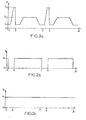
- each series of Figures 1a to 1c , 2a to 2c , and 3a to 3c represents the evolution of the intensity (I), the voltage (U) and the wire speed (Vf) as a function of the same time scale (t) in the abscissa for the CSC, STT and according to the invention, respectively. It should be noted, however, that the time scales (t) of each series of diagrams are not necessarily comparable with each other.
- a short-circuit period (CC) followed by an arc period is repeated as many times as necessary to effect the desired welding, that is to say the entire seal Welding.
- a transfer period occurs substantially between the instants A and A next and the short-circuit periods (CC) between the instants C and A.
- FIGS. 1a to 1c illustrate the succession of variations of the main parameters as a function of time t, for a CSC process according to the prior art, in particular the variation of the intensity I of the current circulating in the room ( Fig. 1a ), the voltage u between the part (s) to be welded and the consumable electrode ( Fig. 1b ), the displacement velocity Vf of the consumable electrode wire ( Fig. 1 C ).
- transfer cycle is a succession of steps between the deposition of two successive drops of metal. As mentioned above and in general, the deposition of a drop of metal takes place at the end of a short circuit.
- the voltage u a (arc voltage) is substantially constant and non-zero between the instants A and C and substantially equal to O between the instants C and A which correspond to the period of time during which the short -circuit.
- intensity I 1 is low between instants C and A, and kept low until A 1 . It then increases to reach a value I 2 , which causes the melting of the electrode wire, then down before the next instant C.
- the wire is animated by an alternative mechanical movement of advance / recoil. Its speed varies from a substantially constant speed V 1 , decreases to cancel and then reach a negative speed V 2 , for depositing the drop in the welding bath mechanically.
- the absolute value of V 2 is of the same order of magnitude as that of V 1 .
- the decrease in speed is controlled by the beginning of the short-circuit phase to reach the negative speed V 2 before the end of the short-circuit phase.
- the CSC process makes it possible, by an alternating movement of the unwinding of the wire, to reduce the energy at the ignition of the arc as well as to suppress the projections of metal.
- this method is limited, particularly in terms of the deposition rate, ie the metal volume of the deposited electrode wire, because of the obligation to remain in the short-circuit transfer mode and the relatively low transfer frequency, as explained above.
- FIGS. 2a to 2c illustrate, in the same way as Figures 1a to 1c , the succession of variations of the main parameters as a function of time t, for a STT method according to the prior art.
- the speed V 1 of the consumable electrode wire (see FIG. Figure 2c ) is constant and substantially equal to that according to a standard GMAW method.
- the particularity of the STT process essentially concerns the presence of a pulsation of intensity I, during the short-circuit period between the instants A and C, which makes it possible to reach an intensity value I 3 greater than the intensity during the arc period I 2 .
- a specific detection means sends an intensity pulse just before the reignition of the arc to initiate the necking of the liquid metal bridge formed between the fuse electrode and the solder bath and this, in the to avoid projections caused by a rebooting of the arc at high intensity.
- FIGS. 3a to 3b illustrate, in a manner identical to the preceding figures, the succession of variations of the main parameters as a function of time t, for a method according to the present invention.
- the arc welding method according to the invention comprises successive welding cycles over time (t) each comprising a regime or arc period (voltage u a between instants A and C) and a regime or period of short circuit (zero voltage between times A and C) where the liquid metal establishes the short circuit (DC) between the consumable electrode and one (or more) part to be welded.
- an intensity of arc I 2 is maintained for a period (A 3 to A 4 ) of the arc regime at the same time as the movement of the wire towards the workpiece is carried out.
- a substantially constant velocity V 1 so as to obtain a drop of molten metal at the end of the fuse electrode.
- the intensity (from I 4 ) is reduced during the short-circuit period to reach (at A) a minimum value I 1 lower than the arc intensity I 2 , thus concluding a cycle metal transfer at a low intensity and thereby eliminating the transfer instabilities of the molten metal during the reboot of the arc at the beginning of the next cycle.
- the peak of intensity I 4 very short associated with a rapid current drop I 1 allows the reboot of the arc at low intensity then removing all the characteristic projections of this phase.
- the stop of the wire during the short-circuit phase (CC), visible in figure 3c , allows the intensity peak to decrease with respect to a system where the wire continues to be unwound during this phase, as is the case with the STT method for example.
- the conventional operation of the intensity peak may require the use of a specific detection on the voltage in order to locate, during the short circuit, the necking of the filler metal and then be able to drop the intensity before rebooting the arc.
- This detection is complicated by the fact that the wire continues to advance during the short-circuit phase.
- a conventional intensity peak operation as with the STT method, has limitations in terms of maximum operating intensity due to the instabilities caused when a high unwinding speed (and thus a high average intensity) is applied during the short-circuiting phase.
- the intensity value I 4 during the short-circuit period is represented on the figure 3 greater than the intensity value I 2 occurring during the arc period.
- these values can be of substantially the same order of magnitude and depend essentially on the energy required to initiate the detachment of the drop of molten metal which vary according to the welded materials.
- the welding method according to the present invention has been successfully implemented and allowed the welding together of two sheets of 0.6 mm thickness joined end to end at a welding speed. of the order of 2.5 m / min.
- the protective gas used was a gaseous mixture of argon and CO 2 sold under the name Atal 5 by AIR LIQUID.
- the weld bead obtained was of good quality, having a good compactness and an absence of porosity, with very little deformation of the sheets.
- the device making it possible to implement the present invention can be simplified compared to that of a device with reciprocating movement of the wire since it is possible to dispense with means making it possible to impose a negative speed over the wire. consumable electrode.
Landscapes
- Engineering & Computer Science (AREA)
- Physics & Mathematics (AREA)
- Plasma & Fusion (AREA)
- Mechanical Engineering (AREA)
- Arc Welding Control (AREA)
- Arc Welding In General (AREA)
Claims (10)
- Lichtbogen-Schweißverfahren, bei dem eine Abschmelzelektrode verwendet wird, von der ein Ende nach und nach durch einen elektrischen Strom, mit dem die Elektrode versorgt wird, abgeschmolzen wird, wobei während der Zeit (t) Schweißzyklen (A-C-A) aufeinanderfolgen, die jeweils eine Lichtbogenzeit (ua; Zeitpunkte A-C) und eine Kurzschlusszeit (C-A), in der das flüssige Metall einen Kurzschluss (CC) zwischen dem abgeschmolzenen Ende der Elektrode und mindestens einem zu schweißenden Werkstück herstellt, umfassen, wobei jeder Zyklus folgende Schritte umfasst:a) Aufrechterhalten einer konstanten Lichtbogenstromstärke I2 während eines Zeitraums (A3 bis A4) der Lichtbogenzeit (A-C) zeitgleich zur Bewegung der Abschmelzelektrode in Richtung des zu schweißenden Werkstücks mit einer Geschwindigkeit V1;b) Verringerung der Stromstärke, um eine Mindeststromstärke I1 zu Beginn (bei C) der Kurzschlusszeit zu erreichen, wobei I1 < I2;c) Verringerung der Bewegungsgeschwindigkeit des Drahts der Abschmelzelektrode, um eine Mindestgeschwindigkeit V3 zu erreichen, wobei V3 < V1, Halten dieser Geschwindigkeit auf dem Wert V3 während mindestens eines Teils der Kurzschlusszeit (C-A);d) Erhöhung der Stromstärke während der Kurzschlusszeit (C-A), um einen Höchstwert I4 zu erreichen, wobei I4 ≥ I2;e) dann, im Anschluss an Schritt d), Verringerung der Stromstärke während der Kurzschlusszeit (C-A), um einen Mindestwert I1 zu erreichen, wobei I1 < I2, mit Halten dieser Stromstärke auf diesem konstanten Mindestwert I1.
- Verfahren nach Anspruch 1, dadurch gekennzeichnet, dass die Mindestgeschwindigkeit V3 im Wesentlichen null ist.
- Verfahren nach einem der Ansprüche 1 oder 2, dadurch gekennzeichnet, dass die Mindestgeschwindigkeit V3 zu Beginn der Lichtbogenzeit (bei A) beibehalten wird.
- Verfahren nach einem der vorhergehenden Ansprüche, dadurch gekennzeichnet, dass in Schritt d) die Erhöhung der Stromstärke (von I1 auf I4) während der Kurzschlusszeit während der Verringerung der Bewegungsgeschwindigkeit des Drahts der Abschmelzelektrode (von V1 auf V3) von Schritt c) erfolgt.
- Verfahren nach einem der vorhergehenden Ansprüche, dadurch gekennzeichnet, dass während der Kurzschlusszeit die Stromstärke (von I1 auf I4) erhöht und die Bewegungsgeschwindigkeit des Drahts verringert wird, bis eine Mindestgeschwindigkeit V3 erreicht ist, wodurch die Ablösung von mindestens einem Tropfen geschmolzenen Metalls bewirkt wird.
- Verfahren nach einem der vorhergehenden Ansprüche, dadurch gekennzeichnet, dass der Höchstwert der Stromstärke I4 während eines Plateaus (C2 bis C3) gehalten wird, während die Bewegungsgeschwindigkeit des Drahts der Abschmelzelektrode auf der Mindestgeschwindigkeit V3 gehalten wird.
- Verfahren nach einem der vorhergehenden Ansprüche, dadurch gekennzeichnet, dass der Spannungswert gemessen wird, um die Absenkung der Stromstärke vor der erneuten Herstellung des Lichtbogens auszulösen, während die Bewegungsgeschwindigkeit des Drahts der Abschmelzelektrode auf der Mindestgeschwindigkeit V3 gehalten wird.
- Verfahren nach einem der vorhergehenden Ansprüche, dadurch gekennzeichnet, dass während des Schweißens ein Gasschutz verwendet wird und das Schweißen von einem oder mehreren metallischen Werkstücken aus einem Metall oder einer Metalllegierung ausgewählt aus beschichteten oder nicht beschichteten Kohlenstoffstählen, beschichteten oder nicht beschichteten rostfreien Stählen und beschichtetem oder nicht beschichtetem Aluminium oder Titan erfolgt.
- Vorrichtung zur Steuerung der Stromversorgung eines Generators zum Kurzschluss-Metallübertragungs-Lichtbogenschweißen, bei dem eine Abschmelzelektrode verwendet wird, wobei der Generator Mittel zur Stromversorgung umfasst, wobei die Vorrichtung eine Steuerschaltung für die Ausführung des Verfahrens nach einem der Ansprüche 1 bis 8 umfasst.
- MIG/MAG-Schweißstromgenerator, der Mittel zur Stromversorgung und eine Vorrichtung zur Steuerung der Mittel zur Stromversorgung nach Anspruch 9 umfasst.
Applications Claiming Priority (1)
| Application Number | Priority Date | Filing Date | Title |
|---|---|---|---|
| FR0758825A FR2923167B1 (fr) | 2007-11-06 | 2007-11-06 | Procede de soudage a l'arc par court-circuit avec electrode fusible |
Publications (4)
| Publication Number | Publication Date |
|---|---|
| EP2058078A1 EP2058078A1 (de) | 2009-05-13 |
| EP2058078B1 true EP2058078B1 (de) | 2012-06-27 |
| EP2058078B9 EP2058078B9 (de) | 2014-02-26 |
| EP2058078B2 EP2058078B2 (de) | 2019-07-24 |
Family
ID=39529326
Family Applications (1)
| Application Number | Title | Priority Date | Filing Date |
|---|---|---|---|
| EP08168171.0A Active EP2058078B2 (de) | 2007-11-06 | 2008-11-03 | Lichtbogen-Schweißverfahren durch Kurzschluss mit abschmelzender Schmelzelektrode |
Country Status (5)
| Country | Link |
|---|---|
| US (1) | US20090114631A1 (de) |
| EP (1) | EP2058078B2 (de) |
| JP (1) | JP2009113117A (de) |
| CA (1) | CA2642057A1 (de) |
| FR (1) | FR2923167B1 (de) |
Families Citing this family (14)
| Publication number | Priority date | Publication date | Assignee | Title |
|---|---|---|---|---|
| CN102149502A (zh) * | 2008-09-30 | 2011-08-10 | 大阳日酸株式会社 | 钢板的气体保护电弧钎焊方法 |
| EP2338628B2 (de) | 2009-07-10 | 2023-02-15 | Panasonic Intellectual Property Management Co., Ltd. | Verfahren zur steuerung einer lichtbogenschweissung und lichtbogenschweissvorrichtung |
| FR2949364B1 (fr) | 2009-08-27 | 2011-10-28 | Air Liquide | Dispositif et procede de devidage d'au moins un fil de soudage |
| EP2407266B1 (de) * | 2009-11-25 | 2017-05-10 | Panasonic Intellectual Property Management Co., Ltd. | Schweissverfahren und schweissvorrichtung |
| FR2977818B1 (fr) | 2011-07-11 | 2014-05-23 | Air Liquide Welding France | Procede de soudage a l'arc avec electrode consommable |
| US9050676B2 (en) * | 2012-03-02 | 2015-06-09 | Lincoln Global, Inc. | Apparatus and method for starting arc welding process |
| EP3342521B1 (de) * | 2012-03-16 | 2019-08-21 | Panasonic Intellectual Property Management Co., Ltd. | Lichtbogenschweissvorrichtung |
| JP6152588B2 (ja) * | 2013-07-10 | 2017-06-28 | パナソニックIpマネジメント株式会社 | アーク溶接制御方法およびアーク溶接装置 |
| WO2016056563A1 (ja) * | 2014-10-06 | 2016-04-14 | 新日鐵住金株式会社 | アークスポット溶接方法及びそれを実行する溶接装置 |
| US10179369B2 (en) | 2015-10-27 | 2019-01-15 | Lincoln Global, Inc. | Welding system for AC welding with reduced spatter |
| JP6778858B2 (ja) * | 2016-03-29 | 2020-11-04 | パナソニックIpマネジメント株式会社 | アーク溶接制御方法 |
| CN110049844B (zh) * | 2017-01-24 | 2021-04-06 | 株式会社达谊恒 | 电弧焊接控制方法 |
| JP6850222B2 (ja) * | 2017-08-22 | 2021-03-31 | 株式会社神戸製鋼所 | パルスアーク溶接方法、溶接物の製造方法および溶接用電源装置 |
| EP3815828A1 (de) * | 2019-11-04 | 2021-05-05 | FRONIUS INTERNATIONAL GmbH | Verfahren und vorrichtung zum schweissen einer schweissnaht |
Family Cites Families (10)
| Publication number | Priority date | Publication date | Assignee | Title |
|---|---|---|---|---|
| US5148001A (en) | 1986-12-11 | 1992-09-15 | The Lincoln Electric Company | System and method of short circuiting arc welding |
| US5001326A (en) † | 1986-12-11 | 1991-03-19 | The Lincoln Electric Company | Apparatus and method of controlling a welding cycle |
| DE4091340C2 (de) * | 1989-08-02 | 2000-06-21 | Mitsubishi Electric Corp | Impulsschweißvorrichtung |
| DE19738785C2 (de) † | 1997-09-04 | 2001-12-13 | Leipold & Co Gmbh | Vorrichtung zum Lichtbogenschweißen mit abschmelzender Elektrode |
| US6051810A (en) * | 1998-01-09 | 2000-04-18 | Lincoln Global, Inc. | Short circuit welder |
| WO2000054924A1 (fr) * | 1999-03-18 | 2000-09-21 | Kabushiki Kaisha Yaskawa Denki | Procede de soudage a l'arc a electrode fusible et dispositif associe |
| AT409832B (de) † | 1999-04-26 | 2002-11-25 | Fronius Schweissmasch Prod | Schweissverfahren und schweissgerät zur durchführung des schweissverfahrens |
| AUPS274002A0 (en) * | 2002-06-03 | 2002-06-20 | University Of Wollongong, The | Control method and system for metal arc welding |
| US6969823B2 (en) * | 2002-07-23 | 2005-11-29 | Illinois Tool Works Inc. | Method and apparatus for controlling a welding system |
| JP4211793B2 (ja) † | 2006-02-17 | 2009-01-21 | パナソニック株式会社 | アーク溶接制御方法およびアーク溶接装置 |
-
2007
- 2007-11-06 FR FR0758825A patent/FR2923167B1/fr active Active
-
2008
- 2008-10-24 CA CA002642057A patent/CA2642057A1/fr not_active Abandoned
- 2008-10-30 US US12/261,702 patent/US20090114631A1/en not_active Abandoned
- 2008-11-03 EP EP08168171.0A patent/EP2058078B2/de active Active
- 2008-11-05 JP JP2008284664A patent/JP2009113117A/ja active Pending
Also Published As
| Publication number | Publication date |
|---|---|
| FR2923167A1 (fr) | 2009-05-08 |
| JP2009113117A (ja) | 2009-05-28 |
| EP2058078B9 (de) | 2014-02-26 |
| FR2923167B1 (fr) | 2010-03-26 |
| EP2058078B2 (de) | 2019-07-24 |
| US20090114631A1 (en) | 2009-05-07 |
| EP2058078A1 (de) | 2009-05-13 |
| CA2642057A1 (fr) | 2009-05-06 |
Similar Documents
| Publication | Publication Date | Title |
|---|---|---|
| EP2058078B1 (de) | Lichtbogen-Schweißverfahren durch Kurzschluss mit abschmelzender Schmelzelektrode | |
| EP2605880B1 (de) | Bogenschweissvorrichtung und -verfahren unter verwendung eines mig/mag-brenners in kombination mit einem wig-brenner | |
| EP0909604B1 (de) | Verfahren zum modulierten MIG Spritzschweissen | |
| US20080264923A1 (en) | Welding system and method with improved waveform | |
| EP2802435B1 (de) | Mig/wig oder mag/wig hybrid-schweissvorrichtung | |
| EP2892674B1 (de) | Lichtbogenschweissvorrichtung mit automatischer auswahl der metallübertragung | |
| EP1632306A1 (de) | Hybrides Laser-MIGschweißverfahren mit hoher Drahtgeschwindigkeit | |
| EP1216780B1 (de) | Verfahren und Vorrichtung zum Impulslichtbogenschweissen | |
| EP3969213B1 (de) | Generatives herstellungsverfahren für ein metallwerkstück | |
| EP2939782B1 (de) | Verfahren und anlage zum lichtbogen-plasmaschneiden mit verbessertem bohrzyklus | |
| EP2546017B1 (de) | Lichtbogenschweißverfahren und -vorrichtung mit Abschmelzelektrode unter Verwendung von Kurzschlussschweisszyklen und pulsenden Transferierschweisszyklen | |
| EP0924017B1 (de) | Vorrichtung und Verfahren zum Plasmalichtbogenschweissen mit variabeler Polarität | |
| FR3012759A3 (fr) | Systeme pour et procede de soudage et/ou de rechargement avec fil additionnel | |
| EP2248621B1 (de) | Verfahren zum Anfangen eines Lichtbogenschweissens mit Verspätung des Eintritt in der gepulsten Phase | |
| EP4015126B1 (de) | Verfahren zum heften von zwei blechen oder teilen, entsprechendes schweissverfahren und schweissgerät | |
| EP0951376B1 (de) | Verfahren und vorrichtung zum schweissen mit einer gepulsten laserstrahlung | |
| EP1655096B1 (de) | Lichtbogenschweissanlage mit mehreren Brennern mit nichtabschmelzender Elektrode und Zweifach-Fluxschutz für Rohrschweissen, jeder brenner mit der in dem Plan der inneren Düse liegenden Elektrodespitze | |
| FR2935277A1 (fr) | Procede de soudage a l'arc a double courant de base. | |
| FR2798083A1 (fr) | Installation et procede de travail a l'arc plasma a polarite inverse | |
| FR2974526A1 (fr) | Dispositif et procede de soudage mig/mag |
Legal Events
| Date | Code | Title | Description |
|---|---|---|---|
| PUAI | Public reference made under article 153(3) epc to a published international application that has entered the european phase |
Free format text: ORIGINAL CODE: 0009012 |
|
| AK | Designated contracting states |
Kind code of ref document: A1 Designated state(s): AT BE BG CH CY CZ DE DK EE ES FI FR GB GR HR HU IE IS IT LI LT LU LV MC MT NL NO PL PT RO SE SI SK TR |
|
| AX | Request for extension of the european patent |
Extension state: AL BA MK RS |
|
| 17P | Request for examination filed |
Effective date: 20091113 |
|
| AKX | Designation fees paid |
Designated state(s): AT BE BG CH CY CZ DE DK EE ES FI FR GB GR HR HU IE IS IT LI LT LU LV MC MT NL NO PL PT RO SE SI SK TR |
|
| GRAP | Despatch of communication of intention to grant a patent |
Free format text: ORIGINAL CODE: EPIDOSNIGR1 |
|
| GRAS | Grant fee paid |
Free format text: ORIGINAL CODE: EPIDOSNIGR3 |
|
| GRAA | (expected) grant |
Free format text: ORIGINAL CODE: 0009210 |
|
| AK | Designated contracting states |
Kind code of ref document: B1 Designated state(s): AT BE BG CH CY CZ DE DK EE ES FI FR GB GR HR HU IE IS IT LI LT LU LV MC MT NL NO PL PT RO SE SI SK TR |
|
| REG | Reference to a national code |
Ref country code: GB Ref legal event code: FG4D Free format text: NOT ENGLISH |
|
| REG | Reference to a national code |
Ref country code: CH Ref legal event code: EP |
|
| REG | Reference to a national code |
Ref country code: AT Ref legal event code: REF Ref document number: 563884 Country of ref document: AT Kind code of ref document: T Effective date: 20120715 |
|
| REG | Reference to a national code |
Ref country code: IE Ref legal event code: FG4D Free format text: LANGUAGE OF EP DOCUMENT: FRENCH |
|
| REG | Reference to a national code |
Ref country code: DE Ref legal event code: R096 Ref document number: 602008016703 Country of ref document: DE Effective date: 20120823 |
|
| PG25 | Lapsed in a contracting state [announced via postgrant information from national office to epo] |
Ref country code: NO Free format text: LAPSE BECAUSE OF FAILURE TO SUBMIT A TRANSLATION OF THE DESCRIPTION OR TO PAY THE FEE WITHIN THE PRESCRIBED TIME-LIMIT Effective date: 20120927 Ref country code: LT Free format text: LAPSE BECAUSE OF FAILURE TO SUBMIT A TRANSLATION OF THE DESCRIPTION OR TO PAY THE FEE WITHIN THE PRESCRIBED TIME-LIMIT Effective date: 20120627 Ref country code: SE Free format text: LAPSE BECAUSE OF FAILURE TO SUBMIT A TRANSLATION OF THE DESCRIPTION OR TO PAY THE FEE WITHIN THE PRESCRIBED TIME-LIMIT Effective date: 20120627 Ref country code: FI Free format text: LAPSE BECAUSE OF FAILURE TO SUBMIT A TRANSLATION OF THE DESCRIPTION OR TO PAY THE FEE WITHIN THE PRESCRIBED TIME-LIMIT Effective date: 20120627 |
|
| REG | Reference to a national code |
Ref country code: NL Ref legal event code: VDEP Effective date: 20120627 |
|
| REG | Reference to a national code |
Ref country code: AT Ref legal event code: MK05 Ref document number: 563884 Country of ref document: AT Kind code of ref document: T Effective date: 20120627 |
|
| REG | Reference to a national code |
Ref country code: LT Ref legal event code: MG4D Effective date: 20120627 |
|
| PG25 | Lapsed in a contracting state [announced via postgrant information from national office to epo] |
Ref country code: LV Free format text: LAPSE BECAUSE OF FAILURE TO SUBMIT A TRANSLATION OF THE DESCRIPTION OR TO PAY THE FEE WITHIN THE PRESCRIBED TIME-LIMIT Effective date: 20120627 Ref country code: HR Free format text: LAPSE BECAUSE OF FAILURE TO SUBMIT A TRANSLATION OF THE DESCRIPTION OR TO PAY THE FEE WITHIN THE PRESCRIBED TIME-LIMIT Effective date: 20120627 Ref country code: SI Free format text: LAPSE BECAUSE OF FAILURE TO SUBMIT A TRANSLATION OF THE DESCRIPTION OR TO PAY THE FEE WITHIN THE PRESCRIBED TIME-LIMIT Effective date: 20120627 Ref country code: GR Free format text: LAPSE BECAUSE OF FAILURE TO SUBMIT A TRANSLATION OF THE DESCRIPTION OR TO PAY THE FEE WITHIN THE PRESCRIBED TIME-LIMIT Effective date: 20120928 |
|
| PG25 | Lapsed in a contracting state [announced via postgrant information from national office to epo] |
Ref country code: IS Free format text: LAPSE BECAUSE OF FAILURE TO SUBMIT A TRANSLATION OF THE DESCRIPTION OR TO PAY THE FEE WITHIN THE PRESCRIBED TIME-LIMIT Effective date: 20121027 Ref country code: RO Free format text: LAPSE BECAUSE OF FAILURE TO SUBMIT A TRANSLATION OF THE DESCRIPTION OR TO PAY THE FEE WITHIN THE PRESCRIBED TIME-LIMIT Effective date: 20120627 Ref country code: CZ Free format text: LAPSE BECAUSE OF FAILURE TO SUBMIT A TRANSLATION OF THE DESCRIPTION OR TO PAY THE FEE WITHIN THE PRESCRIBED TIME-LIMIT Effective date: 20120627 Ref country code: CY Free format text: LAPSE BECAUSE OF FAILURE TO SUBMIT A TRANSLATION OF THE DESCRIPTION OR TO PAY THE FEE WITHIN THE PRESCRIBED TIME-LIMIT Effective date: 20120627 Ref country code: EE Free format text: LAPSE BECAUSE OF FAILURE TO SUBMIT A TRANSLATION OF THE DESCRIPTION OR TO PAY THE FEE WITHIN THE PRESCRIBED TIME-LIMIT Effective date: 20120627 Ref country code: AT Free format text: LAPSE BECAUSE OF FAILURE TO SUBMIT A TRANSLATION OF THE DESCRIPTION OR TO PAY THE FEE WITHIN THE PRESCRIBED TIME-LIMIT Effective date: 20120627 Ref country code: SK Free format text: LAPSE BECAUSE OF FAILURE TO SUBMIT A TRANSLATION OF THE DESCRIPTION OR TO PAY THE FEE WITHIN THE PRESCRIBED TIME-LIMIT Effective date: 20120627 |
|
| PG25 | Lapsed in a contracting state [announced via postgrant information from national office to epo] |
Ref country code: PT Free format text: LAPSE BECAUSE OF FAILURE TO SUBMIT A TRANSLATION OF THE DESCRIPTION OR TO PAY THE FEE WITHIN THE PRESCRIBED TIME-LIMIT Effective date: 20121029 Ref country code: PL Free format text: LAPSE BECAUSE OF FAILURE TO SUBMIT A TRANSLATION OF THE DESCRIPTION OR TO PAY THE FEE WITHIN THE PRESCRIBED TIME-LIMIT Effective date: 20120627 Ref country code: IT Free format text: LAPSE BECAUSE OF FAILURE TO SUBMIT A TRANSLATION OF THE DESCRIPTION OR TO PAY THE FEE WITHIN THE PRESCRIBED TIME-LIMIT Effective date: 20120627 |
|
| PG25 | Lapsed in a contracting state [announced via postgrant information from national office to epo] |
Ref country code: NL Free format text: LAPSE BECAUSE OF FAILURE TO SUBMIT A TRANSLATION OF THE DESCRIPTION OR TO PAY THE FEE WITHIN THE PRESCRIBED TIME-LIMIT Effective date: 20120627 |
|
| PLBI | Opposition filed |
Free format text: ORIGINAL CODE: 0009260 |
|
| PG25 | Lapsed in a contracting state [announced via postgrant information from national office to epo] |
Ref country code: DK Free format text: LAPSE BECAUSE OF FAILURE TO SUBMIT A TRANSLATION OF THE DESCRIPTION OR TO PAY THE FEE WITHIN THE PRESCRIBED TIME-LIMIT Effective date: 20120627 Ref country code: ES Free format text: LAPSE BECAUSE OF FAILURE TO SUBMIT A TRANSLATION OF THE DESCRIPTION OR TO PAY THE FEE WITHIN THE PRESCRIBED TIME-LIMIT Effective date: 20121008 |
|
| 26 | Opposition filed |
Opponent name: FRONIUS INTERNATIONAL GMBH Effective date: 20130322 |
|
| PLAX | Notice of opposition and request to file observation + time limit sent |
Free format text: ORIGINAL CODE: EPIDOSNOBS2 |
|
| REG | Reference to a national code |
Ref country code: DE Ref legal event code: R026 Ref document number: 602008016703 Country of ref document: DE Effective date: 20130322 |
|
| PLBB | Reply of patent proprietor to notice(s) of opposition received |
Free format text: ORIGINAL CODE: EPIDOSNOBS3 |
|
| PG25 | Lapsed in a contracting state [announced via postgrant information from national office to epo] |
Ref country code: BG Free format text: LAPSE BECAUSE OF FAILURE TO SUBMIT A TRANSLATION OF THE DESCRIPTION OR TO PAY THE FEE WITHIN THE PRESCRIBED TIME-LIMIT Effective date: 20120927 |
|
| REG | Reference to a national code |
Ref country code: IE Ref legal event code: MM4A |
|
| PG25 | Lapsed in a contracting state [announced via postgrant information from national office to epo] |
Ref country code: IE Free format text: LAPSE BECAUSE OF NON-PAYMENT OF DUE FEES Effective date: 20121103 |
|
| PG25 | Lapsed in a contracting state [announced via postgrant information from national office to epo] |
Ref country code: MT Free format text: LAPSE BECAUSE OF FAILURE TO SUBMIT A TRANSLATION OF THE DESCRIPTION OR TO PAY THE FEE WITHIN THE PRESCRIBED TIME-LIMIT Effective date: 20120627 |
|
| RAP2 | Party data changed (patent owner data changed or rights of a patent transferred) |
Owner name: AIR LIQUIDE WELDING FRANCE |
|
| PG25 | Lapsed in a contracting state [announced via postgrant information from national office to epo] |
Ref country code: TR Free format text: LAPSE BECAUSE OF FAILURE TO SUBMIT A TRANSLATION OF THE DESCRIPTION OR TO PAY THE FEE WITHIN THE PRESCRIBED TIME-LIMIT Effective date: 20120627 Ref country code: MC Free format text: LAPSE BECAUSE OF NON-PAYMENT OF DUE FEES Effective date: 20121130 |
|
| PG25 | Lapsed in a contracting state [announced via postgrant information from national office to epo] |
Ref country code: LU Free format text: LAPSE BECAUSE OF NON-PAYMENT OF DUE FEES Effective date: 20121103 |
|
| PG25 | Lapsed in a contracting state [announced via postgrant information from national office to epo] |
Ref country code: HU Free format text: LAPSE BECAUSE OF FAILURE TO SUBMIT A TRANSLATION OF THE DESCRIPTION OR TO PAY THE FEE WITHIN THE PRESCRIBED TIME-LIMIT Effective date: 20081103 |
|
| RDAF | Communication despatched that patent is revoked |
Free format text: ORIGINAL CODE: EPIDOSNREV1 |
|
| APAH | Appeal reference modified |
Free format text: ORIGINAL CODE: EPIDOSCREFNO |
|
| APBM | Appeal reference recorded |
Free format text: ORIGINAL CODE: EPIDOSNREFNO |
|
| APBP | Date of receipt of notice of appeal recorded |
Free format text: ORIGINAL CODE: EPIDOSNNOA2O |
|
| APAL | Date of receipt of statement of grounds of an appeal modified |
Free format text: ORIGINAL CODE: EPIDOSCNOA3O |
|
| APBQ | Date of receipt of statement of grounds of appeal recorded |
Free format text: ORIGINAL CODE: EPIDOSNNOA3O |
|
| APAH | Appeal reference modified |
Free format text: ORIGINAL CODE: EPIDOSCREFNO |
|
| APAH | Appeal reference modified |
Free format text: ORIGINAL CODE: EPIDOSCREFNO |
|
| REG | Reference to a national code |
Ref country code: FR Ref legal event code: PLFP Year of fee payment: 8 |
|
| REG | Reference to a national code |
Ref country code: FR Ref legal event code: PLFP Year of fee payment: 9 |
|
| REG | Reference to a national code |
Ref country code: FR Ref legal event code: PLFP Year of fee payment: 10 |
|
| PGFP | Annual fee paid to national office [announced via postgrant information from national office to epo] |
Ref country code: BE Payment date: 20171120 Year of fee payment: 10 Ref country code: CH Payment date: 20171120 Year of fee payment: 10 Ref country code: GB Payment date: 20171123 Year of fee payment: 10 |
|
| APBU | Appeal procedure closed |
Free format text: ORIGINAL CODE: EPIDOSNNOA9O |
|
| PUAH | Patent maintained in amended form |
Free format text: ORIGINAL CODE: 0009272 |
|
| STAA | Information on the status of an ep patent application or granted ep patent |
Free format text: STATUS: PATENT MAINTAINED AS AMENDED |
|
| REG | Reference to a national code |
Ref country code: CH Ref legal event code: PL |
|
| REG | Reference to a national code |
Ref country code: DE Ref legal event code: R081 Ref document number: 602008016703 Country of ref document: DE Owner name: AIR LIQUIDE WELDING FRANCE, FR Free format text: FORMER OWNERS: AIR LIQUIDE WELDING FRANCE, PARIS, FR; L'AIR LIQUIDE, SOCIETE ANONYME POUR L'ETUDE ET L'EXPLOITATION DES PROCEDES GEORGES CLAUDE, PARIS, FR |
|
| 27A | Patent maintained in amended form |
Effective date: 20190724 |
|
| AK | Designated contracting states |
Kind code of ref document: B2 Designated state(s): AT BE BG CH CY CZ DE DK EE ES FI FR GB GR HR HU IE IS IT LI LT LU LV MC MT NL NO PL PT RO SE SI SK TR |
|
| GBPC | Gb: european patent ceased through non-payment of renewal fee |
Effective date: 20181103 |
|
| REG | Reference to a national code |
Ref country code: DE Ref legal event code: R102 Ref document number: 602008016703 Country of ref document: DE |
|
| REG | Reference to a national code |
Ref country code: BE Ref legal event code: MM Effective date: 20181130 |
|
| PG25 | Lapsed in a contracting state [announced via postgrant information from national office to epo] |
Ref country code: LI Free format text: LAPSE BECAUSE OF NON-PAYMENT OF DUE FEES Effective date: 20181130 Ref country code: CH Free format text: LAPSE BECAUSE OF NON-PAYMENT OF DUE FEES Effective date: 20181130 |
|
| PG25 | Lapsed in a contracting state [announced via postgrant information from national office to epo] |
Ref country code: BE Free format text: LAPSE BECAUSE OF NON-PAYMENT OF DUE FEES Effective date: 20181130 |
|
| PG25 | Lapsed in a contracting state [announced via postgrant information from national office to epo] |
Ref country code: GB Free format text: LAPSE BECAUSE OF NON-PAYMENT OF DUE FEES Effective date: 20181103 |
|
| PGFP | Annual fee paid to national office [announced via postgrant information from national office to epo] |
Ref country code: DE Payment date: 20251118 Year of fee payment: 18 |
|
| PGFP | Annual fee paid to national office [announced via postgrant information from national office to epo] |
Ref country code: FR Payment date: 20251125 Year of fee payment: 18 |