EP2056708B1 - Capteur de pression sans fil implantable microfabriqué destiné à être utilisé dans des applications biomédicales, et procédés de mesure de pression et d'implantation de capteur - Google Patents
Capteur de pression sans fil implantable microfabriqué destiné à être utilisé dans des applications biomédicales, et procédés de mesure de pression et d'implantation de capteur Download PDFInfo
- Publication number
- EP2056708B1 EP2056708B1 EP07814555.4A EP07814555A EP2056708B1 EP 2056708 B1 EP2056708 B1 EP 2056708B1 EP 07814555 A EP07814555 A EP 07814555A EP 2056708 B1 EP2056708 B1 EP 2056708B1
- Authority
- EP
- European Patent Office
- Prior art keywords
- capacitor
- substrate
- flexible member
- pressure
- inductor
- Prior art date
- Legal status (The legal status is an assumption and is not a legal conclusion. Google has not performed a legal analysis and makes no representation as to the accuracy of the status listed.)
- Not-in-force
Links
Images


Classifications
-
- A—HUMAN NECESSITIES
- A61—MEDICAL OR VETERINARY SCIENCE; HYGIENE
- A61B—DIAGNOSIS; SURGERY; IDENTIFICATION
- A61B3/00—Apparatus for testing the eyes; Instruments for examining the eyes
- A61B3/10—Objective types, i.e. instruments for examining the eyes independent of the patients' perceptions or reactions
- A61B3/16—Objective types, i.e. instruments for examining the eyes independent of the patients' perceptions or reactions for measuring intraocular pressure, e.g. tonometers
-
- A—HUMAN NECESSITIES
- A61—MEDICAL OR VETERINARY SCIENCE; HYGIENE
- A61B—DIAGNOSIS; SURGERY; IDENTIFICATION
- A61B5/00—Measuring for diagnostic purposes; Identification of persons
- A61B5/02—Detecting, measuring or recording pulse, heart rate, blood pressure or blood flow; Combined pulse/heart-rate/blood pressure determination; Evaluating a cardiovascular condition not otherwise provided for, e.g. using combinations of techniques provided for in this group with electrocardiography or electroauscultation; Heart catheters for measuring blood pressure
- A61B5/021—Measuring pressure in heart or blood vessels
- A61B5/0215—Measuring pressure in heart or blood vessels by means inserted into the body
-
- A—HUMAN NECESSITIES
- A61—MEDICAL OR VETERINARY SCIENCE; HYGIENE
- A61B—DIAGNOSIS; SURGERY; IDENTIFICATION
- A61B5/00—Measuring for diagnostic purposes; Identification of persons
- A61B5/03—Detecting, measuring or recording fluid pressure within the body other than blood pressure, e.g. cerebral pressure; Measuring pressure in body tissues or organs
-
- G—PHYSICS
- G01—MEASURING; TESTING
- G01L—MEASURING FORCE, STRESS, TORQUE, WORK, MECHANICAL POWER, MECHANICAL EFFICIENCY, OR FLUID PRESSURE
- G01L9/00—Measuring steady of quasi-steady pressure of fluid or fluent solid material by electric or magnetic pressure-sensitive elements; Transmitting or indicating the displacement of mechanical pressure-sensitive elements, used to measure the steady or quasi-steady pressure of a fluid or fluent solid material, by electric or magnetic means
- G01L9/0041—Transmitting or indicating the displacement of flexible diaphragms
- G01L9/0072—Transmitting or indicating the displacement of flexible diaphragms using variations in capacitance
-
- A—HUMAN NECESSITIES
- A61—MEDICAL OR VETERINARY SCIENCE; HYGIENE
- A61B—DIAGNOSIS; SURGERY; IDENTIFICATION
- A61B5/00—Measuring for diagnostic purposes; Identification of persons
- A61B5/0002—Remote monitoring of patients using telemetry, e.g. transmission of vital signals via a communication network
- A61B5/0031—Implanted circuitry
Definitions
- the field of the invention relates to pressure sensors and, more particularly, to microfabricated implantable pressure sensors for use in biomedical applications including monitoring of intraocular pressure.
- Pressure sensor devices have been used to study various physiological conditions in biomedical applications.
- One known application is to monitor intraocular pressure, for example, in connection with treatment of glaucoma.
- Glaucoma is a well known ocular disease that affects millions of people. Persons afflicted with this disease require treatment for life. The disease causes visual field loss and if left untreated, may result in permanent loss of vision, and is a primary cause of blindness in the United States and elsewhere.
- Intraocular pressure typically ranges from about 10 to about 21 mm Hg, e.g., about 15 mm Hg.
- Intraocular pressures of eyes of patients having glaucoma often exceed 21 mm, although glaucoma may exist when intraocular pressures are at lower levels. Elevated intraocular pressures are believed to be responsible for slowly damaging the optic nerve which, in turn, can cause blind spots in the field of vision. Total blindness may occur if the entire optic nerve is damaged.
- One known manner of measuring intraocular pressure is to use an external pressure measurement device that acquires intraocular pressure readings from outside of the eye.
- One known pressure measurement device is known as a tonometer, which measures an external deformation of an eye and relates that measurement to intraocular pressure.
- Such external measurement devices may not have the desired level of accuracy since they operate in an external environment rather than within the eye itself. Further, such devices do not provide for continuous monitoring of intraocular pressure since a tonometer must be utilized each time intraocular pressure is to be determined and, therefore, provides discontinuous intraocular pressure monitoring.
- an external instrument generates a signal to remotely energize an in vivo intraocular pressure sensor. The response generated by the in vivo sensor is measured and correlated to intraocular pressure.
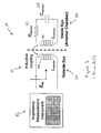
- a known intraocular telemetry system 10 includes an external system 20 and an internal or implanted intraocular sensing circuit 30.
- the external system 20 includes an excitation circuit 21 and a measurement device 22.
- the sensing circuit 30 typically includes a resistor (R sensor ) 33 and an inductor (L sensor ) 34 and a capacitor (C sensor ) 35.
- the capacitor 35 may be configured to vary with the intraocular pressure applied to the capacitor 35.
- the excitation circuit 21 typically includes an inductor (L) 24.
- the excitation circuit 20 generates energy, which is delivered to the sensing circuit 30 by inductive coupling between the inductors 24, 34, thereby energizing the sensing circuit 30.
- the resulting response (e.g., resonant frequency or impedance) of the sensing circuit 30 is measured by the measurement device 22 and correlated to intraocular pressure.
- the implanted sensing circuit 30 is essentially an RLC resonance circuit.
- a change of capacitance causes a shift in resonant frequency of the implanted sensor circuit 30, which can be wirelessly measured by the external measurement device 22. Examples of such intraocular implants and telemetry systems are described in U.S. Patent No. 6,579,235 to Abita et al.
- One known capacitor for use in intraocular pressure sensors is manufactured using MEMS technologies and includes a membrane, a flat bottom portion and a chamber. The capacitor is part of a pressure sensor that is implantable to monitor pressures through a remote telemetry connection.
- Another known capacitor device used in pressure sensors is referred to as a comb-drive capacitor unit.
- One known capacitor unit is described in "Design and Simulation of a MEMS-Based Comb-Drive Pressure Sensor for Pediatric PostOperative Monitoring Applications," by Duck-Bong Seo et al. Seo et al. Seo et al. describe an implantable MEMS-based pressure sensor to monitor pressures through a remote telemetry connection in the context of monitoring pressures of the right side of the heart following surgery. Seo et al. show a flat membrane and a comb drive and explain that a change of overlapping area changes the capacitance of the device, and that no bending or other deformation of the membrane was found for the comb-drive sensor.
- While known sensor devices and telemetry systems may provide some improvements over known external pressure measurement devices, they can be improved.
- certain known sensor devices present performance, biocompatibility, packaging and/or size challenges.
- Certain known devices also lack sensitivities and detection ranges suitable for various biomedical applications.
- certain known devices utilize wafer bonding techniques, which typically require additional fabrication time and result in larger or thicker devices. Additionally, bonding often results in reduced yield rate, e.g. due precise component alignment requirements. Thus, devices that are fabricated using wafer bonding are not desirable.
- Certain known devices also may not be adaptable to commercial fabrication on a large scale.
- the inductor element of the implanted sensor circuit can be improved to provide a more effective sensor circuit and more accurate intraocular pressure determinations.
- Known devices may also require larger incisions or blades for implantation of sensor devices due to their large size. Such incisions are not desirable.
- certain known implants require sutures to remain implanted in the eye, which are also not desirable.
- implantable sensor devices that can be fabricated using known micromachining and MEMS technologies. It would also be desirable to have implantable sensor devices that are sufficiently small or miniature in size so that they may be delivered through a needle rather than through a large incision using a blade. It would also be desirable to have sensor devices that may be implanted without the need for sutures and in various locations of an eye. Further, it would also be desirable to have biocompatible and implantable microfabricated sensor devices with improved capacitor and inductor components for enhanced sensitivity, dynamic range and accuracy. It would also be desirable to continuously and passively monitor intraocular pressure by telemetry using such sensor devices. Such capabilities would enhance biomedical applications and pressure-dependent physical conditions and diseases including monitoring of intraocular pressure.
- the invention is directed to a variable capacitor according to claim 1.
- a microfabricated implantable pressure sensor can include a variable capacitor and an inductor.
- the variable capacitor and the inductor are electrically connected to each other.
- the variable capacitor includes a substrate, a flexible member and a plurality of capacitor elements.
- the substrate defines a plurality of channels, and edges of the flexible member are on the substrate.
- a middle portion of the flexible member is raised above the substrate, thereby defining a chamber.
- Capacitor elements extend indirectly from the flexible member. Fluid pressure changes on the middle portion cause the middle portion to move, thereby causing the capacitor elements to move within respective channels and causing capacitance to vary with changes in an overlapping area of the capacitor elements and the substrate.
- An electrical circuit including the variable capacitor and the inductor can generate a detectable resonant frequency shift in response to a change of fluid pressure on an outer surface of the flexible member.
- a microfabricated implantable pressure sensor can include a substrate, a flexible member disposed on the substrate, a variable capacitor and a variable inductor.
- a chamber is defined between the substrate and the flexible member, and the variable capacitor and variable inductor are electrically connected to each other.
- the flexible member carries components of the variable capacitor and also carries components of the variable inductor. With this configuration, the flexible member can be moved in response to fluid pressure changes on an outer surface of the flexible member to vary capacitance and inductance.
- Capacitor elements extend indirectly from a flexible member by an indirect connection, e.g., by an indirect connector including an intermediate member and a cross bar or member.
- the capacitor elements are carried by the cross bar or member, which is connected to or extends from an intermediate member, which extends between the flexible member and the cross bar or member.
- the middle portion of the flexible member may be deformed in a non-linear manner, e.g., to assume a bowl-like shape, while the intermediate member / cross bar configuration permits the capacitor elements to remain movable within respective channels in a direction that is perpendicular to a plane defined by a top surface of the substrate.
- the intermediate member and at least one capacitor element may lie within a common vertical plane, and at least one capacitor element may lie within a vertical plane that is offset from and parallel to a vertical plane defined by the intermediate member.
- a middle portion of a flexible member may be flexible and resilient (e.g., made of Parylene) so that movement or deformation of the flexible member alters the overlapping area of capacitor elements and the substrate, thereby changing capacitance.
- Channels in the substrate and capacitor elements may form mating comb structures.
- variable capacitor and the inductor components are configured to detect fluid pressure changes with a sensitivity of about 1 mmHg within a fluid pressure range of about 1-50 mmHg.
- the inductor may be stationary and have a fixed inductance and be formed by a stack of insulated inductor elements that encircle a variable capacitor. Inductor components may extend through the entire substrate or extend partially through or be deposited on the substrate.
- the inductor may also be in the form of a ring, which can be collapsed or compressed configuration for delivery through a needle, e.g., a 20-25 gauge needle, and expanded when delivered at the treatment site.
- Embodiments also provide for suture-less implantation.
- variable capacitor that is a component of a microfabricated implantable pressure sensor for use in various biomedical applications.
- a variable capacitor constructed according to embodiments includes a substrate having trenches or channels defined therein and a flexible member. A portion of the flexible member is raised above the substrate. Capacitor elements extend indirectly from the flexible member and movable together and simultaneously within the channels, thereby varying capacitance as a result of changing the overlapping area of the substrate and capacitor elements.
- Certain other embodiments are directed to a microfabricated implantable pressure sensor and configurations of a variable capacitor and an inductor. An inductor may have a fixed or variable inductance.
- the inductor may be fixed or stationary, or be movable, e.g., with a component of the variable capacitor.
- Certain other embodiments are directed to a microfabricated sensor having a variable capacitor and a variable inductor that are carried by or embedded within a common flexible member.
- Certain embodiments are directed to methods of fabricating implantable pressure sensors using surface micromachining and MEMS technologies.
- Embodiments advantageously provide implantable pressure sensors that may be fabricated using known micromachining and MEMS technologies and are of a miniature size so that they may be delivered through a needle and implanted in various locations without the need for sutures.
- Embodiments also advantageously provide biocompatible pressure sensors having variable capacitors, lump/variable inductors with enhanced accuracy, sensitivity and range for use in various biomedical applications including passive monitoring of intraocular pressure using telemetry and other biomedical applications involving, e.g., aneurysms and the brain.
- Figures 2-10 illustrate embodiments of a variable capacitor of a microfabricated implantable pressure sensor for use in biomedical applications.
- the variable capacitor includes a flexible member, a portion of which is raised above a substrate and capacitor elements or plates that are moveable within channels or trenches formed within the substrate to vary capacitance.
- Figures 11-17 illustrate different lump or fixed inductor configurations that may be used with a variable capacitor and electrical characteristics thereof and related methods of fabrication.
- Figures 18-21 illustrate embodiments of a microfabricated implantable pressure sensor for use in biomedical applications and having a flexible member, a portion of which is raised above a substrate that does not include channels or trenches, variable capacitance and fixed inductance.
- Figures 23-25 illustrate embodiments of a microfabricated implantable pressure sensor for use in biomedical applications and having a flexible member that carries elements of a variable capacitor and also elements of a variable inductor.
- a variable capacitor 200 constructed in accordance with one embodiment and configured for use in a microfabricated implantable pressure sensor includes a substrate 210, a flexible member 220 disposed on the substrate 210, and a capacitor component 230 that includes a plurality of capacitor elements 232 extending indirectly from the flexible member 220.
- the capacitor elements 232 are movable within trenches, grooves or channels (generally channels 216) defined through the substrate 230, e.g., partially through the substrate 230 as shown in Figures 2-4 .
- all of the capacitor elements 232 are the same length, but other capacitor element 232 configurations may be utilized.
- FIG. 3 illustrates a plurality of capacitor elements or plates 232 positioned at a first depth resulting in an overlapping area A1, whereas the overlapping area increases by ⁇ A to A2 when the capacitor elements 232 are moved deeper down into the channels 216.
- the substrate 210 may be composed of silicon and may be in the form of a wafer having a thickness of about 500 microns. Although this specification refers to silicon, the substrate 210 may be composed of other materials including a conductive polymer or another suitable micromachinable substrate material having sufficiently high conductivity.
- the substrate 210 has a top surface 212 and a bottom surface 214.
- One or more channels 216 are formed through the top surface 212 of the substrate, thereby forming corresponding projections, walls or fingers 218. In the illustrated embodiment, the channels 216 and projections 218 form a comb structure.
- the substrate 210 defines a plurality of channels 216, e.g., five channels 216, and four corresponding projections 218. It should be understood, however, that the substrate 210 may define other numbers of channels 216, e.g., about 3 to 10 channels 216. The number of channels may depend on the capacitor 200 configuration, e.g., the width of the substrate 210 and/or the number of capacitor elements 232. Further, although the illustrated embodiment shows channels 216 and projections 218 that are the same width, the channels 216 and projections 218 may have different widths to provide different variations of capacitance and to accommodate different numbers of channels 216 and different capacitor element 232 configurations.
- each channel 216 may have a depth of about 200 microns, a width of about 20 microns, a spacing (projection 218 width) of about 20 microns.
- the capacitor elements 232 may be movable by about 50 microns within the channels 216, resulting in an overlapping area of the capacitor elements 232 and substrate 210 that may range from about 10 6 to about 10 7 square microns. It should be understood that other dimensions and configurations may be utilized as necessary.
- the flexible member 220 includes an outer or top; surface 221 and an inner surface 222.
- First and second edges or bottom surfaces 223, 224 are disposed on, connected to, formed on, or sealed to the top surface 212 of the substrate 210.
- another material or coating such as a layer of silicon dioxide (not shown in Figures 2-4 ) may be applied on the top surface 212 of the substrate 210.
- the edges 223, 224 of the flexible member 220 may be in direct contact with a silicon dioxide layer rather than the top surface 212.
- Figures 2-4 show edges 223, 224 being disposed on, connected to or formed on the top surface 212 of the substrate 210, whether such contact is direct or indirect as a result of an intermediate silicon dioxide layer.
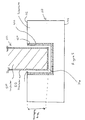
- the flexible member 220 also includes a middle portion 225 that extends between the first and second edges 223, 224.
- the middle portion 225 is raised above the top surface 212 of the substrate 210, thereby defining an inner space or chamber 226 between the top surface 212 and the inner surface 222 of the flexible member.
- the capacitor 200 is eventually sealed so that the inner space or chamber 226 is also sealed and has a fixed internal or chamber pressure (P c ).
- the middle portion 225 includes first and second arcuate or "shoulder" sections 227, 228.
- each shoulder section 227, 228 extends inwardly and upwardly from respective first and second edges 223, 224 to a middle section 229 that extends between the shoulder sections 227, 228.
- the middle section 229 is flat and parallel to the top surface 212 of the substrate 210, whereas the shoulder sections 227, 228 extend upwardly in some manner (e.g., as a result of having an arcuate shape) so that the middle section 229 is raised above the substrate 210.
- the middle portion 225 may have other shapes and that the shoulder sections 227, 228 may be arcuate or shoulder shapes or other shapes as necessary in order to raise the middle section 229 above the substrate 210.
- the flexible member 220 is made of a material that allows the middle portion 225, e.g., the middle section 229 and/or one or more shoulder sections 227, 228 depending on the capacitor 200 configuration and fluid pressure application, resulting in deformation, deflection or bending of the middle portion 225 under fluid pressure (P f ) if the fluid pressure is greater than the internal chamber pressure (Pc) (as shown in Figure 4 ).
- the flexible member 220 may be resilient to return from a deformed shape (as shown in Figure 4 ) to an initial or relaxed shape (as shown in Figure 3 ) when the external fluid pressure is less than the internal chamber pressure.
- the flexible member 220 may be composed of a material having a suitable Young's modulus of about 1 GPa to about 10 GPa, e.g., about 4 GPa.
- a suitable material for the flexible member 120 is Parylene, e.g., Parylene C, D, N, F, HT, A and AM.
- the flexible member 120 may be composed of other suitable materials that provide desired flexibility and/or resiliency attributes. Selection of flexible member 120 materials may also depend on, for example, ease of micromachining, CMOS/MEMS process compatibility and biocompatibility (e.g., USP Class VI implantable grade).
- the flexible member 220 may be made of Parylene, have a width of about 500 microns, and the shoulder sections 227, 228 may be configured so that the middle section 229 is raised above the top surface 212 of the substrate 210 by about 10 microns.
- the middle portion 225 may be moved or deflected by about 10 microns towards the substrate 210. It should be understood that these dimensions are provided as one example of how a variable capacitor 200 having a raised flexible member 220 may be implemented, and other configurations may be utilized for different applications.
- capacitor elements 232 may be in the form of fingers or plates that extend indirectly from the flexible member 220 and are arranged in a comb structure. In the illustrated embodiment, capacitor elements 232 extend directly from, or are carried by, one or more cross bars or members 234. An intermediate member 236 extends between the flexible member 220 and the cross bars or members 234. Figures 2-4 illustrate an embodiment that includes a single intermediate member 236 that connects the middle section 229 of the flexible member 220 and the cross-bar member 234. Portions of the chamber 226 are defined by the inner surface 222 of the middle section 229, cross bar members 234, the intermediate member 236 extending between the flexible member and a cross bar member 234.
- the number of intermediate members 236 is less than the number of capacitor elements 232.
- a single intermediate member 236 joins the middle section 229 and a cross bar 234 that carries a plurality of capacitor elements 232.
- This configuration advantageously provides a flexible member 220 having sufficient flexibility and advantageously provides linear or vertical movement or substantially linear or vertical movement of capacitor elements 232 within channels 216 even when the flexible member 220 is deformed.
- embodiments advantageously utilize an intermediate member 236 / cross bar 234 configuration so that capacitor elements 232 extend indirectly from the flexible member, thereby preventing the capacitor elements 232 from being pushed out at an angle when the flexible member 220 is deformed, e.g., in a bowl-like shape, by fluid pressure.
- At least one capacitor element 232 is in-line with, or within the same vertical plane defined by, the intermediate member 236, and at least one other capacitor element 232 is within a vertical plane that is offset from the vertical plane defined by the intermediate member 236.
- the middle capacitor element 232 lies within the same vertical plane defined by the intermediate member 236, and the other capacitor elements lie within different vertical planes and are parallel to the plane defined by the intermediate member 236 and the middle capacitor element 232.
- the capacitor elements 232 may be arranged so that no capacitor element 232 is in-line with or within the same vertical plane defined by the intermediate member 236, but all capacitor elements 232 are parallel to the plane defined by the intermediate member 236.
- the particular configuration utilized may depend on, e.g., the number of intermediate members 236, the number of capacitor elements 232 and the arrangement of these components.
- capacitor elements 232 are configured and have a suitable shape and size so that they may move with the flexible member 220 within channels 216, e.g., within channels 216 of a corresponding substrate 120 comb structure.
- a capacitor element 232 is a conductive material 510, such as a metal, and may be optionally coated with an insulation material 512.
- the capacitor element 232 may include a metal coating that is applied over a conductive, non-metallic material.
- a channel 216 may also include an insulative coating 520 and a conductive or metal coating 522 that is applied within the channel 216 using metallization.
- the flexible member 220 having capacitor elements 232 extending there from is used as a variable capacitor electrode, and the substrate 110 is used as a ground electrode. If the internal chamber 226 pressure is greater than the external fluid pressure, then the flexible member 220 will not be deformed or bent and will retain its original or initial shape. If the fluid pressure exceeds the chamber 226 pressure, then the middle portion 229, e.g., the middle section 225 of the flexible member 220, will be deformed or deflected by the fluid pressure.
- the flexible member 220 may be sufficiently thin (e.g., about 10 microns) so that the amount of deflection of the middle portion 229 is proportional to the difference between the external fluid pressure and the internal chamber pressure, (( ⁇ )( ⁇ )( ⁇ P)). At the same time, the position of the capacitor elements 232 extending from the flexible member 220 is changed, i.e., the capacitor elements 232 move with the moving flexible member 220.
- the effective overlapping area between interdigitated electrodes is changed which, in turn, alters the capacitance across the electrodes. More specifically, the capacitance increases as the capacitor elements 232 are moved deeper within respective channels 216 and the overlapping area of the substrate 220 and the capacitor elements 232 increases, and capacitance decreases as the capacitor elements 232 are moved to a shallower depth within the channel 216 and the overlapping area of the substrate 220 and the capacitor elements 232 decreases.
- capacitor elements 232 may assume an initial, relaxed position, generally illustrated as (0,0).
- the initial position may be the capacitor elements 232 being positioned partially within respective channels 216.
- a capacitor element 232 may be positioned outside above the channels 216, e.g., above the top surface 112 in the illustrated example.
- the initial relaxed position may depend on the variable capacitor 200 configuration, e.g., how far the flexible member 220 may be deflected or deformed and the length of the capacitor elements 232.
- Figure 7 illustrates one example in which the initial, relaxed position is a position in which distal portions of capacitor elements 232 are positioned partially inside respective channels 216.
- the flexible member 220 is in its initial, relaxed state, and the capacitor elements 232 are positioned at a first depth within the channels 216.
- This arrangement results in an initial overlapping area (A1) of the distal portions of the capacitor elements 232 and the substrate 210, and a corresponding capacitance C1.
- the flexible member 220 will bend or deflect towards the substrate 210 to a greater degree, thereby moving the capacitor elements 232 to a third, depth within the channels 216. This movement results in the overlapping area of the capacitor elements 232 and the substrate 210 to increase from A2 to A3 and a corresponding increase in capacitance from C2 to C3.
- Figure 10 illustrates how a change in capacitance may be correlated to a change in fluid pressure on the flexible member 220.
- a 0.4 pF change of capacitance corresponds to a pressure change of 1mm Hg.
- embodiments are capable of pressure measurements with 1 mm Hg sensitivity.
- the total capacitance should be sufficiently high to allow a variable capacitor 200 to be used in telemetry systems (e.g., in the system generally illustrated in Figure 1 ).
- Total capacitance may be increased by increasing the area of the capacitor elements 232 (larger electrode overlapping area), providing a larger number of capacitor elements 232, structuring the flexible member 220 so that it may be deflected to greater depths within channels 216 to increase overlapping areas, and decreasing the distance between interdigitated electrodes.
- Additional considerations for effective telemetry include having a pressure sensor with sufficiently high inductance and sufficiently high coupled capacitance in order to allow the resulting resonant frequency of the sensor circuit to lie within a reasonable detection range.
- the resonant frequency of an implantable sensor circuit should lie between 10-500 MHz for telemetry involving biomedical applications.
- microfabricated implantable pressure sensors should also have inductor elements that allow the sensor to be implantable and provide electrical characteristics (e.g. resonant frequency) suitable for use in biomedical applications and telemetry.
- Figures 11-15 illustrate different embodiments of pressure sensors having lump inductors or inductors having a fixed inductance.
- Figure 11 illustrates a lump inductor 1110 constructed in accordance with one embodiment for use in a microfabricated implantable pressure sensor 1100 includes a variable capacitor 200 (not illustrated in Figure 11 for clarity).
- Figure 12 is a perspective cross-sectional view illustrating metallic layers 1211 along two sides of the variable capacitor 200 in order to illustrate how the variable capacitor 200 and the inductor 1210 may be integrated within the sensor 1200, but it should be understood that the stacked metallic layers 1211 are arranged around the variable capacitor 200.
- the inductor 1110 is formed by metal lines 1112 that are integrated within the top surface 212 of the substrate 210 and surround the variable capacitor 200. In the illustrated embodiment, a single wire 1112 is wound in a spiral pattern around the variable capacitor 200.
- One example implementation of the inductor 1110 shown in Figure 11 may include a metallic line or element 1112 having a thickness of about 2 microns, a width of about 20 microns, and being wound to form about five overlapping sections. Overlapping metal lines 1112 may be spaced apart by about 10 microns.
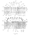
- a microfabricated pressure sensor 1200 includes an inductor 1210 that is formed as a stack of metallic layers 1211 that are fabricated using surface-micromachining methods.
- the inductor 1210 is arranged so that alternating insulative layers 1212 and metallic layers 1211 are stacked together.
- This inductor configuration may be particularly suited for configurations that required increased lump inductance and lump capacitance.
- the insulative layer 1212 may be a polymer such as Parylene or the same material that is used to form the flexible member 220. All of the metallic layers 1211 may be embedded within an insulative material 1212, or a top metallic layer 1211 may be exposed (as shown in Figure 12 ).
- the inductor 1210 may include a stack of about two to four metallic layers 1211.
- the thickness of a metallic layer 1211 may be about 2 microns
- a width of a metallic layer 1211 may be about 20 microns
- the thickness of the insulative layer 1212 between metallic layers 1211 may be about 2 microns.
- a microfabricated pressure sensor 1300 may include a variable capacitor 200 (as shown in Figures 1-10 ) and a high aspect ratio inductor 1310.
- Figure 13 is a perspective cross-sectional view illustrating the inductor 1210 elements along two sides of the variable capacitor 200 in order to illustrate how the variable capacitor 200 and the inductor 1310 may be integrated within the sensor 1300, but it should be understood that the metal lines 1311 are arranged around the variable capacitor 200.
- the inductor may include thick metal lines 1311 that fill channels 216 that are formed completely through the portions of the substrate 210.
- the metal lines 1311 may fill channels 216 formed partially through the substrate 210 depending on the desired inductance and resistance.
- the thickness of the substrate 210 may be about 500 microns
- metal lines 1311 may extend through the substrate 210 to have a depth that is also about 500 microns
- the width of the metal lines 1311 may be about 20 microns
- the metal lines 1311 may extend along the length of the substrate 210, e.g., about 3 millimeters.
- a microfabricated pressure sensor 1400 may include a variable capacitor 200 and a lump inductor 1410 in the form of an inductor sheet.
- the sensor 1400 is shown as having an inductor sheet 1410 that is coupled to metal lines 1311 of the high aspect ratio inductor 1310 shown in Figure 13 .
- the inductor sheet 1410 may be used as the sole inductor element, or in combination with other types of inductors, e.g., as shown in Figures 11 and 12 .
- Figures 14 and 15 are provided as one example of how embodiments may be implemented.
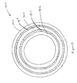
- the inductor sheet 1410 has a circular shape (when in an expanded or relaxed shape) and includes alternating metallic layers 1411 and insulative layers 1412.
- the metallic layers 1411 may be platinum, titanium and gold, or another suitable biocompatible metal or conductive materials.
- the insulative layers 1412 may be a polymer such as Parylene.
- the inductor sheet 1410 is preferably configured for implantation through a clinical gauge needle (e.g., having a 20-25 gauge size).
- the inductor sheet 1410 may be configured to assume a stressed or compressed shape when being delivered through a needle and an expanded or relaxed shape after the sensor 1400 is deployed from the needle and implanted.
- the inductor sheet 1410 may be rolled or folded while positioned within the needle and may expand to assume a circular shape (as shown in Figures 14 and 15 ) when the pressure sensor 1400 is deployed from the needle.
- Figure 16A illustrates an embodiment of a method 1600 of fabricating a micromachined pressure sensor having a variable capacitor (e.g., as shown in Figures 1-10 ) and a lump inductor (e.g., the inductor 1310 as shown in Figure 13 ). It should be understood that method steps shown in Figure 16A can be utilized and/or adapted to fabricate pressure sensors having other variable capacitors and other lump inductors (e.g., as shown in Figures 11, 12 , 14 and 15 ). For ease of explanation, reference is made to a method for fabricating the pressure sensor having a variable capacitor and lump inductor shown in Figure 13 .
- a substrate 210 such as a silicon wafer.
- the substrate 210 may have a thickness of about 500 microns.
- the substrate 210 is etched, e.g., deep reactive-ion etching (DRIE).
- DRIE deep reactive-ion etching
- the width of the channels 216 in the central portion of the substrate 210 may be about 20 microns, and the depth of the channels 216 in the central portion of the substrate 210 may be about 200 microns.
- the width of the other channels 216 formed through the substrate 210 may also be about 20 microns.
- a tissue anchor (not shown in Figure 16A ) may be created on the backside 214 of the substrate 210.
- a suitable tissue anchor is described in U.S. Publication No. 2006/0247664 , entitled "Micromachined Tissue Anchors for Securing Implants Without Sutures by E. Meng et al.
- a first insulative layer 520 (e.g., as shown in Figure 5 ) is deposited over the top surface 212 of the substrate 210.
- the insulative layer 520 may be Parylene and may have a thickness of about 2 microns.
- the first Parylene layer 520 is applied and patterned to coat surfaces that were exposed as a result of the etching at stage 1605, i.e., the inner surfaces of the open channels 216 formed partially and completely through the substrate 210
- metal electroplating is performed on the open channels 216 that were formed through the substrate 210 so that these channels 216 are filled with metal 1311 (as further illustrated in Figure 13 ). These metal-filled channels or lines 1311 will eventually form the high aspect ratio inductor 1310 that is integrated within the substrate 210.
- stage 1620 surface metallization is performed on channels 216 that were formed partially through the substrate 210, thereby forming a layer of metal 522 over the first Parylene layer 520 (as further illustrated in Figure 5 )
- a first sacrificial coating of photoresist 1626 is applied (e.g., by spin coating) over a portion of the substrate 210.
- the thickness of the first photoresist coating 1626 may be about 10 microns.
- One suitable photoresist 1626 that may be utilized with embodiments is a layer of AZ4620 type photoresist (supplied by Clariant Corp., Charlotte, NC).
- the photoresist 1626 may be hard-baked at about 120°C for smoothing of edges and degassing purposes.
- the first photoresist coating 1626 is applied over the metal-filled channels 1311 positioned between other open channels 216 formed partially through the substrate 210.
- Parylene is applied and patterned a second time to fill with Parylene open channels 216 that were previously coated with metal, and to coat the photoresist 1626 with Parylene.
- the second Parylene layer may have a thickness of about 2 microns and will eventually form capacitor elements 232 and the cross bar 234 (as further illustrated in Figures 2 and 13 ).
- a second sacrificial photoresist coating 1636 is applied and patterned over the second Parylene coating that forms capacitor elements 232 and cross bar 234 elements, over portions of the substrate 210 and over channels 216 filled with metal 1311.
- the thickness of the second photoresist coating 1636 may be about 15 microns.
- metal connections are formed on electrodes (not shown for clarity) for purposes of connecting the metal-filled channels 216 (inductor wires 1311) and capacitor elements or interdigitated electrodes.
- the third Parylene coating may have a thickness of about 5 microns and forms the flexible member 220 and an intermediate member 236 that extends between the flexible member 220 and the cross bar 234 elements formed at stage 1635.
- the third Parylene layer covers the second photoresist coating 1636, portions of the substrate 210 and metal filled channels 216.
- the third Parylene coating is applied over sections that will eventually form the variable capacitor 220 and other sections that will eventually form the lump inductor 1310.
- the backside 212 of the substrate 210 is etched, e.g., using DRIE, and at stage 1655, the first and second photoresist layers 1626, 1636 that were applied at stages 1625 and 1630 are stripped away, thereby releasing the device components.
- metal 1311 that fills the channels 216 formed through the entire substrate 210 form the high aspect ratio fixed inductor 1310 (as further illustrated in Figure 13 )
- the top electrode plates or capacitor elements 232 are joined by cross bar elements 234 and are connected to the intermediate member 236, which extends between the cross bar elements 234 and the flexible member 220 (as further illustrated in Figures 2-4 and 13 )
- the bottom electrode plates form projections or fingers 218 and corresponding channels 216 in which capacitor elements 232 move to vary capacitance.
- the inductor may be a fixed inductor (e.g., as shown in Figure 13 ), or method embodiments can be applied to fabricate a structure having a variable capacitor (as discussed above) and a variable inductor, e.g., as shown in Figures 16B .
- the variable inductor shown in Figure 16B may be formed by stage 1660 during which further etching 1660 of the silicon substrate 210 is performed to release the metal 1311 components and form a variable inductor.
- embodiments can be adapted for fabrication of various variable capacitor / lump inductor and variable capacitor / variable inductor configurations, and it should be understood that Figures 16A-B are provided to show examples of how embodiments may be implemented.
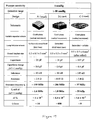
- Figure 17 is a table summarizing expected physical, electrical and microelectromechanical attributes of microfabricated pressure sensors having a variable capacitor as shown in Figures 1-10 and different lump inductors having fixed inductance as shown in Figures 12-15 . Data in Figure 17 was derived using finite element analysis and accepted electrical model calculations.
- Embodiments advantageously provide microfabricated pressure sensors having sufficiently high capacitance, inductance, resonant frequency (f r ), fr shift ( ⁇ t) and sensitivity ( ⁇ f/fr), and sufficiently low resistance.
- Figure 17 shows that the pressure sensor 1200 shown in Figure 12 has high inductance (about 40nh), the pressure sensor 1300 shown in Figure 13 low resistance (about 0.03 ohm) and a high Q factor ( ⁇ 600), and the pressure sensor 1400 shown in Figure 14 has high inductance (about 145nh) and high capacitance (about 127 pF).
- the pressure sensor 1300 including the high aspect ratio inductor 1310 has the lowest resistance ( ⁇ 0.03 ohm). Ratios of ( ⁇ F / fr) for all three pressure sensors 1200, 1300, 1400 were determined to exceed 10 -3 , indicating that sensor embodiments would be suitable for detection by an external measurement device of a telemetry system.
- Figure 17 also shows that microfabricated pressure sensors constructed according to embodiments should have sufficient sensitivity to be able to measure 1 mm Hg pressure changes, which correspond to a capacitance change of about 0.4pF, while providing for a detection range of about 1-50mmHg.
- Figure 17 also shows that microfabricated pressure sensors that include a variable capacitor and inductors according to embodiments are advantageously sufficiently small in size so that they may be implanted through a clinical gauge needle and be implanted in various parts of an eye.
- pressure sensors 1200 having the variable capacitor 200 ( Figures 2-4 ) and the inductor 1210 ( Figure 12 ) or the inductor 1310 ( Figure 13 ) have dimensions of about 0.5mm x 0.5mm 3.0 mm
- pressure sensors 1400 having the variable capacitor 200 ( Figures 2-4 ) and the inductor 1410 including a rollable sheet has dimensions of about 0.5mm x 0.5mm x 4.0mm (when in a stressed or compressed configuration).
- Other minimally invasive incisions may also be utilized if desired, e.g. incisions in the cornea that are smaller than about 3mm to allow self-healing of the cornea.
- tissue anchors may be utilized to implant sensor embodiments without the need for sutures, e.g., as described in U.S. Publication No. 2006/0247664 .
- pressure sensors may include a variable capacitor and a lump inductor, or a variable capacitor and a variable inductor.
- the dimensions and configurations of variable capacitor, lump inductor and variable inductor components are provided as examples of how embodiments may be implemented, and other dimensions and configurations may be utilized to suit pressure sensing specifications and applications.
- fabrication process parameters and steps may vary with fabrication of different capacitor and inductor configurations.
- flexible member and capacitor elements may be other materials; e.g., a biocompatible metal, and may be the same or different materials.
- Embodiments may also be utilized with variable capacitors having capacitor elements that are movable within channels formed in a substrate and with variable capacitors that are implemented without substrate channels.
- sensor devices may be implanted through corneal or scleral incisions of a suitable size. Sensor devices may also be implanted using tissue anchors or hooks. It should also be understood that embodiments may be utilized in various biomedical applications.
- microfabricated pressure sensor for passive monitoring of intraocular pressure using telemetry
- embodiments may also be used or adapted for use in other applications including, but not limited to, monitoring pressure of other bodily fluids and physiological parameters such as monitoring pressure of blood within an aneurysm, monitoring pressure of cerebrospinal fluid and monitoring pressure in other biomedical applications.
Claims (8)
- Condensateur variable (200) d'un capteur de pression implantable fabriqué à l'échelle du micromètre, comprenant :un substrat (210) définissant plusieurs canaux (216) ;un membre flexible (220) possédant un premier et un deuxième bord (223, 224) sur le substrat (210) et une portion médiane (225) s'étendant entre le premier et le deuxième bord (223, 224) et surélevée au-dessus du substrat (210) pour définir une chambre (226) entre le substrat (210) et la portion médiane (225) ; etplusieurs éléments faisant office de condensateurs (232) s'étendant à partir du membre flexible (220), lesdits plusieurs éléments faisant office de condensateurs (232) étant mobiles au sein de canaux respectifs (216) en fonction de changements de pression de fluide sur une surface externe du membre flexible (220), la capacité variant en fonction de changements intervenant dans la zone chevauchante desdits plusieurs éléments faisant office de condensateurs (232) et du substrat (210) ;caractérisé en ce qu'il comprend en outre :une barre transversale (234) supportant lesdits plusieurs éléments faisant office de condensateurs (232) ; etun membre intermédiaire (236) s'étendant entre le membre flexible (220) et la barre transversale (234), lesdits plusieurs éléments faisant office de condensateurs (232) s'étendant indirectement à partir du membre flexible (220).
- Condensateur variable (200) selon la revendication 1, dans lequel la portion médiane (225) est à même de se déformer pour passer d'une configuration exempte de tensions à une configuration déformée lorsque la pression de fluide sur la surface externe de la portion médiane dépasse une pression interne à la chambre, ce qui permet d'abaisser lesdits plusieurs éléments faisant office de condensateurs (232) plus profondément au sein des canaux respectifs (216) pour ainsi augmenter la zone de chevauchement et la capacité.
- Condensateur variable (200) selon la revendication 1, dans lequel la portion médiane (225) est résiliente pour reprendre configuration exempte de tensions à partir d'une configuration déformée lorsque la pression de fluide sur la surface externe de la portion médiane (225) est inférieure à une pression interne à la chambre, ce qui permet d'élever lesdits plusieurs éléments faisant office de condensateurs (232) moins profondément au sein des canaux respectifs (216) pour ainsi diminuer la zone de chevauchement et la capacité.
- Condensateur variable (200) selon la revendication 1, dans lequel le membre flexible (220) est constitué d'un polymère.
- Condensateur variable (200) selon la revendication 1, dans lequel lesdits plusieurs canaux (216) définissent une première structure en forme de peigne, lesdits plusieurs éléments faisant office de condensateurs définissant une deuxième structure en forme de peigne.
- Condensateur variable (200) selon la revendication 1, dans lequel la flexibilité de la portion médiane (225) varie sur la largeur de la portion médiane, une déformation non linéaire de la portion médiane (225) donnant lieu à un mouvement desdits plusieurs éléments faisant office de condensateurs (232) au sein des canaux respectifs (216) dans une direction qui est perpendiculaire à un plan défini par la surface supérieure du substrat (210).
- Condensateur variable (200) selon la revendication 1, dans lequel la chambre (226) est définie par le membre flexible (220), par la barre transversale (230) et par le membre intermédiaire (236).
- Condensateur variable (200) selon la revendication 1, dans lequel le membre intermédiaire (236) et au moins un élément faisant office de condensateur (232) sont disposés dans un plan vertical commun, et au moins un élément faisant office de condensateur (232) est disposé dans un plan vertical qui est décalé par rapport à un plan vertical défini par le membre intermédiaire (236) et parallèle audit plan.
Priority Applications (1)
| Application Number | Priority Date | Filing Date | Title |
|---|---|---|---|
| EP14171832.0A EP2786701B1 (fr) | 2006-08-29 | 2007-08-29 | Capteur de pression sans fil implantable microfabriqué destiné à être utilisé dans des applications biomédicales, et procédés de mesure de pression et d'implantation de capteur |
Applications Claiming Priority (2)
| Application Number | Priority Date | Filing Date | Title |
|---|---|---|---|
| US84111306P | 2006-08-29 | 2006-08-29 | |
| PCT/US2007/077156 WO2008027996A2 (fr) | 2006-08-29 | 2007-08-29 | Capteur de pression sans fil implantable microfabriqué destiné à être utilisé dans des applications biomédicales, et procédés de mesure de pression et d'implantation de capteur |
Related Child Applications (2)
| Application Number | Title | Priority Date | Filing Date |
|---|---|---|---|
| EP14171832.0A Division EP2786701B1 (fr) | 2006-08-29 | 2007-08-29 | Capteur de pression sans fil implantable microfabriqué destiné à être utilisé dans des applications biomédicales, et procédés de mesure de pression et d'implantation de capteur |
| EP14171832.0A Division-Into EP2786701B1 (fr) | 2006-08-29 | 2007-08-29 | Capteur de pression sans fil implantable microfabriqué destiné à être utilisé dans des applications biomédicales, et procédés de mesure de pression et d'implantation de capteur |
Publications (3)
| Publication Number | Publication Date |
|---|---|
| EP2056708A2 EP2056708A2 (fr) | 2009-05-13 |
| EP2056708A4 EP2056708A4 (fr) | 2013-04-03 |
| EP2056708B1 true EP2056708B1 (fr) | 2014-07-16 |
Family
ID=39136850
Family Applications (2)
| Application Number | Title | Priority Date | Filing Date |
|---|---|---|---|
| EP14171832.0A Not-in-force EP2786701B1 (fr) | 2006-08-29 | 2007-08-29 | Capteur de pression sans fil implantable microfabriqué destiné à être utilisé dans des applications biomédicales, et procédés de mesure de pression et d'implantation de capteur |
| EP07814555.4A Not-in-force EP2056708B1 (fr) | 2006-08-29 | 2007-08-29 | Capteur de pression sans fil implantable microfabriqué destiné à être utilisé dans des applications biomédicales, et procédés de mesure de pression et d'implantation de capteur |
Family Applications Before (1)
| Application Number | Title | Priority Date | Filing Date |
|---|---|---|---|
| EP14171832.0A Not-in-force EP2786701B1 (fr) | 2006-08-29 | 2007-08-29 | Capteur de pression sans fil implantable microfabriqué destiné à être utilisé dans des applications biomédicales, et procédés de mesure de pression et d'implantation de capteur |
Country Status (6)
| Country | Link |
|---|---|
| US (3) | US7900518B2 (fr) |
| EP (2) | EP2786701B1 (fr) |
| JP (1) | JP5307008B2 (fr) |
| ES (1) | ES2565987T3 (fr) |
| MX (1) | MX2009002193A (fr) |
| WO (1) | WO2008027996A2 (fr) |
Families Citing this family (98)
| Publication number | Priority date | Publication date | Assignee | Title |
|---|---|---|---|---|
| JP5307008B2 (ja) | 2006-08-29 | 2013-10-02 | カリフォルニア インスティテュート オブ テクノロジー | 生物医学的応用に用いられる微細加工された移植可能な無線圧力センサーおよび圧力測定ならびにセンサー移植方法 |
| US7677107B2 (en) * | 2007-07-03 | 2010-03-16 | Endotronix, Inc. | Wireless pressure sensor and method for fabricating wireless pressure sensor for integration with an implantable device |
| US7980145B2 (en) * | 2007-12-27 | 2011-07-19 | Y Point Capital, Inc | Microelectromechanical capacitive device |
| US8608632B1 (en) | 2009-07-03 | 2013-12-17 | Salutaris Medical Devices, Inc. | Methods and devices for minimally-invasive extraocular delivery of radiation and/or pharmaceutics to the posterior portion of the eye |
| US10022558B1 (en) | 2008-01-07 | 2018-07-17 | Salutaris Medical Devices, Inc. | Methods and devices for minimally-invasive delivery of radiation to the eye |
| US9056201B1 (en) | 2008-01-07 | 2015-06-16 | Salutaris Medical Devices, Inc. | Methods and devices for minimally-invasive delivery of radiation to the eye |
| EP2676701B1 (fr) | 2008-01-07 | 2016-03-30 | Salutaris Medical Devices, Inc. | Dispositifs d'administration extraoculaire à invasion minimale de rayonnement sur la partie postérieure de l'oeil |
| US8602959B1 (en) | 2010-05-21 | 2013-12-10 | Robert Park | Methods and devices for delivery of radiation to the posterior portion of the eye |
| US9873001B2 (en) | 2008-01-07 | 2018-01-23 | Salutaris Medical Devices, Inc. | Methods and devices for minimally-invasive delivery of radiation to the eye |
| CN102099078A (zh) | 2008-04-17 | 2011-06-15 | 阿勒根公司 | 可植入的连接口装置和固定系统 |
| US9023063B2 (en) | 2008-04-17 | 2015-05-05 | Apollo Endosurgery, Inc. | Implantable access port device having a safety cap |
| US8926524B2 (en) * | 2008-06-02 | 2015-01-06 | California Institute Of Technology | System, apparatus and method for biomedical wireless pressure sensing |
| DE102008033805A1 (de) * | 2008-07-18 | 2010-01-21 | Neue Magnetodyn Gmbh | System zum Erfassen von Messwerten in oder an einem Organismus und Verfahren zum Herstellen einer Komponente dieses Systems |
| JP2010075325A (ja) * | 2008-09-25 | 2010-04-08 | Fujifilm Corp | 内視鏡軟性部及び内視鏡 |
| US8069730B2 (en) * | 2008-11-14 | 2011-12-06 | Kulite Semiconductor Products, Inc. | Pressure transducer structures suitable for curved surfaces |
| USD691270S1 (en) | 2009-01-07 | 2013-10-08 | Salutaris Medical Devices, Inc. | Fixed-shape cannula for posterior delivery of radiation to an eye |
| USD691268S1 (en) | 2009-01-07 | 2013-10-08 | Salutaris Medical Devices, Inc. | Fixed-shape cannula for posterior delivery of radiation to eye |
| USD691269S1 (en) | 2009-01-07 | 2013-10-08 | Salutaris Medical Devices, Inc. | Fixed-shape cannula for posterior delivery of radiation to an eye |
| USD691267S1 (en) | 2009-01-07 | 2013-10-08 | Salutaris Medical Devices, Inc. | Fixed-shape cannula for posterior delivery of radiation to eye |
| US9222819B2 (en) | 2009-02-20 | 2015-12-29 | University Of Southern California | Tracking and controlling fluid delivery from chamber |
| US20110303016A1 (en) * | 2009-02-24 | 2011-12-15 | University Of Southern California | Flexible polymer-based encapsulated-fluid devices |
| US8506532B2 (en) * | 2009-08-26 | 2013-08-13 | Allergan, Inc. | System including access port and applicator tool |
| US8708979B2 (en) | 2009-08-26 | 2014-04-29 | Apollo Endosurgery, Inc. | Implantable coupling device |
| US8715158B2 (en) * | 2009-08-26 | 2014-05-06 | Apollo Endosurgery, Inc. | Implantable bottom exit port |
| US8257295B2 (en) | 2009-09-21 | 2012-09-04 | Alcon Research, Ltd. | Intraocular pressure sensor with external pressure compensation |
| US8212218B2 (en) * | 2009-11-30 | 2012-07-03 | International Business Machines Corporation | Dosimeter powered by passive RF absorption |
| ES2695399T3 (es) | 2009-12-30 | 2019-01-04 | Brockman Holdings Llc | Sistema, dispositivo y método para la determinación de la presión intraocular |
| US20110196195A1 (en) * | 2010-02-05 | 2011-08-11 | Allergan, Inc. | Implantable subcutaneous access port |
| US8882728B2 (en) * | 2010-02-10 | 2014-11-11 | Apollo Endosurgery, Inc. | Implantable injection port |
| US20110270021A1 (en) | 2010-04-30 | 2011-11-03 | Allergan, Inc. | Electronically enhanced access port for a fluid filled implant |
| US20110270025A1 (en) | 2010-04-30 | 2011-11-03 | Allergan, Inc. | Remotely powered remotely adjustable gastric band system |
| US8992415B2 (en) | 2010-04-30 | 2015-03-31 | Apollo Endosurgery, Inc. | Implantable device to protect tubing from puncture |
| US8397578B2 (en) | 2010-06-03 | 2013-03-19 | Medtronic, Inc. | Capacitive pressure sensor assembly |
| US9737657B2 (en) | 2010-06-03 | 2017-08-22 | Medtronic, Inc. | Implantable medical pump with pressure sensor |
| US9408555B2 (en) | 2010-06-30 | 2016-08-09 | Indiana University Research And Technology Corporation | Supersensitive linear pressure transducer |
| WO2012009377A2 (fr) | 2010-07-12 | 2012-01-19 | University Of Southern California | Substrat biocompatible destiné à faciliter les interconnexions entres les cellules souches et les tissus cibles et procédés d'implantation associés |
| EP2412305A1 (fr) * | 2010-07-30 | 2012-02-01 | Ophtimalia | Capteur passif flexible intégré dans une lentille de contact souple pour surveillance IOP |
| US20120041258A1 (en) | 2010-08-16 | 2012-02-16 | Allergan, Inc. | Implantable access port system |
| US20120065460A1 (en) | 2010-09-14 | 2012-03-15 | Greg Nitka | Implantable access port system |
| US8966990B2 (en) * | 2011-02-11 | 2015-03-03 | Purdue Research Foundation | MEMS devices exhibiting linear characteristics |
| WO2012137067A2 (fr) * | 2011-04-07 | 2012-10-11 | Oculox Technology | Dispositif et procédés de surveillance de pression intraoculaire |
| WO2012149468A2 (fr) | 2011-04-29 | 2012-11-01 | University Of Southern California | Instruments et procédés d'implantation de substrats ensemencés de cellules |
| US8877489B2 (en) | 2011-12-05 | 2014-11-04 | California Institute Of Technology | Ultrathin parylene-C semipermeable membranes for biomedical applications |
| US8821373B2 (en) | 2011-05-10 | 2014-09-02 | Apollo Endosurgery, Inc. | Directionless (orientation independent) needle injection port |
| US8801597B2 (en) | 2011-08-25 | 2014-08-12 | Apollo Endosurgery, Inc. | Implantable access port with mesh attachment rivets |
| WO2013059195A1 (fr) * | 2011-10-17 | 2013-04-25 | Elenza, Inc. | Procédés, appareil et système de déclenchement d'un dispositif ophtalmique implantable accommodatif basé sur des changements de pression intraoculaire |
| US9199069B2 (en) | 2011-10-20 | 2015-12-01 | Apollo Endosurgery, Inc. | Implantable injection port |
| US8858421B2 (en) | 2011-11-15 | 2014-10-14 | Apollo Endosurgery, Inc. | Interior needle stick guard stems for tubes |
| US9089395B2 (en) | 2011-11-16 | 2015-07-28 | Appolo Endosurgery, Inc. | Pre-loaded septum for use with an access port |
| US9248013B2 (en) | 2011-12-05 | 2016-02-02 | California Institute Of Technology | 3-Dimensional parylene scaffold cage |
| WO2013090231A1 (fr) | 2011-12-13 | 2013-06-20 | Alcon Research, Ltd. | Systèmes de drainage actifs dotés de soupapes actionnées par pression à double entrée |
| US9339187B2 (en) | 2011-12-15 | 2016-05-17 | Alcon Research, Ltd. | External pressure measurement system and method for an intraocular implant |
| WO2014043418A1 (fr) * | 2012-09-12 | 2014-03-20 | Innovative In Vivo Sensing, Llc | Dispositif de capteur de contrainte comprenant un substrat biologique, et son procédé de production |
| US9528633B2 (en) | 2012-12-17 | 2016-12-27 | Novartis Ag | MEMS check valve |
| US9295389B2 (en) | 2012-12-17 | 2016-03-29 | Novartis Ag | Systems and methods for priming an intraocular pressure sensor in an intraocular implant |
| US9572712B2 (en) | 2012-12-17 | 2017-02-21 | Novartis Ag | Osmotically actuated fluidic valve |
| US9487386B2 (en) * | 2013-01-16 | 2016-11-08 | Infineon Technologies Ag | Comb MEMS device and method of making a comb MEMS device |
| FR3001377B1 (fr) * | 2013-01-25 | 2015-01-23 | Ophtimalia | Lentille de contact a capteur passif flexible integre |
| US10016132B2 (en) * | 2013-03-07 | 2018-07-10 | The Board Of Trustees Of The Leland Stanford Junior University | Implantable micro-fluidic device for monitoring of intra-ocular pressure |
| WO2014165822A1 (fr) | 2013-04-04 | 2014-10-09 | The Arizona Board Of Regents On Behalf Of The University Of Arizona | Matériaux, systèmes, dispositifs et procédés pour le pavage et l'enrobage électropolymères endoluminaux |
| US9848775B2 (en) | 2013-05-22 | 2017-12-26 | The Board Of Trustees Of The Leland Stanford Junior University | Passive and wireless pressure sensor |
| US9962084B2 (en) * | 2013-06-15 | 2018-05-08 | Purdue Research Foundation | Wireless interstitial fluid pressure sensor |
| US9781842B2 (en) | 2013-08-05 | 2017-10-03 | California Institute Of Technology | Long-term packaging for the protection of implant electronics |
| US9226851B2 (en) | 2013-08-24 | 2016-01-05 | Novartis Ag | MEMS check valve chip and methods |
| CN104697702B (zh) * | 2013-12-04 | 2017-06-13 | 中芯国际集成电路制造(上海)有限公司 | Mems器件及其形成方法 |
| WO2015089175A1 (fr) | 2013-12-11 | 2015-06-18 | The Board Of Regents Of The University Of Texas System | Dispositifs et procédés pour mesurer des paramètres |
| US10499822B2 (en) * | 2014-05-09 | 2019-12-10 | The Royal Institution For The Advancement Of Learning / Mcgill University | Methods and systems relating to biological systems with embedded mems sensors |
| US9939331B2 (en) | 2014-05-21 | 2018-04-10 | Infineon Technologies Ag | System and method for a capacitive thermometer |
| US9322685B2 (en) * | 2014-06-30 | 2016-04-26 | The Boeing Company | MEMS-based conformal air speed sensor |
| WO2016004223A1 (fr) | 2014-07-01 | 2016-01-07 | Cao Ariel | Méthodes et dispositifs pour l'implantation de capteurs de pression intraoculaire |
| WO2016004251A1 (fr) | 2014-07-01 | 2016-01-07 | Cao Ariel | Capteurs d'implant fermés hermétiquement ayant une architecture d'empilement vertical |
| EP4032463A1 (fr) * | 2014-08-20 | 2022-07-27 | California Baptist University | Systèmes et procédés de surveillance de la santé de l' il |
| FR3025311B1 (fr) | 2014-08-26 | 2016-12-30 | Commissariat Energie Atomique | Capteur de pression d'un fluide |
| WO2016057796A1 (fr) | 2014-10-08 | 2016-04-14 | The Arizona Board Of Regents On Behalf Of The University Of Arizona | Équipements électroniques fluides |
| EP3017749A1 (fr) | 2014-11-06 | 2016-05-11 | Ophtimalia | Moyens de détection passif pour un système de surveillance d'un paramètre physiologique |
| US10845620B2 (en) | 2014-12-08 | 2020-11-24 | Aleksandr Shtukater | Smart contact lens |
| EP3277158A4 (fr) | 2015-03-31 | 2018-12-26 | California Institute of Technology | Conditionnement biocompatible pour capteurs et dispositifs électroniques implantables sur de longues durées |
| US10104478B2 (en) * | 2015-11-13 | 2018-10-16 | Infineon Technologies Ag | System and method for a perpendicular electrode transducer |
| ITUB20160704A1 (it) * | 2016-02-12 | 2017-08-12 | Valtriani Massimiliano | Dispositivo elettromedicale |
| US10353463B2 (en) | 2016-03-16 | 2019-07-16 | RaayonNova LLC | Smart contact lens with eye driven control system and method |
| USD815285S1 (en) | 2016-05-11 | 2018-04-10 | Salutaris Medical Devices, Inc. | Brachytherapy device |
| USD814638S1 (en) | 2016-05-11 | 2018-04-03 | Salutaris Medical Devices, Inc. | Brachytherapy device |
| USD814637S1 (en) | 2016-05-11 | 2018-04-03 | Salutaris Medical Devices, Inc. | Brachytherapy device |
| CN114532976A (zh) * | 2016-05-31 | 2022-05-27 | 酷拉公司 | 可植入眼压传感器和使用方法 |
| US10556791B2 (en) * | 2016-07-19 | 2020-02-11 | King Abdulaziz City For Science And Technology | CMOS compatible capacitive absolute pressure sensors |
| USD808528S1 (en) | 2016-08-31 | 2018-01-23 | Salutaris Medical Devices, Inc. | Holder for a brachytherapy device |
| USD808529S1 (en) | 2016-08-31 | 2018-01-23 | Salutaris Medical Devices, Inc. | Holder for a brachytherapy device |
| US11099405B2 (en) | 2016-09-17 | 2021-08-24 | Raayon Nova LLC | Master slave smart contact lens system |
| US11615257B2 (en) | 2017-02-24 | 2023-03-28 | Endotronix, Inc. | Method for communicating with implant devices |
| CA3053497A1 (fr) | 2017-02-24 | 2018-08-30 | Endotronix, Inc. | Ensemble lecteur capteur sans fil |
| US11122975B2 (en) | 2017-05-12 | 2021-09-21 | California Institute Of Technology | Implantable extracompartmental pressure sensor |
| US10612991B1 (en) * | 2017-08-25 | 2020-04-07 | Fluke Corporation | High dynamic range capacitive pressure sensor |
| US10694999B2 (en) * | 2017-10-13 | 2020-06-30 | Case Western Reserve University | Conductive layer formed strain gauge and method of making same |
| CN108132280B (zh) * | 2017-12-25 | 2020-11-17 | 嘉兴巨腾信息科技有限公司 | 一种用于安装气体传感器的柔性衬底 |
| US20190346692A1 (en) * | 2018-05-09 | 2019-11-14 | Johnson & Johnson Vision Care, Inc. | Electronic ophthalmic lens for measuring distance using ultrasound time-of-flight |
| US11701504B2 (en) | 2020-01-17 | 2023-07-18 | California Institute Of Technology | Implantable intracranial pressure sensor |
| WO2023018388A1 (fr) * | 2021-08-12 | 2023-02-16 | Koc Universitesi | Appareil capteur implantable sans fil et actionneur ultrasonore associé |
| US11867574B1 (en) * | 2023-05-23 | 2024-01-09 | Sanctuary Cognitive Systems Corporation | Fluidic tactile sensor |
Family Cites Families (56)
| Publication number | Priority date | Publication date | Assignee | Title |
|---|---|---|---|---|
| FR1357058A (fr) * | 1963-02-20 | 1964-04-03 | Fr D Etudes Et De Const Electr | Sonde altimétrique à capsule anéroïde pour appareils en vol |
| DE2511413A1 (de) * | 1975-03-15 | 1976-09-23 | Knorr Bremse Gmbh | Elektrischer messfuehler fuer druck, kraft oder weg |
| GB2076970A (en) * | 1980-05-19 | 1981-12-09 | Jackson Brothers London Ltd | Displacement transducers |
| US4287553A (en) * | 1980-06-06 | 1981-09-01 | The Bendix Corporation | Capacitive pressure transducer |
| US4864463A (en) * | 1988-04-19 | 1989-09-05 | Allied-Signal Inc. | Capacitive pressure sensor |
| JP2753896B2 (ja) * | 1990-11-30 | 1998-05-20 | 東信電気 株式会社 | 圧力振動検出素子 |
| US5300020A (en) * | 1991-05-31 | 1994-04-05 | Medflex Corporation | Surgically implantable device for glaucoma relief |
| DE4332057A1 (de) * | 1993-09-21 | 1995-03-30 | Siemens Ag | Integrierte mikromechanische Sensorvorrichtung und Verfahren zu deren Herstellung |
| US5479827A (en) * | 1994-10-07 | 1996-01-02 | Yamatake-Honeywell Co., Ltd. | Capacitive pressure sensor isolating electrodes from external environment |
| US5499158A (en) * | 1994-11-14 | 1996-03-12 | Texas Instruments Incorporated | Pressure transducer apparatus with monolithic body of ceramic material |
| JPH0965491A (ja) * | 1995-08-18 | 1997-03-07 | Hitachi Ltd | 電気−機械変換装置 |
| JPH10148643A (ja) * | 1996-11-19 | 1998-06-02 | Tdk Corp | 加速度センサ及びその製造方法 |
| DE19728069C1 (de) * | 1997-07-01 | 1999-02-11 | Acritec Gmbh | Vorrichtung zur Messung des Augeninnendrucks |
| US5982608A (en) * | 1998-01-13 | 1999-11-09 | Stmicroelectronics, Inc. | Semiconductor variable capacitor |
| KR100300527B1 (ko) * | 1998-09-03 | 2001-10-27 | 윤덕용 | 밀봉형무선압력측정소자및그제조방법 |
| US6312380B1 (en) | 1998-12-23 | 2001-11-06 | Radi Medical Systems Ab | Method and sensor for wireless measurement of physiological variables |
| US6579235B1 (en) | 1999-11-01 | 2003-06-17 | The Johns Hopkins University | Method for monitoring intraocular pressure using a passive intraocular pressure sensor and patient worn monitoring recorder |
| US6939299B1 (en) | 1999-12-13 | 2005-09-06 | Kurt Petersen | Implantable continuous intraocular pressure sensor |
| US6505516B1 (en) * | 2000-01-06 | 2003-01-14 | Rosemount Inc. | Capacitive pressure sensing with moving dielectric |
| US7708711B2 (en) * | 2000-04-14 | 2010-05-04 | Glaukos Corporation | Ocular implant with therapeutic agents and methods thereof |
| US6749568B2 (en) | 2000-08-21 | 2004-06-15 | Cleveland Clinic Foundation | Intraocular pressure measurement system including a sensor mounted in a contact lens |
| CA2432438C (fr) | 2001-01-09 | 2011-04-26 | Microchips, Inc. | Dispositifs flexibles a micropuces a usage ophtalmique ou autre |
| US6824521B2 (en) | 2001-01-22 | 2004-11-30 | Integrated Sensing Systems, Inc. | Sensing catheter system and method of fabrication |
| US7678065B2 (en) | 2001-05-02 | 2010-03-16 | Glaukos Corporation | Implant with intraocular pressure sensor for glaucoma treatment |
| WO2002103369A1 (fr) * | 2001-06-18 | 2002-12-27 | Honeywell International Inc. | Accelerometre mems a base de silicium de lecture de haute capacite et de petite taille |
| DE10130372B4 (de) * | 2001-06-23 | 2006-09-14 | Abb Patent Gmbh | Differenzdrucksensor |
| US6855115B2 (en) | 2002-01-22 | 2005-02-15 | Cardiomems, Inc. | Implantable wireless sensor for pressure measurement within the heart |
| JP2003299627A (ja) | 2002-04-10 | 2003-10-21 | Omron Corp | 電子血圧計 |
| JP2004048536A (ja) * | 2002-07-15 | 2004-02-12 | Matsushita Electric Ind Co Ltd | マイクロホン |
| US6890300B2 (en) | 2002-08-27 | 2005-05-10 | Board Of Trustees Of Michigan State University | Implantable microscale pressure sensor system for pressure monitoring and management |
| US7131945B2 (en) * | 2002-10-16 | 2006-11-07 | California Institute Of Technology | Optically powered and optically data-transmitting wireless intraocular pressure sensor device |
| US6945116B2 (en) | 2003-03-19 | 2005-09-20 | California Institute Of Technology | Integrated capacitive microfluidic sensors method and apparatus |
| US7841940B2 (en) * | 2003-07-14 | 2010-11-30 | Astav, Inc | Human test based on human conceptual capabilities |
| US7353711B2 (en) * | 2003-08-11 | 2008-04-08 | Analog Devices, Inc. | Capacitive sensor |
| US7725395B2 (en) * | 2003-09-19 | 2010-05-25 | Microsoft Corp. | System and method for devising a human interactive proof that determines whether a remote client is a human or a computer program |
| KR100549003B1 (ko) * | 2004-02-04 | 2006-02-02 | 삼성전자주식회사 | 넓은 튜닝 범위를 갖는 멤스 튜너블 커패시터 및 그것을제조하는 방법 |
| US7216256B2 (en) * | 2004-03-30 | 2007-05-08 | Bellsouth Intellectual Property Corporation | Methods, systems, and products for verifying integrity of web-server served content |
| US7505946B2 (en) * | 2004-03-31 | 2009-03-17 | Microsoft Corporation | High performance content alteration architecture and techniques |
| US7252006B2 (en) | 2004-06-07 | 2007-08-07 | California Institute Of Technology | Implantable mechanical pressure sensor and method of manufacturing the same |
| JP4539450B2 (ja) * | 2004-11-04 | 2010-09-08 | オムロン株式会社 | 容量型振動センサ及びその製造方法 |
| US7059195B1 (en) * | 2004-12-02 | 2006-06-13 | Honeywell International Inc. | Disposable and trimmable wireless pressure sensor for medical applications |
| US7290454B2 (en) * | 2004-12-02 | 2007-11-06 | Honeywell International Inc. | Pressure flow sensor systems and pressure flow sensors for use therein |
| US8032483B1 (en) * | 2004-12-03 | 2011-10-04 | Google Inc. | Using game responses to gather data |
| US20060247664A1 (en) | 2005-03-08 | 2006-11-02 | California Institute Of Technology | Micromachined tissue anchors for securing implants without sutures |
| US7603706B2 (en) * | 2005-06-30 | 2009-10-13 | Microsoft Corporation | System security using human authorization |
| JP4907181B2 (ja) * | 2006-01-30 | 2012-03-28 | アルプス電気株式会社 | 静電容量型圧力センサ |
| US7929805B2 (en) * | 2006-01-31 | 2011-04-19 | The Penn State Research Foundation | Image-based CAPTCHA generation system |
| US8036902B1 (en) * | 2006-06-21 | 2011-10-11 | Tellme Networks, Inc. | Audio human verification |
| JP5307008B2 (ja) | 2006-08-29 | 2013-10-02 | カリフォルニア インスティテュート オブ テクノロジー | 生物医学的応用に用いられる微細加工された移植可能な無線圧力センサーおよび圧力測定ならびにセンサー移植方法 |
| US8019127B2 (en) * | 2006-09-13 | 2011-09-13 | George Mason Intellectual Properties, Inc. | Image based turing test |
| US7827265B2 (en) * | 2007-03-23 | 2010-11-02 | Facebook, Inc. | System and method for confirming an association in a web-based social network |
| US8005197B2 (en) * | 2007-06-29 | 2011-08-23 | Avaya Inc. | Methods and apparatus for defending against telephone-based robotic attacks using contextual-based degradation |
| US7677107B2 (en) * | 2007-07-03 | 2010-03-16 | Endotronix, Inc. | Wireless pressure sensor and method for fabricating wireless pressure sensor for integration with an implantable device |
| US7917508B1 (en) * | 2007-08-31 | 2011-03-29 | Google Inc. | Image repository for human interaction proofs |
| US8032480B2 (en) * | 2007-11-02 | 2011-10-04 | Hunch Inc. | Interactive computing advice facility with learning based on user feedback |
| US7516220B1 (en) * | 2008-05-15 | 2009-04-07 | International Business Machines Corporation | Method and system for detecting and deterring robot access of web-based interfaces by using minimum expected human response time |
-
2007
- 2007-08-29 JP JP2009526897A patent/JP5307008B2/ja not_active Expired - Fee Related
- 2007-08-29 ES ES14171832.0T patent/ES2565987T3/es active Active
- 2007-08-29 EP EP14171832.0A patent/EP2786701B1/fr not_active Not-in-force
- 2007-08-29 WO PCT/US2007/077156 patent/WO2008027996A2/fr active Application Filing
- 2007-08-29 EP EP07814555.4A patent/EP2056708B1/fr not_active Not-in-force
- 2007-08-29 US US11/847,262 patent/US7900518B2/en not_active Expired - Fee Related
- 2007-08-29 MX MX2009002193A patent/MX2009002193A/es active IP Right Grant
-
2010
- 2010-08-02 US US12/848,837 patent/US8336387B2/en not_active Expired - Fee Related
-
2012
- 2012-11-19 US US13/680,762 patent/US8549925B2/en not_active Expired - Fee Related
Also Published As
| Publication number | Publication date |
|---|---|
| US20130137958A1 (en) | 2013-05-30 |
| EP2786701A3 (fr) | 2014-11-05 |
| MX2009002193A (es) | 2009-04-28 |
| WO2008027996A3 (fr) | 2008-10-09 |
| JP2010503220A (ja) | 2010-01-28 |
| ES2565987T3 (es) | 2016-04-08 |
| EP2786701B1 (fr) | 2015-12-23 |
| EP2786701A2 (fr) | 2014-10-08 |
| EP2056708A4 (fr) | 2013-04-03 |
| US7900518B2 (en) | 2011-03-08 |
| EP2056708A2 (fr) | 2009-05-13 |
| WO2008027996A2 (fr) | 2008-03-06 |
| US20100294041A1 (en) | 2010-11-25 |
| US8336387B2 (en) | 2012-12-25 |
| US20080058632A1 (en) | 2008-03-06 |
| JP5307008B2 (ja) | 2013-10-02 |
| US8549925B2 (en) | 2013-10-08 |
Similar Documents
| Publication | Publication Date | Title |
|---|---|---|
| EP2056708B1 (fr) | Capteur de pression sans fil implantable microfabriqué destiné à être utilisé dans des applications biomédicales, et procédés de mesure de pression et d'implantation de capteur | |
| Kouhani et al. | Wireless, passive strain sensor in a doughnut-shaped contact lens for continuous non-invasive self-monitoring of intraocular pressure | |
| Xue et al. | A SU-8-based microfabricated implantable inductively coupled passive RF wireless intraocular pressure sensor | |
| Chen et al. | Microfabricated implantable parylene-based wireless passive intraocular pressure sensors | |
| US6939299B1 (en) | Implantable continuous intraocular pressure sensor | |
| EP3164059B1 (fr) | Capteurs d'implant fermés hermétiquement ayant une architecture d'empilement vertical | |
| US8926524B2 (en) | System, apparatus and method for biomedical wireless pressure sensing | |
| US6749568B2 (en) | Intraocular pressure measurement system including a sensor mounted in a contact lens | |
| Chen et al. | Implantable micromechanical parylene-based pressure sensors for unpowered intraocular pressure sensing | |
| Shahiri-Tabarestani et al. | Design and simulation of high sensitive capacitive pressure sensor with slotted diaphragm | |
| CN103747720A (zh) | 表面形变传感器 | |
| Carrasco et al. | Biocompatibility and implant of a less invasive intraocular pressure sensor | |
| Katuri et al. | A surface micromachined capacitive pressure sensor for intraocular pressure measurement | |
| KR101996741B1 (ko) | 생리적 파라미터 모니터링 디바이스 | |
| Chen et al. | Implantable parylene-based wireless intraocular pressure sensor | |
| Kouhani et al. | Wireless intraocular pressure sensor using stretchable variable inductor | |
| WO2011127185A2 (fr) | Système de surveillance de la pression intraoculaire | |
| Sattayasoonthorn et al. | LCP MEMS implantable pressure sensor for Intracranial Pressure measurement | |
| Shin et al. | Development of novel implantable intraocular pressure sensors to enhance the performance in in vivo tests | |
| Shahiri-Tabarestani et al. | Design and simulation of new micro-electromechanical pressure sensor for measuring intraocular pressure | |
| Lin et al. | Feeling the pressure: A parylene-based intraocular pressure sensor | |
| Chen et al. | Implantable flexible-coiled wireless intraocular pressure sensor | |
| Xue et al. | Biocompatible polymeric wireless pressure sensor for intraocular pressure sensing application | |
| Ganji et al. | Increasing sensing distance of passive wireless IOP sensor | |
| Su et al. | Noninvasive Sensor for Continuous Intraocular Pressure Monitoring. |
Legal Events
| Date | Code | Title | Description |
|---|---|---|---|
| PUAI | Public reference made under article 153(3) epc to a published international application that has entered the european phase |
Free format text: ORIGINAL CODE: 0009012 |
|
| 17P | Request for examination filed |
Effective date: 20090311 |
|
| AK | Designated contracting states |
Kind code of ref document: A2 Designated state(s): AT BE BG CH CY CZ DE DK EE ES FI FR GB GR HU IE IS IT LI LT LU LV MC MT NL PL PT RO SE SI SK TR |
|
| AX | Request for extension of the european patent |
Extension state: AL BA HR MK RS |
|
| RIN1 | Information on inventor provided before grant (corrected) |
Inventor name: HUMAYUN, MARK S. Inventor name: TAI, YU-CHONGC Inventor name: RODGER, DAMIEN C. Inventor name: CHEN, PO-JUI |
|
| RIC1 | Information provided on ipc code assigned before grant |
Ipc: A61B 13/00 20060101ALI20090508BHEP Ipc: A61B 3/16 20060101AFI20090508BHEP |
|
| RIN1 | Information on inventor provided before grant (corrected) |
Inventor name: TAI, YU-CHONGC Inventor name: HUMAYUN, MARK S. Inventor name: RODGER, DAMIEN C. Inventor name: CHEN, PO-JUI |
|
| DAX | Request for extension of the european patent (deleted) | ||
| REG | Reference to a national code |
Ref country code: DE Ref legal event code: R079 Ref document number: 602007037678 Country of ref document: DE Free format text: PREVIOUS MAIN CLASS: A61B0003000000 Ipc: A61B0003160000 |
|
| A4 | Supplementary search report drawn up and despatched |
Effective date: 20130228 |
|
| RIC1 | Information provided on ipc code assigned before grant |
Ipc: A61B 5/03 20060101ALI20130222BHEP Ipc: A61B 5/0215 20060101ALI20130222BHEP Ipc: A61B 13/00 20060101ALI20130222BHEP Ipc: A61B 3/16 20060101AFI20130222BHEP Ipc: G01L 9/00 20060101ALI20130222BHEP |
|
| GRAP | Despatch of communication of intention to grant a patent |
Free format text: ORIGINAL CODE: EPIDOSNIGR1 |
|
| INTG | Intention to grant announced |
Effective date: 20140122 |
|
| GRAS | Grant fee paid |
Free format text: ORIGINAL CODE: EPIDOSNIGR3 |
|
| GRAA | (expected) grant |
Free format text: ORIGINAL CODE: 0009210 |
|
| AK | Designated contracting states |
Kind code of ref document: B1 Designated state(s): AT BE BG CH CY CZ DE DK EE ES FI FR GB GR HU IE IS IT LI LT LU LV MC MT NL PL PT RO SE SI SK TR |
|
| REG | Reference to a national code |
Ref country code: GB Ref legal event code: FG4D |
|
| REG | Reference to a national code |
Ref country code: CH Ref legal event code: EP |
|
| REG | Reference to a national code |
Ref country code: IE Ref legal event code: FG4D |
|
| REG | Reference to a national code |
Ref country code: AT Ref legal event code: REF Ref document number: 677038 Country of ref document: AT Kind code of ref document: T Effective date: 20140815 Ref country code: CH Ref legal event code: NV Representative=s name: DR. ALEXANDER MILLER, LL.M. RECHTSANWALT (D), CH |
|
| REG | Reference to a national code |
Ref country code: DE Ref legal event code: R096 Ref document number: 602007037678 Country of ref document: DE Effective date: 20140828 |
|
| REG | Reference to a national code |
Ref country code: NL Ref legal event code: VDEP Effective date: 20140716 |
|
| REG | Reference to a national code |
Ref country code: AT Ref legal event code: MK05 Ref document number: 677038 Country of ref document: AT Kind code of ref document: T Effective date: 20140716 |
|
| REG | Reference to a national code |
Ref country code: LT Ref legal event code: MG4D |
|
| PG25 | Lapsed in a contracting state [announced via postgrant information from national office to epo] |
Ref country code: BG Free format text: LAPSE BECAUSE OF FAILURE TO SUBMIT A TRANSLATION OF THE DESCRIPTION OR TO PAY THE FEE WITHIN THE PRESCRIBED TIME-LIMIT Effective date: 20141016 Ref country code: ES Free format text: LAPSE BECAUSE OF FAILURE TO SUBMIT A TRANSLATION OF THE DESCRIPTION OR TO PAY THE FEE WITHIN THE PRESCRIBED TIME-LIMIT Effective date: 20140716 Ref country code: SE Free format text: LAPSE BECAUSE OF FAILURE TO SUBMIT A TRANSLATION OF THE DESCRIPTION OR TO PAY THE FEE WITHIN THE PRESCRIBED TIME-LIMIT Effective date: 20140716 Ref country code: PT Free format text: LAPSE BECAUSE OF FAILURE TO SUBMIT A TRANSLATION OF THE DESCRIPTION OR TO PAY THE FEE WITHIN THE PRESCRIBED TIME-LIMIT Effective date: 20141117 Ref country code: GR Free format text: LAPSE BECAUSE OF FAILURE TO SUBMIT A TRANSLATION OF THE DESCRIPTION OR TO PAY THE FEE WITHIN THE PRESCRIBED TIME-LIMIT Effective date: 20141017 Ref country code: FI Free format text: LAPSE BECAUSE OF FAILURE TO SUBMIT A TRANSLATION OF THE DESCRIPTION OR TO PAY THE FEE WITHIN THE PRESCRIBED TIME-LIMIT Effective date: 20140716 Ref country code: LT Free format text: LAPSE BECAUSE OF FAILURE TO SUBMIT A TRANSLATION OF THE DESCRIPTION OR TO PAY THE FEE WITHIN THE PRESCRIBED TIME-LIMIT Effective date: 20140716 |
|
| PG25 | Lapsed in a contracting state [announced via postgrant information from national office to epo] |
Ref country code: PL Free format text: LAPSE BECAUSE OF FAILURE TO SUBMIT A TRANSLATION OF THE DESCRIPTION OR TO PAY THE FEE WITHIN THE PRESCRIBED TIME-LIMIT Effective date: 20140716 Ref country code: NL Free format text: LAPSE BECAUSE OF FAILURE TO SUBMIT A TRANSLATION OF THE DESCRIPTION OR TO PAY THE FEE WITHIN THE PRESCRIBED TIME-LIMIT Effective date: 20140716 Ref country code: CY Free format text: LAPSE BECAUSE OF FAILURE TO SUBMIT A TRANSLATION OF THE DESCRIPTION OR TO PAY THE FEE WITHIN THE PRESCRIBED TIME-LIMIT Effective date: 20140716 Ref country code: LV Free format text: LAPSE BECAUSE OF FAILURE TO SUBMIT A TRANSLATION OF THE DESCRIPTION OR TO PAY THE FEE WITHIN THE PRESCRIBED TIME-LIMIT Effective date: 20140716 Ref country code: IS Free format text: LAPSE BECAUSE OF FAILURE TO SUBMIT A TRANSLATION OF THE DESCRIPTION OR TO PAY THE FEE WITHIN THE PRESCRIBED TIME-LIMIT Effective date: 20141116 Ref country code: AT Free format text: LAPSE BECAUSE OF FAILURE TO SUBMIT A TRANSLATION OF THE DESCRIPTION OR TO PAY THE FEE WITHIN THE PRESCRIBED TIME-LIMIT Effective date: 20140716 |
|
| REG | Reference to a national code |
Ref country code: DE Ref legal event code: R097 Ref document number: 602007037678 Country of ref document: DE |
|
| PG25 | Lapsed in a contracting state [announced via postgrant information from national office to epo] |
Ref country code: MC Free format text: LAPSE BECAUSE OF FAILURE TO SUBMIT A TRANSLATION OF THE DESCRIPTION OR TO PAY THE FEE WITHIN THE PRESCRIBED TIME-LIMIT Effective date: 20140716 Ref country code: EE Free format text: LAPSE BECAUSE OF FAILURE TO SUBMIT A TRANSLATION OF THE DESCRIPTION OR TO PAY THE FEE WITHIN THE PRESCRIBED TIME-LIMIT Effective date: 20140716 Ref country code: SK Free format text: LAPSE BECAUSE OF FAILURE TO SUBMIT A TRANSLATION OF THE DESCRIPTION OR TO PAY THE FEE WITHIN THE PRESCRIBED TIME-LIMIT Effective date: 20140716 Ref country code: RO Free format text: LAPSE BECAUSE OF FAILURE TO SUBMIT A TRANSLATION OF THE DESCRIPTION OR TO PAY THE FEE WITHIN THE PRESCRIBED TIME-LIMIT Effective date: 20140716 Ref country code: DK Free format text: LAPSE BECAUSE OF FAILURE TO SUBMIT A TRANSLATION OF THE DESCRIPTION OR TO PAY THE FEE WITHIN THE PRESCRIBED TIME-LIMIT Effective date: 20140716 Ref country code: CZ Free format text: LAPSE BECAUSE OF FAILURE TO SUBMIT A TRANSLATION OF THE DESCRIPTION OR TO PAY THE FEE WITHIN THE PRESCRIBED TIME-LIMIT Effective date: 20140716 Ref country code: BE Free format text: LAPSE BECAUSE OF NON-PAYMENT OF DUE FEES Effective date: 20140831 |
|
| REG | Reference to a national code |
Ref country code: IE Ref legal event code: MM4A |
|
| PLBE | No opposition filed within time limit |
Free format text: ORIGINAL CODE: 0009261 |
|
| STAA | Information on the status of an ep patent application or granted ep patent |
Free format text: STATUS: NO OPPOSITION FILED WITHIN TIME LIMIT |
|
| 26N | No opposition filed |
Effective date: 20150417 |
|
| PG25 | Lapsed in a contracting state [announced via postgrant information from national office to epo] |
Ref country code: IE Free format text: LAPSE BECAUSE OF NON-PAYMENT OF DUE FEES Effective date: 20140829 |
|
| PG25 | Lapsed in a contracting state [announced via postgrant information from national office to epo] |
Ref country code: SI Free format text: LAPSE BECAUSE OF FAILURE TO SUBMIT A TRANSLATION OF THE DESCRIPTION OR TO PAY THE FEE WITHIN THE PRESCRIBED TIME-LIMIT Effective date: 20140716 |
|
| PG25 | Lapsed in a contracting state [announced via postgrant information from national office to epo] |
Ref country code: MT Free format text: LAPSE BECAUSE OF FAILURE TO SUBMIT A TRANSLATION OF THE DESCRIPTION OR TO PAY THE FEE WITHIN THE PRESCRIBED TIME-LIMIT Effective date: 20140716 |
|
| PG25 | Lapsed in a contracting state [announced via postgrant information from national office to epo] |
Ref country code: LU Free format text: LAPSE BECAUSE OF NON-PAYMENT OF DUE FEES Effective date: 20140829 Ref country code: HU Free format text: LAPSE BECAUSE OF FAILURE TO SUBMIT A TRANSLATION OF THE DESCRIPTION OR TO PAY THE FEE WITHIN THE PRESCRIBED TIME-LIMIT; INVALID AB INITIO Effective date: 20070829 Ref country code: BE Free format text: LAPSE BECAUSE OF FAILURE TO SUBMIT A TRANSLATION OF THE DESCRIPTION OR TO PAY THE FEE WITHIN THE PRESCRIBED TIME-LIMIT Effective date: 20140716 Ref country code: TR Free format text: LAPSE BECAUSE OF FAILURE TO SUBMIT A TRANSLATION OF THE DESCRIPTION OR TO PAY THE FEE WITHIN THE PRESCRIBED TIME-LIMIT Effective date: 20140716 |
|
| REG | Reference to a national code |
Ref country code: FR Ref legal event code: PLFP Year of fee payment: 10 |
|
| PGFP | Annual fee paid to national office [announced via postgrant information from national office to epo] |
Ref country code: DE Payment date: 20160822 Year of fee payment: 10 Ref country code: IT Payment date: 20160825 Year of fee payment: 10 Ref country code: GB Payment date: 20160819 Year of fee payment: 10 Ref country code: CH Payment date: 20160819 Year of fee payment: 10 |
|
| PGFP | Annual fee paid to national office [announced via postgrant information from national office to epo] |
Ref country code: FR Payment date: 20160822 Year of fee payment: 10 |
|
| REG | Reference to a national code |
Ref country code: DE Ref legal event code: R119 Ref document number: 602007037678 Country of ref document: DE |
|
| REG | Reference to a national code |
Ref country code: CH Ref legal event code: PL |
|
| GBPC | Gb: european patent ceased through non-payment of renewal fee |
Effective date: 20170829 |
|
| PG25 | Lapsed in a contracting state [announced via postgrant information from national office to epo] |
Ref country code: CH Free format text: LAPSE BECAUSE OF NON-PAYMENT OF DUE FEES Effective date: 20170831 Ref country code: LI Free format text: LAPSE BECAUSE OF NON-PAYMENT OF DUE FEES Effective date: 20170831 |
|
| REG | Reference to a national code |
Ref country code: FR Ref legal event code: ST Effective date: 20180430 |
|
| PG25 | Lapsed in a contracting state [announced via postgrant information from national office to epo] |
Ref country code: DE Free format text: LAPSE BECAUSE OF NON-PAYMENT OF DUE FEES Effective date: 20180301 Ref country code: GB Free format text: LAPSE BECAUSE OF NON-PAYMENT OF DUE FEES Effective date: 20170829 |
|
| PG25 | Lapsed in a contracting state [announced via postgrant information from national office to epo] |
Ref country code: IT Free format text: LAPSE BECAUSE OF NON-PAYMENT OF DUE FEES Effective date: 20170829 Ref country code: FR Free format text: LAPSE BECAUSE OF NON-PAYMENT OF DUE FEES Effective date: 20170831 |