EP2056308A1 - Electroaimant de levage - Google Patents
Electroaimant de levage Download PDFInfo
- Publication number
- EP2056308A1 EP2056308A1 EP08018926A EP08018926A EP2056308A1 EP 2056308 A1 EP2056308 A1 EP 2056308A1 EP 08018926 A EP08018926 A EP 08018926A EP 08018926 A EP08018926 A EP 08018926A EP 2056308 A1 EP2056308 A1 EP 2056308A1
- Authority
- EP
- European Patent Office
- Prior art keywords
- lifting magnet
- magnet according
- magnetically conductive
- iron
- armature
- Prior art date
- Legal status (The legal status is an assumption and is not a legal conclusion. Google has not performed a legal analysis and makes no representation as to the accuracy of the status listed.)
- Granted
Links
Images


Classifications
-
- H—ELECTRICITY
- H01—ELECTRIC ELEMENTS
- H01F—MAGNETS; INDUCTANCES; TRANSFORMERS; SELECTION OF MATERIALS FOR THEIR MAGNETIC PROPERTIES
- H01F7/00—Magnets
- H01F7/06—Electromagnets; Actuators including electromagnets
- H01F7/08—Electromagnets; Actuators including electromagnets with armatures
- H01F7/081—Magnetic constructions
-
- H—ELECTRICITY
- H01—ELECTRIC ELEMENTS
- H01F—MAGNETS; INDUCTANCES; TRANSFORMERS; SELECTION OF MATERIALS FOR THEIR MAGNETIC PROPERTIES
- H01F7/00—Magnets
- H01F7/06—Electromagnets; Actuators including electromagnets
- H01F7/08—Electromagnets; Actuators including electromagnets with armatures
- H01F7/16—Rectilinearly-movable armatures
- H01F7/1607—Armatures entering the winding
Definitions
- the invention relates to a lifting magnet, comprising a cup-shaped magnetic body made of solid iron, a magnet armature and at least one exciting coil.
- Parasitic regions are formed by magnetically non-conductive media, such as air, gases, or non-conductive solids, such as plastic, cardboard, or the like, integrated into a solenoid.
- the parasitic areas created by such media / solids result in less overall magnetic flux through the iron loop of the electromagnetic system. Frequently, such parasitic areas can not be avoided due to the production, in particular if prefabricated starting materials are used in the production of the magnets, in particular lifting magnets, which lead to gaps or cavities between the individual components.
- the invention is based on a in the DE 10 2004 023 905 A1 described, referred to as cup magnets lifting magnet, in which the substantial magnetic flux passes through an iron circle, which consists of a cup-shaped yoke with integrated armature counterpart and an anchor.
- the magnetic flux is weakened in conventional electromagnetic actuators in the form of solenoids substantially by the unavoidable air gaps, so that it is endeavored to reduce the size of the air gaps to a minimum in order to maximize the magnetic To get river.
- an armature guide tube is centrally inserted into the excitation coil, which is at least partially formed of a magnetically conductive material, wherein the permeability of the armature guide tube is at least partially smaller than the permeability of the cup-shaped yoke, the immovable armature counterpart and the movable armature.
- the starting point is a tube which has previously been homogeneously magnetically well-conducting and which must be subjected to a heat treatment followed by rapid (shock) cooling.
- the coil yoke consists of a potting compound with magnetic properties in which the excitation coil is embedded.
- the potting compound is preferably made of epoxy resin or other plastic, in the magnetic particles or fillers, such as iron filings, are evenly distributed. Such a potting compound results in deteriorated efficiency as compared with a pot-type solid iron yoke.
- the invention has for its object to take measures to optimize solenoids by avoiding the losses resulting from "parasitic" areas or at least largely reduced.
- the invention provides that these parasitic areas are filled or replaced completely or at least partially by magnetically conductive materials depending on the technical feasibility and without affecting the required electrical insulation and protection.
- the magnetically conductive materials can be both in solid form, such as in the form of iron powder (iron is hereinafter always synonymous with magnetically conductive materials), ideally with very small particle sizes below 5 microns (which allows filling of the parasitic regions to approximately 100% ), massive iron sheets, iron filings or the like, as well as in liquid form, such as magnetorheological fluids or ferrofluids.
- the aggregate state of the potting compound increases with the solids content in the potting compound of a low viscosity at e.g. 50 vol .-% steadily and is similar to just under 95 vol .-% of a paste.
- the concentration of the iron particles in the potting compound therefore depends on the one hand on the initial viscosity (carrier medium without mixed iron particles), (the lower the initial viscosity of the carrier medium, the more solids can be mixed) as well as on the individual application area by estimating whether the magnetic potting compound still has to be independently flowable, or whether it is also used in the form of a paste with high viscosity [but also a high iron content] by pressing into the air gap.
- An advantageous possibility of reducing the magnetic resistances in the parasitic regions is the use of a magnetically highly conductive paste of, for example, a mixture of oil as a carrier fluid and iron powder in a high concentration to make the resulting paste homogeneous magnetic conductive by intensive mixing.
- this paste does not cure, but in some applications is more suitable than a potting compound that hardens after filling the parasitic areas.
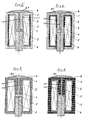
- the in FIG. 1 shown lifting magnet consists of a substantially cup-shaped magnetic body (1) made of solid iron, a Magneterregerspule 3 and a movable armature 6 in the axial direction, as part of the magnetic body 1 is an axially aligned armature 3 armature counterpart 1.1 also made of solid iron. Between the armature counterpart 1.1 and the armature 6 is a bridge 4 made of non-magnetic, ie non-magnetic material. The bridge 4 forms a generally tubular guide element for the armature 6 in the working air gap 5. For pressure equalization, the armature counterpart 1.1 is provided in each case with a connected to the working air gap 5 pressure equalization hole 1.2.
- FIGS. 2 to 11 represented elements representing the representation of FIG. 1 correspond, have the same reference numerals.
- the known solenoid according to FIG. 1 contains parasitic regions 2 in the form of air gaps and / or antimagnetic substances between the iron circuit 1, 11 and 6 and the exciter coil. 3
- the in FIG. 2 Lifting magnet shown consists of a solid iron cup-shaped magnetic body 1 including the armature counterpart 1.1, the armature 6 and the excitation coil 3, which is wound on a non-magnetic coil carrier 7, which is also effective as a bridge between the armature counterpart 1.1 and the movable armature 6.
- the according to FIG. 1 existing air gaps are thus eliminated by the bobbin 7 and the filling 9.
- FIG. 3 Lifting magnet shown consists of a cup-shaped magnetic body 1 including armature counterpart 1.1, the armature 6, the excitation coil 3 and a bridge 4.
- the according to FIG. 1 existing air gaps around the exciter coil 3, that is, the parasitic regions take a filling 9 of magnetically conductive material.
- the in FIG. 4 Lifting magnet shown consists of a static magnetic body 1 including armature counterpart 1.1, an armature 6, an excitation coil 3 and a bridge 4.
- the adjoining the working air gap 5 pressure equalization hole 1.2 opens into a
- the working air gap 5, the pressure equalization bore 1.2 and the pressure equalization chamber 8.1 contain a filling of magnetically conductive material, such as a ferrofluid or a magnetorheological fluid with optionally mixed iron powder or a magnetically conductive paste.
- the solid iron body 1 consisting of solid iron is designed so that parasitic areas, for example in the form of air gaps, are substantially absent, except for the working air gap 5 between the armature 6 and the armature core counterpart 1.1, which according to the embodiment of FIG. 5 is connected via the pressure equalization hole 1.2 to a sealed by a membrane 8 pressure equalization chamber 8.1.
- the inherently parasitic regions of the working air gap 5, the bore 1.2 and the pressure equalization chamber 8.1 contain a filling of magnetically conductive material.
- Solenoid 1 including armature counterpart 1.1, both consisting for example of a magnetically conductive Vergusskapselung, an armature 6 and a coil carrier 7.
- armature counterpart 1.1 both consisting for example of a magnetically conductive Vergusskapselung, an armature 6 and a coil carrier 7.
- the bore 1.2 1.2 in the armature counterpart 1.1 and Pressure Compensating Chamber 8.1 receives a flowable filling of magnetically conductive material.
- the solenoid according to FIG. 9 is made of solid iron, static magnetic body 11 is reduced to a cover 11.2 and the dynamic armature 6 opposite armature counterpart 11.1, which has a working air gap 5 with the pressure equalization chamber 8.1 connecting bore 11.12; the rooms 5, 8.1 and 11.12 take up a magnetically conductive, flowable filling.
- the field coil 3 is wound onto a coil carrier 7 and embedded in a parasitic areas excluding pot 12 of magnetically conductive material, for example, preferably in the form of a potting compound with admixed iron solids, wherein the rigid potting compound is formed by curing a suitable fluid.
- FIG. 10 is the existing solid iron, static magnetic body 11 on a dynamic magnetic core or armature 6 opposite magnetic core counterpart 11.1 and a lid 11.2 reduced.
- the excitation coil 3 is wound onto a bobbin 7 and according to the present invention of a parasitic areas excluding pot 12 according to FIG. 9 surrounded by magnetically conductive material. It lacks here a pressure equalization chamber and the filling of the working air gap 5 and the bore 11.1 with magnetically conductive material.
- the static magnetic body 11 consisting of solid iron is reduced to a cover 11.2, an armature counterpart 11.1 and a bottom section 11.3.
- the wound on a bobbin 7 exciter coil 3 is surrounded by a cylinder 13 of magnetically conductive material, preferably in the form of a potting compound with admixed iron solids, said rigid potting compound is formed by curing a suitable fluid.
- the magnetic efficiency considered here is independent of the switch-on time.
- the magnetic efficiency is defined as the quotient of the mechanically usable energy released in the stationary case to the ideally converted final energy.
- the magnetic efficiency also depends in particular on the size of the magnet system; For example, very small magnet systems usually have lower magnetic efficiencies than larger magnet systems, but this is independent of the actual optimization.
- a magnetic efficiency of about 60% could be measured without application of the principle according to the invention, ie without optimization in the sense of the present invention.
- the magnetic efficiency was 70%, i.
- improved by 10 percentage points which corresponds to an efficiency improvement in the range of 16 to 17%.
Landscapes
- Physics & Mathematics (AREA)
- Electromagnetism (AREA)
- Engineering & Computer Science (AREA)
- Power Engineering (AREA)
- Soft Magnetic Materials (AREA)
- Electromagnets (AREA)
Applications Claiming Priority (1)
| Application Number | Priority Date | Filing Date | Title |
|---|---|---|---|
| DE200710053005 DE102007053005A1 (de) | 2007-11-05 | 2007-11-05 | Hubmagnet sowie Verfahren zur Verbesserung des Wirkungsgrades von Hubmagneten |
Publications (2)
| Publication Number | Publication Date |
|---|---|
| EP2056308A1 true EP2056308A1 (fr) | 2009-05-06 |
| EP2056308B1 EP2056308B1 (fr) | 2013-09-18 |
Family
ID=40229763
Family Applications (1)
| Application Number | Title | Priority Date | Filing Date |
|---|---|---|---|
| EP20080018926 Not-in-force EP2056308B1 (fr) | 2007-11-05 | 2008-10-30 | Electroaimant de levage |
Country Status (2)
| Country | Link |
|---|---|
| EP (1) | EP2056308B1 (fr) |
| DE (1) | DE102007053005A1 (fr) |
Families Citing this family (1)
| Publication number | Priority date | Publication date | Assignee | Title |
|---|---|---|---|---|
| DE102011006071A1 (de) | 2011-03-24 | 2012-09-27 | Ina - Drives & Mechatronics Gmbh & Co. Ohg | Antriebseinrichtung für ein Ventil, Ventil zur Steuerung eines Gas- und/oder Flüssigkeitsstroms |
Citations (3)
| Publication number | Priority date | Publication date | Assignee | Title |
|---|---|---|---|---|
| EP0052177A1 (fr) | 1980-11-15 | 1982-05-26 | WABCO Westinghouse Fahrzeugbremsen GmbH | Electrovanne |
| DE10139447A1 (de) | 2001-08-10 | 2003-02-20 | Conti Temic Microelectronic | Spulenaufbau |
| DE102004023905A1 (de) | 2004-05-13 | 2005-12-22 | Bürkert Werke GmbH & Co. KG | Elektromagnetische Betätigungseinrichtung |
Family Cites Families (3)
| Publication number | Priority date | Publication date | Assignee | Title |
|---|---|---|---|---|
| DE3239345A1 (de) * | 1982-10-23 | 1984-04-26 | bso Steuerungstechnik GmbH, 6603 Sulzbach | Betaetigungsmagnet |
| US5955394A (en) * | 1996-08-16 | 1999-09-21 | Mobile Process Technology, Co. | Recovery process for oxidation catalyst in the manufacture of aromatic carboxylic acids |
| DE19914020C1 (de) * | 1999-03-19 | 2000-08-31 | Siemens Ag | Verfahren und Einrichtung zur Reduzierung der Geräuschemission an Wickelgütern |
-
2007
- 2007-11-05 DE DE200710053005 patent/DE102007053005A1/de not_active Withdrawn
-
2008
- 2008-10-30 EP EP20080018926 patent/EP2056308B1/fr not_active Not-in-force
Patent Citations (3)
| Publication number | Priority date | Publication date | Assignee | Title |
|---|---|---|---|---|
| EP0052177A1 (fr) | 1980-11-15 | 1982-05-26 | WABCO Westinghouse Fahrzeugbremsen GmbH | Electrovanne |
| DE10139447A1 (de) | 2001-08-10 | 2003-02-20 | Conti Temic Microelectronic | Spulenaufbau |
| DE102004023905A1 (de) | 2004-05-13 | 2005-12-22 | Bürkert Werke GmbH & Co. KG | Elektromagnetische Betätigungseinrichtung |
Also Published As
| Publication number | Publication date |
|---|---|
| DE102007053005A1 (de) | 2009-05-07 |
| EP2056308B1 (fr) | 2013-09-18 |
Similar Documents
| Publication | Publication Date | Title |
|---|---|---|
| EP2463869B2 (fr) | Composant inductif doté de propriétés de noyau améliorées | |
| EP2238601B1 (fr) | Self de choc et procede de fabrication d'une unite de noyau pour une self de choc | |
| DE3401598A1 (de) | Lineares stellglied mit hybrid-aufbau | |
| DE102009053965B4 (de) | Mit einer Vergussmasse vergossene Gradientenspule | |
| EP3494632B1 (fr) | Composant moteur, élément primaire et moteur linéaire | |
| DE1935929A1 (de) | Elektrische Vorrichtung | |
| DE112015003006T5 (de) | Kernelement, Drossel und Verfahren zum Herstellen des Kernelements | |
| DE3005573A1 (de) | Dauermagnet | |
| DE3011079A1 (de) | Verfahren zur herstellung eines magnetankers geteilten aufbaus und anker nach diesem verfahren | |
| DE102015101230A1 (de) | Drosselspule | |
| DE102013007563A1 (de) | Rotor für eine elektrische Maschine | |
| DE102018116323A1 (de) | Dreiphasige Drossel | |
| DE102013102400B4 (de) | Elektromagnetische Stellvorrichtung und Kombination von elektromagnetischer Stellvorrichtung und Motorspindel | |
| DE202005008757U1 (de) | Transformator | |
| DE102007054917A1 (de) | Verfahren zur Verbesserung des Wirkungsgrades von elektromotorischen Vorrichtungen sowie unter Anwendung dieses Verfahrens hergestellte elektromagnetische Vorrichtungen | |
| DE102006052629B4 (de) | Magnetventil | |
| EP2056308A1 (fr) | Electroaimant de levage | |
| DE202007015492U1 (de) | Hubmagnet | |
| DE102011007334A1 (de) | Flüssigkeitsgekühlte induktive Komponente | |
| EP2561520B1 (fr) | Élément inductif aux propriétés variables et son procédé de réglage | |
| EP1501106B1 (fr) | Noyau en ferrite pour inductance | |
| DE102013111079B4 (de) | Impulsmagnetventil | |
| DE2364350A1 (de) | Elektro-hydraulischer servo-verteiler | |
| DE102013208058B4 (de) | Magnetisch vorgespannte Drossel | |
| DE3043274A1 (de) | Magnetventil |
Legal Events
| Date | Code | Title | Description |
|---|---|---|---|
| PUAI | Public reference made under article 153(3) epc to a published international application that has entered the european phase |
Free format text: ORIGINAL CODE: 0009012 |
|
| AK | Designated contracting states |
Kind code of ref document: A1 Designated state(s): AT BE BG CH CY CZ DE DK EE ES FI FR GB GR HR HU IE IS IT LI LT LU LV MC MT NL NO PL PT RO SE SI SK TR |
|
| AX | Request for extension of the european patent |
Extension state: AL BA MK RS |
|
| 17P | Request for examination filed |
Effective date: 20091103 |
|
| AKX | Designation fees paid |
Designated state(s): AT BE BG CH CY CZ DE DK EE ES FI FR GB GR HR HU IE IS IT LI LT LU LV MC MT NL NO PL PT RO SE SI SK TR |
|
| GRAP | Despatch of communication of intention to grant a patent |
Free format text: ORIGINAL CODE: EPIDOSNIGR1 |
|
| 17Q | First examination report despatched |
Effective date: 20130118 |
|
| INTG | Intention to grant announced |
Effective date: 20130411 |
|
| GRAS | Grant fee paid |
Free format text: ORIGINAL CODE: EPIDOSNIGR3 |
|
| GRAA | (expected) grant |
Free format text: ORIGINAL CODE: 0009210 |
|
| AK | Designated contracting states |
Kind code of ref document: B1 Designated state(s): AT BE BG CH CY CZ DE DK EE ES FI FR GB GR HR HU IE IS IT LI LT LU LV MC MT NL NO PL PT RO SE SI SK TR |
|
| REG | Reference to a national code |
Ref country code: GB Ref legal event code: FG4D Free format text: NOT ENGLISH |
|
| REG | Reference to a national code |
Ref country code: CH Ref legal event code: EP |
|
| REG | Reference to a national code |
Ref country code: IE Ref legal event code: FG4D Free format text: LANGUAGE OF EP DOCUMENT: GERMAN |
|
| REG | Reference to a national code |
Ref country code: AT Ref legal event code: REF Ref document number: 633161 Country of ref document: AT Kind code of ref document: T Effective date: 20131015 |
|
| REG | Reference to a national code |
Ref country code: DE Ref legal event code: R096 Ref document number: 502008010670 Country of ref document: DE Effective date: 20131114 |
|
| REG | Reference to a national code |
Ref country code: NL Ref legal event code: T3 |
|
| PG25 | Lapsed in a contracting state [announced via postgrant information from national office to epo] |
Ref country code: LT Free format text: LAPSE BECAUSE OF FAILURE TO SUBMIT A TRANSLATION OF THE DESCRIPTION OR TO PAY THE FEE WITHIN THE PRESCRIBED TIME-LIMIT Effective date: 20130918 Ref country code: NO Free format text: LAPSE BECAUSE OF FAILURE TO SUBMIT A TRANSLATION OF THE DESCRIPTION OR TO PAY THE FEE WITHIN THE PRESCRIBED TIME-LIMIT Effective date: 20131218 Ref country code: CY Free format text: LAPSE BECAUSE OF FAILURE TO SUBMIT A TRANSLATION OF THE DESCRIPTION OR TO PAY THE FEE WITHIN THE PRESCRIBED TIME-LIMIT Effective date: 20130731 Ref country code: HR Free format text: LAPSE BECAUSE OF FAILURE TO SUBMIT A TRANSLATION OF THE DESCRIPTION OR TO PAY THE FEE WITHIN THE PRESCRIBED TIME-LIMIT Effective date: 20130918 Ref country code: SE Free format text: LAPSE BECAUSE OF FAILURE TO SUBMIT A TRANSLATION OF THE DESCRIPTION OR TO PAY THE FEE WITHIN THE PRESCRIBED TIME-LIMIT Effective date: 20130918 |
|
| REG | Reference to a national code |
Ref country code: LT Ref legal event code: MG4D |
|
| PG25 | Lapsed in a contracting state [announced via postgrant information from national office to epo] |
Ref country code: LV Free format text: LAPSE BECAUSE OF FAILURE TO SUBMIT A TRANSLATION OF THE DESCRIPTION OR TO PAY THE FEE WITHIN THE PRESCRIBED TIME-LIMIT Effective date: 20130918 Ref country code: GR Free format text: LAPSE BECAUSE OF FAILURE TO SUBMIT A TRANSLATION OF THE DESCRIPTION OR TO PAY THE FEE WITHIN THE PRESCRIBED TIME-LIMIT Effective date: 20131219 Ref country code: ES Free format text: LAPSE BECAUSE OF FAILURE TO SUBMIT A TRANSLATION OF THE DESCRIPTION OR TO PAY THE FEE WITHIN THE PRESCRIBED TIME-LIMIT Effective date: 20130918 Ref country code: SI Free format text: LAPSE BECAUSE OF FAILURE TO SUBMIT A TRANSLATION OF THE DESCRIPTION OR TO PAY THE FEE WITHIN THE PRESCRIBED TIME-LIMIT Effective date: 20130918 Ref country code: FI Free format text: LAPSE BECAUSE OF FAILURE TO SUBMIT A TRANSLATION OF THE DESCRIPTION OR TO PAY THE FEE WITHIN THE PRESCRIBED TIME-LIMIT Effective date: 20130918 |
|
| PG25 | Lapsed in a contracting state [announced via postgrant information from national office to epo] |
Ref country code: CY Free format text: LAPSE BECAUSE OF FAILURE TO SUBMIT A TRANSLATION OF THE DESCRIPTION OR TO PAY THE FEE WITHIN THE PRESCRIBED TIME-LIMIT Effective date: 20130918 |
|
| BERE | Be: lapsed |
Owner name: UNI-GERATE E. MANGELMANN ELEKTROTECHNISCHE FABRIK Effective date: 20131031 |
|
| PG25 | Lapsed in a contracting state [announced via postgrant information from national office to epo] |
Ref country code: SK Free format text: LAPSE BECAUSE OF FAILURE TO SUBMIT A TRANSLATION OF THE DESCRIPTION OR TO PAY THE FEE WITHIN THE PRESCRIBED TIME-LIMIT Effective date: 20130918 Ref country code: IS Free format text: LAPSE BECAUSE OF FAILURE TO SUBMIT A TRANSLATION OF THE DESCRIPTION OR TO PAY THE FEE WITHIN THE PRESCRIBED TIME-LIMIT Effective date: 20140118 Ref country code: CZ Free format text: LAPSE BECAUSE OF FAILURE TO SUBMIT A TRANSLATION OF THE DESCRIPTION OR TO PAY THE FEE WITHIN THE PRESCRIBED TIME-LIMIT Effective date: 20130918 Ref country code: RO Free format text: LAPSE BECAUSE OF FAILURE TO SUBMIT A TRANSLATION OF THE DESCRIPTION OR TO PAY THE FEE WITHIN THE PRESCRIBED TIME-LIMIT Effective date: 20130918 Ref country code: EE Free format text: LAPSE BECAUSE OF FAILURE TO SUBMIT A TRANSLATION OF THE DESCRIPTION OR TO PAY THE FEE WITHIN THE PRESCRIBED TIME-LIMIT Effective date: 20130918 |
|
| PG25 | Lapsed in a contracting state [announced via postgrant information from national office to epo] |
Ref country code: PL Free format text: LAPSE BECAUSE OF FAILURE TO SUBMIT A TRANSLATION OF THE DESCRIPTION OR TO PAY THE FEE WITHIN THE PRESCRIBED TIME-LIMIT Effective date: 20130918 |
|
| REG | Reference to a national code |
Ref country code: CH Ref legal event code: PL |
|
| REG | Reference to a national code |
Ref country code: DE Ref legal event code: R097 Ref document number: 502008010670 Country of ref document: DE |
|
| PG25 | Lapsed in a contracting state [announced via postgrant information from national office to epo] |
Ref country code: MC Free format text: LAPSE BECAUSE OF FAILURE TO SUBMIT A TRANSLATION OF THE DESCRIPTION OR TO PAY THE FEE WITHIN THE PRESCRIBED TIME-LIMIT Effective date: 20130918 Ref country code: PT Free format text: LAPSE BECAUSE OF FAILURE TO SUBMIT A TRANSLATION OF THE DESCRIPTION OR TO PAY THE FEE WITHIN THE PRESCRIBED TIME-LIMIT Effective date: 20140120 |
|
| PLBE | No opposition filed within time limit |
Free format text: ORIGINAL CODE: 0009261 |
|
| STAA | Information on the status of an ep patent application or granted ep patent |
Free format text: STATUS: NO OPPOSITION FILED WITHIN TIME LIMIT |
|
| REG | Reference to a national code |
Ref country code: IE Ref legal event code: MM4A |
|
| PG25 | Lapsed in a contracting state [announced via postgrant information from national office to epo] |
Ref country code: LI Free format text: LAPSE BECAUSE OF NON-PAYMENT OF DUE FEES Effective date: 20131031 Ref country code: CH Free format text: LAPSE BECAUSE OF NON-PAYMENT OF DUE FEES Effective date: 20131031 |
|
| 26N | No opposition filed |
Effective date: 20140619 |
|
| REG | Reference to a national code |
Ref country code: DE Ref legal event code: R097 Ref document number: 502008010670 Country of ref document: DE Effective date: 20140619 |
|
| PG25 | Lapsed in a contracting state [announced via postgrant information from national office to epo] |
Ref country code: DK Free format text: LAPSE BECAUSE OF FAILURE TO SUBMIT A TRANSLATION OF THE DESCRIPTION OR TO PAY THE FEE WITHIN THE PRESCRIBED TIME-LIMIT Effective date: 20130918 Ref country code: BE Free format text: LAPSE BECAUSE OF NON-PAYMENT OF DUE FEES Effective date: 20131031 |
|
| PG25 | Lapsed in a contracting state [announced via postgrant information from national office to epo] |
Ref country code: IE Free format text: LAPSE BECAUSE OF NON-PAYMENT OF DUE FEES Effective date: 20131030 |
|
| REG | Reference to a national code |
Ref country code: AT Ref legal event code: MM01 Ref document number: 633161 Country of ref document: AT Kind code of ref document: T Effective date: 20131030 |
|
| PGFP | Annual fee paid to national office [announced via postgrant information from national office to epo] |
Ref country code: DE Payment date: 20141222 Year of fee payment: 7 |
|
| PG25 | Lapsed in a contracting state [announced via postgrant information from national office to epo] |
Ref country code: AT Free format text: LAPSE BECAUSE OF NON-PAYMENT OF DUE FEES Effective date: 20131030 |
|
| REG | Reference to a national code |
Ref country code: FR Ref legal event code: PLFP Year of fee payment: 7 |
|
| PG25 | Lapsed in a contracting state [announced via postgrant information from national office to epo] |
Ref country code: TR Free format text: LAPSE BECAUSE OF FAILURE TO SUBMIT A TRANSLATION OF THE DESCRIPTION OR TO PAY THE FEE WITHIN THE PRESCRIBED TIME-LIMIT Effective date: 20130918 |
|
| PGFP | Annual fee paid to national office [announced via postgrant information from national office to epo] |
Ref country code: NL Payment date: 20150422 Year of fee payment: 7 |
|
| PG25 | Lapsed in a contracting state [announced via postgrant information from national office to epo] |
Ref country code: HU Free format text: LAPSE BECAUSE OF FAILURE TO SUBMIT A TRANSLATION OF THE DESCRIPTION OR TO PAY THE FEE WITHIN THE PRESCRIBED TIME-LIMIT; INVALID AB INITIO Effective date: 20081030 Ref country code: BG Free format text: LAPSE BECAUSE OF FAILURE TO SUBMIT A TRANSLATION OF THE DESCRIPTION OR TO PAY THE FEE WITHIN THE PRESCRIBED TIME-LIMIT Effective date: 20130918 Ref country code: LU Free format text: LAPSE BECAUSE OF NON-PAYMENT OF DUE FEES Effective date: 20131030 |
|
| PGFP | Annual fee paid to national office [announced via postgrant information from national office to epo] |
Ref country code: GB Payment date: 20150423 Year of fee payment: 7 |
|
| PG25 | Lapsed in a contracting state [announced via postgrant information from national office to epo] |
Ref country code: MT Free format text: LAPSE BECAUSE OF FAILURE TO SUBMIT A TRANSLATION OF THE DESCRIPTION OR TO PAY THE FEE WITHIN THE PRESCRIBED TIME-LIMIT Effective date: 20130918 |
|
| PGFP | Annual fee paid to national office [announced via postgrant information from national office to epo] |
Ref country code: IT Payment date: 20150423 Year of fee payment: 7 Ref country code: FR Payment date: 20150422 Year of fee payment: 7 |
|
| REG | Reference to a national code |
Ref country code: DE Ref legal event code: R119 Ref document number: 502008010670 Country of ref document: DE |
|
| GBPC | Gb: european patent ceased through non-payment of renewal fee |
Effective date: 20151030 |
|
| REG | Reference to a national code |
Ref country code: NL Ref legal event code: MM Effective date: 20151101 |
|
| PG25 | Lapsed in a contracting state [announced via postgrant information from national office to epo] |
Ref country code: DE Free format text: LAPSE BECAUSE OF NON-PAYMENT OF DUE FEES Effective date: 20160503 Ref country code: GB Free format text: LAPSE BECAUSE OF NON-PAYMENT OF DUE FEES Effective date: 20151030 Ref country code: IT Free format text: LAPSE BECAUSE OF NON-PAYMENT OF DUE FEES Effective date: 20151030 |
|
| REG | Reference to a national code |
Ref country code: FR Ref legal event code: ST Effective date: 20160630 |
|
| PG25 | Lapsed in a contracting state [announced via postgrant information from national office to epo] |
Ref country code: NL Free format text: LAPSE BECAUSE OF NON-PAYMENT OF DUE FEES Effective date: 20151101 Ref country code: FR Free format text: LAPSE BECAUSE OF NON-PAYMENT OF DUE FEES Effective date: 20151102 |