EP2056308A1 - Solenoid - Google Patents
Solenoid Download PDFInfo
- Publication number
- EP2056308A1 EP2056308A1 EP08018926A EP08018926A EP2056308A1 EP 2056308 A1 EP2056308 A1 EP 2056308A1 EP 08018926 A EP08018926 A EP 08018926A EP 08018926 A EP08018926 A EP 08018926A EP 2056308 A1 EP2056308 A1 EP 2056308A1
- Authority
- EP
- European Patent Office
- Prior art keywords
- lifting magnet
- magnet according
- magnetically conductive
- iron
- armature
- Prior art date
- Legal status (The legal status is an assumption and is not a legal conclusion. Google has not performed a legal analysis and makes no representation as to the accuracy of the status listed.)
- Granted
Links
Images


Classifications
-
- H—ELECTRICITY
- H01—ELECTRIC ELEMENTS
- H01F—MAGNETS; INDUCTANCES; TRANSFORMERS; SELECTION OF MATERIALS FOR THEIR MAGNETIC PROPERTIES
- H01F7/00—Magnets
- H01F7/06—Electromagnets; Actuators including electromagnets
- H01F7/08—Electromagnets; Actuators including electromagnets with armatures
- H01F7/081—Magnetic constructions
-
- H—ELECTRICITY
- H01—ELECTRIC ELEMENTS
- H01F—MAGNETS; INDUCTANCES; TRANSFORMERS; SELECTION OF MATERIALS FOR THEIR MAGNETIC PROPERTIES
- H01F7/00—Magnets
- H01F7/06—Electromagnets; Actuators including electromagnets
- H01F7/08—Electromagnets; Actuators including electromagnets with armatures
- H01F7/16—Rectilinearly-movable armatures
- H01F7/1607—Armatures entering the winding
Definitions
- the invention relates to a lifting magnet, comprising a cup-shaped magnetic body made of solid iron, a magnet armature and at least one exciting coil.
- Parasitic regions are formed by magnetically non-conductive media, such as air, gases, or non-conductive solids, such as plastic, cardboard, or the like, integrated into a solenoid.
- the parasitic areas created by such media / solids result in less overall magnetic flux through the iron loop of the electromagnetic system. Frequently, such parasitic areas can not be avoided due to the production, in particular if prefabricated starting materials are used in the production of the magnets, in particular lifting magnets, which lead to gaps or cavities between the individual components.
- the invention is based on a in the DE 10 2004 023 905 A1 described, referred to as cup magnets lifting magnet, in which the substantial magnetic flux passes through an iron circle, which consists of a cup-shaped yoke with integrated armature counterpart and an anchor.
- the magnetic flux is weakened in conventional electromagnetic actuators in the form of solenoids substantially by the unavoidable air gaps, so that it is endeavored to reduce the size of the air gaps to a minimum in order to maximize the magnetic To get river.
- an armature guide tube is centrally inserted into the excitation coil, which is at least partially formed of a magnetically conductive material, wherein the permeability of the armature guide tube is at least partially smaller than the permeability of the cup-shaped yoke, the immovable armature counterpart and the movable armature.
- the starting point is a tube which has previously been homogeneously magnetically well-conducting and which must be subjected to a heat treatment followed by rapid (shock) cooling.
- the coil yoke consists of a potting compound with magnetic properties in which the excitation coil is embedded.
- the potting compound is preferably made of epoxy resin or other plastic, in the magnetic particles or fillers, such as iron filings, are evenly distributed. Such a potting compound results in deteriorated efficiency as compared with a pot-type solid iron yoke.
- the invention has for its object to take measures to optimize solenoids by avoiding the losses resulting from "parasitic" areas or at least largely reduced.
- the invention provides that these parasitic areas are filled or replaced completely or at least partially by magnetically conductive materials depending on the technical feasibility and without affecting the required electrical insulation and protection.
- the magnetically conductive materials can be both in solid form, such as in the form of iron powder (iron is hereinafter always synonymous with magnetically conductive materials), ideally with very small particle sizes below 5 microns (which allows filling of the parasitic regions to approximately 100% ), massive iron sheets, iron filings or the like, as well as in liquid form, such as magnetorheological fluids or ferrofluids.
- the aggregate state of the potting compound increases with the solids content in the potting compound of a low viscosity at e.g. 50 vol .-% steadily and is similar to just under 95 vol .-% of a paste.
- the concentration of the iron particles in the potting compound therefore depends on the one hand on the initial viscosity (carrier medium without mixed iron particles), (the lower the initial viscosity of the carrier medium, the more solids can be mixed) as well as on the individual application area by estimating whether the magnetic potting compound still has to be independently flowable, or whether it is also used in the form of a paste with high viscosity [but also a high iron content] by pressing into the air gap.
- An advantageous possibility of reducing the magnetic resistances in the parasitic regions is the use of a magnetically highly conductive paste of, for example, a mixture of oil as a carrier fluid and iron powder in a high concentration to make the resulting paste homogeneous magnetic conductive by intensive mixing.
- this paste does not cure, but in some applications is more suitable than a potting compound that hardens after filling the parasitic areas.
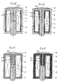
- the in FIG. 1 shown lifting magnet consists of a substantially cup-shaped magnetic body (1) made of solid iron, a Magneterregerspule 3 and a movable armature 6 in the axial direction, as part of the magnetic body 1 is an axially aligned armature 3 armature counterpart 1.1 also made of solid iron. Between the armature counterpart 1.1 and the armature 6 is a bridge 4 made of non-magnetic, ie non-magnetic material. The bridge 4 forms a generally tubular guide element for the armature 6 in the working air gap 5. For pressure equalization, the armature counterpart 1.1 is provided in each case with a connected to the working air gap 5 pressure equalization hole 1.2.
- FIGS. 2 to 11 represented elements representing the representation of FIG. 1 correspond, have the same reference numerals.
- the known solenoid according to FIG. 1 contains parasitic regions 2 in the form of air gaps and / or antimagnetic substances between the iron circuit 1, 11 and 6 and the exciter coil. 3
- the in FIG. 2 Lifting magnet shown consists of a solid iron cup-shaped magnetic body 1 including the armature counterpart 1.1, the armature 6 and the excitation coil 3, which is wound on a non-magnetic coil carrier 7, which is also effective as a bridge between the armature counterpart 1.1 and the movable armature 6.
- the according to FIG. 1 existing air gaps are thus eliminated by the bobbin 7 and the filling 9.
- FIG. 3 Lifting magnet shown consists of a cup-shaped magnetic body 1 including armature counterpart 1.1, the armature 6, the excitation coil 3 and a bridge 4.
- the according to FIG. 1 existing air gaps around the exciter coil 3, that is, the parasitic regions take a filling 9 of magnetically conductive material.
- the in FIG. 4 Lifting magnet shown consists of a static magnetic body 1 including armature counterpart 1.1, an armature 6, an excitation coil 3 and a bridge 4.
- the adjoining the working air gap 5 pressure equalization hole 1.2 opens into a
- the working air gap 5, the pressure equalization bore 1.2 and the pressure equalization chamber 8.1 contain a filling of magnetically conductive material, such as a ferrofluid or a magnetorheological fluid with optionally mixed iron powder or a magnetically conductive paste.
- the solid iron body 1 consisting of solid iron is designed so that parasitic areas, for example in the form of air gaps, are substantially absent, except for the working air gap 5 between the armature 6 and the armature core counterpart 1.1, which according to the embodiment of FIG. 5 is connected via the pressure equalization hole 1.2 to a sealed by a membrane 8 pressure equalization chamber 8.1.
- the inherently parasitic regions of the working air gap 5, the bore 1.2 and the pressure equalization chamber 8.1 contain a filling of magnetically conductive material.
- Solenoid 1 including armature counterpart 1.1, both consisting for example of a magnetically conductive Vergusskapselung, an armature 6 and a coil carrier 7.
- armature counterpart 1.1 both consisting for example of a magnetically conductive Vergusskapselung, an armature 6 and a coil carrier 7.
- the bore 1.2 1.2 in the armature counterpart 1.1 and Pressure Compensating Chamber 8.1 receives a flowable filling of magnetically conductive material.
- the solenoid according to FIG. 9 is made of solid iron, static magnetic body 11 is reduced to a cover 11.2 and the dynamic armature 6 opposite armature counterpart 11.1, which has a working air gap 5 with the pressure equalization chamber 8.1 connecting bore 11.12; the rooms 5, 8.1 and 11.12 take up a magnetically conductive, flowable filling.
- the field coil 3 is wound onto a coil carrier 7 and embedded in a parasitic areas excluding pot 12 of magnetically conductive material, for example, preferably in the form of a potting compound with admixed iron solids, wherein the rigid potting compound is formed by curing a suitable fluid.
- FIG. 10 is the existing solid iron, static magnetic body 11 on a dynamic magnetic core or armature 6 opposite magnetic core counterpart 11.1 and a lid 11.2 reduced.
- the excitation coil 3 is wound onto a bobbin 7 and according to the present invention of a parasitic areas excluding pot 12 according to FIG. 9 surrounded by magnetically conductive material. It lacks here a pressure equalization chamber and the filling of the working air gap 5 and the bore 11.1 with magnetically conductive material.
- the static magnetic body 11 consisting of solid iron is reduced to a cover 11.2, an armature counterpart 11.1 and a bottom section 11.3.
- the wound on a bobbin 7 exciter coil 3 is surrounded by a cylinder 13 of magnetically conductive material, preferably in the form of a potting compound with admixed iron solids, said rigid potting compound is formed by curing a suitable fluid.
- the magnetic efficiency considered here is independent of the switch-on time.
- the magnetic efficiency is defined as the quotient of the mechanically usable energy released in the stationary case to the ideally converted final energy.
- the magnetic efficiency also depends in particular on the size of the magnet system; For example, very small magnet systems usually have lower magnetic efficiencies than larger magnet systems, but this is independent of the actual optimization.
- a magnetic efficiency of about 60% could be measured without application of the principle according to the invention, ie without optimization in the sense of the present invention.
- the magnetic efficiency was 70%, i.
- improved by 10 percentage points which corresponds to an efficiency improvement in the range of 16 to 17%.
Abstract
Description
Die Erfindung betrifft einen Hubmagneten, enthaltend einen topfförmigen Magnetkörper aus massivem Eisen, einen Magnetanker sowie mindestens eine Erregerspule.The invention relates to a lifting magnet, comprising a cup-shaped magnetic body made of solid iron, a magnet armature and at least one exciting coil.
Bei der Konstruktion von Hubmagneten in Form von sogenannten Topfinagneten treten sogenannte parasitäre Bereiche auf, die physikalisch gesehen große magnetische Widerstände darstellen, die beim Betrieb des Magnetsystems zu erheblichen magnetischen Gesamtflussverlusten führen. Diese Verluste äußern sich je nach Ausführungsart der Hubmagnete unterschiedlich und verringern insbesondere die Hubarbeit des Magneten erheblich.In the design of solenoids in the form of so-called Topfinagnet occur so-called parasitic areas, which physically represent large magnetic resistances, which lead to significant magnetic flux loss during operation of the magnet system. These losses are different depending on the design of the solenoids and reduce in particular the lifting of the magnet considerably.
Parasitäre Bereiche werden gebildet durch in einen Hubmagneten integrierte, magnetisch nicht leitende Medien, wie beispielsweise Luft, Gase, oder durch nicht leitende Feststoffe, wie beispielsweise Kunststoff, Pappe oder dergleichen. Die durch solche Medien / Feststoffe entstehenden parasitären Bereiche führen zu einem geringeren magnetischen Gesamtfluss durch den Eisenkreis des elektromagnetischen Systems. Derartige parasitäre Bereiche lassen sich häufig herstellungsbedingt nicht vermeiden, insbesondere, wenn bei der Herstellung der Magnete, insbesondere Hubmagnete, konfektionierte Ausgangsmaterialien verwendet werden, die zu Spalten oder Hohlräumen zwischen den einzelnen Bauteilen führen.Parasitic regions are formed by magnetically non-conductive media, such as air, gases, or non-conductive solids, such as plastic, cardboard, or the like, integrated into a solenoid. The parasitic areas created by such media / solids result in less overall magnetic flux through the iron loop of the electromagnetic system. Frequently, such parasitic areas can not be avoided due to the production, in particular if prefabricated starting materials are used in the production of the magnets, in particular lifting magnets, which lead to gaps or cavities between the individual components.
Die Erfindung geht aus von einem in der
In der
Der Erfindung liegt die Aufgabe zugrunde, Maßnahmen zu treffen, um Hubmagnete zu optimieren, indem die durch "parasitäre" Bereiche entstehenden Verluste vermieden oder zumindest weitgehend herabgesetzt werden.The invention has for its object to take measures to optimize solenoids by avoiding the losses resulting from "parasitic" areas or at least largely reduced.
Zur Lösung dieser Aufgabe ist erfindungsgemäß vorgesehen, dass diese parasitären Bereiche je nach technischer Umsetzbarkeit und ohne Beeinträchtigung der erforderlichen elektrischen Isolierung und Absicherung ganz oder zumindest teilweise durch magnetisch leitfähige Materialien ausgefüllt bzw. ersetzt sind.To achieve this object, the invention provides that these parasitic areas are filled or replaced completely or at least partially by magnetically conductive materials depending on the technical feasibility and without affecting the required electrical insulation and protection.
Die magnetisch leitenden Materialien können sowohl in fester Form, wie beispielsweise in Form von Eisenpulver (Eisen steht im folgenden immer als Synonym für magnetisch leitende Werkstoffe), mit idealerweise sehr kleinen Teilchengrößen unter 5µm (wodurch ein Ausfüllen der parasitären Bereiche zu annähernd 100 % ermöglicht wird), massiven Eisenblechen, Eisenspänen oder ähnlichem, als auch in flüssiger Form, wie magnetorheologische Flüssigkeiten oder Ferrofluiden vorliegen.The magnetically conductive materials can be both in solid form, such as in the form of iron powder (iron is hereinafter always synonymous with magnetically conductive materials), ideally with very small particle sizes below 5 microns (which allows filling of the parasitic regions to approximately 100% ), massive iron sheets, iron filings or the like, as well as in liquid form, such as magnetorheological fluids or ferrofluids.
Eine weitere, sehr effiziente Möglichkeit die parasitären Bereiche zu eliminieren, besteht in einem Fluid, welches seinen Aggregatzustand von zunächst fließfähig zu (nach einer gewissen Aushärtezeit) fest ändert. Diese Fähigkeit besitzen beispielsweise diverse Vergussmassen wie vorzugsweise Zweikomponenten Epoxidharze, Zweikomponenten-Siliconharzen, Zweikomponentenharzen auf der Basis von organischen Kunstharzen usw.. Diese Vergussmassen besitzen den positiven Nebeneffekt einer hohen Wärmeleitfähigkeit; sie haben jedoch den Nachteil, magnetisch nicht leitfähig zu sein. Sie werden erfindungsgemäß daher durch Beimischen von Eisenfeststoffen in vorzugsweise sehr kleinen Teilchengrößen von vorzugsweise unter 5µm und mit Volumenanteilen zwischen 50 bis 95 Vol.-%, vorzugsweise im Bereich von etwa 80 - 85 Vol.-%, magnetisch leitfähig gemacht. Der große Vorteil dieser Vorgehensweise liegt
- a) in einer zusätzlichen besseren Wärmeleitfähigkeit des Magnetsystems, das mit der magnetisch leitfähigen Vergussmasse vergossen wurde, sowie darin, dass
- b) die Vergussmasse in flüssiger Form auch in die noch so kleinsten Winkel des Magnetsystems einfließen kann, ohne später wieder auslaufen zukönnen, da sie ja komplett aushärtet.
- a) in an additional better thermal conductivity of the magnet system, which was potted with the magnetically conductive potting compound, and in that
- b) the potting compound in liquid form can also flow into the smallest angle of the magnet system, without being able to leak later, since it cures completely.
Der Aggregatzustand der Vergussmasse steigt mit dem Feststoffanteil in der Vergussmasse von einer geringen Viskosität bei z.B. 50 Vol.-% stetig und ähnelt bei knapp unter 95 Vol.-% dem einer Paste. Im Einzelfall hängt die Konzentration der Eisenpartikel in der Vergussmasse daher zum einen von der Anfangsviskosität (Trägermedium ohne beigemischte Eisenpartikel) ab, (je geringer die Anfangsviskosität des Trägermediums ist, desto mehr Feststoffe können beigemischt werden) als auch von dem einzelnen Einsatzbereich, indem abgeschätzt wird, ob die magnetische Vergussmasse noch eigenständig fließfähig sein muss, oder ob sie auch in Form einer Paste mit hoher Viskosität [aber auch einem hohen Eisenanteil] durch Einpressen in den Luftspalt eingesetzt wird.The aggregate state of the potting compound increases with the solids content in the potting compound of a low viscosity at e.g. 50 vol .-% steadily and is similar to just under 95 vol .-% of a paste. In individual cases, the concentration of the iron particles in the potting compound therefore depends on the one hand on the initial viscosity (carrier medium without mixed iron particles), (the lower the initial viscosity of the carrier medium, the more solids can be mixed) as well as on the individual application area by estimating whether the magnetic potting compound still has to be independently flowable, or whether it is also used in the form of a paste with high viscosity [but also a high iron content] by pressing into the air gap.
Erfindungsgemäß besteht je nach Anwendungszweck auch die Möglichkeit, Einkomponentenkleber, Silicon oder ähnliches als Trägerstoff für die Eisenpartikeln magnetisch leitfähig zu machen und einzusetzen.According to the invention, depending on the application, it is also possible to make one-component adhesives, silicone or the like magnetically conductive as a carrier for the iron particles and to use them.
Eine vorteilhafte Möglichkeit der Reduzierung der magnetischen Widerstände in den parasitären Bereichen besteht in der Verwendung einer magnetisch gut leitfähigen Paste aus beispielsweise einem Gemisch aus Öl als Trägerfluid und Eisenpulver in einer hohen Konzentration, um die daraus entstehende Paste durch intensives Vermischen homogen magnetisch leitfähig zu machen.An advantageous possibility of reducing the magnetic resistances in the parasitic regions is the use of a magnetically highly conductive paste of, for example, a mixture of oil as a carrier fluid and iron powder in a high concentration to make the resulting paste homogeneous magnetic conductive by intensive mixing.
Diese Paste härtet zwar nicht aus, was aber in manchen Einsatzbereichen geeigneter ist als eine Vergussmasse, die nach dem Befüllen der parasitären Bereiche aushärtet.Although this paste does not cure, but in some applications is more suitable than a potting compound that hardens after filling the parasitic areas.
Die Erfindung wird im folgenden anhand eines Hubmagneten in Form eines Topfmagneten beschrieben.
-
Figur 1 - Die
Figuren 2 bis 11
-
FIG. 1 shows a schematic representation of a sectional view of a known lifting magnet; - The
FIGS. 2 to 11 show in a schematic representation sectional views of various embodiments inventively designed lifting magnets.
Der in
In den
Der bekannte Hubmagnet gemäß
Der in
Der in
Der in
Bei dem Hubmagneten gemäß
Bei dem Hubmagneten gemäß
Bei der Ausführungsform gemäß
Der in
Bei dem Hubmagneten gemäß
Bei der Ausführungsform gemäß
Bei der Ausführungsform gemäß
Bei Anwendung des erfindungsgemäßen Prinzips können beträchtliche Verbesserungen erreicht werden.When applying the principle according to the invention, considerable improvements can be achieved.
Grundlegend ist festzuhalten, dass in diesem Zusammenhang bei der Optimierung nur der magnetische Wirkungsgrad betrachtet wird, da dieser nicht, wie es beim Gesamtwirkungsgrad der Fall ist, von der Einschaltzeit abhängt. Bei gegen unendlich strebender Einschaltzeit mit der daraus resultierenden gegen unendlich strebenden Verlustenergie, nähert sich der Gesamtwirkungsgrad dem Wert 0, da der gesamte Energieaufwand sich nur noch in Verlustenergie in Form von Wärme umwandelt. Der hier betrachtete magnetische Wirkungsgrad hingegen ist von der Einschaltzeit unabhängig. Der magnetische Wirkungsgrad ist definiert als der Quotient, der im stationären Fall frei werdenden mechanisch nutzbaren Energie zu der im Idealfall umgewandelten Endenergie.Basically, it should be noted that in this context, only the magnetic efficiency is considered in the optimization, since this does not depend on the turn-on time, as is the case with the overall efficiency. When the on-time is approaching infinity with the resulting loss energy towards infinity, the overall efficiency approaches 0 because the total energy expenditure is only converted into energy lost in the form of heat. By contrast, the magnetic efficiency considered here is independent of the switch-on time. The magnetic efficiency is defined as the quotient of the mechanically usable energy released in the stationary case to the ideally converted final energy.
Numerisch hängt der magnetische Wirkungsgrad insbesondere auch von der Größe des Magnetsystems ab; so haben sehr kleine Magnetsysteme in der Regel geringere magnetische Wirkungsgrade als größere Magnetsysteme, was jedoch von der eigentlichen Optimierung unabhängig ist. Für einen bestimmten Prototypen eines Magnetsystems konnte ohne Anwendung des erfindungsgemäßen Prinzips, also ohne Optimierung im Sinne der vorliegenden Erfindung ein magnetischer Wirkungsgrad von ca. 60 % gemessen werden. Nach der Optimierung mit einer aushärtenden Vergussmasse, die einen Eisenpulveranteil im Bereich von 70 Vol.-% enthielt, hat sich der magnetische Wirkungsgrad auf 70 %, d.h. also um 10 %-Punkte verbessert, was einer Wirkungsgradverbesserung im Bereich von 16 bis 17 % entspricht. Durch Ausfüllen der parasitären Luftbereiche bis zu annähernd 100 % mit Eisenpulver kann eine weitere Wirkungsgradverbesserung erreicht werden, wobei zu beachten ist, dass grundsätzlich der magnetische Wirkungsgrad maximal auf einen Wert von ca. 80 % verbessert werden kann, wobei es sich dann allerdings um ein ideales Magnetsystem ohne irgendwelche parasitären Bereiche handelte.Numerically, the magnetic efficiency also depends in particular on the size of the magnet system; For example, very small magnet systems usually have lower magnetic efficiencies than larger magnet systems, but this is independent of the actual optimization. For a specific prototype of a magnet system, a magnetic efficiency of about 60% could be measured without application of the principle according to the invention, ie without optimization in the sense of the present invention. After optimization with a curing potting compound containing an iron powder content in the range of 70% by volume, the magnetic efficiency was 70%, i. Thus, improved by 10 percentage points, which corresponds to an efficiency improvement in the range of 16 to 17%. By filling the parasitic air areas up to approximately 100% with iron powder, a further improvement in efficiency can be achieved, it being noted that in principle the maximum magnetic efficiency can be improved to a value of about 80%, but this is then an ideal Magnetic system without any parasitic areas acted.
Claims (18)
Applications Claiming Priority (1)
| Application Number | Priority Date | Filing Date | Title |
|---|---|---|---|
| DE200710053005 DE102007053005A1 (en) | 2007-11-05 | 2007-11-05 | Solenoid and method for improving the efficiency of solenoids |
Publications (2)
| Publication Number | Publication Date |
|---|---|
| EP2056308A1 true EP2056308A1 (en) | 2009-05-06 |
| EP2056308B1 EP2056308B1 (en) | 2013-09-18 |
Family
ID=40229763
Family Applications (1)
| Application Number | Title | Priority Date | Filing Date |
|---|---|---|---|
| EP20080018926 Not-in-force EP2056308B1 (en) | 2007-11-05 | 2008-10-30 | Solenoid |
Country Status (2)
| Country | Link |
|---|---|
| EP (1) | EP2056308B1 (en) |
| DE (1) | DE102007053005A1 (en) |
Families Citing this family (1)
| Publication number | Priority date | Publication date | Assignee | Title |
|---|---|---|---|---|
| DE102011006071A1 (en) | 2011-03-24 | 2012-09-27 | Ina - Drives & Mechatronics Gmbh & Co. Ohg | Drive device for a valve, valve for controlling a gas and / or liquid flow |
Citations (3)
| Publication number | Priority date | Publication date | Assignee | Title |
|---|---|---|---|---|
| EP0052177A1 (en) | 1980-11-15 | 1982-05-26 | WABCO Westinghouse Fahrzeugbremsen GmbH | Solenoid valve |
| DE10139447A1 (en) | 2001-08-10 | 2003-02-20 | Conti Temic Microelectronic | Coil structure, especially for motor vehicle controllers, has coil yoke in form of setting material in which wire arrangement is embedded and that has magnetic properties |
| DE102004023905A1 (en) | 2004-05-13 | 2005-12-22 | Bürkert Werke GmbH & Co. KG | Electromagnetic actuation equipment for switching and proportional valves, has central guide tube made of magnetically conducting material permeability of which is lower than permeability of yoke and central stationary and moving parts |
Family Cites Families (3)
| Publication number | Priority date | Publication date | Assignee | Title |
|---|---|---|---|---|
| DE3239345A1 (en) * | 1982-10-23 | 1984-04-26 | bso Steuerungstechnik GmbH, 6603 Sulzbach | ACTUATING MAGNET |
| US5955394A (en) * | 1996-08-16 | 1999-09-21 | Mobile Process Technology, Co. | Recovery process for oxidation catalyst in the manufacture of aromatic carboxylic acids |
| DE19914020C1 (en) * | 1999-03-19 | 2000-08-31 | Siemens Ag | Coil-wound hardware items noise reduction procedure especially for chokes and transformers |
-
2007
- 2007-11-05 DE DE200710053005 patent/DE102007053005A1/en not_active Withdrawn
-
2008
- 2008-10-30 EP EP20080018926 patent/EP2056308B1/en not_active Not-in-force
Patent Citations (3)
| Publication number | Priority date | Publication date | Assignee | Title |
|---|---|---|---|---|
| EP0052177A1 (en) | 1980-11-15 | 1982-05-26 | WABCO Westinghouse Fahrzeugbremsen GmbH | Solenoid valve |
| DE10139447A1 (en) | 2001-08-10 | 2003-02-20 | Conti Temic Microelectronic | Coil structure, especially for motor vehicle controllers, has coil yoke in form of setting material in which wire arrangement is embedded and that has magnetic properties |
| DE102004023905A1 (en) | 2004-05-13 | 2005-12-22 | Bürkert Werke GmbH & Co. KG | Electromagnetic actuation equipment for switching and proportional valves, has central guide tube made of magnetically conducting material permeability of which is lower than permeability of yoke and central stationary and moving parts |
Also Published As
| Publication number | Publication date |
|---|---|
| EP2056308B1 (en) | 2013-09-18 |
| DE102007053005A1 (en) | 2009-05-07 |
Similar Documents
| Publication | Publication Date | Title |
|---|---|---|
| EP2463869B2 (en) | Inductive component with improved core properties | |
| EP2238601B1 (en) | Inductor and method for production of an inductor core unit for an inductor | |
| DE3401598A1 (en) | LINEAR ACTUATOR WITH HYBRID STRUCTURE | |
| DE102009053965B4 (en) | With a potting compound poured gradient coil | |
| EP3494632B1 (en) | Motor component, primary part and linear motor | |
| DE1935929A1 (en) | Electrical device | |
| DE112015003006T5 (en) | Core element, inductor and method of manufacturing the core element | |
| DE3005573A1 (en) | PERMANENT MAGNET | |
| DE3011079A1 (en) | METHOD FOR PRODUCING A MAGNETIC TANK DIVIDED STRUCTURE AND ANCHOR ACCORDING TO THIS METHOD | |
| DE102015101230A1 (en) | inductor | |
| DE102013007563A1 (en) | Rotor for an electric machine | |
| DE102018116323A1 (en) | Three-phase choke | |
| DE102013102400B4 (en) | Electromagnetic actuator and combination of electromagnetic actuator and motor spindle | |
| DE202005008757U1 (en) | transformer | |
| DE102008027759A1 (en) | Rotor for permanent magnet-actuating dynamo-electric machine, has rotor base body, which has medium for guiding and generating magnetic field | |
| DE102007054917A1 (en) | Electromagnetic device's e.g. electromagnetic brake, efficiency optimizing method, involves filling out parasitic areas in region of body and wire wound coil of electromagnetic device by conductive materials, and embedding areas into matrix | |
| DE102006052629B4 (en) | magnetic valve | |
| EP3001544A1 (en) | Active part as rotor or stator, method for the production of such an active part, and an electric machine | |
| EP2056308A1 (en) | Solenoid | |
| DE202007015492U1 (en) | solenoid | |
| DE102011007334A1 (en) | Liquid-cooled inductive component | |
| EP1501106B1 (en) | Ferrite core for inductive element | |
| EP2561520A1 (en) | Inductive component having variable core characteristics and method for setting same | |
| DE102013111079B4 (en) | Pulse solenoid valve | |
| DE2364350A1 (en) | ELECTRO-HYDRAULIC SERVO DISTRIBUTOR |
Legal Events
| Date | Code | Title | Description |
|---|---|---|---|
| PUAI | Public reference made under article 153(3) epc to a published international application that has entered the european phase |
Free format text: ORIGINAL CODE: 0009012 |
|
| AK | Designated contracting states |
Kind code of ref document: A1 Designated state(s): AT BE BG CH CY CZ DE DK EE ES FI FR GB GR HR HU IE IS IT LI LT LU LV MC MT NL NO PL PT RO SE SI SK TR |
|
| AX | Request for extension of the european patent |
Extension state: AL BA MK RS |
|
| 17P | Request for examination filed |
Effective date: 20091103 |
|
| AKX | Designation fees paid |
Designated state(s): AT BE BG CH CY CZ DE DK EE ES FI FR GB GR HR HU IE IS IT LI LT LU LV MC MT NL NO PL PT RO SE SI SK TR |
|
| GRAP | Despatch of communication of intention to grant a patent |
Free format text: ORIGINAL CODE: EPIDOSNIGR1 |
|
| 17Q | First examination report despatched |
Effective date: 20130118 |
|
| INTG | Intention to grant announced |
Effective date: 20130411 |
|
| GRAS | Grant fee paid |
Free format text: ORIGINAL CODE: EPIDOSNIGR3 |
|
| GRAA | (expected) grant |
Free format text: ORIGINAL CODE: 0009210 |
|
| AK | Designated contracting states |
Kind code of ref document: B1 Designated state(s): AT BE BG CH CY CZ DE DK EE ES FI FR GB GR HR HU IE IS IT LI LT LU LV MC MT NL NO PL PT RO SE SI SK TR |
|
| REG | Reference to a national code |
Ref country code: GB Ref legal event code: FG4D Free format text: NOT ENGLISH |
|
| REG | Reference to a national code |
Ref country code: CH Ref legal event code: EP |
|
| REG | Reference to a national code |
Ref country code: IE Ref legal event code: FG4D Free format text: LANGUAGE OF EP DOCUMENT: GERMAN |
|
| REG | Reference to a national code |
Ref country code: AT Ref legal event code: REF Ref document number: 633161 Country of ref document: AT Kind code of ref document: T Effective date: 20131015 |
|
| REG | Reference to a national code |
Ref country code: DE Ref legal event code: R096 Ref document number: 502008010670 Country of ref document: DE Effective date: 20131114 |
|
| REG | Reference to a national code |
Ref country code: NL Ref legal event code: T3 |
|
| PG25 | Lapsed in a contracting state [announced via postgrant information from national office to epo] |
Ref country code: LT Free format text: LAPSE BECAUSE OF FAILURE TO SUBMIT A TRANSLATION OF THE DESCRIPTION OR TO PAY THE FEE WITHIN THE PRESCRIBED TIME-LIMIT Effective date: 20130918 Ref country code: NO Free format text: LAPSE BECAUSE OF FAILURE TO SUBMIT A TRANSLATION OF THE DESCRIPTION OR TO PAY THE FEE WITHIN THE PRESCRIBED TIME-LIMIT Effective date: 20131218 Ref country code: CY Free format text: LAPSE BECAUSE OF FAILURE TO SUBMIT A TRANSLATION OF THE DESCRIPTION OR TO PAY THE FEE WITHIN THE PRESCRIBED TIME-LIMIT Effective date: 20130731 Ref country code: HR Free format text: LAPSE BECAUSE OF FAILURE TO SUBMIT A TRANSLATION OF THE DESCRIPTION OR TO PAY THE FEE WITHIN THE PRESCRIBED TIME-LIMIT Effective date: 20130918 Ref country code: SE Free format text: LAPSE BECAUSE OF FAILURE TO SUBMIT A TRANSLATION OF THE DESCRIPTION OR TO PAY THE FEE WITHIN THE PRESCRIBED TIME-LIMIT Effective date: 20130918 |
|
| REG | Reference to a national code |
Ref country code: LT Ref legal event code: MG4D |
|
| PG25 | Lapsed in a contracting state [announced via postgrant information from national office to epo] |
Ref country code: LV Free format text: LAPSE BECAUSE OF FAILURE TO SUBMIT A TRANSLATION OF THE DESCRIPTION OR TO PAY THE FEE WITHIN THE PRESCRIBED TIME-LIMIT Effective date: 20130918 Ref country code: GR Free format text: LAPSE BECAUSE OF FAILURE TO SUBMIT A TRANSLATION OF THE DESCRIPTION OR TO PAY THE FEE WITHIN THE PRESCRIBED TIME-LIMIT Effective date: 20131219 Ref country code: ES Free format text: LAPSE BECAUSE OF FAILURE TO SUBMIT A TRANSLATION OF THE DESCRIPTION OR TO PAY THE FEE WITHIN THE PRESCRIBED TIME-LIMIT Effective date: 20130918 Ref country code: SI Free format text: LAPSE BECAUSE OF FAILURE TO SUBMIT A TRANSLATION OF THE DESCRIPTION OR TO PAY THE FEE WITHIN THE PRESCRIBED TIME-LIMIT Effective date: 20130918 Ref country code: FI Free format text: LAPSE BECAUSE OF FAILURE TO SUBMIT A TRANSLATION OF THE DESCRIPTION OR TO PAY THE FEE WITHIN THE PRESCRIBED TIME-LIMIT Effective date: 20130918 |
|
| PG25 | Lapsed in a contracting state [announced via postgrant information from national office to epo] |
Ref country code: CY Free format text: LAPSE BECAUSE OF FAILURE TO SUBMIT A TRANSLATION OF THE DESCRIPTION OR TO PAY THE FEE WITHIN THE PRESCRIBED TIME-LIMIT Effective date: 20130918 |
|
| BERE | Be: lapsed |
Owner name: UNI-GERATE E. MANGELMANN ELEKTROTECHNISCHE FABRIK Effective date: 20131031 |
|
| PG25 | Lapsed in a contracting state [announced via postgrant information from national office to epo] |
Ref country code: SK Free format text: LAPSE BECAUSE OF FAILURE TO SUBMIT A TRANSLATION OF THE DESCRIPTION OR TO PAY THE FEE WITHIN THE PRESCRIBED TIME-LIMIT Effective date: 20130918 Ref country code: IS Free format text: LAPSE BECAUSE OF FAILURE TO SUBMIT A TRANSLATION OF THE DESCRIPTION OR TO PAY THE FEE WITHIN THE PRESCRIBED TIME-LIMIT Effective date: 20140118 Ref country code: CZ Free format text: LAPSE BECAUSE OF FAILURE TO SUBMIT A TRANSLATION OF THE DESCRIPTION OR TO PAY THE FEE WITHIN THE PRESCRIBED TIME-LIMIT Effective date: 20130918 Ref country code: RO Free format text: LAPSE BECAUSE OF FAILURE TO SUBMIT A TRANSLATION OF THE DESCRIPTION OR TO PAY THE FEE WITHIN THE PRESCRIBED TIME-LIMIT Effective date: 20130918 Ref country code: EE Free format text: LAPSE BECAUSE OF FAILURE TO SUBMIT A TRANSLATION OF THE DESCRIPTION OR TO PAY THE FEE WITHIN THE PRESCRIBED TIME-LIMIT Effective date: 20130918 |
|
| PG25 | Lapsed in a contracting state [announced via postgrant information from national office to epo] |
Ref country code: PL Free format text: LAPSE BECAUSE OF FAILURE TO SUBMIT A TRANSLATION OF THE DESCRIPTION OR TO PAY THE FEE WITHIN THE PRESCRIBED TIME-LIMIT Effective date: 20130918 |
|
| REG | Reference to a national code |
Ref country code: CH Ref legal event code: PL |
|
| REG | Reference to a national code |
Ref country code: DE Ref legal event code: R097 Ref document number: 502008010670 Country of ref document: DE |
|
| PG25 | Lapsed in a contracting state [announced via postgrant information from national office to epo] |
Ref country code: MC Free format text: LAPSE BECAUSE OF FAILURE TO SUBMIT A TRANSLATION OF THE DESCRIPTION OR TO PAY THE FEE WITHIN THE PRESCRIBED TIME-LIMIT Effective date: 20130918 Ref country code: PT Free format text: LAPSE BECAUSE OF FAILURE TO SUBMIT A TRANSLATION OF THE DESCRIPTION OR TO PAY THE FEE WITHIN THE PRESCRIBED TIME-LIMIT Effective date: 20140120 |
|
| PLBE | No opposition filed within time limit |
Free format text: ORIGINAL CODE: 0009261 |
|
| STAA | Information on the status of an ep patent application or granted ep patent |
Free format text: STATUS: NO OPPOSITION FILED WITHIN TIME LIMIT |
|
| REG | Reference to a national code |
Ref country code: IE Ref legal event code: MM4A |
|
| PG25 | Lapsed in a contracting state [announced via postgrant information from national office to epo] |
Ref country code: LI Free format text: LAPSE BECAUSE OF NON-PAYMENT OF DUE FEES Effective date: 20131031 Ref country code: CH Free format text: LAPSE BECAUSE OF NON-PAYMENT OF DUE FEES Effective date: 20131031 |
|
| 26N | No opposition filed |
Effective date: 20140619 |
|
| REG | Reference to a national code |
Ref country code: DE Ref legal event code: R097 Ref document number: 502008010670 Country of ref document: DE Effective date: 20140619 |
|
| PG25 | Lapsed in a contracting state [announced via postgrant information from national office to epo] |
Ref country code: DK Free format text: LAPSE BECAUSE OF FAILURE TO SUBMIT A TRANSLATION OF THE DESCRIPTION OR TO PAY THE FEE WITHIN THE PRESCRIBED TIME-LIMIT Effective date: 20130918 Ref country code: BE Free format text: LAPSE BECAUSE OF NON-PAYMENT OF DUE FEES Effective date: 20131031 |
|
| PG25 | Lapsed in a contracting state [announced via postgrant information from national office to epo] |
Ref country code: IE Free format text: LAPSE BECAUSE OF NON-PAYMENT OF DUE FEES Effective date: 20131030 |
|
| REG | Reference to a national code |
Ref country code: AT Ref legal event code: MM01 Ref document number: 633161 Country of ref document: AT Kind code of ref document: T Effective date: 20131030 |
|
| PGFP | Annual fee paid to national office [announced via postgrant information from national office to epo] |
Ref country code: DE Payment date: 20141222 Year of fee payment: 7 |
|
| PG25 | Lapsed in a contracting state [announced via postgrant information from national office to epo] |
Ref country code: AT Free format text: LAPSE BECAUSE OF NON-PAYMENT OF DUE FEES Effective date: 20131030 |
|
| REG | Reference to a national code |
Ref country code: FR Ref legal event code: PLFP Year of fee payment: 7 |
|
| PG25 | Lapsed in a contracting state [announced via postgrant information from national office to epo] |
Ref country code: TR Free format text: LAPSE BECAUSE OF FAILURE TO SUBMIT A TRANSLATION OF THE DESCRIPTION OR TO PAY THE FEE WITHIN THE PRESCRIBED TIME-LIMIT Effective date: 20130918 |
|
| PGFP | Annual fee paid to national office [announced via postgrant information from national office to epo] |
Ref country code: NL Payment date: 20150422 Year of fee payment: 7 |
|
| PG25 | Lapsed in a contracting state [announced via postgrant information from national office to epo] |
Ref country code: HU Free format text: LAPSE BECAUSE OF FAILURE TO SUBMIT A TRANSLATION OF THE DESCRIPTION OR TO PAY THE FEE WITHIN THE PRESCRIBED TIME-LIMIT; INVALID AB INITIO Effective date: 20081030 Ref country code: BG Free format text: LAPSE BECAUSE OF FAILURE TO SUBMIT A TRANSLATION OF THE DESCRIPTION OR TO PAY THE FEE WITHIN THE PRESCRIBED TIME-LIMIT Effective date: 20130918 Ref country code: LU Free format text: LAPSE BECAUSE OF NON-PAYMENT OF DUE FEES Effective date: 20131030 |
|
| PGFP | Annual fee paid to national office [announced via postgrant information from national office to epo] |
Ref country code: GB Payment date: 20150423 Year of fee payment: 7 |
|
| PG25 | Lapsed in a contracting state [announced via postgrant information from national office to epo] |
Ref country code: MT Free format text: LAPSE BECAUSE OF FAILURE TO SUBMIT A TRANSLATION OF THE DESCRIPTION OR TO PAY THE FEE WITHIN THE PRESCRIBED TIME-LIMIT Effective date: 20130918 |
|
| PGFP | Annual fee paid to national office [announced via postgrant information from national office to epo] |
Ref country code: IT Payment date: 20150423 Year of fee payment: 7 Ref country code: FR Payment date: 20150422 Year of fee payment: 7 |
|
| REG | Reference to a national code |
Ref country code: DE Ref legal event code: R119 Ref document number: 502008010670 Country of ref document: DE |
|
| GBPC | Gb: european patent ceased through non-payment of renewal fee |
Effective date: 20151030 |
|
| REG | Reference to a national code |
Ref country code: NL Ref legal event code: MM Effective date: 20151101 |
|
| PG25 | Lapsed in a contracting state [announced via postgrant information from national office to epo] |
Ref country code: DE Free format text: LAPSE BECAUSE OF NON-PAYMENT OF DUE FEES Effective date: 20160503 Ref country code: GB Free format text: LAPSE BECAUSE OF NON-PAYMENT OF DUE FEES Effective date: 20151030 Ref country code: IT Free format text: LAPSE BECAUSE OF NON-PAYMENT OF DUE FEES Effective date: 20151030 |
|
| REG | Reference to a national code |
Ref country code: FR Ref legal event code: ST Effective date: 20160630 |
|
| PG25 | Lapsed in a contracting state [announced via postgrant information from national office to epo] |
Ref country code: NL Free format text: LAPSE BECAUSE OF NON-PAYMENT OF DUE FEES Effective date: 20151101 Ref country code: FR Free format text: LAPSE BECAUSE OF NON-PAYMENT OF DUE FEES Effective date: 20151102 |