EP2055888B1 - Porte dotée d'un joint et joint de porte correspondant - Google Patents
Porte dotée d'un joint et joint de porte correspondant Download PDFInfo
- Publication number
- EP2055888B1 EP2055888B1 EP08405270.3A EP08405270A EP2055888B1 EP 2055888 B1 EP2055888 B1 EP 2055888B1 EP 08405270 A EP08405270 A EP 08405270A EP 2055888 B1 EP2055888 B1 EP 2055888B1
- Authority
- EP
- European Patent Office
- Prior art keywords
- door
- seal
- groove
- seal housing
- housing
- Prior art date
- Legal status (The legal status is an assumption and is not a legal conclusion. Google has not performed a legal analysis and makes no representation as to the accuracy of the status listed.)
- Not-in-force
Links
Images


Classifications
-
- E—FIXED CONSTRUCTIONS
- E06—DOORS, WINDOWS, SHUTTERS, OR ROLLER BLINDS IN GENERAL; LADDERS
- E06B—FIXED OR MOVABLE CLOSURES FOR OPENINGS IN BUILDINGS, VEHICLES, FENCES OR LIKE ENCLOSURES IN GENERAL, e.g. DOORS, WINDOWS, BLINDS, GATES
- E06B7/00—Special arrangements or measures in connection with doors or windows
- E06B7/16—Sealing arrangements on wings or parts co-operating with the wings
- E06B7/18—Sealing arrangements on wings or parts co-operating with the wings by means of movable edgings, e.g. draught sealings additionally used for bolting, e.g. by spring force or with operating lever
- E06B7/20—Sealing arrangements on wings or parts co-operating with the wings by means of movable edgings, e.g. draught sealings additionally used for bolting, e.g. by spring force or with operating lever automatically withdrawn when the wing is opened, e.g. by means of magnetic attraction, a pin or an inclined surface, especially for sills
- E06B7/215—Sealing arrangements on wings or parts co-operating with the wings by means of movable edgings, e.g. draught sealings additionally used for bolting, e.g. by spring force or with operating lever automatically withdrawn when the wing is opened, e.g. by means of magnetic attraction, a pin or an inclined surface, especially for sills with sealing strip being moved to a retracted position by elastic means, e.g. springs
Definitions
- the invention relates to a door seal according to the preamble of patent claim 1.
- EP 1 486 639 proposes to push a spring-trained clip over an upper web of the seal housing and to attach this clip with attached nails from below into the door groove.
- US 3,871,133 discloses a steel door with a lowering seal disposed therein. Between the two side walls of the door a lying c-shaped profile is screwed into which a corresponding guide rail of Absenkdichtung can be inserted.
- EP 0 609 755 describes a profile rail which is screwed in a groove of a door on the ceiling side to receive a correspondingly shaped seal housing form fit.
- the rail and the seal housing on lateral sawtooth profiles, wherein the seal housing is introduced by being knocked or pushed into the rail.
- DE 815 538 shows a sliding seal for a door, wherein the door has a conically undercut groove or a groove with a circular cross section, in each of which a suitably shaped mounting rail of the sliding seal is held in a form-fitting manner.
- GB 2 231 360 describes a arranged in a door groove sliding seal with an inner longitudinal profile, which is held positively in an outer longitudinal profile.
- both longitudinal profiles have teeth, which mesh with each other.
- the outer longitudinal profile rests on side jaws of the end plates, which are screwed to the two opposite ends of the door groove.
- EP 1 138 865 shows an automatically lowered mechanical door seal, which is held thanks to laterally protruding from a seal housing expansion elements in the door groove.
- EP 1 772 586 discloses a machine-mountable bottom seal of a door. It is used a mounting bracket, which is inserted into an intermediate space of the guide rail and, thanks to a resilient tab and a locking lug is positively connected to the guide rail or the seal housing connectable. To fix the seal in the door groove, the angle is screwed with its other leg to the end face of the door. Furthermore, in other embodiments, an expansion element is disclosed, which is arranged in the seal housing, protrudes laterally from this and thus holds the seal in the groove by jamming in the side walls of the door groove.
- door seals are either not suitable for mechanical or automatic attachment, their installation is time consuming and / or it will be needed for the assembly tools.
- the machine-mountable seals described are constructed relatively complicated. They can not be cut and they are more expensive and more prone to failure than simple door seals. Furthermore, the fixation in screwless mounted seals is inadequate, especially in the case of wooden doors. Another disadvantage is that many of these seals can only be dismantled if the door is lifted out of their hinges.
- the door seal according to the invention has a sealing housing, a sealing element held therein and fastening means for fastening the sealing housing in a door groove.
- the seal housing has a web and two laterally disposed legs.
- the fastening means comprises at least one spring element for resilient engagement with a side wall of the door groove, wherein at least one of these spring elements is arranged on each outer surface of each leg of the seal housing.
- a door has a downwardly open door groove, which is formed by material removal.
- a door seal in the door groove arranged, which has a seal housing with a web and two laterally disposed thereon legs, wherein the seal housing is arranged fixed in position in the door groove.
- a stop element serves to fix the seal housing with respect to a movement in the longitudinal direction of the seal housing.
- the stop element is located at a front end of the door groove.
- a fall-out protection element that differs in shape from the stop element secures the seal housing downward with respect to movement.
- the Hinfallfalltikelement is at least partially formed by the door groove.
- the stop element is arranged on the seal housing or it is formed by a, closed at least in an upper region, the end of the door groove, wherein the door groove is formed shorter in this case in this upper region than the width of the door.
- stop element is arranged on the seal housing, then it may be integrally formed on the seal housing or releasably secured to it or not releasably attached thereto.
- the door seal can still be produced as a standard product and used as a storage item.
- the same seal housing can be mounted in different shaped door grooves.
- existing door seals can be easily retrofitted and used in the new inventive door grooves.
- This connection of groove and seal housing is particularly suitable for wooden doors. at most of the door systems of the invention, the assembly is facilitated by the seal can be inserted frontally and often also can be attached without tools. This also facilitates replacement of the seal.
- door leaf which can be used in a door frame.
- the door leaf can be pivoted with respect to the door frame or moved longitudinally. It also means any kind of sliding doors and folding walls.
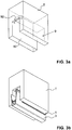
- FIGS. 1a to 1c is a first set of a floor or door seal with a correspondingly adapted, associated door groove shown.
- the door is preferably made of wood.
- FIG. 1a only the guide rail or the seal housing 1 is shown. It can be in it, for example, an automatically mechanically lowered sealing strip as in EP 0 338 974 described and in Figure 3c represented, arrange. It can also arrange other types of lowerable seals and also, for example, sliding seals or magnetic seals.
- the seal housing 1 is in FIG. 1a shown shortened. It is preferably made of aluminum.
- the housing 1 has a substantially U-shaped cross-section with two spaced apart parallel to each other side walls or legs 10 and an upper leg 11 connecting these legs 10 together.
- the housing 1 may have internal ribs, for example for supporting a power transmission rod, which is connected to a lowering mechanism for moving the sealing strip.
- the outer sides of the two legs 10 and the web 11 are preferably formed flat.
- an opening, preferably a through hole 12, is present in the web 11 in the web 11 in the web 11 is adjacent to one end of the housing 1, an opening, preferably a through hole 12, is present.
- This seal housing 1 is, as in FIG. 1a can be seen, a stop bracket 5 connected.
- This stop angle 5 is in FIG. 1b shown. It is preferably made in one piece from metal, in particular steel. He has a leg insertion 51, which can be inserted below the web 11 of the seal housing 1 or plugged onto the seal housing. On the insertion leg 51, a retaining lug 53 is formed, which engages in the inserted state of the stop angle 5 in the opening 12 and forms a snap connection with this. This allows the connection to be made without using a tool. This connection can only be solved by the retention tab is pushed out of the opening, preferably with a tool.
- the retention tab 53 may be arranged on the web of the seal housing 1 and the opening for receiving the retaining lug on the insertion leg 51.
- the stop angle 5 also has a stop leg 50, which is preferably arranged at a right angle to the insertion leg 53. This serves as a stop when mounting the seal in the door groove and is located on an end face of the door above its groove.
- the stop leg 50 may, but need not, be bolted to the door.
- a mounting hole 52 may be provided.
- This stop angle 5 thus serves as a stop element and absorbs the forces resulting from the release of the seal in the longitudinal direction of the seal. It is preferably attached only on one side to the seal housing 1, namely on the side at which the actuating button is located. On the other hand, no corresponding counterpart can be found. Thus, the seal housing 1 and thus the seal from one side can be inserted laterally into the door groove 9 until the stop leg 50 rests against the end face of the door T.
- the door seal can be optionally attached to the door hinge-side end face of the door leaf and / or to the lock-side end face.
- the stop or fastener 5 When mounting on the lock side, ie on the opposite side of the operating knob or rod, the stop or fastener 5 is screwed by means of a screw to counteract the pressure of the actuating rod when closing the door leaf and hold the housing of the door seal so in its position ,
- the corresponding attachment hole 52 is already present in the stop leg 52. This arrangement is chosen especially for door leaves, which are not complete or for the introduction the seal does not open enough. This is usually the case with an opening angle of less than 120 °.
- stop angle 5 is arranged on the door hinge-side end face of the door leaf 1, i. on the side of the control knob, it is unnecessary to screw on the bracket.
- the stop leg 50 serves as a stop and absorbs the pressure generated by the operating knob.
- This type of attachment is mainly used for door leaves, which can open completely or sufficiently wide. Of course, both types of attachment can be used if the door seal is mounted before hanging the door leaf. The latter type has the advantage that no tools for the installation of the seal are necessary. Furthermore, the visual appearance is improved since the door lock side no mounting bracket and no screws are visible.
- the stop element may also be designed differently. It does not necessarily have to be an angle element with two legs. It may, for example, also be formed as a wire part, which is present with two ends laterally on the front side of the door and is hooked with a central bent to a tab part in a retaining lug of the seal housing.
- the door groove 9 is formed continuously in a first embodiment, that is, it extends over the entire width of the door T and is formed on both end faces and open at the bottom. It has a substantially U-shaped cross section with substantially planar and mutually parallel inner side walls 90 and a substantially planar upper ceiling.
- the groove 9 has at its lower end on each longitudinal side 90 an inwardly projecting ledge 91 or projection, so that the stepped groove has a substantially T-shaped cross-section.
- These ledges 91 preferably extend over the entire length of the groove 9. However, they may also be partially interrupted or located only in the two frontal edge regions of the groove 9.
- the stop angle 5 allows easy retrofitting of already produced seals.
- FIG. 2 a second embodiment of a seal housing 1 is shown, which with a stepped groove 9 according to Figure 1c can be used.
- the stop angle is unnecessary 5.
- the seal housing 1 has at one end face at right angles projecting flanges 13, 14, which act as stop elements.
- the legs 10 each have a lateral flange 14 and the web 11 an upper flange 13.
- a flange in particular only an upper flange 13 on the web 11, is formed.
- the flanges 13, 14 are preferably made in one piece with the rail of the seal housing 1. Again, the second end face of the seal housing 1 no stop element.
- FIGS. 3a to 3d a further embodiment of a door T can be seen.
- the groove 9 at a front end to a stop which is formed by an upper rear wall 92. This is obtained in that not all material in the formation of the groove 9 is removed or milled away, but just this top wall 92 or step is left standing. This is relatively easy to produce, especially in wooden doors.
- the seal is secured in the groove 9.
- the groove 9 can again be stepped and provided with the two ledges 91, which are not shown here.
- the groove 9 and the seal housing 1 can also be one of the following with reference to the FIGS. 4 to 8 have described forms together to to make an extra protection.
- the seal housing 1 does not extend over the entire width of the door T, but ends at the upper rear wall 92.
- the sealing strip 3 can be made longer and thus, as shown in this figure, over the entire width of the door T. and, if desired, even extend over one or both sides of the door T. The latter is in 3d figure visible, noticeable.
- support rail 2 which is raised and lowered within the seal housing 1 and carries the sealing strip 3, preferably ends together with the seal housing 1.
- the operating knob 4 projects beyond the door groove 9 preferably at that front end, which is completely open and without stop element. This variant has the advantage that the seal is partially hidden on this end face of the door.
- FIG. 4 a variant of the door groove 9 is shown.
- the upper rear wall 92 goes over a step in a recessed lower rear wall 93 over.
- the upper rear wall 92 serves as a stop for the seal housing 1.
- the lower rear wall 93 terminates at a distance from the seal and thus allows sufficient clearance to avoid grinding of the sealing element in the groove or tilting of the seal.
- the two back walls 92 and 93 may also be aligned.
- This variant has the advantage that the seal from this end face of the door T is not visible.
- This variant can also be formed with or without bottom-side steps 91.
- FIGS. 5a and 5b show a further variant of a fall protection element.
- the one-sided stop element is not shown, but present. It can be formed in different ways.
- the seal housing 1 laterally projecting flanges 13, 14 according to FIG. 2 or with a stop angle 5 according to FIG. 1b be connected.
- the groove 9 with a continuous or partial rear wall 92, 93 according to the FIGS. 3a and 4 be provided.
- FIG. 5b a trapezoidal groove 9 is shown.
- the width of the groove decreases towards its lower open end.
- the cross section of the groove 9 is preferably constant over its entire length, except for a possibly end-side closing stop element.
- FIG. 5a a variant of a matching sealing housing 1 is shown.
- the upper web 11 of the sealing housing 1 has the same width as the uppermost region of the groove 9.
- the lateral limbs 10 of the sealing housing 1 are arranged on the web 11 set back via a respective step 110. That is, the distance between the outer sides of these legs 10 is smaller than the width of the web eleventh
- the two legs 10 In the lower area, i. towards the lower opening of the door groove 9, the two legs 10 have an extension 100. For this purpose, they expand stepwise towards the outside in order to then rejuvenate again.
- groove 9 with plane-parallel walls and the seal housing 1 trapezoidal, but with legs whose distance from each other increases down to form.
- the door groove 9 at least one, preferably several, here three, horizontally extending in the longitudinal direction T-slots 94.
- These T-slots 94 preferably extend over the entire length of the door groove 9.
- the uppermost T-slot 94 is formed transversely to the longitudinal direction of the door groove 9 continuously.
- the lower T-slots 94 are missing the upper deck area. They only run in the side walls 90 of the door groove. 9
- FIG. 6a An example of a matching seal housing 1 is shown in FIG. 6a shown. It has on the outside of its legs 10 correspond to cuboid sliding blocks or ribs 101, 102. Preferably, the web is also widened and formed forms with its ribs 103 projecting on both sides the uppermost sliding block.
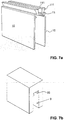
- FIGS. 7a and 7b is a Schwalbenschanzitati shown.
- the door groove 9 according FIG. 7b has in the upper part of a dovetail groove 95 and the seal housing according to Figure 7a has a correspondingly shaped sliding block 111 on the web 11.
- FIGS. 8a to 8d another embodiment is shown.
- the stop element and the Hinfallfalltikelement is now formed by the same component, namely a trained as a resilient claw leaf spring 6.
- FIG. 8a a portion of the seal housing 1 is shown.
- it has a substantially U-shaped cross section with an upper web 11 and two lateral limbs 10 adjoining one another, preferably spaced parallel to one another. It in turn preferably has the same cross section over its entire length.
- the seal housing 1 is also in turn preferably extruded profile, in particular made of aluminum.
- the seal housing 1 has on both sides and preferably over its entire length extending upper and lower U-shaped grooves 112, 104.
- the upper receiving grooves 112 are formed by a broadening and pulling down the web 11.
- the lower grooves 104 are formed on the legs 10 accordingly.
- the upper receiving grooves 112 are open at the bottom, the upper receiving grooves 104 upwards so that they are executed open to each other executed executed.
- At least one leg 10 is at least one, in particular on each side of the seal each two spring elements 6 are present.
- such spring elements 6 are present at least in the region of the front ends.
- the spring element 6 is in FIG. 8d good to see. It has a leaf spring body 60, which is bent and thus formed biased. An edge of the leaf spring body 60 is jagged and formed as a claw 62. On two opposite sides of the leaf spring body 60 tabs or tabs 61, which protrude on two opposite sides of the leaf spring body 60. Preferably, exactly two such lugs 61 are present on both sides.
- the spring element 6 can now be inserted between the upper and lower receiving groove 112, 104 by the lugs 61 are pushed into the grooves.
- FIG. 8c is shown, while the leaf spring body 60 projects hump-shaped between these two attachment points of the outermost surface of the seal housing 1.
- the claw 62 is not available, so that the risk of accidents is reduced.
- FIG. 8c is shown on one side only a spring 6.
- the corresponding spring on the opposite side can be arranged at the same height or offset from it.
- the provided with these spring elements 6 seal housing 1 can now be inserted into a known groove with a U-shaped cross-section.
- the spring element 6 serves as a fastening means for resilient engagement with a side wall of the door groove. Again, no tools or screws, nails or the like are necessary for fixing the seal in the groove.
- This seal is particularly suitable for wooden doors. It is advantageous that this seal can be removed easily and without tools.
- the seal can be assembled easily and quickly.
- the assembly of the leaf spring 6 also requires no tools.
- leaf spring does not affect the other shape of the seal, in particular the sealing strip and the lowering mechanism. It is thus possible to convert known seals with little adaptation of the seal housing accordingly.
- the sealing housing described here can be used in all embodiments with lowerable, in particular automatically lowerable sealing strips, but also with sliding seals.
- the above-described grooves and sealing housing, stop elements and spring elements can be virtually any combination.
- the groove according to Figure 1c with a stop according to FIG. 3a or 4 provided.
- the seal housing according to the FIGS. 5a . 6a . 7a and 8a with a stop element according to the FIGS. 1a and 2 be provided.
- FIGS. 9a and 9b a further embodiment, which is suitable but especially not exclusively for wooden doors.
- the door T in turn has a downwardly open U-shaped groove 9 with plane-parallel side walls.
- a receiving groove 96 is provided in both side walls, which preferably extends over the entire width of the door.
- the two grooves 96 extend at the same and constant height.
- the seal housing 1 has on its side walls outwardly projecting ribs or sliding blocks 105. As a result, the seal 1 can be pushed laterally into the groove 9 of the door and is held in the receiving groove 96 in a form-fitting manner in its position of use.
- the groove 9 can turn off and not be completely continuous, so that it forms an upper one-sided stop for the seal.
- the seal can also be fixed on one or both sides by known means, in particular fastening means.
- the use position is in FIG. 9b recognizable.
- the sealing strip 3 is directed with the sealing element down to the ground and is either, as shown here, raised or lowered.
- the seal 1 can also be held in the groove 9 in the reverse position or orientation. This is in FIG. 9a shown. This situation corresponds to a storage and transport situation.
- the seal is preferably secured by means of an adhesive strip or other suitable means on one or both end faces from falling out of the door.
- the position of the receiving groove 96 should be selected so that the seal in both layers, ie in the transport and in the position of use, does not protrude from the bottom of the door.
- This method for storage and transport of the seal in a transport position on or within the door has several advantages.
- the seal can already be introduced into the door by the door manufacturer and thus delivered together with the door to the construction site.
- the insertion into the transport position can be done automatically and automatically.
- the seal does not need to be stored and transported separately. It is optimally protected during storage and transport as the soft sealing element is directed upwards.
- gaskets can also be provided with corresponding groove stones.
- the groove of the door with a sliding block and the seal can be provided with a corresponding receiving groove.
- more than one groove can be arranged one above the other.
- the seal can also in the embodiments according to the FIGS. 1a to 1c and 3a, 3b and 4 (with stepped groove) are held in a different position of use transport position. Again, the seal can easily in 180 ° rotated orientation with upward Sealing element are held in the groove.
- the inventive door and door seal have the advantage that the seal can be mounted without tools in the door groove, that it is easy and again removable without tools and that they are simple.
Landscapes
- Engineering & Computer Science (AREA)
- Civil Engineering (AREA)
- Structural Engineering (AREA)
- Specific Sealing Or Ventilating Devices For Doors And Windows (AREA)
- Sealing Devices (AREA)
Claims (5)
- Joint d'étanchéité de porte comprenant un boîtier de joint d'étanchéité (1), un élément d'étanchéité retenu dans celui-ci et des moyens de fixation pour la fixation du boîtier de joint d'étanchéité dans une rainure de porte (9), le boîtier de joint d'étanchéité (1) présentant une nervure (11) et deux branches (10) disposées latéralement sur celle-ci, et le moyen de fixation présentant au moins un élément de ressort (6) pour le support élastique contre une paroi latérale de la rainure de porte (9),
caractérisé en ce qu'au moins l'un de ces éléments de ressort (6) est disposé sur une surface extérieure respective des branches (10) du boîtier de joint d'étanchéité (1). - Joint d'étanchéité de porte selon la revendication 1, dans lequel l'élément de ressort est un ressort à lame (6).
- Joint d'étanchéité de porte selon la revendication 2, dans lequel l'élément de ressort (6) est réalisé sous forme de griffe (62) de manière à s'accrocher fixement dans une paroi latérale de la rainure de porte (9) pendant l'insertion du boîtier de joint d'étanchéité (1) dans cette rainure de porte (9).
- Joint d'étanchéité de porte selon l'une quelconque des revendications 1 à 3, dans lequel le boîtier de joint d'étanchéité (1) présente, sur les côtés extérieurs des deux branches (10), des rainures de réception en forme de U supérieure et inférieure (112, 104), lesquelles rainures sont réalisées de manière ouverte l'une vers l'autre et dans lesquelles l'élément de ressort (6) peut être inséré.
- Joint d'étanchéité de porte selon la revendication 4, dans lequel l'élément de ressort (6) présente un corps de base (60) depuis lequel des ergots (61) font saillie sur deux côtés opposés, lesquels ergots sont retenus dans les rainures de réception supérieure et inférieure (112, 104).
Applications Claiming Priority (2)
| Application Number | Priority Date | Filing Date | Title |
|---|---|---|---|
| CH17052007 | 2007-11-02 | ||
| CH6152008 | 2008-04-18 |
Publications (3)
| Publication Number | Publication Date |
|---|---|
| EP2055888A2 EP2055888A2 (fr) | 2009-05-06 |
| EP2055888A3 EP2055888A3 (fr) | 2014-01-01 |
| EP2055888B1 true EP2055888B1 (fr) | 2018-02-28 |
Family
ID=40344804
Family Applications (1)
| Application Number | Title | Priority Date | Filing Date |
|---|---|---|---|
| EP08405270.3A Not-in-force EP2055888B1 (fr) | 2007-11-02 | 2008-10-27 | Porte dotée d'un joint et joint de porte correspondant |
Country Status (1)
| Country | Link |
|---|---|
| EP (1) | EP2055888B1 (fr) |
Cited By (1)
| Publication number | Priority date | Publication date | Assignee | Title |
|---|---|---|---|---|
| EP4105431A2 (fr) | 2021-05-25 | 2022-12-21 | ASSA ABLOY (Schweiz) AG | Agencement d'étanchéité pour une porte ou une fenêtre |
Families Citing this family (7)
| Publication number | Priority date | Publication date | Assignee | Title |
|---|---|---|---|---|
| DE202010010057U1 (de) | 2010-07-09 | 2010-10-28 | Planet Gdz Ag | Türdichtungssystem mit Befestigungselement |
| DE102013109301A1 (de) | 2013-08-28 | 2015-03-05 | Athmer Ohg | Anschlagwinkel |
| DE202014101304U1 (de) * | 2014-01-15 | 2014-05-08 | Athmer Ohg | Türdichtungssystem |
| CN104775729B (zh) * | 2014-03-21 | 2018-11-09 | 阿特玛无限公司 | 门密封装置 |
| NL2012920B1 (nl) * | 2014-05-30 | 2016-06-09 | Elton Bv | Deurafdichting, deur met deurafdichting en werkwijze voor het vervaardigen daarvan. |
| IT201700010384A1 (it) * | 2017-01-31 | 2018-07-31 | Luca Geron | Dispositivo paraspifferi ad ancoraggio facilitato |
| EP3543452A1 (fr) | 2018-03-19 | 2019-09-25 | Planet GDZ AG | Joint d'étanchéité de porte pourvu d'un élément de fixation |
Family Cites Families (13)
| Publication number | Priority date | Publication date | Assignee | Title |
|---|---|---|---|---|
| DE147567C (fr) * | ||||
| BE519910A (fr) * | ||||
| US2066188A (en) * | 1935-08-17 | 1936-12-29 | Reese Metal Weather Strip Co | Weather strip |
| FR836214A (fr) * | 1937-04-08 | 1939-01-12 | Perfectionnements aux dispositifs de bourrelet pour portes et fermetures similaires | |
| DE815538C (de) | 1949-07-09 | 1951-10-01 | Curt B Bruns | Dichtungseinrichtung fuer Tueren |
| US3871133A (en) | 1974-01-14 | 1975-03-18 | Jr Chester W Ellingson | Door bottom weather sealing structure |
| FI88332C (fi) | 1988-04-19 | 1993-04-26 | Planet Matthias Jaggi | Taetningsanordning foer en troeskelloes doerr |
| GB2231360B (en) | 1989-05-09 | 1993-07-28 | Kleeneze Limited | Draught sealing devices for doors |
| DE9301241U1 (de) | 1993-01-29 | 1993-04-22 | Fa. F. Athmer, 5760 Arnsberg | Stahltür mit einer bodenseitigen automatischen Dichtungsvorrichtung |
| DE20002108U1 (de) | 2000-02-07 | 2000-04-20 | PLANET GDZ AG, Nürensdorf | Türflügel für eine schwellenlose Türe |
| IT1315306B1 (it) | 2000-03-31 | 2003-02-10 | Luigi Geron | Dispositivo di fissaggio per apparecchi paraspifferi automatici edapparecchio paraspifferi incorporante tale dispositivo |
| EP1486639B1 (fr) | 2003-06-10 | 2012-04-18 | Planet GDZ AG | Joint d'étanchéité descendant pour porte |
| DE102005047854A1 (de) | 2005-10-05 | 2007-04-12 | Fa. F. Athmer | Dichtungen, Verfahren und Vorrichtung zum Montieren der Dichtungen und Türen mit den Dichtungen |
-
2008
- 2008-10-27 EP EP08405270.3A patent/EP2055888B1/fr not_active Not-in-force
Non-Patent Citations (1)
| Title |
|---|
| None * |
Cited By (1)
| Publication number | Priority date | Publication date | Assignee | Title |
|---|---|---|---|---|
| EP4105431A2 (fr) | 2021-05-25 | 2022-12-21 | ASSA ABLOY (Schweiz) AG | Agencement d'étanchéité pour une porte ou une fenêtre |
Also Published As
| Publication number | Publication date |
|---|---|
| EP2055888A2 (fr) | 2009-05-06 |
| EP2055888A3 (fr) | 2014-01-01 |
Similar Documents
| Publication | Publication Date | Title |
|---|---|---|
| EP2055888B1 (fr) | Porte dotée d'un joint et joint de porte correspondant | |
| DE69705662T2 (de) | Rollvorrichtung für Schiebetüren, Fenster oder ähnliches | |
| DE69803296T2 (de) | Halterung für eine abschirmvorrichtung | |
| DE1484078A1 (de) | Trennwand | |
| EP3423658B1 (fr) | Porte, fenêtre ou élément de façade | |
| AT511046B1 (de) | Rahmensystem eines partikelschutzgitters | |
| DE4445793C1 (de) | Fenster, Tür od. ähnlicher Öffnungsverschluß | |
| EP0653012B1 (fr) | Volet roulant du type jalousie | |
| DE102015108275A1 (de) | Eckblende für Hohlprofil-Eckverbinder, Eckverbinder, Eckverbinder-Bausatz, Rahmenstruktur und Schutzgitter | |
| DE3912136C2 (fr) | ||
| EP2055887A2 (fr) | Procédé de stockage ou de transport d'un joint de porte d'un battant de porte | |
| EP3241974A1 (fr) | Système pour un joint d'étanchéité, en particulier pour un joint de seuil ou pour un joint de portes s'abaissant automatiquement | |
| DE102010049782A1 (de) | Rahmensystem für ein Schutzgitter | |
| AT12786U1 (de) | Türdichtungssystem | |
| DE102017107910A1 (de) | Möbel mit einem an einem Laufprofil verfahrbaren Schiebeelement und einer Führungseinrichtung | |
| DE202006004608U1 (de) | Verbindungsanordnung für einen Lamellen aufweisenden Raffstore o.dgl. | |
| DE102006059750B4 (de) | Möbelverkettungselement und damit ausgestattetes Möbel | |
| EP1205128B1 (fr) | Etagère | |
| EP2295684B1 (fr) | Butée pour une fenêtre, une porte ou analogue, ainsi que fenêtre, porte ou analogue dotée d'une telle butée | |
| AT500181B1 (de) | Tür- oder fensterbeschlag | |
| DE202008015077U1 (de) | Adapter zur Befestigung von Solarmodulen, mit Adapter befestigte Solarmodule und Werkzeug zum Lösen der Befestigung | |
| EP3916191A1 (fr) | Système de fixation d'une unité fonctionnelle d'un dispositif d'ombrage de l'ouverture d'un bâtiment | |
| AT503531A1 (de) | Nivellierungsvorrichtung | |
| DE19734647B4 (de) | Beschlagteil an einem Flügel oder einem festen Rahmen eines Fensters, einer Tür od. dgl. | |
| DE4406817A1 (de) | Fahrzeugeinrichtung |
Legal Events
| Date | Code | Title | Description |
|---|---|---|---|
| PUAI | Public reference made under article 153(3) epc to a published international application that has entered the european phase |
Free format text: ORIGINAL CODE: 0009012 |
|
| AK | Designated contracting states |
Kind code of ref document: A2 Designated state(s): AT BE BG CH CY CZ DE DK EE ES FI FR GB GR HR HU IE IS IT LI LT LU LV MC MT NL NO PL PT RO SE SI SK TR |
|
| AX | Request for extension of the european patent |
Extension state: AL BA MK RS |
|
| RIN1 | Information on inventor provided before grant (corrected) |
Inventor name: DINTHEER, ANDREAS |
|
| PUAL | Search report despatched |
Free format text: ORIGINAL CODE: 0009013 |
|
| AK | Designated contracting states |
Kind code of ref document: A3 Designated state(s): AT BE BG CH CY CZ DE DK EE ES FI FR GB GR HR HU IE IS IT LI LT LU LV MC MT NL NO PL PT RO SE SI SK TR |
|
| AX | Request for extension of the european patent |
Extension state: AL BA MK RS |
|
| RIC1 | Information provided on ipc code assigned before grant |
Ipc: E06B 7/215 20060101AFI20131126BHEP |
|
| RAP1 | Party data changed (applicant data changed or rights of an application transferred) |
Owner name: PLANET GDZ AG |
|
| 17P | Request for examination filed |
Effective date: 20140630 |
|
| RBV | Designated contracting states (corrected) |
Designated state(s): AT BE BG CH CY CZ DE DK EE ES FI FR GB GR HR HU IE IS IT LI LT LU LV MC MT NL NO PL PT RO SE SI SK TR |
|
| AKX | Designation fees paid |
Designated state(s): AT BE BG CH CY CZ DE DK EE ES FI FR GB GR HR HU IE IS IT LI LT LU LV MC MT NL NO PL PT RO SE SI SK TR |
|
| 17Q | First examination report despatched |
Effective date: 20161021 |
|
| GRAP | Despatch of communication of intention to grant a patent |
Free format text: ORIGINAL CODE: EPIDOSNIGR1 |
|
| INTG | Intention to grant announced |
Effective date: 20170926 |
|
| GRAS | Grant fee paid |
Free format text: ORIGINAL CODE: EPIDOSNIGR3 |
|
| GRAA | (expected) grant |
Free format text: ORIGINAL CODE: 0009210 |
|
| AK | Designated contracting states |
Kind code of ref document: B1 Designated state(s): AT BE BG CH CY CZ DE DK EE ES FI FR GB GR HR HU IE IS IT LI LT LU LV MC MT NL NO PL PT RO SE SI SK TR |
|
| REG | Reference to a national code |
Ref country code: GB Ref legal event code: FG4D Free format text: NOT ENGLISH Ref country code: CH Ref legal event code: EP |
|
| REG | Reference to a national code |
Ref country code: AT Ref legal event code: REF Ref document number: 974342 Country of ref document: AT Kind code of ref document: T Effective date: 20180315 |
|
| REG | Reference to a national code |
Ref country code: IE Ref legal event code: FG4D Free format text: LANGUAGE OF EP DOCUMENT: GERMAN |
|
| REG | Reference to a national code |
Ref country code: DE Ref legal event code: R096 Ref document number: 502008015919 Country of ref document: DE |
|
| REG | Reference to a national code |
Ref country code: CH Ref legal event code: NV Representative=s name: ISLER AND PEDRAZZINI AG, CH |
|
| REG | Reference to a national code |
Ref country code: NL Ref legal event code: FP |
|
| REG | Reference to a national code |
Ref country code: LT Ref legal event code: MG4D |
|
| PG25 | Lapsed in a contracting state [announced via postgrant information from national office to epo] |
Ref country code: HR Free format text: LAPSE BECAUSE OF FAILURE TO SUBMIT A TRANSLATION OF THE DESCRIPTION OR TO PAY THE FEE WITHIN THE PRESCRIBED TIME-LIMIT Effective date: 20180228 Ref country code: LT Free format text: LAPSE BECAUSE OF FAILURE TO SUBMIT A TRANSLATION OF THE DESCRIPTION OR TO PAY THE FEE WITHIN THE PRESCRIBED TIME-LIMIT Effective date: 20180228 Ref country code: ES Free format text: LAPSE BECAUSE OF FAILURE TO SUBMIT A TRANSLATION OF THE DESCRIPTION OR TO PAY THE FEE WITHIN THE PRESCRIBED TIME-LIMIT Effective date: 20180228 Ref country code: CY Free format text: LAPSE BECAUSE OF FAILURE TO SUBMIT A TRANSLATION OF THE DESCRIPTION OR TO PAY THE FEE WITHIN THE PRESCRIBED TIME-LIMIT Effective date: 20180228 Ref country code: NO Free format text: LAPSE BECAUSE OF FAILURE TO SUBMIT A TRANSLATION OF THE DESCRIPTION OR TO PAY THE FEE WITHIN THE PRESCRIBED TIME-LIMIT Effective date: 20180528 Ref country code: FI Free format text: LAPSE BECAUSE OF FAILURE TO SUBMIT A TRANSLATION OF THE DESCRIPTION OR TO PAY THE FEE WITHIN THE PRESCRIBED TIME-LIMIT Effective date: 20180228 |
|
| PG25 | Lapsed in a contracting state [announced via postgrant information from national office to epo] |
Ref country code: LV Free format text: LAPSE BECAUSE OF FAILURE TO SUBMIT A TRANSLATION OF THE DESCRIPTION OR TO PAY THE FEE WITHIN THE PRESCRIBED TIME-LIMIT Effective date: 20180228 Ref country code: BG Free format text: LAPSE BECAUSE OF FAILURE TO SUBMIT A TRANSLATION OF THE DESCRIPTION OR TO PAY THE FEE WITHIN THE PRESCRIBED TIME-LIMIT Effective date: 20180528 Ref country code: GR Free format text: LAPSE BECAUSE OF FAILURE TO SUBMIT A TRANSLATION OF THE DESCRIPTION OR TO PAY THE FEE WITHIN THE PRESCRIBED TIME-LIMIT Effective date: 20180529 Ref country code: SE Free format text: LAPSE BECAUSE OF FAILURE TO SUBMIT A TRANSLATION OF THE DESCRIPTION OR TO PAY THE FEE WITHIN THE PRESCRIBED TIME-LIMIT Effective date: 20180228 |
|
| PG25 | Lapsed in a contracting state [announced via postgrant information from national office to epo] |
Ref country code: MT Free format text: LAPSE BECAUSE OF FAILURE TO SUBMIT A TRANSLATION OF THE DESCRIPTION OR TO PAY THE FEE WITHIN THE PRESCRIBED TIME-LIMIT Effective date: 20180228 |
|
| REG | Reference to a national code |
Ref country code: FR Ref legal event code: PLFP Year of fee payment: 11 |
|
| PG25 | Lapsed in a contracting state [announced via postgrant information from national office to epo] |
Ref country code: RO Free format text: LAPSE BECAUSE OF FAILURE TO SUBMIT A TRANSLATION OF THE DESCRIPTION OR TO PAY THE FEE WITHIN THE PRESCRIBED TIME-LIMIT Effective date: 20180228 Ref country code: PL Free format text: LAPSE BECAUSE OF FAILURE TO SUBMIT A TRANSLATION OF THE DESCRIPTION OR TO PAY THE FEE WITHIN THE PRESCRIBED TIME-LIMIT Effective date: 20180228 Ref country code: EE Free format text: LAPSE BECAUSE OF FAILURE TO SUBMIT A TRANSLATION OF THE DESCRIPTION OR TO PAY THE FEE WITHIN THE PRESCRIBED TIME-LIMIT Effective date: 20180228 |
|
| REG | Reference to a national code |
Ref country code: DE Ref legal event code: R097 Ref document number: 502008015919 Country of ref document: DE |
|
| PG25 | Lapsed in a contracting state [announced via postgrant information from national office to epo] |
Ref country code: SK Free format text: LAPSE BECAUSE OF FAILURE TO SUBMIT A TRANSLATION OF THE DESCRIPTION OR TO PAY THE FEE WITHIN THE PRESCRIBED TIME-LIMIT Effective date: 20180228 Ref country code: DK Free format text: LAPSE BECAUSE OF FAILURE TO SUBMIT A TRANSLATION OF THE DESCRIPTION OR TO PAY THE FEE WITHIN THE PRESCRIBED TIME-LIMIT Effective date: 20180228 Ref country code: CZ Free format text: LAPSE BECAUSE OF FAILURE TO SUBMIT A TRANSLATION OF THE DESCRIPTION OR TO PAY THE FEE WITHIN THE PRESCRIBED TIME-LIMIT Effective date: 20180228 |
|
| PLBE | No opposition filed within time limit |
Free format text: ORIGINAL CODE: 0009261 |
|
| STAA | Information on the status of an ep patent application or granted ep patent |
Free format text: STATUS: NO OPPOSITION FILED WITHIN TIME LIMIT |
|
| 26N | No opposition filed |
Effective date: 20181129 |
|
| PG25 | Lapsed in a contracting state [announced via postgrant information from national office to epo] |
Ref country code: SI Free format text: LAPSE BECAUSE OF FAILURE TO SUBMIT A TRANSLATION OF THE DESCRIPTION OR TO PAY THE FEE WITHIN THE PRESCRIBED TIME-LIMIT Effective date: 20180228 |
|
| REG | Reference to a national code |
Ref country code: BE Ref legal event code: MM Effective date: 20181031 |
|
| PG25 | Lapsed in a contracting state [announced via postgrant information from national office to epo] |
Ref country code: MC Free format text: LAPSE BECAUSE OF FAILURE TO SUBMIT A TRANSLATION OF THE DESCRIPTION OR TO PAY THE FEE WITHIN THE PRESCRIBED TIME-LIMIT Effective date: 20180228 Ref country code: LU Free format text: LAPSE BECAUSE OF NON-PAYMENT OF DUE FEES Effective date: 20181027 |
|
| REG | Reference to a national code |
Ref country code: IE Ref legal event code: MM4A |
|
| REG | Reference to a national code |
Ref country code: DE Ref legal event code: R082 Ref document number: 502008015919 Country of ref document: DE Representative=s name: HOEGER, STELLRECHT & PARTNER PATENTANWAELTE MB, DE |
|
| PG25 | Lapsed in a contracting state [announced via postgrant information from national office to epo] |
Ref country code: BE Free format text: LAPSE BECAUSE OF NON-PAYMENT OF DUE FEES Effective date: 20181031 |
|
| PG25 | Lapsed in a contracting state [announced via postgrant information from national office to epo] |
Ref country code: IE Free format text: LAPSE BECAUSE OF NON-PAYMENT OF DUE FEES Effective date: 20181027 |
|
| PGFP | Annual fee paid to national office [announced via postgrant information from national office to epo] |
Ref country code: NL Payment date: 20191021 Year of fee payment: 12 |
|
| PGFP | Annual fee paid to national office [announced via postgrant information from national office to epo] |
Ref country code: FR Payment date: 20191028 Year of fee payment: 12 Ref country code: IT Payment date: 20191024 Year of fee payment: 12 |
|
| PG25 | Lapsed in a contracting state [announced via postgrant information from national office to epo] |
Ref country code: TR Free format text: LAPSE BECAUSE OF FAILURE TO SUBMIT A TRANSLATION OF THE DESCRIPTION OR TO PAY THE FEE WITHIN THE PRESCRIBED TIME-LIMIT Effective date: 20180228 |
|
| PGFP | Annual fee paid to national office [announced via postgrant information from national office to epo] |
Ref country code: AT Payment date: 20191022 Year of fee payment: 12 |
|
| PGFP | Annual fee paid to national office [announced via postgrant information from national office to epo] |
Ref country code: GB Payment date: 20191021 Year of fee payment: 12 |
|
| PG25 | Lapsed in a contracting state [announced via postgrant information from national office to epo] |
Ref country code: PT Free format text: LAPSE BECAUSE OF FAILURE TO SUBMIT A TRANSLATION OF THE DESCRIPTION OR TO PAY THE FEE WITHIN THE PRESCRIBED TIME-LIMIT Effective date: 20180228 |
|
| PG25 | Lapsed in a contracting state [announced via postgrant information from national office to epo] |
Ref country code: HU Free format text: LAPSE BECAUSE OF FAILURE TO SUBMIT A TRANSLATION OF THE DESCRIPTION OR TO PAY THE FEE WITHIN THE PRESCRIBED TIME-LIMIT; INVALID AB INITIO Effective date: 20081027 |
|
| PG25 | Lapsed in a contracting state [announced via postgrant information from national office to epo] |
Ref country code: IS Free format text: LAPSE BECAUSE OF FAILURE TO SUBMIT A TRANSLATION OF THE DESCRIPTION OR TO PAY THE FEE WITHIN THE PRESCRIBED TIME-LIMIT Effective date: 20180628 |
|
| REG | Reference to a national code |
Ref country code: NL Ref legal event code: MM Effective date: 20201101 |
|
| REG | Reference to a national code |
Ref country code: AT Ref legal event code: MM01 Ref document number: 974342 Country of ref document: AT Kind code of ref document: T Effective date: 20201027 |
|
| GBPC | Gb: european patent ceased through non-payment of renewal fee |
Effective date: 20201027 |
|
| PG25 | Lapsed in a contracting state [announced via postgrant information from national office to epo] |
Ref country code: FR Free format text: LAPSE BECAUSE OF NON-PAYMENT OF DUE FEES Effective date: 20201031 Ref country code: NL Free format text: LAPSE BECAUSE OF NON-PAYMENT OF DUE FEES Effective date: 20201101 |
|
| PG25 | Lapsed in a contracting state [announced via postgrant information from national office to epo] |
Ref country code: GB Free format text: LAPSE BECAUSE OF NON-PAYMENT OF DUE FEES Effective date: 20201027 Ref country code: AT Free format text: LAPSE BECAUSE OF NON-PAYMENT OF DUE FEES Effective date: 20201027 |
|
| PG25 | Lapsed in a contracting state [announced via postgrant information from national office to epo] |
Ref country code: IT Free format text: LAPSE BECAUSE OF NON-PAYMENT OF DUE FEES Effective date: 20201027 |
|
| PGFP | Annual fee paid to national office [announced via postgrant information from national office to epo] |
Ref country code: CH Payment date: 20210928 Year of fee payment: 14 |
|
| PGFP | Annual fee paid to national office [announced via postgrant information from national office to epo] |
Ref country code: DE Payment date: 20210914 Year of fee payment: 14 |
|
| REG | Reference to a national code |
Ref country code: DE Ref legal event code: R119 Ref document number: 502008015919 Country of ref document: DE |
|
| REG | Reference to a national code |
Ref country code: CH Ref legal event code: PL |
|
| PG25 | Lapsed in a contracting state [announced via postgrant information from national office to epo] |
Ref country code: LI Free format text: LAPSE BECAUSE OF NON-PAYMENT OF DUE FEES Effective date: 20221031 Ref country code: DE Free format text: LAPSE BECAUSE OF NON-PAYMENT OF DUE FEES Effective date: 20230503 Ref country code: CH Free format text: LAPSE BECAUSE OF NON-PAYMENT OF DUE FEES Effective date: 20221031 |