EP2055805B1 - Verfahren und Vorrichtung zur Entfettung - Google Patents
Verfahren und Vorrichtung zur Entfettung Download PDFInfo
- Publication number
- EP2055805B1 EP2055805B1 EP20080018915 EP08018915A EP2055805B1 EP 2055805 B1 EP2055805 B1 EP 2055805B1 EP 20080018915 EP20080018915 EP 20080018915 EP 08018915 A EP08018915 A EP 08018915A EP 2055805 B1 EP2055805 B1 EP 2055805B1
- Authority
- EP
- European Patent Office
- Prior art keywords
- aqueous solution
- degreasing
- joint portion
- water
- surfactant
- Prior art date
- Legal status (The legal status is an assumption and is not a legal conclusion. Google has not performed a legal analysis and makes no representation as to the accuracy of the status listed.)
- Ceased
Links
- 238000005238 degreasing Methods 0.000 title claims description 126
- 238000000034 method Methods 0.000 title claims description 25
- 239000007864 aqueous solution Substances 0.000 claims description 149
- XLYOFNOQVPJJNP-UHFFFAOYSA-N water Substances O XLYOFNOQVPJJNP-UHFFFAOYSA-N 0.000 claims description 139
- 239000007788 liquid Substances 0.000 claims description 111
- 239000011248 coating agent Substances 0.000 claims description 86
- 238000000576 coating method Methods 0.000 claims description 86
- 238000004070 electrodeposition Methods 0.000 claims description 86
- 239000004094 surface-active agent Substances 0.000 claims description 60
- 229910052751 metal Inorganic materials 0.000 claims description 29
- 239000002184 metal Substances 0.000 claims description 29
- 150000003839 salts Chemical class 0.000 claims description 26
- 229910021645 metal ion Inorganic materials 0.000 claims description 22
- 238000005237 degreasing agent Methods 0.000 claims description 21
- 239000007853 buffer solution Substances 0.000 claims description 20
- 239000013527 degreasing agent Substances 0.000 claims description 20
- 239000002683 reaction inhibitor Substances 0.000 claims description 13
- 229910052736 halogen Inorganic materials 0.000 claims description 11
- 150000002367 halogens Chemical class 0.000 claims description 11
- 229910052729 chemical element Inorganic materials 0.000 claims description 9
- 239000000126 substance Substances 0.000 description 42
- 239000000463 material Substances 0.000 description 39
- 238000005406 washing Methods 0.000 description 35
- 230000007797 corrosion Effects 0.000 description 34
- 238000005260 corrosion Methods 0.000 description 34
- 230000002776 aggregation Effects 0.000 description 32
- 238000004220 aggregation Methods 0.000 description 32
- 239000007787 solid Substances 0.000 description 32
- 238000007747 plating Methods 0.000 description 20
- 238000012360 testing method Methods 0.000 description 17
- 125000003178 carboxy group Chemical group [H]OC(*)=O 0.000 description 15
- XEEYBQQBJWHFJM-UHFFFAOYSA-N Iron Chemical compound [Fe] XEEYBQQBJWHFJM-UHFFFAOYSA-N 0.000 description 14
- 238000002474 experimental method Methods 0.000 description 14
- 239000008213 purified water Substances 0.000 description 14
- 239000011701 zinc Substances 0.000 description 14
- HCHKCACWOHOZIP-UHFFFAOYSA-N Zinc Chemical compound [Zn] HCHKCACWOHOZIP-UHFFFAOYSA-N 0.000 description 13
- 238000004090 dissolution Methods 0.000 description 13
- 229910052725 zinc Inorganic materials 0.000 description 13
- 230000004048 modification Effects 0.000 description 12
- 238000012986 modification Methods 0.000 description 12
- CDBYLPFSWZWCQE-UHFFFAOYSA-L Sodium Carbonate Chemical compound [Na+].[Na+].[O-]C([O-])=O CDBYLPFSWZWCQE-UHFFFAOYSA-L 0.000 description 10
- UIIMBOGNXHQVGW-UHFFFAOYSA-M Sodium bicarbonate Chemical compound [Na+].OC([O-])=O UIIMBOGNXHQVGW-UHFFFAOYSA-M 0.000 description 10
- 238000004140 cleaning Methods 0.000 description 9
- 238000011084 recovery Methods 0.000 description 9
- 239000000243 solution Substances 0.000 description 9
- 238000010790 dilution Methods 0.000 description 8
- 239000012895 dilution Substances 0.000 description 8
- 229910052911 sodium silicate Inorganic materials 0.000 description 8
- ZAMOUSCENKQFHK-UHFFFAOYSA-N Chlorine atom Chemical compound [Cl] ZAMOUSCENKQFHK-UHFFFAOYSA-N 0.000 description 7
- 229910003641 H2SiO3 Inorganic materials 0.000 description 7
- 229910020489 SiO3 Inorganic materials 0.000 description 7
- 238000006243 chemical reaction Methods 0.000 description 7
- 229910052801 chlorine Inorganic materials 0.000 description 7
- 239000000460 chlorine Substances 0.000 description 7
- 238000010586 diagram Methods 0.000 description 7
- 239000000428 dust Substances 0.000 description 7
- 230000000694 effects Effects 0.000 description 7
- 238000001704 evaporation Methods 0.000 description 7
- 230000008020 evaporation Effects 0.000 description 7
- 230000007246 mechanism Effects 0.000 description 7
- QTBSBXVTEAMEQO-UHFFFAOYSA-N Acetic acid Chemical compound CC(O)=O QTBSBXVTEAMEQO-UHFFFAOYSA-N 0.000 description 6
- VEXZGXHMUGYJMC-UHFFFAOYSA-M Chloride anion Chemical compound [Cl-] VEXZGXHMUGYJMC-UHFFFAOYSA-M 0.000 description 6
- 229910001335 Galvanized steel Inorganic materials 0.000 description 6
- 230000007423 decrease Effects 0.000 description 6
- 239000008397 galvanized steel Substances 0.000 description 6
- GRYLNZFGIOXLOG-UHFFFAOYSA-N Nitric acid Chemical compound O[N+]([O-])=O GRYLNZFGIOXLOG-UHFFFAOYSA-N 0.000 description 5
- 230000008595 infiltration Effects 0.000 description 5
- 238000001764 infiltration Methods 0.000 description 5
- 229910017604 nitric acid Inorganic materials 0.000 description 5
- 229910000030 sodium bicarbonate Inorganic materials 0.000 description 5
- 229910000029 sodium carbonate Inorganic materials 0.000 description 5
- 238000003466 welding Methods 0.000 description 5
- 239000011347 resin Substances 0.000 description 4
- 229920005989 resin Polymers 0.000 description 4
- 229910019142 PO4 Inorganic materials 0.000 description 3
- 239000002253 acid Substances 0.000 description 3
- 239000003795 chemical substances by application Substances 0.000 description 3
- KRKNYBCHXYNGOX-UHFFFAOYSA-N citric acid Chemical compound OC(=O)CC(O)(C(O)=O)CC(O)=O KRKNYBCHXYNGOX-UHFFFAOYSA-N 0.000 description 3
- 238000009833 condensation Methods 0.000 description 3
- 230000005494 condensation Effects 0.000 description 3
- JEIPFZHSYJVQDO-UHFFFAOYSA-N iron(III) oxide Inorganic materials O=[Fe]O[Fe]=O JEIPFZHSYJVQDO-UHFFFAOYSA-N 0.000 description 3
- 238000010979 pH adjustment Methods 0.000 description 3
- NBIIXXVUZAFLBC-UHFFFAOYSA-K phosphate Chemical compound [O-]P([O-])([O-])=O NBIIXXVUZAFLBC-UHFFFAOYSA-K 0.000 description 3
- 239000010452 phosphate Substances 0.000 description 3
- 238000002203 pretreatment Methods 0.000 description 3
- 238000003908 quality control method Methods 0.000 description 3
- 229910001415 sodium ion Inorganic materials 0.000 description 3
- 239000007921 spray Substances 0.000 description 3
- NBIIXXVUZAFLBC-UHFFFAOYSA-N Phosphoric acid Chemical compound OP(O)(O)=O NBIIXXVUZAFLBC-UHFFFAOYSA-N 0.000 description 2
- VYPSYNLAJGMNEJ-UHFFFAOYSA-N Silicium dioxide Chemical compound O=[Si]=O VYPSYNLAJGMNEJ-UHFFFAOYSA-N 0.000 description 2
- PTFCDOFLOPIGGS-UHFFFAOYSA-N Zinc dication Chemical compound [Zn+2] PTFCDOFLOPIGGS-UHFFFAOYSA-N 0.000 description 2
- 229910052782 aluminium Inorganic materials 0.000 description 2
- -1 aluminum ion Chemical class 0.000 description 2
- 230000003139 buffering effect Effects 0.000 description 2
- 125000002091 cationic group Chemical group 0.000 description 2
- 239000002738 chelating agent Substances 0.000 description 2
- 150000001875 compounds Chemical class 0.000 description 2
- 230000003750 conditioning effect Effects 0.000 description 2
- 230000003247 decreasing effect Effects 0.000 description 2
- XLYOFNOQVPJJNP-ZSJDYOACSA-N heavy water Substances [2H]O[2H] XLYOFNOQVPJJNP-ZSJDYOACSA-N 0.000 description 2
- QWPPOHNGKGFGJK-UHFFFAOYSA-N hypochlorous acid Chemical compound ClO QWPPOHNGKGFGJK-UHFFFAOYSA-N 0.000 description 2
- 239000008235 industrial water Substances 0.000 description 2
- 150000002500 ions Chemical class 0.000 description 2
- 229910052742 iron Inorganic materials 0.000 description 2
- 229910052745 lead Inorganic materials 0.000 description 2
- 239000002736 nonionic surfactant Substances 0.000 description 2
- 239000000049 pigment Substances 0.000 description 2
- 239000000843 powder Substances 0.000 description 2
- 230000002265 prevention Effects 0.000 description 2
- RMAQACBXLXPBSY-UHFFFAOYSA-N silicic acid Chemical compound O[Si](O)(O)O RMAQACBXLXPBSY-UHFFFAOYSA-N 0.000 description 2
- 235000012239 silicon dioxide Nutrition 0.000 description 2
- 239000011734 sodium Substances 0.000 description 2
- 239000008399 tap water Substances 0.000 description 2
- 235000020679 tap water Nutrition 0.000 description 2
- QTBSBXVTEAMEQO-UHFFFAOYSA-M Acetate Chemical compound CC([O-])=O QTBSBXVTEAMEQO-UHFFFAOYSA-M 0.000 description 1
- USFZMSVCRYTOJT-UHFFFAOYSA-N Ammonium acetate Chemical compound N.CC(O)=O USFZMSVCRYTOJT-UHFFFAOYSA-N 0.000 description 1
- 239000005695 Ammonium acetate Substances 0.000 description 1
- BTBUEUYNUDRHOZ-UHFFFAOYSA-N Borate Chemical compound [O-]B([O-])[O-] BTBUEUYNUDRHOZ-UHFFFAOYSA-N 0.000 description 1
- BVKZGUZCCUSVTD-UHFFFAOYSA-L Carbonate Chemical compound [O-]C([O-])=O BVKZGUZCCUSVTD-UHFFFAOYSA-L 0.000 description 1
- KKCBUQHMOMHUOY-UHFFFAOYSA-N Na2O Inorganic materials [O-2].[Na+].[Na+] KKCBUQHMOMHUOY-UHFFFAOYSA-N 0.000 description 1
- BPQQTUXANYXVAA-UHFFFAOYSA-N Orthosilicate Chemical compound [O-][Si]([O-])([O-])[O-] BPQQTUXANYXVAA-UHFFFAOYSA-N 0.000 description 1
- VMHLLURERBWHNL-UHFFFAOYSA-M Sodium acetate Chemical compound [Na+].CC([O-])=O VMHLLURERBWHNL-UHFFFAOYSA-M 0.000 description 1
- 229910000831 Steel Inorganic materials 0.000 description 1
- FEWJPZIEWOKRBE-UHFFFAOYSA-N Tartaric acid Natural products [H+].[H+].[O-]C(=O)C(O)C(O)C([O-])=O FEWJPZIEWOKRBE-UHFFFAOYSA-N 0.000 description 1
- 239000007983 Tris buffer Substances 0.000 description 1
- ITBPIKUGMIZTJR-UHFFFAOYSA-N [bis(hydroxymethyl)amino]methanol Chemical compound OCN(CO)CO ITBPIKUGMIZTJR-UHFFFAOYSA-N 0.000 description 1
- 230000002159 abnormal effect Effects 0.000 description 1
- 230000009471 action Effects 0.000 description 1
- 239000000654 additive Substances 0.000 description 1
- 150000001447 alkali salts Chemical class 0.000 description 1
- 125000000217 alkyl group Chemical group 0.000 description 1
- 238000005275 alloying Methods 0.000 description 1
- XAGFODPZIPBFFR-UHFFFAOYSA-N aluminium Chemical compound [Al] XAGFODPZIPBFFR-UHFFFAOYSA-N 0.000 description 1
- 229910000147 aluminium phosphate Inorganic materials 0.000 description 1
- 229940043376 ammonium acetate Drugs 0.000 description 1
- 235000019257 ammonium acetate Nutrition 0.000 description 1
- 239000002585 base Substances 0.000 description 1
- 230000000903 blocking effect Effects 0.000 description 1
- KGBXLFKZBHKPEV-UHFFFAOYSA-N boric acid Chemical compound OB(O)O KGBXLFKZBHKPEV-UHFFFAOYSA-N 0.000 description 1
- 239000004327 boric acid Substances 0.000 description 1
- BVKZGUZCCUSVTD-UHFFFAOYSA-N carbonic acid Chemical compound OC(O)=O BVKZGUZCCUSVTD-UHFFFAOYSA-N 0.000 description 1
- 230000008859 change Effects 0.000 description 1
- 239000007979 citrate buffer Substances 0.000 description 1
- 238000011161 development Methods 0.000 description 1
- 238000007598 dipping method Methods 0.000 description 1
- 238000009826 distribution Methods 0.000 description 1
- 230000005611 electricity Effects 0.000 description 1
- 238000011067 equilibration Methods 0.000 description 1
- 238000011156 evaluation Methods 0.000 description 1
- 238000001914 filtration Methods 0.000 description 1
- 125000004435 hydrogen atom Chemical group [H]* 0.000 description 1
- 238000007654 immersion Methods 0.000 description 1
- 239000000203 mixture Substances 0.000 description 1
- 125000004430 oxygen atom Chemical group O* 0.000 description 1
- 239000008055 phosphate buffer solution Substances 0.000 description 1
- 239000004033 plastic Substances 0.000 description 1
- 238000002360 preparation method Methods 0.000 description 1
- 238000012545 processing Methods 0.000 description 1
- 229910052761 rare earth metal Inorganic materials 0.000 description 1
- 230000009467 reduction Effects 0.000 description 1
- 230000008439 repair process Effects 0.000 description 1
- 239000000377 silicon dioxide Substances 0.000 description 1
- 239000001632 sodium acetate Substances 0.000 description 1
- 235000017281 sodium acetate Nutrition 0.000 description 1
- 235000017557 sodium bicarbonate Nutrition 0.000 description 1
- 239000001509 sodium citrate Substances 0.000 description 1
- NLJMYIDDQXHKNR-UHFFFAOYSA-K sodium citrate Chemical compound O.O.[Na+].[Na+].[Na+].[O-]C(=O)CC(O)(CC([O-])=O)C([O-])=O NLJMYIDDQXHKNR-UHFFFAOYSA-K 0.000 description 1
- 239000001488 sodium phosphate Substances 0.000 description 1
- 229910000162 sodium phosphate Inorganic materials 0.000 description 1
- NTHWMYGWWRZVTN-UHFFFAOYSA-N sodium silicate Chemical compound [Na+].[Na+].[O-][Si]([O-])=O NTHWMYGWWRZVTN-UHFFFAOYSA-N 0.000 description 1
- 239000010959 steel Substances 0.000 description 1
- 230000008961 swelling Effects 0.000 description 1
- 239000011975 tartaric acid Substances 0.000 description 1
- 235000002906 tartaric acid Nutrition 0.000 description 1
- LENZDBCJOHFCAS-UHFFFAOYSA-N tris Chemical compound OCC(N)(CO)CO LENZDBCJOHFCAS-UHFFFAOYSA-N 0.000 description 1
- RYFMWSXOAZQYPI-UHFFFAOYSA-K trisodium phosphate Chemical compound [Na+].[Na+].[Na+].[O-]P([O-])([O-])=O RYFMWSXOAZQYPI-UHFFFAOYSA-K 0.000 description 1
- 229910021511 zinc hydroxide Inorganic materials 0.000 description 1
Images


Classifications
-
- C—CHEMISTRY; METALLURGY
- C23—COATING METALLIC MATERIAL; COATING MATERIAL WITH METALLIC MATERIAL; CHEMICAL SURFACE TREATMENT; DIFFUSION TREATMENT OF METALLIC MATERIAL; COATING BY VACUUM EVAPORATION, BY SPUTTERING, BY ION IMPLANTATION OR BY CHEMICAL VAPOUR DEPOSITION, IN GENERAL; INHIBITING CORROSION OF METALLIC MATERIAL OR INCRUSTATION IN GENERAL
- C23G—CLEANING OR DE-GREASING OF METALLIC MATERIAL BY CHEMICAL METHODS OTHER THAN ELECTROLYSIS
- C23G1/00—Cleaning or pickling metallic material with solutions or molten salts
- C23G1/14—Cleaning or pickling metallic material with solutions or molten salts with alkaline solutions
-
- B—PERFORMING OPERATIONS; TRANSPORTING
- B08—CLEANING
- B08B—CLEANING IN GENERAL; PREVENTION OF FOULING IN GENERAL
- B08B3/00—Cleaning by methods involving the use or presence of liquid or steam
- B08B3/04—Cleaning involving contact with liquid
-
- B—PERFORMING OPERATIONS; TRANSPORTING
- B08—CLEANING
- B08B—CLEANING IN GENERAL; PREVENTION OF FOULING IN GENERAL
- B08B3/00—Cleaning by methods involving the use or presence of liquid or steam
- B08B3/04—Cleaning involving contact with liquid
- B08B3/08—Cleaning involving contact with liquid the liquid having chemical or dissolving effect
-
- C—CHEMISTRY; METALLURGY
- C23—COATING METALLIC MATERIAL; COATING MATERIAL WITH METALLIC MATERIAL; CHEMICAL SURFACE TREATMENT; DIFFUSION TREATMENT OF METALLIC MATERIAL; COATING BY VACUUM EVAPORATION, BY SPUTTERING, BY ION IMPLANTATION OR BY CHEMICAL VAPOUR DEPOSITION, IN GENERAL; INHIBITING CORROSION OF METALLIC MATERIAL OR INCRUSTATION IN GENERAL
- C23C—COATING METALLIC MATERIAL; COATING MATERIAL WITH METALLIC MATERIAL; SURFACE TREATMENT OF METALLIC MATERIAL BY DIFFUSION INTO THE SURFACE, BY CHEMICAL CONVERSION OR SUBSTITUTION; COATING BY VACUUM EVAPORATION, BY SPUTTERING, BY ION IMPLANTATION OR BY CHEMICAL VAPOUR DEPOSITION, IN GENERAL
- C23C22/00—Chemical surface treatment of metallic material by reaction of the surface with a reactive liquid, leaving reaction products of surface material in the coating, e.g. conversion coatings, passivation of metals
- C23C22/78—Pretreatment of the material to be coated
-
- C—CHEMISTRY; METALLURGY
- C23—COATING METALLIC MATERIAL; COATING MATERIAL WITH METALLIC MATERIAL; CHEMICAL SURFACE TREATMENT; DIFFUSION TREATMENT OF METALLIC MATERIAL; COATING BY VACUUM EVAPORATION, BY SPUTTERING, BY ION IMPLANTATION OR BY CHEMICAL VAPOUR DEPOSITION, IN GENERAL; INHIBITING CORROSION OF METALLIC MATERIAL OR INCRUSTATION IN GENERAL
- C23G—CLEANING OR DE-GREASING OF METALLIC MATERIAL BY CHEMICAL METHODS OTHER THAN ELECTROLYSIS
- C23G1/00—Cleaning or pickling metallic material with solutions or molten salts
- C23G1/14—Cleaning or pickling metallic material with solutions or molten salts with alkaline solutions
- C23G1/16—Cleaning or pickling metallic material with solutions or molten salts with alkaline solutions using inhibitors
-
- C—CHEMISTRY; METALLURGY
- C23—COATING METALLIC MATERIAL; COATING MATERIAL WITH METALLIC MATERIAL; CHEMICAL SURFACE TREATMENT; DIFFUSION TREATMENT OF METALLIC MATERIAL; COATING BY VACUUM EVAPORATION, BY SPUTTERING, BY ION IMPLANTATION OR BY CHEMICAL VAPOUR DEPOSITION, IN GENERAL; INHIBITING CORROSION OF METALLIC MATERIAL OR INCRUSTATION IN GENERAL
- C23G—CLEANING OR DE-GREASING OF METALLIC MATERIAL BY CHEMICAL METHODS OTHER THAN ELECTROLYSIS
- C23G1/00—Cleaning or pickling metallic material with solutions or molten salts
- C23G1/14—Cleaning or pickling metallic material with solutions or molten salts with alkaline solutions
- C23G1/20—Other heavy metals
-
- C—CHEMISTRY; METALLURGY
- C23—COATING METALLIC MATERIAL; COATING MATERIAL WITH METALLIC MATERIAL; CHEMICAL SURFACE TREATMENT; DIFFUSION TREATMENT OF METALLIC MATERIAL; COATING BY VACUUM EVAPORATION, BY SPUTTERING, BY ION IMPLANTATION OR BY CHEMICAL VAPOUR DEPOSITION, IN GENERAL; INHIBITING CORROSION OF METALLIC MATERIAL OR INCRUSTATION IN GENERAL
- C23G—CLEANING OR DE-GREASING OF METALLIC MATERIAL BY CHEMICAL METHODS OTHER THAN ELECTROLYSIS
- C23G1/00—Cleaning or pickling metallic material with solutions or molten salts
- C23G1/24—Cleaning or pickling metallic material with solutions or molten salts with neutral solutions
- C23G1/26—Cleaning or pickling metallic material with solutions or molten salts with neutral solutions using inhibitors
-
- C—CHEMISTRY; METALLURGY
- C25—ELECTROLYTIC OR ELECTROPHORETIC PROCESSES; APPARATUS THEREFOR
- C25D—PROCESSES FOR THE ELECTROLYTIC OR ELECTROPHORETIC PRODUCTION OF COATINGS; ELECTROFORMING; APPARATUS THEREFOR
- C25D13/00—Electrophoretic coating characterised by the process
- C25D13/20—Pretreatment
Definitions
- the present invention relates to a degreasing method.
- a pretreatment is generally performed to remove oil and dust adhered to the object which has been subjected to welding or other processings, and to form a base coating on a surface of the object, as disclosed in Japanese Laid-Open Patent Publication No. 2004-238681 .
- the pretreatment includes a hot-water washing step of immersing the object in hot water to remove dust and the like (e.g.
- electrodeposition coating is performed by immersing the object in a tank filled with a water-soluble coating material, and applying an electricity to the coating material in the tank to electrically form the object with a coating of the coating material.
- US 6,318,382 discloses a method for cleaning an electrophotographic photosensitive member which includes a cleaning step during which the circulation flow rate during dipping of the cleaning subject in a cleaning solution is different from the circulation flow rate when the cleaning subject is pulled up, and where the cleaning solution is showered on the surface of the cleaning subject when it is pulled up.
- US 2001/0025646 A1 discloses a pre-clean deluge system for cleaning automobile white bodies including a cleaning solution filtration and distribution system.
- US 4,205,101 discloses a method of treating automotive and like bodies with a pretreatment liquid in which the body is traversed with respect to a multiplicity of orifices for projection of the liquid at the body, the longitudinal axis of the body being at right angles to the direction of traverse and the major part of the liquid being projected at an angle to the longitudinal plane of symmetry of the body in the range 30°-60°.
- US 4,974,307 discloses a method of coating an automobile body which is composed of plastic parts and sheet metal parts.
- a degreasing method comprises allowing a joint portion of an object to be treated to have an aqueous solution having a pH of 5.5 to 10.0, and immersing the object in a degreasing liquid, wherein the joint portion of the object is shaped into a sac, the degreasing liquid cannot replace the aqueous solution which has entered into the sac-shaped portion, and the acqueous solution remains in the sac-shaped portion.
- the immersing is performed before an electrodeposition coating is performed, and the aqueous solution contains a metal salt and metal ions of the metal salt at a concentration of 620 ppm or smaller when the metal salt is assumed to be converted to metal ions.
- aggregation electrodeposition aggregation
- the occurrence of electrodeposition aggregation can be prevented by the aqueous solution having a pH of 10 or lower and a concentration of 620 ppm or smaller when the metal salt is assumed to be converted to metal ions. Accordingly, in addition to the prevention of the corrosion of the joint portion of the object, electrodeposition aggregation can be prevented during the electrodeposition coating.
- the aqueous solution substantially contains no surfactant. This aqueous solution can more prevent the joint portion of the object from being corroded or dissolved.
- the degreasing liquid contains a surfactant at a first surfactant concentration
- the aqueous solution contains a surfactant at a second surfactant concentration that is equal to or smaller than 1/100 of the first surfactant concentration.
- the aqueous solution containing the surfactant at the concentration equal to or smaller than 1/100 of the surfactant concentration of the degreasing liquid and having the pH of 5.5 to 10.0 Accordingly, the preparation of the aqueous solution can be easily industrialized, which thus makes it possible to industrially accomplish to maintain the corrosion resistance of the joint portion of the object.
- the aqueous solution in the joint portion can suppress the degreasing of the joint portion to thus cause a noticeable amount of oil to remain in the joint portion. The remaining oil can further prevent corrosion of the joint portion.
- the joint portion of the object is shaped into a sac. Because the joint portion of the object is a sac-shaped portion, the existence of the aqueous solution in the sac-shaped portion can assuredly prevent another liquid from coming into the sac-shaped portion even when the object is immersed in another aqueous solution. If the degreasing liquid firstly exists in the sac-shaped portion, corrosion is likely to occur. On the other hand, if the aqueous solution having the pH of 5.5 to 10.0 firstly exists in the sac-shaped portion, the corrosion resistance of the sac-shaped portion can be effectively maintained.
- the object includes a plurality of plates which are jointed with each other, and the joint portion is at an overlapped part of plates.
- the object has a structure made up of a plurality of plates and the joint portion is constructed by stacking the plates to each other, the decrease in corrosion resistance of the plates forming the joint portion due to the degreasing liquid can be assuredly prevented.
- the aqueous solution may be put into the joint portion after the plurality of plates are joined to construct the object.
- the aqueous solution is put into the joint portion after the plurality of plates are joined to construct the object, the aqueous solution can easily and reliably be present in the joint portion.
- the joint portion may be preferably immersed in the aqueous solution contained in an immersing tank to put the aqueous solution into the joint portion.
- the aqueous solution can easily and reliably be present in the joint portion.
- the aqueous solution contains a surfactant at a concentration of 50 ppm to 190 ppm.
- the aqueous solution is provided with permeating power of the surfactant in addition to the maintaining of the corrosion resistance. Accordingly, the aqueous solution can be made to smoothly enter into the joint portion owing to the permeating power of the surfactant even if an amount of oil remains in the joint portion.
- the moving distance of the object in the immersing tank can be reduced, thereby reducing the volume of the immersing tank.
- the joint portion is immersed in the aqueous solution contained in an immersing tank to put the aqueous solution into the joint portion
- the degreasing liquid contains a degreasing agent including a metal salt and a surfactant
- the aqueous solution in the immersing tank contains a part of used degreasing liquid, and has a degreasing agent concentration that is equal to or smaller than 1/10 of a degreasing agent concentration of the degreasing liquid.
- the degreasing liquid contains the degreasing agent including a metal salt and a surfactant
- the aqueous solution in the immersing tank contains the used liquid recovered after being used in the immersing of the object with the degreasing liquid
- the metal ion concentration and the surfactant concentration are attained by adjusting the degreasing agent concentration of the aqueous solution that is equal to or smaller than 1/10 of the degreasing agent concentration of the degreasing liquid. Accordingly, the desired aqueous solution can be obtained by using the used liquid, and efficient use of water can be achieved while preventing the decrease in the corrosion resistance and the occurrence of the electrodeposition aggregation in the electrodeposition coating.
- the aqueous solution may be preferably include ion-exchanged water. Because the ion-exchanged water is used for the aqueous solution, the aqueous solution does not contain chlorine ion, thereby preventing corrosion due to chlorine ion in addition to corrosion (dissolution) due to the degreasing liquid.
- the aqueous solution may preferably include a buffer solution. Because the aqueous solution includes a buffer solution, the buffer solution component remains as solid substance in the joint portion after evaporation of the water. When water comes into the joint portion later, the water dissolves the solid substance, and provides a buffering effect (prevents the pH from changing to the alkaline side by dissolution of the object). Accordingly, due to the buffering effect, the joint portion can be prevented from being corroded.
- the aqueous solution may preferably contain an anode reaction inhibitor.
- the anode reaction inhibitor remains as solid substance in the joint portion after evaporation of the water.
- the anode reaction inhibitor solid substance
- dissolves in the water captures metal ions (zinc ion, aluminum ion, and the like) eluding out from the object, and consequently forms a coating film.
- the coating film prevents further elusion of the metal ions. Accordingly, owing to this mechanism, the joint portion can be prevented from being corroded.
- the aqueous solution may preferably contain a halogen capturing chemical element.
- the halogen capturing chemical element remains as solid substance in the joint portion after evaporation of the water.
- such rare earth element solid substance
- dissolves in the water captures chlorine (halogen) contained in the entered water, and consequently forms a coating film.
- the coating film protects the object from chlorine. Accordingly, the corrosion of the joint portion due to chlorine can be prevented.
- a surface of the object may be preferably made of an amphoteric metal. Because the surface of the object is made of an amphoteric metal, even if the object has a characteristic to dissolve in the strong alkalinity, the strong alkalinity is prevented. Accordingly, the object can be prevented from being dissolved or corroded.
- a degreasing apparatus comprises an aqueous solution supplier for supplying an aqueous solution to a joint portion of the object to be immersed in a degreasing liquid, the aqueous solution having a pH of 5.5 to 10.0.
- the aqueous solution is supplied into the joint portion of the object.
- the aqueous solution prevents another liquid from entering into the joint portion. Accordingly, after the water of the aqueous solution evaporates in subsequent stages , alkaline solid substance does not remain in the joint portion. Accordingly, even if water comes into the joint portion during the use, the water in the joint portion will not have a strong alkalinity, thereby preventing the joint portion of the object from being corroded or dissolve by the water.
- the aqueous solution supplier may preferably include an immersing tank holding the aqueous solution containing a surfactant at a concentration of 50 ppm to 190 ppm.
- the aqueous solution has a permeating power of the surfactant in addition to the maintaining of the corrosion resistance. Accordingly, the aqueous solution can be made to smoothly enter into the joint portion owing to the permeating power of the surfactant even if an amount of oil remains in the joint portion.
- the moving distance of the object in the immersing tank can be reduced, thereby reducing the volume of the immersing tank.
- the aqueous solution supplier may preferably include an immersing tank holding the aqueous solution not containing a substantial amount of a surfactant.
- the aqueous solution can more prevent the joint portion of the object from being corroded or dissolved.
- an object to be treated is a vehicle body which includes a plurality of panels which are jointed with one another by means of spot welding and the like.
- the panel is made of a galvanized steel sheet which is plated with zinc.
- Zinc is an amphoteric element.
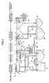
- a hot-water washing step Between a welding of jointing panels with one another to thereby a vehicle body 2 and electrodeposition coating, a hot-water washing step, an immersing (degreasing pretreatment) step, a degreasing step, a water washing step, and a chemical film forming step including a surface conditioning are performed.
- a coating pretreatment equipment 1 includes a hot-water washing tank 3, an immersing tank 4, a degreasing tank 5, first and second water washing tanks 6 and 7, and a chemical film forming tank (not shown) to accomplish the above-mentioned steps.
- the hot-water washing tank 3 is provided with a high-pressure spray 8 above its upper opening to remove dust and the like (e.g. iron powder) adhered to the vehicle body 2 by a high-pressure spray 8 which is supplied with circulating water through a supply pipe 16 by a pump 17.
- the hot-water washing tank 3 is provided with a drain pipe 11 at a bottom thereof to thereby recover the used water from the hot-water washing tank 3 to a recovery tank 12 through the drain pipe 11.
- the used water in the recovery tank 12 is sent by a pump 14 through a pipe 13 to the iron powder removing apparatus 15 where iron powder is removed from the used water to produce the circulating water.
- the circulating water is supplied from the iron powder removing apparatus 15 into the immersing tank 4 sequentially through the supply pipe 16, a branch pipe 10 and a branch pipe 18.
- the immersing tank 4 is connected at its bottom to the recovery tank 12 through a drain pipe 19, and the immersing tank 4 always holds an aqueous solution 20 at least at a certain volume which allows the vehicle body 2 to be fully immersed therein.
- the aqueous solution 20 in the immersing tank 4 is maintained at a predetermined quality which is defined as a concentration of degreasing agents of a part of the degreasing liquid which has come from the subsequent step, the degreasing agent including a surfactant and other substances.
- the aqueous solution 20 is kept to have a degreasing agent concentration which is equal to or smaller than 1/100 of a decreasing agent concentration of the degreasing liquid used in the degreasing tank 5, and to have a PH of 5.5 to 10.0, and a water temperature near the room temperature, e.g., 25° C or lower.
- the aqueous solution 20 contains a buffer solution or a buffer solution component (a weak acid salt or a weak alkali salt, e.g., ammonium acetate), an anode reaction inhibitor, and a halogen capturing chemical element capable of capturing chlorine.
- a buffer solution or the buffer solution component an acetic acid buffer solution (acetic acid and sodium acetate), a phosphate buffer solution (phosphoric acid and sodium phosphate), a citrate buffer solution (citric acid and sodium citrate), a boric acid buffer solution, a tartaric acid buffer solution, a tris buffer solution (tris(hydroxymethyl)ammonium), silica or the like is used.
- a chelating agent which captures metal ion or a phosphate pigment is used.
- halogen capturing chemical element a compound containing Pb, Ce, Bi or the like is used.
- a purified water supply source 9 is further provided to adjust the degreasing agent concentration of the aqueous solution 20 in the immersing tank 4.
- the purified water supply source 9 supplies purified water into the immersing tank 4 through a purified water supply pipe 9a, and the purified water from the purified water supply source 9 is used mainly to adjust the degreasing agent concentration through dilution.
- the purified water supply source 9 sends out ion-exchanged water as the purified water by a pump. Obviously, the ion-exchanged water does not contain chlorine (hypochlorous acid; HOCl).
- HNO 3 or the like is used to adjust the pH of the aqueous solution 20 in the immersing tank 4.
- This water quality control is reflected in the quality of the circulating water in the iron powder removing apparatus 15, and the quality of the circulating water from the iron powder removing apparatus 15 is controlled so as to have the same degreasing agent concentration, pH and water temperature as the aqueous solution 20 in the immersing tank 4 based on this water quality control.
- the degreasing tank 5 is filled with a degreasing liquid 21 to remove oil, dust and the like adhered to the vehicle body 2.
- the degreasing liquid 21 contains an alkaline builder (e.g. alkaline silicate, alkaline carbonate, and alkaline phosphate) and a surfactant (nonionic surfactant), and its pH is controlled so as to range from 10.9 to 11.7 to prevent the zinc plating of the vehicle body 2 (the panels) from being corroded.
- a blocking structure is provided between the degreasing tank 5 and the immersing tank 4 to prevent the degreasing liquid 21 from flowing into the immersing tank 4 when the vehicle body 2 is carried into the degreasing tank 5.
- the first and second water washing tanks 6 and 7 are arranged adjacent to each other so as to make a line together with the other tanks in the step advancing direction, and filled with water for washing away the degreasing liquid 21 adhered to the vehicle body 2.
- Purified water is supplied from a purified water supply source 22 through a water supply pipe 23 into the second water washing tank 7, while the water in the second water washing tank 7 is drained from its bottom through a drain pipe 24 into a recovery tank 25.
- the recovered water in the recovery tank 25 is pumped out by a pump 26 through a supply pipe 27 into the first water washing tank 6, and the water in the first water washing tank 6 is drained from its bottom through a drain pipe 28 into a recovery tank 29.
- the recovered water in the recovery tank 29 is pumped out by a pump 30 through a pipe 31 into the recovery tank 12. Consequently, a considerable amount of degreasing liquid which is contained in the first and second water washing tanks 6 and 7 enters the recovery tank 12 and the powder iron removing apparatus 15, and comes into the circulating water from the powder iron removing apparatus 15.
- the water quality control is performed in the immersing tank 4 and the iron powder removing apparatus 15 as described above, and the purified water is supplied from the purified supply source 9 for dilution when the degreasing agent concentration of the degreasing liquid in each of the tanks 4 and 15 exceeds the aforementioned predetermined concentration.
- the vehicle body 2 When the welding is finished, the vehicle body 2 is carried above the upper opening of the hot-water washing tank 3 using a hanger (not shown) for the hot-water washing step. In this position, the vehicle body 2 receives water sprayed from the high-pressure spray 8 to thereby remove dust and the like (e.g. iron powder) adhered to the vehicle body 2.
- a hanger not shown
- the vehicle body 2 is carried to the immersing tank 4 where the immersing step is performed as a degreasing pretreatment.
- the vehicle body 2 is passed through the immersing tank 4 such that at least a door window lower portion of the vehicle body 2 is immersed in the aqueous solution 20 in the immersing tank 4 (half dip).
- the aqueous solution 20 in the immersing tank 4 comes into a joint portion 2a of the vehicle body 2 for the first time.
- the joint portion 2a of the vehicle body 2 includes a hemmed portion or a sac-shaped portion, which is formed by an outer panel 34 and an inner panel 35 along the periphery of a door as shown in FIG. 3 (the same numeral 2a as the joint portion is used for the hemmed portion) and a joint portion between a flange and its partner member.
- the aqueous solution 20 comes into these joint portions 2a.
- the vehicle body 2 When the immersing step is finished, the vehicle body 2 is carried into the degreasing liquid 21 in the degreasing tank 5 where the degreasing step is performed, thereby removing oil, dust and the like adhered to the vehicle body 2.
- the degreasing liquid 21 cannot replace the aqueous solution 20 which has entered into the hemmed portion 2a or the sac-shaped portion, and the aqueous solution 20 remains in the sac-shaped portion.
- the vehicle body 2 is led to the electrodeposition coating and baking after going through the water washing step and the chemical film forming step, and the aqueous solution 20 in the hemmed portion 2a of the vehicle body 2 evaporates during the electrodeposition coating step and the baking. Consequently, only the solid substance such as the buffer solution component and the anode reaction inhibitor remains in the hemmed portion 2a, but alkaline solid substance does not remain therein. Even after a vehicle is commercially supplied as a finished product, only the solid substance (such as the buffer solution component and the anode reaction inhibitor) of the aqueous solution 20 which has entered into the sac-shaped portion of the vehicle body 2 during the immersing step continues to remain therein.
- the solid substance such as the buffer solution component and the anode reaction inhibitor
- the solid substance in the joint portion 2a dissolves in the water.
- the solid substance does not include alkaline solid substance, and has just additives such as the buffer solution component. Accordingly, even when the solid substance dissolves in the water, its pH does not rise to a high alkaline pH which causes zinc plating to dissolve, thereby preventing the joint portion 2a of the vehicle body 2 such as the hemmed portion from being corroded.
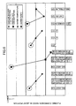
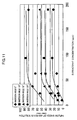
- FIG. 4 shows experiment results that leads to the pH range of 5.5 to 10.0 described above.
- the experiment results show the effect of pH in the aqueous solution 20 in the immersing step with respect to dissolution or corrosion of the joint portion 2a of the vehicle body 2.
- a test piece 37 was produced by welding two galvanized steel sheets 38 in a state of being spaced apart at a distance of 200 ⁇ m.
- Each of the pH-adjusted aqueous solutions 20 was put into the joint portion 2a of the two galvanized steel sheets 38, and the test piece 37 was baked at a temperature of 160°C for 30 minites (a solid substance appears in the joint portion 2a).
- the aqueous solution 20 in the immersing step contains the buffer solution component, and this buffer solution component remains as solid substance in the joint portion 2a due to evaporation of the water during the electrodeposition coating step. Accordingly, when water comes into the joint portion 2a later as in the above case, the water dissolves the buffer solution component (solid substance), and functions as a buffer solution. This solution prevents pH change in the joint portion 2a when the zinc plating starts to corrode, thereby preventing the corrosion from advancing.
- plots P1 and P3 are data points of the above experiment for the test pieces 37 using acetate and borate, respectively, as the buffer solution component in the aqueous solution 20. These results (P1, P3) show more excellent corrosion resistance than in the case of purified water (P2).
- the aqueous solution 20 in the immersing step contains, in addition to the buffer solution component, a chelating agent and/or a phosphate pigment as anode reaction inhibitors, and these anode reaction inhibitors remain as solid substance in the joint portion 2a due to the evaporation of the water during the electrodeposition coating step. Accordingly, when water comes into the joint portion 2a later, these anode reaction inhibitors (solid substance) dissolve in the water, capture zinc ion dissolving from the zinc plating of the vehicle body 2, and form a coating film. This coating film prevents the zinc plating from being ionized. Accordingly, the anode reaction inhibitors can prevent the joint portion 2a from being corroded.
- a chelating agent and/or a phosphate pigment as anode reaction inhibitors
- the aqueous solution 20 used in the immersing step contains Pb, Ce, Bi and the like as the halogen capturing chemical elements, and these halogen capturing chemical elements remain as solid substance in the joint portion 2a due to the evaporation of the water during the electrodeposition coating step. Accordingly, when water comes into the joint portion 2a later, these halogen capturing chemical elements are ionized by the water, capture chlorine (halogen) contained in the water which has entered into the joint portion 2a, and form a coating film. The coating film protects the joint portion 2a from chlorine.
- the quality of the aqueous solution 20 in the immersing step is controlled so as to have a pH of 5.5 to 10.0, and a degreasing agent concentration which is equal to or smaller than 1/100 of the degreasing agent concentration of the degreasing liquid 21 used in the degreasing step. Accordingly, the aqueous solution 20 can be considered not having a very high pH and substantially not containing the degreasing liquid 21, and Accordingly industrial action can be taken while making an efficient use of water.
- the presence of the aqueous solution 20 substantially not containing the degreasing liquid 21 in the joint portion 2a during the degreasing step will prevent oil from being removed out of the joint portion 2a, and this oil can be utilized to prevent the zinc plating in the joint portion 2a from dissolving.
- the present invention intends to protect the zinc plating from dissolving by the oil which is left rather than being removed before the coating step.
- plots P4 to P6 are data points of the above experiment when using an aqueous solution 20 containing a degreasing liquid
- plots P4' and P5' are data points of the above experiment when using an aqueous solution 20 containing a degreasing liquid which does not have surfactant.
- plot P6 is a data point when using an aqueous solution 20 containing the degreasing liquid in the degreasing step
- plot P5 is a data point when using an aqueous solution 20 obtained by 1/10-dilution of the degreasing liquid at plot P6
- plot P4 is a data point when using an aqueous solution 20 obtained by 1/100-dilution of the degreasing liquid at plot P6.
- Plot P5' is a data point when using an aqueous solution 20 by 1/10-dilution of the degreasing liquid at plot P6 but without surfactants
- plot P4' is a data point when using an aqueous solution 20 obtained by 1/100-dilution of the degreasing liquid at plot P6 but without surfactants.
- FIG. 4 the comparison of plots P4 to P6 (the aqueous solutions 20 containing the degreasing liquid with the surfactant) with plots P4' and P5' (the aqueous solutions 20 containing the degreasing liquid without the surfactant) shows that the plating dissolution rate is higher even at the same pH, and that the smaller amount of the degreasing liquid 21 provides a lower plating dissolution rate. This is because less degreasing liquid (especially degreasing liquid containing a surfactant) makes more oil to remain, and the plating in the joint portion 2a is prevented from dissolving based on the increased oil left.
- FIG. 6 showing properties of the aqueous solutions 20.
- FIG. 6 shows that less alkaline builder and surfactant as components of the degreasing liquid 21 lead to less plating corrosion, a result similar to the result from FIG. 4 .
- the purified water supplied by the immersing tank 4 is ion-exchanged water, and does not contain chlorine ion. Accordingly, the aqueous solution 20 coming into the joint portion 2a of the vehicle body 2 does not contain chlorine ion, thereby preventing corrosion due to chlorine ion in addition to corrosion (dissolution) due to the degreasing liquid 21.
- FIG. 6 shows a characteristic regarding water type (water purity) as one of the properties of the aqueous solution 20, wherein the plating corrosion ratio (S/N ratio) in the joint portion 21a is shown when ion-exchanged water, tap water, and industrial water are used as the aqueous solution 20 put into the joint portion 2a in the above experiment. This shows that the ion-exchanged water not containing chlorine ion provides a smaller corrosion ratio than the tap water and the industrial water.
- S/N ratio plating corrosion ratio
- FIG. 6 shows a characteristic regarding a water temperature as one of the properties of the aqueous solution 20, wherein the plating corrosion ratio (S/N ratio) in the joint portion 21a is shown at various temperatures of the aqueous solution 20 put into the joint portion 2a. This shows that a lower temperature results in a smaller corrosion ratio. This is thought to be because the oil in the joint portion 2a is more difficult to remove at a lower temperature of the aqueous solution 20.
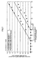
- FIG. 7 shows the result of a durability test of finished products (coating and the like has been performed thereon) produced with the immersing step (the case where the solid substance of the degreasing liquid does not remain in the sac-shaped portion) and without the immersing step (the case where the solid substance of the degreasing liquid remains in the sac-shaped portion).
- a GA material available from Nippon Steel Corporation; coating amount: 48.8 g/m 2 , degree of alloying: 10.4 Fe% was used as a test material, and the durability test was carried out under a constant conditions with one cycle approximately corresponding to three cycles of JISK5600-7-9 cycle A. In this case, 10 cycles corresponds to approximately one year in the marketed use. As shown in FIG.
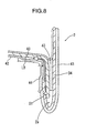
- coating-swelling rust (blister) 40 occurs at a coating 42 adjacent to a coating sealer 44 by development of rust from a starting point S1 in the sac-shaped portion as indicated by the arrow, and the width of the swelling of the coating 40 is indicated by LB.
- the numerals 41 and 43 designate a coating on the outer panel 34 and an AD sealer, respectively.
- the finished product which was produced without the immersing step and in which the solid substance of the degreasing liquid remained in the sac-shaped portion shows the durability equivalent to about two years in the marketed use, but the finished product which was produced through the immersing step and in which the solid substance of the degreasing liquid did not remain in the sac-shaped portion shows the durability equivalent to further two years in the marketed use.
- FIGS. 9 to 16 show a second embodiment of the present invention which is basically identical to the first embodiment except for some parts. Accordingly, only characteristic parts of the second embodiment will be described. For the other parts, the like elements to those of the first embodiment are designated by the same numerals, and the description thereof will be omitted.
- the second embodiment prevents corrosion of a joint portion 2a of a vehicle body 2 such as a hemmed portion as well as occurrence of abnormal aggregation or electrodeposition aggregation of an electrodeposition coating material liquid in the vicinity of the joint portion 2a during the electrodeposition coating step.
- a method for preventing electrodeposition aggregation is based on a mechanism of electrodeposition aggregation which has been discovered by the inventors. First, the discovered mechanism of electrodeposition aggregation will be described.
- a degreasing liquid 21 for a degreasing step (in a degreasing tank 5) contains an alkaline builder and a surfactant as described above, and metal salts such as sodium silicate (Na 2 SiO 3 ), sodium carbonate (Na 2 CO 3 ), and sodium hydrogen carbonate (NaHCO 3 ) are generally used as the alkaline builder.
- metal salts such as sodium silicate (Na 2 SiO 3 ), sodium carbonate (Na 2 CO 3 ), and sodium hydrogen carbonate (NaHCO 3 ) are generally used as the alkaline builder.
- Such metal salts enter treat water in first and second water washing tanks 6 and 7 during a water washing step after the degreasing step, and further enters an aqueous solution 20 in an immersing tank 4 because of reuse of the used water (see FIG. 2 ).
- the aqueous solution 20 containing the dissolved metal salts (ionized and non-ionized metal salts) comes into the joint portion 2a of the vehicle body 2 during the immersing step, and the vehicle body 2 having the joint portion 2a is advanced to the electrodeposition coating step after going through the degreasing step, the waterwashing step, and the chemical film forming step while holding the aqueous solution 20 in the joint portion 2a.
- the vehicle body 2 is immersed in a cationic electrodeposition coating material liquid in a tank, and an electric voltage is applied between the tank as an anode and the vehicle body 2 as a cathode.
- Electrodeposition coating material liquid chemical equilibration is maintained as shown by Formula 3. Accordingly, in the electrodeposition coating material liquid, a resin (electrodeposition coating material) becomes water soluble by lowering the pH (by acid being present therein), and generally this situation does not cause electrodeposition aggregation to occur. However, in the electrodeposition coating step, electrodeposition aggregation is actually observed in the vicinity of the joint portion 2a, and it is necessary to repair the joint portion 2a.
- the inventors studied this in view of such circumstances found that during the electrodeposition coating step, the temperature of the vehicle body 2 rises due to the application of the electric voltage, and the aqueous solution 20 thermally expands in the joint portion 2a such as the hemmed portion and overflows into the electrodeposition coating material liquid as shown in FIG. 9 . Based on this, the mechanism of electrodeposition aggregation, which is shown in FIG. 9 , was found. The mechanism will be described specifically with one metal salt, Na 2 SiO 3 , being taken as an example.
- R'-COOH is present around the electrodeposition coating material to provide water solubility to the resin.
- the aqueous solution 20 overflows and Na 2 SiO 3 , Na + , and SiO 3 2- enter the electrodeposition coating material liquid in such a situation, they enter an ionization equilibrium state in accordance with the condition of the electrodeposition coating material liquid as shown by Formula 4.
- Na + and the O atom (negatively-charged) in R'-COOH attract each other, while Na + and the H atom (positively-charged) in R'-COOH repel each other.
- the inventors found that more Na+ present in the electrodeposition coating material liquid increases the ionization degree of R'-COOH and a larger ionization degree of R'-COOH increases the amount of electrodeposition aggregation. Based on this finding, the inventors conclude that an upper limit is needed for the Na+ concentration in the electrodeposition coating material liquid in order to prevent the occurrence of electrodeposition aggregation.
- the inventors perceive that electrodeposition aggregation takes place owing to the fact that the abundance of R'-COO - shifts the equilibrium state of the electrodeposition coating material liquid toward the side in which the electrodeposition coating material condenses, as shown in Formula 11
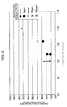
- FIG. 10 shows results of a test carried out by the inventors based on the above findings and conclusions (prediction that the pH and the concentration of metal salts and its ions in the aqueous solution 20 are linked to electrodeposition aggregation).
- a test liquid of each condition shown in FIG. 10 was poured into a petri dish, and a drop of a cationic electrodeposition coating material liquid (PN1020 available from Nippon Paint Co. , Ltd.) was put into each petri dish to check whether or not aggregation of the electrodeposition coating material liquid occurs under each condition. Evaluation of the test results was based on whether the phenomenon of electrodeposition aggregation was visually confirmed or not.
- the mark " ⁇ " means that the phenomenon of electrodeposition aggregation was not confirmed, and the mark " ⁇ " means that the phenomenon of electrodeposition aggregation was confirmed. In this case, as shown in FIG.
- a "converted metal ion concentration" (“converted Na + concentration”) is used as a total concentration of the metal salts (Na 2 SiO 3 , Na 2 CO 3 , NaHCO 3 ) and their ions (Na + ) which are held in equilibrium in the aqueous solution 20.
- the "converted metal ion concentration” is a total metal ion concentration (Na + concentration) when all the metal salts including the non-ionized metal salts are assumed to be fully ionized in the aqueous solution 20.
- the metal ion concentration in the electrodeposition coating material liquid is determined based on the chemical equilibrium state in the electrodeposition coating material liquid, and even if the metal ion concentration in the immersing step (immersing tank 4) is determined, the metal ion concentration in the immersing step is not necessarily the same as that in the electrodeposition coating material liquid in the electrodeposition coating step, thereby lacking accuracy.
- the total concentration of all the elements which can become metal ions the total concentration of metal ions among the immersing step and the electrodeposition coating step can be considered as constant, and this approximation is advantageous in identifying a condition to prevent the occurrence of electrodeposition aggregation.
- the final metal ion concentration after full ionization will differ even at the same metal salt concentration depending on the type of metal salt and the ratio among these.
- the converted Na + concentration of the aqueous solution 20 which can prevent the occurrence of electrodeposition aggregation must be set equal to or smaller than 620 ppm, as shown in the result in FIG. 10 .
- the quality of the aqueous solution 20 in the immersing step is controlled such that its pH is equal to or lower than pH 10 and its converted Na + concentration is equal to or smaller than 620 ppm.
- the dilution by the purified water supply source 9, the pH adjustment by an agent such as HNO 3 , and the like may be used as means for accomplishing this adjustment.
- the quality of the aqueous solution 20 in the immersing tank 4 is controlled so as to have a pH of 5.5 to 10.0, a converted Na + concentration equal to or smaller than 620 ppm, and a surfactant concentration of 50 ppm to 190 ppm (preferably from 50 ppm to 100 ppm).
- the permeating power of the surfactant of the aqueous solution 20 is utilized to cause the aqueous solution 20 to easily and rapidly enter into the joint portion 2a, thereby reducing the volume or the lateral length of the immersing tank 4.
- the preferable concentration of the surfactant ranges from 50 ppm to 100 ppm is to obtain the maximum permeating power effect (the effect of inflow into the joint portion 2a) with the minimum amount of surfactant contained while preventing the corrosion of the joint portion 2a.
- FIG. 11 shows the results of the test which provides the preferable conditions about the surfactant concentration of the aqueous solution in the immersing step (immersing tank 4) ranging from 50 ppm to 190 ppm, more preferably, ranging from 50 ppm to 100 ppm.
- This test aims at measuring the effect of the surfactant concentration on the inflow speed of the aqueous solution 20 into the hemmed portion (joint portion) 2a. Press washing oil was applied into colorless and transparent tubes each having a length of 300 mm and an inner diameter of 1 mm to prepare test tubes.
- test results shown in FIG. 11 show that the inflow speed increases in a range of the surfactant concentration from 0 ppm to just above 50 ppm (60ppm), while the inflow speed does not increase in a range of the surfactant concentration from 100 ppm to 190 ppm.
- the identical results were obtained at the different immersion angles of the test tubes.
- FIGS. 12 and 13 show results of an experiment which was carried out to measure the effect of surfactant with respect to corrosion. The experiment was carried out based on the experiment method shown in FIG. 4 in the first embodiment.
- FIGS. 12 and 13 show that corrosion preventing performance deteriorates with an aqueous solution 20 containing surfactant.
- the pH of the aqueous solution 20 is appropriately adjusted at pH 10 or lower (adjustment by HNO 3 and the like) and the surfactant concentration is equal to or smaller than 190 ppm, the corrosion preventing performance reduces to some extent (to the extent which slightly exceeds the allowable reference line in FIG.
- the surfactant concentration is set in the range of 50 ppm to 190 ppm as described above.
- the surfactant contained in the recovered liquid (the surfactant which has been used in the degreasing step) is reused in the immersing step.
- a nonionic surfactant such as alkyl ethoxylate
- the degreasing liquid in the degreasing tank 5 has the converted Na + concentration of 6200 ppm and the surfactant concentration of 1900 ppm.
- the degreasing liquid is diluted to 1/10 or smaller (preferably 1/40, more preferably 1/100) of the degreasing agent concentration of the degreasing liquid in the degreasing tank 5, and then reused in the immersing tank 4.
- the pH of the reused degreasing liquid is adjusted to be equal to or lower than 10 by HNO 3 or the like.
Landscapes
- Chemical & Material Sciences (AREA)
- Chemical Kinetics & Catalysis (AREA)
- General Chemical & Material Sciences (AREA)
- Engineering & Computer Science (AREA)
- Materials Engineering (AREA)
- Metallurgy (AREA)
- Organic Chemistry (AREA)
- Mechanical Engineering (AREA)
- Electrochemistry (AREA)
- Cleaning And De-Greasing Of Metallic Materials By Chemical Methods (AREA)
- Detergent Compositions (AREA)
Claims (14)
- Entfettungsverfahren, umfassend die Schritte:Zulassen, dass ein Verbindungsabschnitt (2a) eines Gegenstands (2) behandelt wird, eine wässrige Lösung (20) mit einem pH von 5,5 bis 10,0 aufzuweisen, undEintauchen des Gegenstands (2) in eine entfettende Flüssigkeit (21),wobei der Verbindungsabschnitt (2a) des Gegenstands (2) in einen Sack geformt ist, die entfettende Flüssigkeit (21) nicht die wässrige Lösung (20), welche in den sackförmigen Abschnitt eingetreten ist, ersetzen kann und die wässrige Lösung (20) in dem sackförmigen Abschnitt verbleibt.
- Entfettungsverfahren gemäß Anspruch 1, wobei das Eintauchen durchgeführt wird, bevor eine Elektroabscheidungsbeschichtung durchgeführt wird, und die wässrige Lösung (20) ein Metallsalz und Metallionen des Metallsalzes in einer Konzentration von 620 ppm oder geringer enthält, wenn das Metallsalz angenommen wird, zu Metallionen umgewandelt zu werden.
- Entfettungsverfahren gemäß Anspruch 1 oder 2, wobei die wässrige Lösung (20) im Wesentlichen kein grenzflächenaktives Mittel enthält.
- Entfettungsverfahren gemäß Anspruch 1 oder 2, wobei die Entfettungsflüssigkeit (21) ein grenzflächenaktives Mittel bei einer ersten Konzentration von grenzflächenaktivem Mittel enthält, und
die wässrige Lösung (20) ein grenzflächenaktives Mittel bei einer zweiten Konzentration von grenzflächenaktivem Mittel enthält, die gleich oder geringer als 1/100 der ersten Konzentration von grenzflächenaktivem Mittel ist. - Entfettungsverfahren gemäß einem der Ansprüche 1 bis 4, wobei der Gegenstand (2) eine Vielzahl von Platten einschließt, welche miteinander verbunden sind, und der Verbindungsabschnitt (2a) an einem überlappenden Teil der Platten ist.
- Entfettungsverfahren gemäß Anspruch 5, wobei die wässrige Lösung (20) in den Verbindungsabschnitt (2a) eingeführt wird, nachdem die Vielzahl von Platten verbunden worden sind, um den Gegenstand (2) aufzubauen.
- Entfettungsverfahren gemäß einem der Ansprüche 1 bis 7, wobei der Verbindungsabschnitt (2a) in die wässrige Lösung (20), enthalten in einem Eintauchbehälter (4), eingetaucht wird, um die wässrige Lösung (20) in den Verbindungsabschnitt (2a) einzuführen.
- Entfettungsverfahren gemäß Anspruch 2, wobei die wässrige Lösung (20) ein grenzflächenaktives Mittel bei einer Konzentration von 50 ppm bis 190 ppm enthält.
- Entfettungsverfahren gemäß Anspruch 8, wobei der Verbindungsabschnitt (2a) in die wässrige Lösung (20), enthalten in einem Eintauchbehälter (4), eingetaucht wird, um die wässrige Lösung (20) in den Verbindungsabschnitt (2a) einzuführen,
die Entfettungsflüssigkeit (21) ein Entfettungsmittel, einschließend ein Metallsatz und ein grenzflächenaktives Mittel, enthält und
die wässrige Lösung (20) in dem Eintauchbehälter (4) einen Teil an verwendeter Entfettungsflüssigkeit enthält und eine Entfettungsmittelkonzentration aufweist, die gleich oder geringer als 1/10 einer Entfettungsmittelkonzentration der Entfettungsflüssigkeit (21) ist. - Entfettungsverfahren gemäß einem der Ansprüche 1 bis 9, wobei die wässrige Lösung (20) ionenausgetauschtes Wasser einschließt.
- Entfettungsverfahren gemäß einem der Ansprüche 1 bis 10, wobei die wässrige Lösung (20) eine Pufferlösung einschließt.
- Entfettungsverfahren gemäß einem der Ansprüche 1 bis 11, wobei die wässrige Lösung (20) einen Anodenreaktionsinhibitor enthält.
- Entfettungsverfahren gemäß einem der Ansprüche 1 bis 12, wobei die wässrige Lösung (20) ein Halogenfänger-chemisches Element enthält.
- Entfettungsverfahren gemäß einem der Ansprüche 1 bis 13, wobei eine Oberfläche des Gegenstands (2) aus einem amphoteren Metall ist.
Applications Claiming Priority (2)
| Application Number | Priority Date | Filing Date | Title |
|---|---|---|---|
| JP2007286181 | 2007-11-02 | ||
| JP2008229996A JP2009132993A (ja) | 2007-11-02 | 2008-09-08 | 脱脂前処理方法及びその装置 |
Publications (3)
| Publication Number | Publication Date |
|---|---|
| EP2055805A2 EP2055805A2 (de) | 2009-05-06 |
| EP2055805A3 EP2055805A3 (de) | 2011-06-29 |
| EP2055805B1 true EP2055805B1 (de) | 2014-04-02 |
Family
ID=40282314
Family Applications (1)
| Application Number | Title | Priority Date | Filing Date |
|---|---|---|---|
| EP20080018915 Ceased EP2055805B1 (de) | 2007-11-02 | 2008-10-29 | Verfahren und Vorrichtung zur Entfettung |
Country Status (1)
| Country | Link |
|---|---|
| EP (1) | EP2055805B1 (de) |
Families Citing this family (2)
| Publication number | Priority date | Publication date | Assignee | Title |
|---|---|---|---|---|
| ITVR20120134A1 (it) * | 2012-07-03 | 2014-01-04 | Gianfranco Natali | Metodo per la preparazione alla verniciatura di telai metallici di cassoni di veicoli e di telai metallici di veicoli, costituiti da una pluralità di parti connesse reciprocamente |
| ITVR20120135A1 (it) * | 2012-07-03 | 2014-01-04 | Gianfranco Natali | Metodo per la preparazione alla verniciatura di telai metallici di cassoni di veicoli e di telai metallici di veicoli, costituiti da una pluralità di parti connesse reciprocamente |
Family Cites Families (11)
| Publication number | Priority date | Publication date | Assignee | Title |
|---|---|---|---|---|
| GB1450836A (en) * | 1974-03-25 | 1976-09-29 | Carrier Drysys Ltd | Treating automobile bodies |
| US4205101A (en) * | 1974-08-19 | 1980-05-27 | Imperial Chemical Industries Limited | Pretreatment process |
| US4974307A (en) * | 1988-06-20 | 1990-12-04 | Mazda Motor Corporation | Method of making an automobile body |
| EP0845025A4 (de) * | 1995-07-25 | 2000-02-23 | Henkel Corp | Zusammensetzung und verfahren zum entfetten von metalloberflächen |
| DE69708836D1 (de) * | 1997-03-12 | 2002-01-17 | Showa Denko Kk | Wasch- und Reinigungsmittel |
| JP3658257B2 (ja) * | 1998-12-24 | 2005-06-08 | キヤノン株式会社 | 洗浄方法及び洗浄装置及び電子写真感光体及び電子写真感光体の製造方法 |
| USH2089H1 (en) * | 1999-08-03 | 2003-11-04 | Henkel Corporation | Compositions useful for degreasing metal surfaces |
| JP2001152375A (ja) * | 1999-11-05 | 2001-06-05 | Nippon Parkerizing Co Ltd | 硬質表面のクリーニング方法並びにそれに使用する組成物 |
| US6308719B1 (en) * | 2000-03-29 | 2001-10-30 | Honda Of America Manufacturing, Inc. | Pre-clean deluge system |
| US6694804B1 (en) * | 2002-09-23 | 2004-02-24 | Ppg Industries Ohio, Inc. | Method and device for evaluating and/or adjusting the cleaning performance of a cleaning liquid |
| JP2004238681A (ja) | 2003-02-06 | 2004-08-26 | Honda Motor Co Ltd | 自動車用ボディの脱脂槽および化成槽の昇温システム並びにその昇温方法 |
-
2008
- 2008-10-29 EP EP20080018915 patent/EP2055805B1/de not_active Ceased
Also Published As
| Publication number | Publication date |
|---|---|
| EP2055805A2 (de) | 2009-05-06 |
| EP2055805A3 (de) | 2011-06-29 |
Similar Documents
| Publication | Publication Date | Title |
|---|---|---|
| CN102066612B (zh) | 用于金属表面的基于Ti/Zr的最佳钝化 | |
| JP7206353B2 (ja) | 金属基体用の洗浄組成物 | |
| JP6815494B2 (ja) | 溶融亜鉛メッキのための方法及びフラックス | |
| JP5722350B2 (ja) | 亜鉛表面のアルカリ不動態化のための組成物 | |
| JP5322000B2 (ja) | 亜鉛又は亜鉛合金めっきに耐食性皮膜を形成させるための表面処理水溶液及び処理方法 | |
| US20040187967A1 (en) | Chemical conversion coating agent and surface-treated metal | |
| KR20130109938A (ko) | 금속 표면에 방식층을 형성하는 방법 | |
| US20180127883A1 (en) | Two-step sealing of anodized aluminum coatings | |
| KR20140018942A (ko) | 아연 표면을 가지는 금속 부품의 다단계 부식 방지 처리 | |
| JP2004500479A (ja) | りん酸塩処理、ポストリンス及び陰極電着塗装の一連の方法 | |
| JP4975378B2 (ja) | 金属の表面処理液、表面処理方法、表面処理材料 | |
| WO2013061705A1 (ja) | 鋼材の表面処理方法、塗装方法および機械部材の製造方法 | |
| EP2055805B1 (de) | Verfahren und Vorrichtung zur Entfettung | |
| US7473308B2 (en) | Gel containing phosphate salts for passivation | |
| KR100968333B1 (ko) | 알루미늄 합금용 표면 처리제 및 알루미늄 합금의 표면처리 방법 | |
| TW500828B (en) | Process for phosphating, after-washing and cathodic electro-dipcoating | |
| KR19990087077A (ko) | 저농도의 니켈 및/또는 코발트를 이용한 아연-포스파타이징 방법 | |
| JP2009132993A (ja) | 脱脂前処理方法及びその装置 | |
| US20170016119A1 (en) | Two-stage pre-treatment of aluminum comprising pickling and passivation | |
| TWI500813B (zh) | 在金屬表面形成腐蝕保護層之方法 | |
| CN107532305B (zh) | 在转化处理之前的包含聚合物的预漂洗 | |
| KR102403600B1 (ko) | 산화막 제거와 피막 형성 동시 처리제 및 그가 적용된 연속 도장처리방법 | |
| KR102278974B1 (ko) | 다단계 전착 방법 | |
| CN111094624A (zh) | 包括酸洗和转化处理的铝(特别是铸造铝合金)的两级预处理 | |
| JPH07150393A (ja) | 金属表面処理方法 |
Legal Events
| Date | Code | Title | Description |
|---|---|---|---|
| PUAI | Public reference made under article 153(3) epc to a published international application that has entered the european phase |
Free format text: ORIGINAL CODE: 0009012 |
|
| AK | Designated contracting states |
Kind code of ref document: A2 Designated state(s): AT BE BG CH CY CZ DE DK EE ES FI FR GB GR HR HU IE IS IT LI LT LU LV MC MT NL NO PL PT RO SE SI SK TR |
|
| AX | Request for extension of the european patent |
Extension state: AL BA MK RS |
|
| PUAL | Search report despatched |
Free format text: ORIGINAL CODE: 0009013 |
|
| AK | Designated contracting states |
Kind code of ref document: A3 Designated state(s): AT BE BG CH CY CZ DE DK EE ES FI FR GB GR HR HU IE IS IT LI LT LU LV MC MT NL NO PL PT RO SE SI SK TR |
|
| AX | Request for extension of the european patent |
Extension state: AL BA MK RS |
|
| RIC1 | Information provided on ipc code assigned before grant |
Ipc: C23G 1/14 20060101AFI20090202BHEP Ipc: C23G 1/20 20060101ALI20110526BHEP Ipc: C23C 22/78 20060101ALI20110526BHEP Ipc: C23G 1/26 20060101ALI20110526BHEP Ipc: C23G 1/16 20060101ALI20110526BHEP Ipc: C11D 11/00 20060101ALI20110526BHEP |
|
| 17P | Request for examination filed |
Effective date: 20111222 |
|
| AKX | Designation fees paid |
Designated state(s): DE |
|
| 17Q | First examination report despatched |
Effective date: 20130626 |
|
| GRAP | Despatch of communication of intention to grant a patent |
Free format text: ORIGINAL CODE: EPIDOSNIGR1 |
|
| INTG | Intention to grant announced |
Effective date: 20131118 |
|
| GRAS | Grant fee paid |
Free format text: ORIGINAL CODE: EPIDOSNIGR3 |
|
| GRAA | (expected) grant |
Free format text: ORIGINAL CODE: 0009210 |
|
| AK | Designated contracting states |
Kind code of ref document: B1 Designated state(s): DE |
|
| REG | Reference to a national code |
Ref country code: DE Ref legal event code: R096 Ref document number: 602008031218 Country of ref document: DE Effective date: 20140515 |
|
| REG | Reference to a national code |
Ref country code: DE Ref legal event code: R097 Ref document number: 602008031218 Country of ref document: DE |
|
| PLBE | No opposition filed within time limit |
Free format text: ORIGINAL CODE: 0009261 |
|
| STAA | Information on the status of an ep patent application or granted ep patent |
Free format text: STATUS: NO OPPOSITION FILED WITHIN TIME LIMIT |
|
| 26N | No opposition filed |
Effective date: 20150106 |
|
| REG | Reference to a national code |
Ref country code: DE Ref legal event code: R097 Ref document number: 602008031218 Country of ref document: DE Effective date: 20150106 |
|
| REG | Reference to a national code |
Ref country code: DE Ref legal event code: R084 Ref document number: 602008031218 Country of ref document: DE |
|
| PGFP | Annual fee paid to national office [announced via postgrant information from national office to epo] |
Ref country code: DE Payment date: 20181016 Year of fee payment: 11 |
|
| REG | Reference to a national code |
Ref country code: DE Ref legal event code: R119 Ref document number: 602008031218 Country of ref document: DE |
|
| PG25 | Lapsed in a contracting state [announced via postgrant information from national office to epo] |
Ref country code: DE Free format text: LAPSE BECAUSE OF NON-PAYMENT OF DUE FEES Effective date: 20200501 |